1
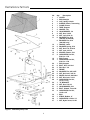
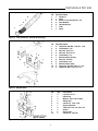
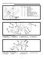
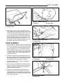
ATTACHMENT
OPERATOR’S
MANUAL
Turbo
Wide Body Cart & Hitch
Mfg. No.
1691526
1692526
Description
Turbo Wide Body Cart & Hitch
(for SunStar / 1900 / 2900 Series & Sovereign / 900 / 2800 Series)
Turbo Wide Body Cart & Hitch
(for Landlord / 1700 / 2700 Series & Broadmoor / 1600 / 2600 Series)
1714467-01
Rev 11/97
TP 100-2126-01-AT-SMA
MANUFACTURING, INC.
500 N Spring Street / PO Box 997
Port Washington, WI 53074-0997
www.simplicitymfg.com
© Copyright 1997 Simplicity Manufacturing, Inc.
All Rights Reserved. Printed in USA.
Table of Contents
TABLE OF CONTENTS
SPECIFICATIONS ........................................................1
DISCHARGE TUBE INSTALLATION.........................11
Landlord...........................................................................11
Broadmoor .......................................................................11
SunStar............................................................................11
Sovereign.........................................................................11
ILLUSTRATIONS & PART LISTS ................................2
Wide Body Dump Cart .......................................................2
Tube Assembly (SunStar & Sovereign) .............................3
SunStar Hitch.....................................................................3
Sovereign Hitch .................................................................3
Tube Assembly (Landlord & Broadmoor) ..........................4
Landlord Hitch....................................................................4
Broadmoor Hitch................................................................4
CONNECTING CART TO TRACTOR.........................12
MAINTENANCE ..........................................................12
Cleaning Clear Tube........................................................12
Cover ...............................................................................12
Wheels.............................................................................12
Tires.................................................................................12
SAFETY RULES ...........................................................5
CART ASSEMBLY........................................................6
OPERATION ...............................................................13
COVER ASSEMBLY.....................................................7
Before Operation .............................................................13
During Operation .............................................................13
Dumping Grass and Leaves ............................................13
Operating Without Collection System ..............................14
Reinstalling After Removal ..............................................14
HITCH ASSEMBLY.......................................................9
SunStar..............................................................................9
Sovereign...........................................................................9
Landlord.............................................................................9
Broadmoor .......................................................................10
Specifications
SPECIFICATIONS
WARNING
Overall Length ................................................................42”
Overall Width ..................................................................46”
Overall Height..............................................................41.4”
Inside Box Length...........................................................31”
Inside Box Width.............................................................44”
Inside Box Height .............................................................7”
Box Capacity............................................................5 cu. ft.
Weight Capacity ......................................................400 lbs.
Grass Capacity...................................................17 bushels
Pneumatic Tire Size..........................................410/350 x 4
The maximum weight capacity is 400 lbs. Do not
exceed the maximum capacity.
© Copyright 1997 Simplicity Manufacturing, Inc.
All Rights Reserved.
TP 100-2126-01-AT-SMA
1
Illustrations & Part Lists
No.
1
2
3
4
5
6
7
8
9
10
11
12
13
14
15
16
17
18
19
20
21
22
23
24
25
26
27
28
29
30
31
32
33
34
35
36
37
Figure 1. Wide Body Dump Cart
2
Qty.
Description
1 COVER
1 ROD, Straight
2 CLIP, Safety, Hairpin
1 SLEEVE, Plastic, Connecting
1 CLAMP, Sleeve
1 TUBE, Support
2 HANDLE, Lift
4 LOCKWASHER, 1/4
4 NUT, Hex, 1/4-20
4 NUT, Lock, 5/16-18
6 WASHER, Flat, 5/16
(1691367 & 1691358)
6 WASHER, Flat, 5/16
(1691526 only)
1 HANDLE, Latch
2 WASHER, Spring, 5/16
1 NUT, Hex, Full, 5/16-18
1 NUT, Jam, 5/16-18
2 SPACER, Plastic, 5/16
4 CAPSCREW, Hex Hd.,
5/16-18 x 1-1/2
1 ROD, Frame
1 CAPSCREW, Hex Hd.,
5/16-18 x 1-1/4
1 ROD, Support
8 BOLT, Hex, 3/8-16 x 1
2 PIN,1/2x 1-1/4
1 FRAME
8 WASHER, Flat, 3/8 S.A.E.
8 NUT, Hex Lock, 3/87-16
2 WHEEL, Swivel, 410/350-4
2 NUT, Hex Lock, 1/2-13
2 CAPSCREW, Hex Hd.,
1/2-13 x 1-1/4
1 "U" BRACKET
3 NUT, Hex, 5/16-18
3 LOCKWASHER, 5/16
3 BOLT, Slotted, Truss Hd.
4 CAPSCREW, Hex Hd.,
1/4-20 x 1/2
1 BOX
1 STRAP, Rubber, 6"
1 CAPSCREW, 1/4-20 x 1/2
1 NUT, Nylon insert, 1/4-20
Illustrations & Part Lists
7
6
5
4
3
2
1
No.
1
2
3
4
5
6
7
Qty.Description
1 Clamp, 6”
1 Hose
4 Screw, Truss Hd. #10-32 x 1/2
4 Plain Washer
4 Hex Nut #10-32
1 Tube
1 Decal
No.
1
2
3
4
5
6
7
8
9
10
11
Qty.Description
4 Capscrew, Hex Hd., 7/16-14 x 1-1/2
4 Lockwasher, 7/16
4 Nut, Hex, Full, 7/16
2 Nut, Hex, Full, 1/2-13
2 Lockwasher, 1/2
1 Bracket, Hitch (Frame)
2 Nut, Hex, Full, 5/8
2 Lockwasher, 5/8
2 Bracket, Hitch (Cart)
2 Capscrew, Hex Hd.,5/8-11 x 1-1/4
2 Capscrew, Hex, 1/2-13 x 1-1/4
Figure 2. Tube Assembly - Sunstar & Sovereign
1
2
10
9
3 2
3
1
4
5
8
7
6
11
Figure 3. Sunstar Hitch
No.
1
2
3
4
5
6
7
8
9
10
5
Figure 4. Sovereign Hitch
3
Qty.
2
1
3
1
2
1
2
1
2
1
Description
Locknut, 1/2-13
U-Bracket
Washer, Flat, 112x1 x9/64
Safety Clip
Clevis Pin, 7/16x 1-3/4
Support Bracket
Capscrew, Hex, 1/2-13x1-112
Spacer
Spring Clip
Clevis Pin, 112x718
Illustrations & Part Lists
No.
1
2
3
4
5
6
7
8
9
Qty.
1
1
1
1
2
2
6
12
6
Description
Clip, Spring
Lower Tube Assy.
Middle Tube
Upper Tube
Carriage Bolt, 1/4-20 x 5/8
Nut, Hex, Flange, Lock, 1/4-20
Screw, Truss Hd., 10-32 x 1/2
Washer, Flat, #10
Nut-Hex Washer Assembly, 10-32
Figure 5. Tube Assembly - Landlord & Broadmoor
C
G
D
F
D
C
B
E
F
A
Figure 6. Hitch Assembly - Landlord
A. Hitch Bracket
B. Hitch Support
E. Backside Drawbar
F. Flat washer, 1/2
H
C. Capscrew, 3/8-16 x 1
G. Capscrew, 1/2-13 x 1-1/4
D. Locknut, 3/8-16
H. Locknut, 1/2-13
E
E
G
B
F
C
D
Figure 7. Hitch Assembly - Broadmoor
A. Hitch Bracket
B. Hitch Adapter, Left
E. Locknut, 3/8-16
F. Drawbar
D
A
C. Hitch Adapter, Right
G. Drawbar Frame
4
D. Capscrew. 3/8-16 x 1
Safety Rules
WARNING
WARNING
Read these safety rules and the safety rules in
your tractor Operator’s Manual and follow them
closely. Failure to obey these rules could result
in loss of control of the vehicle, sever personal
injury to yourself, or damage to property or
equipment. The warning triangle in the test signifies important cautions or warnings which
must be followed.
When the blower assembly is removed from the
mower deck, the deflector must be installed as
described in Operating Without Collection
System.
SAFETY RULES
1. Know the tractor controls and how to stop quickly.
READ THE TRACTOR'S OWNER'S MANUAL.
9. CAUTION: Objects may be thrown from mower.
For your safety:
2. Shut the engine off before attaching, adjusting, or disconnecting the Collection System.
a. DO NOT remove the cover while the mower blades
are turning. Shut off the engine before opening cover
or removing the grass chute.
3. Check the cart to make sure it is attached tightly to
tractor.
4. Check the latch handle to make sure it is engaged so
the cart's box is locked to the frame.
b. Be sure the complete Collection System is in place
(cover secure and grass chute connected) before
operating the mower.
5. Look behind you to make sure the area is clear
before backing up.
c. Do check the cart cover frequently for wear and
tear. Replace with a new cover for safety protection.
6. DO NOT turn sharply when the tractor is alongside a
building or any object.
10. For best results when mowing grass set the mower to
cut from 1 to 2 inches of grass. If grass is exceptionally tall, set your mower as high a possible for first
cutting. Lower cutting height at succeeding cuttings
until proper height is reached. It may be necessary to
mow tall grass at a slower ground speed.
7. DO NOT carry passengers in the cart.
8. For added tractor stability and to prevent tipping or
loss of control:
a. Reduce ground speed on uneven ground and
when turning corners.
b. Reduce loads on hillsides. It is recommended that
the Collection System be kept only half full when
negotiating any slopes. Start mowing on slopes when
the Collection System is empty.
c. Mow up and down the face of slopes; never mow
across the face of any slope.
5
Cart Assembly
Figure 8. Wheel Assembly
A. Wheel Assembly
B. Frame
Figure 9. Install U-Bracket
A. U-Bracket
B. Box
CART ASSEMBLY
1. Install the wheel assemblies (A, Figure 8) to the
frame (B). Place the head of the swivel wheel on the
end of the frame. Align the holes and place four 3/816 x 1 hex bolts up through the frame and head of
the swivel. Secure with four flat washers (13/32 I.D.,
7/8 O.D.) and 3/8-16 locknuts.
2. Install the U-bracket (A, Figure 9) to the bottom of the
box (B). Place the three 5/16-20 x 3/4 slotted truss
head bolts and three flat washers (11/32 I.D., 3/4
O.D.) through the inside of the box and the U-bracket. Secure with three 5/16 lockwashers and nuts.
3. Turn box upside down and install the frame to the U
bracket (Figure 10). Align the two prong end (A) in
the frame with the ends of the U-bracket and secure
with two 1/2-13 x 1-1/4 hex bolts and locknuts. DO
NOT over-tighten the locknuts, since the box pivots at
this point for dumping.
Figure 10. Install Frame
A. Prong End
Note: The latch handle (A, Figure 11) is located on the
right hand side on cart, Mfg. No. 1691526 and on the left
hand side on cart, Mfg. No. 1692526.
4. Turn box with frame upright and install the latch handle (A, Figure 11) and two lift handles (B) as follows:
a. Latch Handle: Place one 5/16-18 x 1 hex bolt with
5/16 spring washer through the inside of the box.
Next place a 5/16 flat washer over the bolt on the outside of the box, the latch handle, a 5/16 flat washer, a
5/16 spring washer and a 5/16 nut and jam nut.
Tighten the nuts so that when the latch handle turns
the bolt and nut will not turn. (Be sure the cups of the
spring washers are facing toward the box surface on
both sides.)
Figure 11. Install Latch Handle
A. Latch Handle
B. Lift Handle
b. Lift Handles: Install the two lift handles on the outside of the box. Place two 1/4-20 x 1/2 slotted truss
head bolts through the inside of the box and the lift
handle. Secure with two 1/4 lockwashers and nuts.
6
Cover Assembly
Figure 13. Install Frame Rod
A. Opening
B. Frame Rod
Figure 12. Install Support Tube
A. Support Tube
5. Install support tube (A, Figure 12) inside the box.
Align each end of the support tube with the two holes
at the front corner side of the box. Place one 5/16-18
x 1-1/2 hex bolt with a 5/16 flat washer and plastic
spacer through the top, outside hole of the box and
the support tube. Secure with a 5/16 locknut on the
inside. At the bottom hole place on 5/16-18 x 1 -1/2
hex bolt with a 5/16 flat washer through the box and
the support tube. Secure with a 5/16 locknut.
Figure 14. Install Support Rod
A. Support Rod
COVER ASSEMBLY
1. Refer to Figure 13. Unfold the cover and spread it out
on a flat, clean surface with the white dust shield side
up. The two 3/8 inch rods are threaded through two
sleeves inside the cover. The rod with the two bent
ends is called the frame rod (B), since it lays on top
of the box's frame. The rod with the two eyebolt ends
is called the support rod, since it supports the top,
rear side of the cover.
2. Thread the frame rod through the bottom sleeve of
the cover so that the two bent ends protrude through
the openings on each side. The openings (A) of the
sleeve are found next to the black cord loops.
Figure 15. Connect Frame Rod and Support Rod
A. Frame Rod
B. Support Rod
3. Thread the support rod (A, Figure 14) through the
sleeve inside the cover.
4. Pick up the cover by holding the rods and place the
support rod inside the frame rod before hooking the
frame rod (A, Figure 19) through the eyelet of the
support rod (B) on each end.
5. Place the cover assembly over the support tube.
Insert the frame rod with the support rod attached
through the hole in the support tube and secure with
a flat washer (13/32 I.D., 7/8 O.D.) and safety clip (A,
Figure 16) on each side.
Figure 16. Secure Rods
A. Safety Clip
7
Cover Assembly
Figure 17. Install Connecting Sleeve
A. Connecting Sleeve
B. Support Tube
C. Sleeve Clamp
D. Truss Head Screw, 1/4-20 x 1/2
E. Nyloc Nut
Figure 18. Install Straight Rod
A. Straight Rod
6. Install the sleeve clamp (C, Figure 17) to the connecting sleeve (A) with 1/4-20 x 1/2 slotted truss head
screw (D) and nyloc nut (E). Install the connecting
sleeve inside the collar of the cover and position
sleeve clamp (C) over the support tube (B).
7. Thread the straight rod (A, Figure 18), which has an
eyelet on each end, through the sleeve at the front of
the cover.
Figure 19. Secure Cover
A. Straight Rod
B. Cord Loop
8. Pinch the black cord loop (B, Figure 19) and thread it
through the eyelet on each end of the rod. Next, pull
the loop over the top bolt (C) on each side of the box.
The rod gives added support to the cover at the front
of the box.
C. Bolt
9. Inside the cover at the front, there is a long tab with
an eyelet on the end. Pull this tab over the top of the
support tube (A, Figure 20) and back under the support tube before threading it through the slot in the
cover. This locking tab (B) secures the cover to the
support tube when the cover assembly is locked into
the open position for dumping.
Figure 20. Secure Cover To Support Tube
A. Support Tubes
B. Locking Tab
10. Install the six inch rubber strap (B. Figure 21) at the
back of the box. Hook the strap over the metal loop
(A) on the frame rod, which protrudes through the
cover. Close the hook with a pair of pliers. Hook the
other end of the strap over the door lock (C) on the
box.
Figure 21. Install Rubber Strap
A. Metal Loop
C. Door Lock
B. Rubber Strap
8
Hitch Installation
HITCH INSTALLATION
SunStar/1900 Series (Mfg. No. 1691526)
1. Install the U-bracket (A, Figure 22) with two 1/2-13 x
1 1/4 capscrews (B), 1/2 lockwashers, and nuts. At
top hole on each side, install two 7/16-14 x 1-1/2 cap
screws (C), lockwashers and nuts.
Note: The U-bracket (A, Figure 22) is an accessory hitch
with additional ear for tiller attachment. U-bracket (19,
Figure 1) supplied with cart mounts in same location with
supplied hardware.
2. See Figure 22. Position brackets (D) with large hole
(E) at bottom of each side. In large holes (E), install
5/8-11 x 1-1/4 capscrews, lockwashers and nuts.
Figure 22. Sunstar Hitch Installation
A. U-Bracket
D. Bracket
B. Capscrew, 1/2-13 x 1-1/4 E. Large Hole
C. Capscrew, 7/16-14 x 1/2 F. Capscrew, 7/16-14 x 1/2
3. In top holes of bracket (D), install two 7/16-14 x 1/2
capscrews (F), 7/16 lockwashers and nuts.
Sovereign/900 Series (Mfg. No. 1691526)
Note: Hitch assembly is packaged with the Turbo Blower
Assembly, Mfg. No. 1692257.
1. Assemble the hitch U-bracket (B, Figure 23) to the
support bracket (F) with two 1/2-13 x 1-1/2 capscrews (G) and locknuts (A).
2. Install hitch bracket assembly to tractor drawbar and
secure on sides with 1-3/4 clevis pins (D) and spring
clips (1).
Figure 23. Sovereign Hitch Installation
A. Locknut, 1/2-13
F. Support Bracket
B. U-Bracket
G.Capscrew, Hex, 1/2-13x1-1/2
C. Washer, Flat
H.Spacer
D. Safety Clip
I. Spring Clip
E. Clevis Pin, 7/16x1-3/4 J. Clevis Pin, 1/2 x 7/8
Landlord/1700 Series (Mfg. No. 1692526)
C
F
1. Assemble the hitch bracket (A, Figure 24) to the hitch
support (B) with two 3/8-16 x 1 capscrews (C) and
locknuts (D).
G
2. Position the hitch bracket to the top side of the drawbar (D) with the hitch support to the backside (F) of
the drawbar. Secure the hitch bracket with two 1/2-13
x 1 1/4 capscrews (G), flat washers (H), and locknuts
(I) and the hitch support with two 3/8-16 x 1 capscrews and locknuts.
C
D
D
E
A
B
H
G
Figure 24. Landlord Hitch Installation
A. Hitch Bracket
E. Backside Drawbar
B. Hitch Support
F. Capscrew, 1/2-13 x 1-1/4
C. Capscrew, 3/8-16 x 1
G. Flat washer, 1/2
D. Locknut, 3/8-16
H. Locknut, 1/2-13
9
Hitch Installation
Broadmoor/1600 Series (Mfg. No. 1692526)
E
E
1. Assemble the hitch bracket (A, Figure 25) to the hitch
adapters left (B) and right (C) with four 3/8-16 x 1 cap
screws (D) and locknuts (E).
G
B
2. Position the hitch bracket over the drawbar (F) with
the two hitch adapters on the outside of the drawbar
frame (F). Secure with four 3/8-16 x 1 capscrews and
lock nuts.
F
C
D
D
A
Figure 25. Hitch Assembly - Broadmoor
A. Hitch Bracket
E. Locknut, 3/8-16
B. Hitch Adapter, Left
F. Drawbar
C. Hitch Adapter, Right
G. Drawbar Frame
D. Capscrew. 3/8-16 x 1
Figure 26. Discharge Tube Installation
A.
B.
C.
D.
E.
Upper Tube
Middle Tube
Lower Tube
Spring Clip
Truss Head Screw, 10/32 x 1/2
F.
G.
H.
I.
10
Washer
Locknut, 10/32
Carriage Bolt, 1/4-20, 5/8
Flange Locknut, 1/4-20
Discharge Tube Installation
DISCHARGE TUBE INSTALLATION
Landlord/1700 Series (Mfg. No. 1692526)
Broadmoor/1600 Series (Mfg. No. 1692526)
1. Install the spring clip (D, Figure 26) with two 10/32 x
1/2 truss head screws (E), four flat washers (F), and
two locknuts (G).
2. Install 1/4-20 x 5/8 carriage bolt (H) through hole in
turbo housing. Secure with 1/4-20 flange locknut (I).
3. Position the lower tube (C) onto turbo housing and
hook inside spring clip onto flange locknut (I, installed
in step 2). Mark hole location on opposite side of
turbo housing for outer spring clip.
4. Remove lower tube and drill 9/32 hole in turbo housing and install 1/4-20 x 5/8 carriage bolt (H) through
hole. Secure with 1/4-20 flange locknut (I)
5. Assemble the upper tube (A) on to middle tube (B) as
shown in Figure 2 with two 10/32 x 1/2 truss head
screws (E), four flat washer (F), and two locknuts (G).
6. Install two 10/32 x 1/2 truss head screws (E), four flat
washer (F), and two locknuts (G) to the top holes in
the lower tube (C). Leave hardware loose.
7. Install upper tubes (A and B) to lower tube (C) and
tighten hardware.
8. Install tube assembly into cart sleeve and onto turbo
housing. Hook spring clips (D) onto flange locknuts (I)
installed on turbo housing.
SunStar/1900 Series (Mfg. No. 1691526)
Sovereign/900 Series (Mfg. No. 16911526)
A
1. Assemble the tube (A, Figure 27) to hose (B) with
four 10/32 x 1/2 truss head Phillips screws (C)
installed from inside hose. Secure on outside of tube
with #10 flat washers (D) and 10/32 locknuts (E).
B
C
D
2. Install hose (B) onto turbo housing and secure with
hose clamp (F).
E
F
G
3. Install the tube assembly into the connecting sleeve
of the cart.
Figure 27. Discharge Tube Installation
A. Decal
E. Truss Head Screw
B. Discharge Tube
F. Hose
C. Locknut, Hose
G. Clamp
D. Washer
11
Connecting Cart / Maintenance
CONNECTING CART TO TRACTOR
Place the cart frame (A, Figure 28) onto tractor brackets
and install the clevis pins (B) and springs clips (C).
Figure 28. Connecting Cart To Tractor
A. Cart Frame
C. Spring Clip
B. Clevis Pin
MAINTENANCE
WARNING
The cover is subject to wear and deterioration.
Check the cover frequently. Use an approved
replacement cover.
Cleaning Clear Tube
To clean the clear mid-tube on the SunStar and
Sovereign series collection systems, wash with warm
water and mild soap or detergent. Use a soft, clean
sponge or cloth. DO NOT use abrasive, alkaline, or
petroleum based cleaners.
Cover
WARNING
The cover can be rinsed with a hose when dirty. A dirty
cover will inhibit the fast flow of grass clippings into the
cover. Do not leave grass or leaves in the cart for a long
period of time.
Before opening the cover for any reason, engage
the parking brake, shut off the engine, remove
the key, and wait for all moving parts to stop.
Wheels
Lubricate the wheel assembly before using the cart and
as necessary thereafter. A grease fitting is located at
swivel base. Use SAE multi-purpose type grease.
Tires
The tire pressure should be 30 psi.
12
Operation
OPERATION
Before Operation
Clear the lawn of all sticks, stones, wire and other debris
which may be caught or thrown by the mower blades.
Clean the tube with mild detergent (other products may
damage tube). The flow of grass can be seen through
the tube while mowing.
CAUTION
Check grass condition. If wet, wait until later in the day. If
grass is wet, plugging may occur.
The maximum weight capacity of the cart is 400
lbs. Do not exceed.
For efficient bagging, air circulation under the mower
deck, through the chute and into the bag is very important. For this reason, you should remove grass and
debris from underside of mower deck, discharge chute
and cover.
The blower, tube and elbow can be removed for cleaning.
During Operation
Grass should be cut often, and not too short. If grass is
too long or lush it may be necessary to keep ground
speed to a minimum or to cut only half the width to prevent clogging. If grass is high, operate with mower in
high cutting position. Cut the grass again in lower cutting
position, if desired.
The collector is full when grass builds at the window.
Always operate with throttle at full speed.
Dumping Grass and Leaves
Figure 29. Opening the Cover
1. Back the tractor to the desired place for unloading.
Shut the tractor's engine of before getting off the tractor's seat.
2. Unhook the strap from the door lock and raise the
cover assembly to the open position. Lock the cover
in place by hooking the strap to the locking tab in
place by hooking the to the locking tab (Figure 29).
Also see Figure 30.
3. Move the latch handle to the unlock position and
dump the cart's box using one of the front lift handles.
The connecting sleeve will slide off the discharge
chute and the cart's box will dump at a 90° angle for
quick unloading.
4. If bagging the grass clippings is desired, the grass
can be pulled from the cart at the curve side into a
plastic lawn bag. Also, the grass can be dumped onto
a tarp for throwing into a trailer.
Figure 30. Emptying the Cart
13
Operation
Operating Without Collection System
WARNING
To operate without the collection system, the
blower assembly must be removed and the
deflector must be in down position.
1. Unhook the cart from the tractor by removing two clevis pins and spring clips (Figure 28).
2. To remove the blower, remove the belt from the pulley (A, Figure 31).
3. Close cover (D) and tighten knob.
4. Loosen wing nut (B) and, while holding deflector (C)
up, pull blower off mover.
Figure 31. Removing the Blower
A. Pulley
C. Deflector
B. Wing Nut
D. Cover
WARNING
The deflector is spring loaded. When removing
the blower, hold the deflector up. Then allow the
deflector to go down into normal operating position (see Figure 33).
5. Allow deflector to go down into position shown in
Figure 32.
NOTE: For easier belt removal, later model blowers have
a wire loop to move spring-loaded idler pulley.
Reinstallation After Removal
Raise the deflector to slide the blower into position.
Tighten the wing nut (B, Figure 31). Place the belt onto
the pulley (A) and close the cover (D) and tighten knob.
Connect cart and chute.
Figure 32. Deflector
14
Hardware Identification & Torque Specifications
Common Hardware Types
Torque Specification Chart
Hex Head Capscrew
FOR STANDARD MACHINE HARDWARE (Tolerance ± 20%)
Washer
Hardware
Grade
Lockwasher
Carriage Bolt
No
Marks
SAE Grade 2
Hex Nut
Size Of
Hardware
Standard Hardware Sizing
8-32
8-36
10-24
10-32
1/4-20
1/4-28
5/16-18
5/16-24
3/8-16
3/8-24
7/16-14
7/16-20
1/2-13
1/2-20
9/16-12
9/16-18
5/8-11
5/8-18
3/4-10
3/4-16
7/8-9
7/8-14
1-8
1-12
When a washer or nut is identified as 1/2”, this is the
Nominal size, meaning the inside diameter is 1/2 inch; if a
second number is present it represent the threads per inch
When bolt or capscrew is identified as 1/2 - 16 x 2”, this
means the Nominal size, or body diameter is 1/2 inch; the
second number represents the threads per inch (16 in this
example, and the final number is the body length of the
bolt or screw (in this example 2 inches long).
The guides and ruler furnished below are designed to
help you select the appropriate hardware and tools.
0
1/4
Nut, 1/2”
1/2
Inside
Diameter
3/4
1
1/4
1/2
3/4
Screw, 1/2 x 2
2
1/4
Body
Diameter
in/lbs
ft/lbs
19
20
27
31
66
76
11
12
20
23
30
35
50
55
65
75
90
100
160
180
140
155
220
240
Nm.
2.1
2.3
3.1
3.5
7.6
8.6
15.0
16.3
27.2
31.3
40.8
47.6
68.0
74.8
88.4
102.0
122.4
136
217.6
244.8
190.4
210.8
299.2
326.4
SAE Grade 5
in/lbs
ft/lbs
30
31
43
49
8
10
17
19
30
35
50
55
75
90
110
120
150
180
260
300
400
440
580
640
SAE Grade 8
Nm.
in/lbs
ft/lbs
Nm.
3.4
3.5
4.9
5.5
10.9
13.6
23.1
25.8
40.8
47.6
68.0
74.8
102.0
122.4
149.6
163.2
204.0
244.8
353.6
408.0
544.0
598.4
788.8
870.4
41
43
60
68
12
14
25
27
45
50
70
80
110
120
150
170
220
240
386
420
600
660
900
1,000
4.6
4.9
6.8
7.7
16.3
19.0
34.0
34.0
61.2
68.0
95.2
108.8
149.6
163.2
204.0
231.2
299.2
326.4
525.0
571.2
816.0
897.6
1,244.0
1,360.0
NOTES
1. These torque values are to be used for all hardware
excluding: locknuts, self-tapping screws, thread forming
screws, sheet metal screws and socket head setscrews.
2. Recommended seating torque values for locknuts:
a. for prevailing torque locknuts - use 65% of grade 5
torques.
b. for flange whizlock nuts and screws - use 135% of
grade 5 torques.
3. Unless otherwise noted on assembly drawings, all torque
values must meet this specification.
1/2
Body
Length
3/4
3
1/4
1/2
3/4
4
Wrench & Fastener Size Guide
1/4
5/16
3/8
1/4” Bolt or Nut
Wrench—7/16”
5/16” Bolt or Nut
Wrench—1/2”
3/8” Bolt or Nut
Wrench—9/16”
7/16
DIA.
7/16” Bolt or Nut
Wrench (Bolt)—5/8”
Wrench (Nut)—11/16”
1/2
DIA.
1/2” Bolt or Nut
Wrench—3/4”
Notes
16