1
Preface
SIMATIC Time synchronization (V7.1)
SIMATIC
Process Control System PCS 7
Time synchronization (V7.1)
Function Manual
03/2009
A5E01216578-01
1
______________
2
Fundamentals
______________
Configurations for time
synchronization of a PCS 7
plant
3
______________
Planning time
synchronization
4
______________
Configuring time
synchronization
5
______________
Checking time
synchronization
6
______________
Legal information
Legal information
Warning notice system
This manual contains notices you have to observe in order to ensure your personal safety, as well as to prevent
damage to property. The notices referring to your personal safety are highlighted in the manual by a safety alert
symbol, notices referring only to property damage have no safety alert symbol. These notices shown below are
graded according to the degree of danger.
DANGER
indicates that death or severe personal injury will result if proper precautions are not taken.
WARNING
indicates that death or severe personal injury may result if proper precautions are not taken.
CAUTION
with a safety alert symbol, indicates that minor personal injury can result if proper precautions are not taken.
CAUTION
without a safety alert symbol, indicates that property damage can result if proper precautions are not taken.
NOTICE
indicates that an unintended result or situation can occur if the corresponding information is not taken into
account.
If more than one degree of danger is present, the warning notice representing the highest degree of danger will
be used. A notice warning of injury to persons with a safety alert symbol may also include a warning relating to
property damage.
Qualified Personnel
The device/system may only be set up and used in conjunction with this documentation. Commissioning and
operation of a device/system may only be performed by qualified personnel. Within the context of the safety notes
in this documentation qualified persons are defined as persons who are authorized to commission, ground and
label devices, systems and circuits in accordance with established safety practices and standards.
Proper use of Siemens products
Note the following:
WARNING
Siemens products may only be used for the applications described in the catalog and in the relevant technical
documentation. If products and components from other manufacturers are used, these must be recommended
or approved by Siemens. Proper transport, storage, installation, assembly, commissioning, operation and
maintenance are required to ensure that the products operate safely and without any problems. The permissible
ambient conditions must be adhered to. The information in the relevant documentation must be observed.
Trademarks
All names identified by ® are registered trademarks of the Siemens AG. The remaining trademarks in this
publication may be trademarks whose use by third parties for their own purposes could violate the rights of the
owner.
Disclaimer of Liability
We have reviewed the contents of this publication to ensure consistency with the hardware and software
described. Since variance cannot be precluded entirely, we cannot guarantee full consistency. However, the
information in this publication is reviewed regularly and any necessary corrections are included in subsequent
editions.
Siemens AG
Industry Sector
Postfach 48 48
90026 NÜRNBERG
GERMANY
A5E01216578-01
Ⓟ 01/2009
Copyright © Siemens AG 2009.
Technical data subject to change
Table of contents
1
Preface ...................................................................................................................................................... 7
2
Fundamentals............................................................................................................................................ 9
3
2.1
Using time synchronization in PCS 7.............................................................................................9
2.2
Time synchronization options for PCS 7 components .................................................................11
2.3
Time displayed in PCS 7..............................................................................................................12
2.4
Time synchronization in distributed PCS 7 plants .......................................................................13
2.5
Central plant clock .......................................................................................................................16
2.6
Time levels for a PCS 7 plant (stratum).......................................................................................17
2.7
2.7.1
2.7.2
2.7.3
Time synchronization in PCS 7 - mode of operation ...................................................................20
Time master and time slave.........................................................................................................20
Time sources for a PCS 7 plant ...................................................................................................22
Example of the time synchronization sequence ..........................................................................23
2.8
2.8.1
2.8.2
2.8.3
2.8.4
2.8.5
2.8.6
Network environment of a PCS 7 plant........................................................................................25
Overview ......................................................................................................................................25
Legend for figures used in this documentation ............................................................................26
Network environment within a domain.........................................................................................27
Network environment within a work group...................................................................................28
Network environment in redundant, high-availability networks....................................................29
Network environment on separate networks with one central plant clock ...................................31
Configurations for time synchronization of a PCS 7 plant ........................................................................ 33
3.1
Overview of recommended configurations ..................................................................................33
3.2
Rules for time synchronization in PCS 7 .....................................................................................34
3.3
3.3.1
3.3.2
Configurations for time synchronization in a work group.............................................................36
Configuration of time synchronization with central time master in a work group.........................36
Configuration of time synchronization without central time master in a work group....................38
3.4
3.4.1
Configuration for time synchronization in a Windows domain .....................................................40
Configuration of time synchronization with central time master in a Windows domain with
a hierarchy ...................................................................................................................................40
Configuration of time synchronization with central time master in a Windows domain with
a hierarchy ...................................................................................................................................42
Configuration of the time synchronization in a Windows domain with multiple hierarchies.........44
3.4.2
3.4.3
4
Planning time synchronization ................................................................................................................. 45
4.1
Selecting the time master ............................................................................................................45
4.2
Selecting the central plant clock ..................................................................................................46
Time synchronization (V7.1)
Function Manual, 03/2009, A5E01216578-01
3
Table of contents
5
Configuring time synchronization ............................................................................................................. 49
5.1
Introduction ................................................................................................................................. 49
5.2
5.2.1
5.2.2
Setting the time displayed ........................................................................................................... 51
How to configure the operator station display............................................................................. 51
How to convert the local time zone and daylight saving time parameters.................................. 54
5.3
5.3.1
5.3.2
5.3.3
Overview of configuration steps, depending on the configuration .............................................. 56
Configuration steps for time synchronization with central time master in a work group ............. 56
Configuration steps for time synchronization without a central time master in a work group..... 57
Configuration steps for time synchronization with a central time master in a Windows
domain with a hierarchy .............................................................................................................. 58
Configuration steps for time synchronization without a central time master in a Windows
domain with a hierarchy .............................................................................................................. 59
5.3.4
5.4
5.4.1
5.4.2
5.4.3
5.4.4
Commissioning a central plant clock........................................................................................... 60
Commissioning the SICLOCK TC 400........................................................................................ 60
Commissioning the SICLOCK TM/TS......................................................................................... 64
Commissioning GPS receivers ................................................................................................... 66
Commissioning the DCF 77 receiver .......................................................................................... 69
5.5
5.5.1
5.5.2
5.5.3
5.5.4
5.5.5
5.5.6
Configuring the time synchronization of the OS ......................................................................... 71
Overview of configuration steps.................................................................................................. 71
How to set time synchronization on an OS in a work group with central time master ................ 72
How to set time synchronization on an OS in a work group without central master................... 75
How to set time synchronization on an OS in a domain with central time master ...................... 79
How to set time synchronization on an OS in a domain without central time master ................. 85
How to set the OS server for reception of time service via DCF77RS ....................................... 90
5.6
5.6.1
5.6.2
5.6.3
5.6.4
Configuring time synchronization for a PC station without OS ................................................... 92
Overview of configuration steps.................................................................................................. 92
How to make DCF 77 Client Service settings on a PC station without OS ................................ 93
How to set time synchronization on a BATCH/operator station.................................................. 95
How to set time synchronization on a route control/operator station.......................................... 95
5.7
5.7.1
Time synchronization via conventional point-to-point connections............................................. 96
Configuring directly connected time receivers ............................................................................ 96
5.8
5.8.1
5.8.2
Configuring time synchronization on an AS ................................................................................ 99
How to set time synchronization on an AS for SIMATIC mode .................................................. 99
How to set time synchronization on an AS for NTP mode........................................................ 105
5.9
5.9.2
5.9.3
5.9.4
5.9.5
Configuring time synchronization for the SIMATIC PCS 7 BOX and SIMATIC PCS 7 AS
RTX ........................................................................................................................................... 109
Overview of time synchronization for the SIMATIC PCS 7 BOX and SIMATIC PCS 7 AS
RTX ........................................................................................................................................... 109
How to set the time synchronization source ............................................................................. 111
How to set the OS properties .................................................................................................... 113
How to configure time synchronization of the AS ..................................................................... 114
How to set OS time synchronization ......................................................................................... 115
5.10
5.10.1
5.10.2
5.10.3
Configuring time synchronization with multiple networks ......................................................... 116
Configuring time synchronization for separate networks using a central clock ........................ 116
How to configure SCALANCE X414-3E for the separation of time signals .............................. 118
How to configure an OSM/ESM for separating time signals..................................................... 120
5.9.1
4
Time synchronization (V7.1)
Function Manual, 03/2009, A5E01216578-01
Table of contents
6
5.11
How to synchronize PC stations using NTP mode ....................................................................121
5.12
5.12.1
5.12.2
Configuring redundant PCS 7 systems......................................................................................122
How to configure time synchronization of OS servers with a redundant communication
module and external clock .........................................................................................................122
How to configure time synchronization on a PCS 7 system with redundant bus system ..........123
5.13
5.13.1
Configuring time synchronization of the domain controller (DC) ...............................................124
How to configure time synchronization of the domain controller ...............................................124
Checking time synchronization .............................................................................................................. 127
6.1
How to check the time of the PC stations ..................................................................................127
Glossary ................................................................................................................................................ 129
Index...................................................................................................................................................... 131
Time synchronization (V7.1)
Function Manual, 03/2009, A5E01216578-01
5
Table of contents
6
Time synchronization (V7.1)
Function Manual, 03/2009, A5E01216578-01
1
Preface
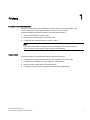
Purpose of this documentation
The time synchronization documentation provides support for the configuration and
commissioning of the "time synchronization" function in a PCS 7 plant.
The documentation provides information about the following topics:
● Time synchronization in a PCS 7 plant
● Planning time synchronization in a PCS 7 plant
● Configuring time synchronization for a PCS 7 plant
Note
You will find information on high-precision time stamping in the function manual
PCS 7 Process Control System; High-precision time stamping.
Organization
The documentation is organized according to the following topics:
● Fundamentals of time synchronization mode of operation in a PCS 7 plant
● Configuration possibilities of PCS 7 with time synchronization
● Planning a PCS 7 plant with time synchronization
● Configuring the time synchronization for different plant configurations
Time synchronization (V7.1)
Function Manual, 03/2009, A5E01216578-01
7
Preface
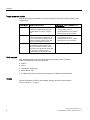
Target group and benefit
This documentation is intended for personnel working in the fields of sales, planning, and
configuration:
Target group
Using the documentation
Sales
Sales personnel give clear advice to their •
customers on implementing the "time
•
synchronization" function in a PCS 7
plant.
•
"Fundamentals"
"Configurations for time
synchronization of a PCS 7 plant"
"Planning time synchronization"
Planning
The system planner uses the information
in the documentation for optimal set up
and the components necessary in this
regard for planning a PCS 7 plant with
the "time synchronization function".
•
"Fundamentals"
"Configurations for time
synchronization of a PCS 7 plant"
"Planning time synchronization"
•
"Configuring time synchronization"
Configuration The configuration engineer is provided
with exact instructions relative to the
"time synchronization" function; these
instructions show the specific steps that
are necessary to adjust the time
synchronization at all relevant points.
Target-group relevant chapters of the
documentation
•
•
Skills required
Only qualified personnel should commission and operate the PCS 7 products.
Skills in the following areas are prerequisite:
● STEP 7
● PCS 7
● "Automation technology"
● Basic WinCC skills
● For plants with domain structure: Knowledge of the Windows administration
Validity
This documentation is valid for the software package Process Control System;
PCS 7 Toolset V7.1 or higher.
8
Time synchronization (V7.1)
Function Manual, 03/2009, A5E01216578-01
2
Fundamentals
2.1
Using time synchronization in PCS 7
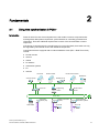
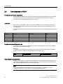
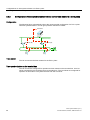
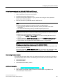
Introduction
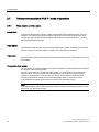
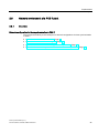
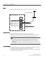
Plants in which Process Control Systems are used contain numerous components that
exchange data. Most plants require time synchronization for controlling processes and
information. There are additional requirements in terms of the documentation of event
sequences.
If the timing of components in the overall system is not synchronized, these tasks can only
be supported by the internal clock of the individual components.
Components that are equipped with an internal hardware clock (RTC = Real Time Clock)
include:
● Domain servers
● Servers
● Clients
● PC stations
● Automation systems
● I/O
● Sensors
26FOLHQWV
%$7&+FOLHQWV
5RXWH&RQWUROFOLHQWV
6,0$7,&,7
%$7&+VHUYHU
$UFKLYHVHUYHUV
7HUPLQDOEXV
26VHUYHU
(QJLQHHULQJ
VWDWLRQ
5RXWH&RQWURO
6HUYHU
3ODQWEXV
Time synchronization (V7.1)
Function Manual, 03/2009, A5E01216578-01
(70
+LJKDYDLODELOLW\
DXWRPDWLRQV\VWHPV
352),%86'3
)DLOVDIHDXWRPDWLRQ
V\VWHPV
352),%86'3
3&6%2;
352),%86'3
$XWRPDWLRQ
V\VWHPV$6
(70
9
Fundamentals
2.1 Using time synchronization in PCS 7
Time synchronization
Time synchronization means that one system component (time master) provides a precise
time for all the other components (time slaves). The time information (date and time) can
either be distributed by the time master, or be requested by the time slaves. For the overall
task, all components within the system must evaluate this time information.
Time synchronization applications
The list below contains various examples of aspects requiring time synchronization of all
components within the process automation:
● Synchronizing processes
● Controlling complex sequences
● Logging and documenting sequences
● Validating processes
● Analyzing processes
● Analyzing the causes and effects of events
PCS 7 functions
The following list contains some of the key PCS 7 functions for which time synchronization is
absolutely necessary:
● Interpretation of causal relationships
● Message processing in correct sequence
● Time stamp
● Time-of-day interrupts
● Runtime meter
● Redundancy compare
● Batch monitoring
● Authentication of a domain client
10
Time synchronization (V7.1)
Function Manual, 03/2009, A5E01216578-01
Fundamentals
2.2 Time synchronization options for PCS 7 components
2.2
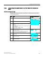
Time synchronization options for PCS 7 components
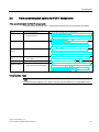
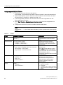
Time synchronization for PCS 7 components
The table below shows the PCS 7 components for which time synchronization is possible:
Station
Time synchronization
Operator station
•
•
Via the terminal bus
Via the plant bus
•
•
Via the operating system
•
BATCH station
For further information, refer to the section ...
•
•
Route Control
Station
•
Via the operating system
•
•
"How to set time synchronization on an OS in a domain with
central time master. (Page 79)"
"How to set time synchronization on an OS in a work group
with central time master (Page 72)"
"How to make DCF 77 Client Service settings on a PC
station without OS (Page 93)"
"How to set time synchronization on a BATCH/operator
station. (Page 95)"
"How to make DCF 77 Client Service settings on a PC
station without OS (Page 93)"
"How to set time synchronization on a route control/operator
station. (Page 95)"
SIMATIC PCS 7
BOX
•
At integration in a
PCS 7 plant
•
"Configuring time synchronization for the SIMATIC PCS 7
BOX and SIMATIC PCS 7 AS RTX (Page 109)"
AS
•
Via the plant bus
•
"How to set AS time synchronization (Page 99)"
Domain controller
•
With a domain controller as
•
time master on the terminal bus
•
"How to set time synchronization in a Windows domain with
a central time master (Page 40)"
"How to set time synchronization in a Windows domain
without a central time master (Page 42)"
V5-compatible mode
Note
Contact Customer Support if you want to use time synchronization in V5-compatible mode.
Time synchronization (V7.1)
Function Manual, 03/2009, A5E01216578-01
11
Fundamentals
2.3 Time displayed in PCS 7
2.3
Time displayed in PCS 7
Coordinated Universal Time (UTC)
Coordinated Universal Time (UTC) is an international time basis that takes as its precedent
the precision of atomic clocks. UTC refers to the Greenwich prime meridian in London.
UTC does not take daylight saving time into account.
Local time
East of the prime meridian, one or more hours is added to the universal time measured in
Greenwich, depending on the distance in question. West of the prime meridian, the hours
are subtracted.
The following table shows some examples of time zones and their time differences in relation
to UTC:
Location
Time zone
Zone time
Time
Greenwich
0. Longitude
UTC = Coordinated Universal Time
UTC 12:00
Berlin
15. Eastern longitude
CET = Central European Time
UTC + 1h: 13:00
Moscow
45. Eastern longitude
MSK = Moscow Time
UTC + 3h: 15:00
Tokyo
120. Eastern longitude
JST = Japan/Korea Standard Time
UTC + 9h: 21:00
Buenos Aires
45. Western longitude
No designation
UTC – 3h: 9:00
Daylight saving time/standard time
A number of countries have introduced conversion of standard time (local time) to daylight
saving time for the summer months.
Example:
In central Europe, standard time differs by plus one hour, while daylight saving time differs
by plus two hours in relation to standardized universal time (UTC).
UTC
CET standard time
CEST daylight saving time
12:00
UTC + 1h = 13:00
UTC + 2h = 14:00
Time display in process mode
In PCS 7, the operator can toggle the time displayed on the operator station between UTC
and local time while the plant is in process mode. The operator station can display the local
time, including daylight saving time and standard time.
Note
If time-dependent data of different time zones is displayed or processed on a PCS 7
component, then use UTC for display on the operator station as well.
12
Time synchronization (V7.1)
Function Manual, 03/2009, A5E01216578-01
Fundamentals
2.4 Time synchronization in distributed PCS 7 plants
2.4
Time synchronization in distributed PCS 7 plants
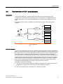
Introduction
PCS 7 supports system configurations where subcomponents are installed at different
locations, or even in different time zones. An example would be the installation of an
automation system and an operator station at different locations. The time must be
synchronized for the entire PCS 7 plant in order to optimize the sequence of all the
processes.
In PCS 7, the times of subcomponents are directly synchronized within a time zone. PCS 7
uses the "time synchronization" function to synchronize different time zones.
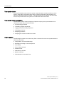
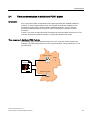
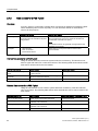
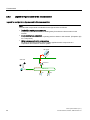
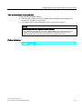
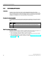
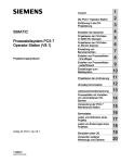
Time response in distributed PCS 7 plants
The following figure shows that time jumps may occur in process control systems (for
example, in the alarm lists) if there is no time synchronization. The processes do not run
synchronously:
2SHUDWRUVWDWLRQ
%HUOLQ
0HVVDJHV
$XWRPDWLRQV\VWHP
Time synchronization (V7.1)
Function Manual, 03/2009, A5E01216578-01
13
Fundamentals
2.4 Time synchronization in distributed PCS 7 plants
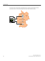
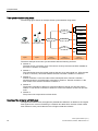
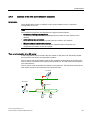
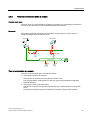
If the times for the components of a distributed PCS 7 plant are synchronized, all of the
processes will run in correct chronological order and will be archived correctly.
2SHUDWRUVWDWLRQ
%HUOLQ
0HVVDJHV
7LPHV\QFKURQL]DWLRQ
$XWRPDWLRQV\VWHP
14
Time synchronization (V7.1)
Function Manual, 03/2009, A5E01216578-01
Fundamentals
2.4 Time synchronization in distributed PCS 7 plants
Rules for configuring distributed PCS 7 plants
Since PCS 7 plants generally operate on the basis of UTC internally, their specific
components can be distributed on a global scale. In order to safeguard the interplay of
components - even across different time zones - please observe the following:
● Use UTC as the common time base in all PCS 7 plants. All plant components running
with UTC will display the same time after time synchronization.
● Set up a PC station as a PCS 7 Web server in all PCS 7 plants, using the PCS 7 OS web
option. This will allow you to access the PCS 7 Web servers of the PCS 7 plants via
multiple Web clients (in PCS 7: WebNavigator client or WebNavigator diagnostic client) at
the company's headquarters. You can convert the time display on the Web client to the
local system time. Please note the resulting time difference.
● If monitoring a PCS 7 plant in a different time zone on an OS, you can convert the time
displayed from UTC to the local system time using the OS control panel. Please note the
resulting time difference.
Note the following to prevent external synchronization:
NOTICE
Time message frames from external networks
Time message frames from external networks must be prevented from infiltrating
process control systems that are distributed across several networks or connected to
the Intranet or Internet.
Always connect the company network and the plants using network components that
enable separation of time signals, e.g. a router. Configure those network components so
that forwarding of time message frames is blocked.
Further information
● Section "Setting the time displayed (Page 51)"
● WinCC online help
Time synchronization (V7.1)
Function Manual, 03/2009, A5E01216578-01
15
Fundamentals
2.5 Central plant clock
2.5
Central plant clock
Using a central plant clock
You should always synchronize all Process Control Systems using either a precise time or a
standard time. In the case of PCS 7 plants, we recommend performing synchronization by
means of a central plant clock. The central plant clock manages the time centrally for the
entire plant and synchronizes all of the other plant components via their interfaces.
Recommendation:
Using the SICLOCK TC 400 as the central plant clock. The SICLOCK should be
synchronized with a standard time, e.g. using GPS or DCF 77, as this ensures that a correct
reference to the actual time is constantly available.
Standard time
The following standard times are typical for PCS 7 plants:
● GPS
The GPS signal is provided by a global satellite system.
● DCF 77
The DCF 77 signal is available in Germany and in certain parts of Europe using
corresponding radio signal receivers.
16
Time synchronization (V7.1)
Function Manual, 03/2009, A5E01216578-01
Fundamentals
2.6 Time levels for a PCS 7 plant (stratum)
2.6
Time levels for a PCS 7 plant (stratum)
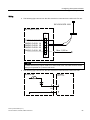
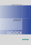
Introduction
Time synchronization of a system involves one component synchronizing the next
component by forwarding a time message frame. Forwarding time message frames will
result in time delays. You should make allowances for this fact when setting up a PCS 7
plant.
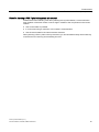
The following figure shows an example of the structure of a PCS 7 plant with several
domains:
8QLW
'RPDLQ
8QLW
8QLW
'RPDLQ
'RPDLQ
6,&/2&.
&HQWUDOSODQWFORFN
8QLW
8QLW
'RPDLQ
8QLW
8QLW
7LPHGLIIHUHQFH
Definition stratum
A PCS 7 plant component such as the central time clock (SICLOCK) receives the definitive
time from an external time source (e.g. a GPS signal) and forwards it to other components to
be synchronized. As a result, the SICLOCK is the time master for those components whose
time is determined in relation to the SICLOCK time. Components which are capable of
providing a time are considered time masters if other components use their time information.
All time masters form a hierarchy that consists of higher-level and lower-level time masters.
Relative position within this hierarchy is designated with a number; the "stratum". Multiple
time masters may be located within a single stratum. These time masters use the time
message frame at the same point in time to synchronize their own clock.
The stratum indicates the following:
● The number of time levels between the stratum in which the time master is located and
the stratum in which the time source (e.g. the GPS satellite) is located
● The time level where the components in a network are located
Time synchronization (V7.1)
Function Manual, 03/2009, A5E01216578-01
17
Fundamentals
2.6 Time levels for a PCS 7 plant (stratum)
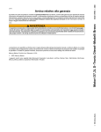
Time synchronization using strata
The following figure shows an example of time synchronization using strata:
8QLW
'RPDLQ
8QLW
8QLW
'RPDLQ
7LPHVLJQDO
*36'&)
'RPDLQ
8QLW
6,&/2&.
&HQWUDOSODQWFORFN
8QLW
'RPDLQ
8QLW
8QLW
/D\HU
/D\HU
/D\HU
7LPHPDVWHU
/D\HU
7LPHPDVWHU
/D\HU
7LPHPDVWHU
The above example shows time synchronization with the following structure:
● Stratum 0
The time source is an atomic clock. This atomic clock synchronizes the GPS satellites or
the DCF 77 senders, for example.
● Stratum 1
The central plant clock (SICLOCK) receives the time via a radio signal (e.g. GPS decoder
or DCF 77 receiver). SICLOCK transfers the time to domain controller 1 in stratum 2.
● Stratum 2
Domain controller 1 is the time slave of the central plant clock. Domain controller 1
transfers the time to several domain controllers in stratum 3. Domain controller 1 is the
time master of the domain controllers in stratum 3.
● Stratum 3
The domain controllers in stratum 3 synchronize the time of their own process units in
stratum 4. The domain controllers in stratum 3 are the time masters of their own process
units.
● Stratum 4
The process unit components are time slaves.
Meaning of the strata for a PCS 7 plant
The higher the stratum level, the higher the potential time difference in relation to the original
time signal source. As time forwarding in a network also takes time, the time of lower strata
time masters is more precise than the time of higher strata time masters.
18
Time synchronization (V7.1)
Function Manual, 03/2009, A5E01216578-01
Fundamentals
2.6 Time levels for a PCS 7 plant (stratum)
Rules for planning a PCS 7 plant taking strata into account
Please observe the following rules when planning time synchronization, to ensure that the
time deviation of the time master is not too high in relation to the components in the lowest
stratum:
● Use as few strata as possible.
● In most cases using a maximum of four strata is recommended.
● Use the same strata for the same structure elements.
When planning a PCS 7 plant to be synchronized, you should define exactly which hierarchy
would be best for receiving and forwarding the time.
Time synchronization (V7.1)
Function Manual, 03/2009, A5E01216578-01
19
Fundamentals
2.7 Time synchronization in PCS 7 - mode of operation
2.7
Time synchronization in PCS 7 - mode of operation
2.7.1
Time master and time slave
Introduction
To ensure that all Process Control System components operate with as precise a time as
possible, one system component must be the time source for all other components. The
precise time must be permanently available and be used for synchronization on a cyclical
basis (synchronization interval).
Time master
The component that provides the precise time within a bus system is referred to as the time
master. Only one component within a stratum can be the active time master.
Time slave
The time slaves within a bus system are components which receive or fetch their time from a
time master.
Cooperative time master
On OS servers, in the WinCC Editor "Time Synchronization" permanently defined computers
are set for the time synchronization.
The OS server works as a cooperative time master, i.e. the first active OS server on the
plant bus which does not receive time message frames on the plant bus automatically
switches to time "Master" mode. All other OS servers on the plant bus detect the time
message frame from the time master and automatically switch to time "slave" mode.
A cooperative time master does not have to belong to a redundant server.
Note
This setting applies both for the configuration with and without a central time master (central
plant clock e.g. SICLOCK TC 400).
20
Time synchronization (V7.1)
Function Manual, 03/2009, A5E01216578-01
Fundamentals
2.7 Time synchronization in PCS 7 - mode of operation
Function of the cooperative time master
The following process is initiated at the startup of a PC station that is configured as a
cooperative time master. A time message frame must be received within the wait time once
the PC station has powered up. The wait time amounts to four times the set synchronization
interval.
Possible response of cooperative time masters within the phase until the wait time has
expired:
● A cooperative time master that receives a time message frame from a different time
master within the wait time becomes a time slave.
● A cooperative time master that has not received a time message frame on expiry of the
wait time sends time message frames as the time master.
Within the set synchronization interval, all cooperative time masters check whether time
message frames have been received from the active time master on a cyclical basis. The
first cooperative master that detects three missing time message frames in succession
assumes the time master function. This ensures that only one time master exists.
Synchronization response
All time slaves and cooperative time masters on the terminal bus synchronize their internal
clock with the time message frames received. The time is synchronized as follows:
● Deviation ± 5 s:
Delay/acceleration of the internal clock
● Deviation > 5 s:
Immediate conversion (possible errors: Data packets sent off prior to the change will have
more recent time stamps than those sent off later)
Time synchronization (V7.1)
Function Manual, 03/2009, A5E01216578-01
21
Fundamentals
2.7 Time synchronization in PCS 7 - mode of operation
2.7.2
Time sources for a PCS 7 plant
Overview
In PCS 7 plants, it is necessary to define which component is capable of providing the plant
with a satisfactory time in terms of quality. You can use either internal or external time
sources for this purpose.
Suitability
External time source
Internal time source
External time sources provide an ultraprecise time and are suitable for all plant
configurations.
Internal time sources supply a continuous time signal. The
time provided does not have to match the local time or
Coordinated Universal Time (UTC).
Note:
Internal time sources are generally not approved for the
validation of processes.
Examples
GPS decoder
DCF 77 receiver
External NTP server
•
•
•
BIOS clock for a component without external time
synchronization.
Internal time source for a PCS 7 plant
Using an internal time source ensures system-wide time consistency. This time does not
have to agree with real UTC or with real local time. The following table shows which internal
time source can be used for the time master:
Internal time source
Requirement
Active time master
BIOS clock of a central plant
clock
The central plant clock is connected to a PCS
7 plant network.
Central plant clock
BIOS clock of a domain
controller
The computer to be synchronized belongs to a
Windows 2000/2003 domain.
Domain controller
BIOS clock of an OS server
The real time is not important for the project.
OS server
External time source for a PCS 7 plant
Using an external time source ensures system-wide time consistency. This time matches
UTC or local time. The following table shows which external time source can be used for the
time master:
External time source
Requirement
Active time master of the PCS 7 plant
DCF 77 or GPS signal
Radio signal synchronizes SICLOCK
Central plant clock
DCF 77 signal
The DCF 77 receiver is connected to a COM
interface of an OS server.
OS server with DCF 77 receiver
GPS signal
The GPS decoder is connected to a COM
interface of an OS server.
OS server with GPS decoder
NTP server
Internet connection
Domain controller
22
Time synchronization (V7.1)
Function Manual, 03/2009, A5E01216578-01
Fundamentals
2.7 Time synchronization in PCS 7 - mode of operation
2.7.3
Example of the time synchronization sequence
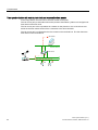
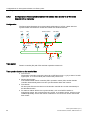
Introduction
The example below shows an example of time synchronization in PCS 7, based on
configurations for an OS.
Note
The individual components are identified in the figures below as follows:
• Dashed line starting at a component
Components with red dashed lines leading away from them are time masters in this
network.
• Arrow pointing to a component
Components to which an arrow is pointing are time slaves in this network.
• (M) at a component next to a bus system
An (M) at a component next to a bus system signifies that this component is a
cooperative time master for this bus system.
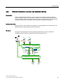
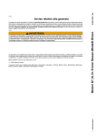
Time synchronization of an OS server
In the image below, the SICLOCK is the time master for the plant. The SICLOCK provides
the time for the OS servers and automation systems.
The OS server and the automation systems are configured as time slaves of the SICLOCK.
The OS server must be the time master on the terminal bus. The OS clients are time slaves
on the terminal bus.
The OS server is the cooperative time master on the plant bus. The OS server assumes the
time master function if the connection to the SICLOCK fails.
26FOLHQWV
7HUPLQDOEXV
6,&/2&.
26VHUYHU
0
3ODQWEXV
$6
Time synchronization (V7.1)
Function Manual, 03/2009, A5E01216578-01
$6
23
Fundamentals
2.7 Time synchronization in PCS 7 - mode of operation
Time synchronization with central plant clock and cooperative time master
In the image below, the SICLOCK is the time master for the plant.
The OS server pair (of redundant OS servers) and the automation systems are configured as
time slaves of the SICLOCK.
The OS server pair is the cooperative time master on the plant bus. One of the OS servers
assumes the time master function if the connection to the SICLOCK fails.
The OS server pair is configured as the time master on the terminal bus. The OS clients are
time slaves on the terminal bus.
26FOLHQWV
7HUPLQDOEXV
0
26VHUYHU
3ODQWEXV
6,&/2&.
$6
24
$6
Time synchronization (V7.1)
Function Manual, 03/2009, A5E01216578-01
Fundamentals
2.8 Network environment of a PCS 7 plant
2.8
Network environment of a PCS 7 plant
2.8.1
Overview
Network configuration for time synchronization in PCS 7
The sections that follow provide examples of network configurations for time synchronization
in PCS 7.
● Network environment within a domain (Page 27)
● Network environment within a work group (Page 28)
● Network environment in redundant, high-availability networks (Page 29)
● Network environment on separate networks with one central plant clock (Page 31)
Time synchronization (V7.1)
Function Manual, 03/2009, A5E01216578-01
25
Fundamentals
2.8 Network environment of a PCS 7 plant
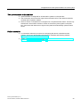
2.8.2
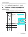
Legend for figures used in this documentation
Legend for configuration figures used in this documentation
Note
The individual components are identified in the figures below as follows:
• Dashed line starting at a component
Components with red dashed lines leading away from them are time masters in this
network.
• Arrow pointing to a component
Components to which an arrow is pointing are time slaves in this network. (Exception: (M)
on a component)
• (M) at a component next to a bus system
An (M) at a component next to a bus system signifies that this component is a
cooperative time master for this bus system.
26FOLHQWV
7HUPLQDOEXV
6,&/2&.
26VHUYHU
0
3ODQWEXV
$6
26
$6
Time synchronization (V7.1)
Function Manual, 03/2009, A5E01216578-01
Fundamentals
2.8 Network environment of a PCS 7 plant
2.8.3
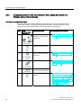
Network environment within a domain
Central plant clock
The SICLOCK TC 400 is particularly suitable for operation as a central plant clock within a
domain, as the SICLOCK has four independent Ethernet interfaces.
Structure
The following figure illustrates the recommended configuration for a PCS 7 plant in a
Windows domain with a central time clock:
6,&/2&.
26FOLHQWV
7HUPLQDOEXV
'&
26VHUYHU
0
3ODQWEXV
$6
$6
Time synchronization in a domain
The time is synchronized within a domain as follows:
● Time synchronization via plant bus
The plant bus is synchronized using the SICLOCK TC 400.
The synchronization mode depends on the CPU type used (with/without integrated
Ethernet interface).
● Time synchronization via terminal bus
The domain controllers are synchronized directly by the central plant clock using NTP
mode.
The domain controllers synchronize all domain members using the NTP method.
Time synchronization (V7.1)
Function Manual, 03/2009, A5E01216578-01
27
Fundamentals
2.8 Network environment of a PCS 7 plant
2.8.4
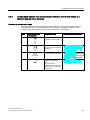
Network environment within a work group
Central plant clock
The SICLOCK TC 400 is suitable for operation as a central plant clock.
Structure
The following figure illustrates the recommended configuration for a PCS 7 plant in a work
group with a central time clock:
26FOLHQWV
7HUPLQDOEXV
6,&/2&.
26VHUYHU
0
26VHUYHU
0
3ODQWEXV
$6
$6
Time synchronization in a work group
The time is synchronized within a work group as follows:
● Time synchronization via plant bus
The plant bus is synchronized using the SICLOCK.
The OS servers and the automation systems receive the time from the central plant clock.
These are time slaves.
● Time synchronization via terminal bus
The OS clients receive their time from an OS server. OS clients only receive the time
from those OS servers from which they also loaded the server data.
28
Time synchronization (V7.1)
Function Manual, 03/2009, A5E01216578-01
Fundamentals
2.8 Network environment of a PCS 7 plant
2.8.5
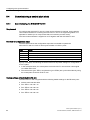
Network environment in redundant, high-availability networks
Introduction
Always install redundant networks in a PCS 7 plant as a precaution against production
losses caused by failures in the network connections. This will ensure that communication
via the redundant network will remain intact if an area of the terminal bus fails. The domain
controllers synchronize one another's time on the basis of Windows mechanisms.
Central plant clock
The SICLOCK TC 400 is suitable for operation as a central plant clock. The SICLOCK can
distribute the time signal directly to the plant networks.
Structure
The figure below illustrates the recommended configuration for a PCS 7 plant with a
redundant network structure (redundant terminal bus and plant bus):
'&
'&
7HUPLQDOEXV
26VHUYHU
0
0
26VHUYHU
VWDQGE\
3ODQWEXV
$6
Time synchronization (V7.1)
Function Manual, 03/2009, A5E01216578-01
$6
29
Fundamentals
2.8 Network environment of a PCS 7 plant
Time synchronization in redundant, high-availability networks
The time is synchronized as follows:
● SICLOCK supplies the exact time.
● The domain controller, terminal bus, and plant bus are synchronized by means of the
SICLOCK.
● The domain controllers act as time masters.
● The OS servers actively fetch the time from the domain controller.
30
Time synchronization (V7.1)
Function Manual, 03/2009, A5E01216578-01
Fundamentals
2.8 Network environment of a PCS 7 plant
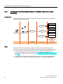
2.8.6
Network environment on separate networks with one central plant clock
Central plant clock
If you need to synchronize more than four networks using a single central plant clock (e.g.
SICLOCK TC 400) as the time source, you can use suitable switches to provide the time
within the individual networks. The switch is only used to distribute time message frames.
The remaining plant structure is identical to the relevant plant configuration.
Structure
The following figure illustrates the recommended configuration for a PCS 7 plant on separate
networks using a single SICLOCK as the central plant clock:
'&
6,&/2&.
6&$/$1&(
;(
7HUPLQDOEXV
26VHUYHU
26VHUYHU
3ODQW
3ODQW
3ODQW
3ODQW
Time synchronization on separate networks with one central plant clock
Note
You must ensure that each network only contains one time master for providing the time.
Separate message frame traffic between the networks.
Only use the switch to transfer the time signals from the central plant clock to the relevant
network.
The function for separating message frame traffic is dependent on the components used for
connecting the networks.
● Use of suitable SCALANCE switches (e.g. SCALANCE X414-3E)
Function: Access control
● Use of an OSM/ESM
Function: Port lock
Bidirectional communication is disabled if the corresponding function is activated.
Time synchronization (V7.1)
Function Manual, 03/2009, A5E01216578-01
31
Fundamentals
2.8 Network environment of a PCS 7 plant
Additional information
● (http://www.siemens-edm.de/fileadmin/Application_Notes/App_Note_0002.pdf)
● Configuration Manual Industrial Communication; Industrial Ethernet Switches;
SCALANCE X-300; SCALANCE X-400
● User Manual SIMATIC NET; Industrial Ethernet OSM/ESM; Industrial Ethernet OSM/ESM
32
Time synchronization (V7.1)
Function Manual, 03/2009, A5E01216578-01
Configurations for time synchronization of a PCS 7
plant
3.1
3
Overview of recommended configurations
Introduction
Various techniques are possible for time synchronization. The structure of a PCS 7 plant with
time synchronization requires careful planning in order to prevent any undesired results. Use
one of the following configurations to support you in planning your PCS 7 plant.
Recommended configurations
Plant type
Time synchronization in a
work group
Time synchronization in a
Windows domain
Recommend Configuration
ation
1
Time synchronization with a central time master
(Page 36)
2
Time synchronization without a central time master
(Page 38)
3
Time synchronization with a central time master
(Page 40)
4
Time synchronization without a central time master
(Page 42)
Configurations in Windows domains
Note
This document subdivides the recommended configurations for time synchronization in a
Windows domain (recommendations 3 and 4) on the basis of hierarchy levels. The sections
that follow shows the structure in configurations with different hierarchy levels:
• "Configuration of time synchronization with a central time master in a Windows domain
with one hierarchy level"
• "Configuration of time synchronization without a central time master in a Windows domain
with multiple hierarchies (Page 44)"
Time synchronization (V7.1)
Function Manual, 03/2009, A5E01216578-01
33
Configurations for time synchronization of a PCS 7 plant
3.2 Rules for time synchronization in PCS 7
3.2
Rules for time synchronization in PCS 7
Rules
● A network may only contain one active time master.
● Time synchronization with an external time source (e.g. GPS, DDF 77) is required if the
time within the PCS 7 plant is to match the local time.
● Central plant clocks (synchronized with an external time source wherever possible) are
high-grade internal time sources for PCS 7 plants.
● A time slave can be the time master for lower-level components and systems.
● Any domain controllers that are available in a network will synchronize all of the nodes in
this network. A synchronization cycle using domain controllers has a duration of eight
hours as standard. For reasons of precision, additional synchronization corrections using
integrated PCS 7 tools (WinCC time synchronization) are required. You can define an
interval at which the OS synchronizes its time with that of an external time source.
● The WinCC "time synchronization" application can be used to configure an OS server as
a time master, a cooperative time master, and a time slave.
● An OS server can be configured as a time master either with or without external time
synchronization.
● A direct time synchronization of the plant bus is necessary if the "high-precision time
stamping" function is used for selected signals in an automation system. The accuracy for
high-precision time stamping is insufficient if the central plant clock fails. The
chronological order of the signals displayed remains intact.
Time synchronization using NTP mode
The following components are synchronized using NTP mode:
● PC stations that are not operated as OS client or OS servers
● CPU types with integrated Ethernet interface: Please note the following restrictions:
– Maximum of 50 NTP requests/s
– When connecting to the OSM (6GK1105-0AA00 and 6GK1105-1AA00), please check
whether you have SIMATIC NET - Current edition 2000/025 (incompatibility with
tagged frames in Industrial Ethernet OSM networks)
(http://support.automation.siemens.com/WW/view/en/4247019).
– These CPU types may not be used in PCS 7 configurations with only a plant bus
(without a terminal bus).
Criteria for time synchronization in existing PCS 7 plants
Compare the configuration of your existing PCS 7 plant with the configurations outlined in
this documentation, and configure the time synchronization according to the present
configuration.
34
Time synchronization (V7.1)
Function Manual, 03/2009, A5E01216578-01
Configurations for time synchronization of a PCS 7 plant
3.2 Rules for time synchronization in PCS 7
V5-compatible mode
Note
Contact Customer Support if you want to use time synchronization in V5-compatible mode.
Further information
● Section "Time synchronization in distributed PCS 7 plants (Page 13)"
● Documentation Process Control System PCS 7; Released modules
Time synchronization (V7.1)
Function Manual, 03/2009, A5E01216578-01
35
Configurations for time synchronization of a PCS 7 plant
3.3 Configurations for time synchronization in a work group
3.3
Configurations for time synchronization in a work group
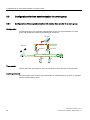
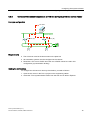
3.3.1
Configuration of time synchronization with central time master in a work group
Configuration
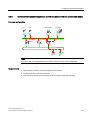
The following figure is a schematic representation of how time synchronization of a work
group with central time master should ideally be configured.
26FOLHQWV
7HUPLQDOEXV
6,&/2&.
26VHUYHU
0
26VHUYHU
0
3ODQWEXV
$6
$6
Time master
Central plant clock (SICLOCK TC 400, SICLOCK TM or SICLOCK TS) on the plant bus
Central plant clock
The central plant clock is either synchronized with an external signal (e.g. GPS), or operates
with the internal realtime clock.
36
Time synchronization (V7.1)
Function Manual, 03/2009, A5E01216578-01
Configurations for time synchronization of a PCS 7 plant
3.3 Configurations for time synchronization in a work group
Time synchronization on the plant bus
● Time master is the SICLOCK connected to the plant bus as the central plant clock. It
sends a high-precision broadcast time signal on the plant bus. Time synchronization is
set in SIMATIC mode.
● The OS servers are configured as what are known as cooperative time masters. If the
SICLOCK no longer sends a time signal, then an OS server becomes active time master
and then sends time signals itself on the plant bus, as a replacement.
● Configuring the automation systems:
– The automation system with standard CPU (without integrated Ethernet interface) is
configured for operation as a time slave.
– The automation system with integrated Ethernet interface is configured for operation
as a time master.
● The SIMATIC PCS 7 BOX and SIMATIC PCS 7 AS RTX are configured (see the table
below). Time synchronization is set in NTP mode.
Time synchronization on the terminal bus
● During the runtime of a PCS 7 project, an OS server adopts the time signal received from
the plant bus. This OS server sets the system time of the other OS servers. You make the
settings in the WinCC "Time Synchronization" editor.
● The OS clients are configured as time slaves and receive their time signal from an OS
server, from where server data is downloaded.
● PC stations without WinCC time synchronization, such as a BATCH PC or engineering
station, are synchronized using a DCF 77 reception service, which must be installed
separately. An OS server can be operated as a time master.
Further information
● Section "Configuration steps for time synchronization with central time master in a work
group (Page 56)"
Time synchronization (V7.1)
Function Manual, 03/2009, A5E01216578-01
37
Configurations for time synchronization of a PCS 7 plant
3.3 Configurations for time synchronization in a work group
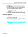
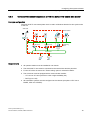
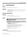
3.3.2
Configuration of time synchronization without central time master in a work group
Configuration
The following figure schematically shows the recommended configuration of a PCS 7 plant
with time synchronization in a work group without central time master:
26FOLHQWV
7HUPLQDOEXV
26VHUYHU 0
26VHUYHU 0
3ODQWEXV
$6
$6
Time master
The OS servers are the time masters for the PCS 7 plant.
Time synchronization on the terminal bus
The OS servers are configured for operation as time masters on the terminal bus. One OS
server transmits the time message frame to the plant bus. The OS clients are configured for
operation as time slaves. They fetch the time from the OS server.
38
Time synchronization (V7.1)
Function Manual, 03/2009, A5E01216578-01
Configurations for time synchronization of a PCS 7 plant
3.3 Configurations for time synchronization in a work group
Time synchronization on the plant bus
Configuring the automation systems:
● The automation system with standard CPU (without integrated Ethernet interface) is
configured for operation as a time slave.
● The SIMATIC PCS 7 BOX and SIMATIC PCS 7 AS RTX are configured.
NOTICE
Automation system with integrated Ethernet interface
The use of these CPU types in this PCS 7 configuration and in configurations with a
combined plant and terminal bus is not permitted. These CPU types can only be
synchronized via NTP mode. We recommend using a central plant clock.
Further information
● Section "Configuration steps for time synchronization without a central time master in a
work group (Page 57)"
Time synchronization (V7.1)
Function Manual, 03/2009, A5E01216578-01
39
Configurations for time synchronization of a PCS 7 plant
3.4 Configuration for time synchronization in a Windows domain
3.4
Configuration for time synchronization in a Windows domain
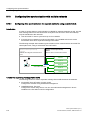
3.4.1
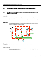
Configuration of time synchronization with central time master in a Windows
domain with a hierarchy
Introduction
In a Windows domain, you should synchronize the terminal bus and the plant bus directly
using the central plant clock.
The SICLOCK TC 400 is recommended as the central plant clock as it has four independent
Ethernet interfaces.
Configuration
The following figure illustrates the recommended configuration for a PCS 7 plant in a
Windows domain with a central time master:
6,&/2&.
'&
'&
26FOLHQWV
%$7&+VWDWLRQ
7HUPLQDOEXV
26VHUYHU
26VHUYHU
(QJLQHHULQJ
6WDWLRQ
0
0
3ODQWEXV
$6
$6
Time master
The SICLOCK central plant clock on the plant bus and the terminal bus
Central plant clock
The central plant clock is either synchronized with an external signal (e.g. GPS), or operates
with the internal realtime clock.
40
Time synchronization (V7.1)
Function Manual, 03/2009, A5E01216578-01
Configurations for time synchronization of a PCS 7 plant
3.4 Configuration for time synchronization in a Windows domain
Time synchronization on the terminal bus
● Active time master:
The time master is the domain controller (DC), which is parameterized as the main
structure master and/or the PDC emulator (usually the first domain controller installed).
● Time source:
The domain controller receives the time from the SICLOCK central plant clock. The
SICLOCK TC 400 is connected to the terminal bus by means of an Ethernet connection.
The SICLOCK TC 400 central plant clock synchronizes the domain controllers by means
of the NTP method.
● All other plant PCs automatically become time slaves of the domain controller (PDC
emulator) due to their membership in the Windows domain.
● The Windows time service (w32tm) synchronizes the date and time of all computers in a
Windows domain. Since the Windows-internal time synchronization only takes place
every eight hours, the OS servers are also configured for operation as time slaves of the
domain controller (PDC emulator) using the WinCC time synchronization function.
The PDC emulator is an operation master role of a domain controller. The domain
controller with this operation master role synchronizes the members of the Windows
domain every 8 hours.
● Passive time master:
If the authenticated domain controller (PDC operation master) fails, another domain
controller automatically takes over time synchronization within the network.
● The OS clients are configured as time slaves of the OS servers connected and receive
their time signal via the terminal bus.
● PC stations without WinCC time synchronization, such as a BATCH PC or engineering
station, are synchronized using a DCF 77 reception service, which must be installed
separately. As time master one of the domain controllers or an OS server is possible
here.
Time synchronization on the plant bus
● The time master for the plant bus is the SICLOCK connected to the plant bus as the
central plant clock. It sends a high-precision broadcast time signal to the plant bus
(SIMATIC mode).
The OS servers are configured as what are known as cooperative masters. If the AS no
longer sends a time signal then an OS server becomes time master and then sends time
signals itself on the plant bus, as a replacement.
● Time synchronization is configured for all automation systems on the plant bus.
Further information
● Section "Configuration steps for time synchronization with a central time master in a
Windows domain with a hierarchy (Page 58)"
● For information on configuring authorizing time servers in Windows Server 2003, refer to
the relevant Microsoft reference material at the following Internet address:
http://support.microsoft.com, subject: Configuring an authorizing time server in Windows
Server 2003 (http://support.microsoft.com/kb/816042/en)
Time synchronization (V7.1)
Function Manual, 03/2009, A5E01216578-01
41
Configurations for time synchronization of a PCS 7 plant
3.4 Configuration for time synchronization in a Windows domain
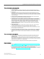
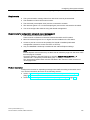
3.4.2
Configuration of time synchronization with central time master in a Windows
domain with a hierarchy
Configuration
The figure below illustrates the recommended configuration of a PCS 7 plant with time
synchronization and without a central time master in a Windows domain.
'&
'&
(QJLQHHULQJ
6WDWLRQ
%$7&+VWDWLRQ
26VHUYHU
0
26VHUYHU
26FOLHQWV
7HUPLQDOEXV
0
3ODQWEXV
$6
$6
Time master
Domain controller (DC) with PDC emulator operation master role
Time synchronization on the terminal bus
● Time source:
The domain controller receives the time via an NTP time server, e.g. by means of a radio
signal (DCF 77 or GPS module) that contains the precise time.
● Passive time master:
If the authenticated domain controller (PDC operation master) fails, another domain
controller automatically takes over time synchronization within the network.
● Time slaves:
All other plant PCs are time slaves of the domain controller due to their membership in
the Windows domain.
● PC stations without WinCC time synchronization, such as a BATCH station or
engineering station, are synchronized using a DCF 77 reception service, which must be
installed separately. One of the domain controllers or an OS server can be used as the
time master.
42
Time synchronization (V7.1)
Function Manual, 03/2009, A5E01216578-01
Configurations for time synchronization of a PCS 7 plant
3.4 Configuration for time synchronization in a Windows domain
Time synchronization on the plant bus
● Synchronization is configured for all automation systems on the plant bus.
● The OS servers receive the time signal via the terminal bus from the authorized domain
controller (PDC operation master).
● Each OS server on the plant bus is configured as a cooperative time master. The OS only
activates the "time master" function if it does not receive any time signals on the plant
bus. OS servers that detect a time signal on the plant bus automatically operate as time
slaves.
Further information
● For information about the procedure for configuring the domain controllers as time
masters, refer to the relevant Microsoft reference material at the following address:
(http://support.microsoft.com/kb/816042/en-us)
● Section "Configuration steps for time synchronization without a central time master in a
Windows domain with a hierarchy (Page 59)"
Time synchronization (V7.1)
Function Manual, 03/2009, A5E01216578-01
43
Configurations for time synchronization of a PCS 7 plant
3.4 Configuration for time synchronization in a Windows domain
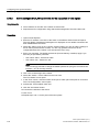
3.4.3
Configuration of the time synchronization in a Windows domain with multiple
hierarchies
Configuration
The following figure shows a sample configuration for time synchronization in a Windows
domain with multiple hierarchies:
8QLW
'RPDLQ
8QLW
8QLW
'RPDLQ
'RPDLQ
7LPHVLJQDO
6,&/2&.
*36'&) &HQWUDOSODQWFORFN
8QLW
8QLW
'RPDLQ
'RPDLQ
URRWGRPDLQ
KLHUDUFK\OHYHO
KLHUDUFK\OHYHO
KLHUDUFK\OHYHO
Rules
In order to avoid time jumps, please observe the following rules when setting up the
hierarchy for the PCS 7 plants within a Windows domain that contains multiple hierarchies:
● All identical structures must be assigned to the same levels in a Windows domain that
contains multiple hierarchy levels. This will prevent unwanted time differences.
For further information, refer to the section titled "Time levels for a PCS 7 plant (stratum)
(Page 17)".
● Create only one hierarchy level under the root domain. Set up any additional Windows
domains you may require on the same hierarchy level as the existing subdomains.
44
Time synchronization (V7.1)
Function Manual, 03/2009, A5E01216578-01
4
Planning time synchronization
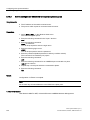
4.1
Selecting the time master
Selecting the time master
On a time-synchronous PCS 7 plant, you require a time master to which the additional plant
components can be synchronized. The table below lists the components that are used as
time masters, depending on the network environment:
Time master
SICLOCK
OS server
With time
source ...
Provides the
time via ...
Time master
forwards the time to...
Forwards the time to ...
Central clock:
Not
synchronized,
or
synchronized
(e.g. via GPS
or DCF 77)
Terminal bus
Domain controller
-
Terminal bus
OS server
Terminal bus with OS servers and
OS clients
Plant bus
Automation systems
-
- BIOS clock
Terminal bus
OS clients
- GPS
Plant bus
CP of the OS servers that are
active time masters
Automation systems
Terminal bus
OS server
OS clients
- DCF 77
Domain controllers - GPS
- DCF 77
Plant bus, including the automation
systems
- NTP server
PC
- BIOS clock
- GPS
All OS servers as
time masters
- DCF 77
- NTP
Time synchronization (V7.1)
Function Manual, 03/2009, A5E01216578-01
45
Planning time synchronization
4.2 Selecting the central plant clock
4.2
Selecting the central plant clock
Introduction
You should always synchronize all automation processes using a standard time. In the case
of PCS 7 plants, we recommend performing synchronization by means of a central plant
clock. The central plant clock controls the time for the entire PCS 7 plant, and synchronizes
all other plant components via their interfaces.
A GPS or DCF 77 signal should be used as the time source for the central plant clock.
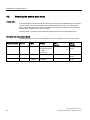
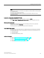
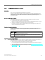
Selecting the central plant clock
The following table shows which central plant clocks are offered by the SICLOCK system:
Central plant clock Ethernet
Inputs
Outputs
GPS
decoders
DCF 77
receivers
SICLOCK TC 400
2 x digital
2x digital 24V
GPS1000 (GPSDEC)
DCFRS industry
version
4x RJ45 or ITP
1x digital RS422/5V
1 x alarm
1x warning
SICLOCK TM
RJ45 or ITP
2 x digital
8 x digital
GPS1000 (GPSDEC)
DCFRS industry
version
SICLOCK TS
RJ45 or ITP
1 x IRIG A+B
1 x digital
1 x IRIG A+B
3 x digital
GPS1000
DCFRS industry
version
46
Time synchronization (V7.1)
Function Manual, 03/2009, A5E01216578-01
Planning time synchronization
4.2 Selecting the central plant clock
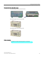
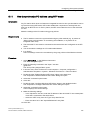
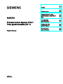
Representation of the SICLOCK variants
The following figures show a SICLOCK TC 400:
The following figure shows a SICLOCK TM:
The following figure shows a SICLOCK TS:
Further information
● Information concerning central plant clocks on the Internet:
(http://www.siemens-edm.de/anlagen_zentraluhren.0.html?&L=2)
Time synchronization (V7.1)
Function Manual, 03/2009, A5E01216578-01
47
Planning time synchronization
4.2 Selecting the central plant clock
48
Time synchronization (V7.1)
Function Manual, 03/2009, A5E01216578-01
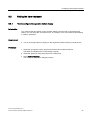
Configuring time synchronization
5.1
5
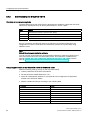
Introduction
Components
To synchronize the time of your plant, it is necessary to configure all network nodes for time
synchronization. To do this configure the following components depending on configuration:
● Time receivers
If synchronizing the time using an external time source, you must configure the time
recipient for a central plant clock.
● Operator station
Configure the OS server(s) and the OS clients.
● Communication modules
Configure the CPs for time synchronization.
● Automation system
Configure the CPU and the communications processors of the automation system (CP
443-1, CP 443-5 Extended).
● Additional plant components
The following components should be included in the time synchronization as needed:
– SIMATIC BATCH
– SIMATIC Route Control
– SIMATIC PCS 7 BOX
– SIMATIC IT
– Engineering station
Time synchronization (V7.1)
Function Manual, 03/2009, A5E01216578-01
49
Configuring time synchronization
5.1 Introduction
Time synchronization modes
The time synchronization mode is activated when configuring time synchronization.
The following options for synchronizing the time of network components are used in PCS 7:
● Synchronization by means of WinCC time synchronization
The "WinCC time synchronization" application is used to synchronize the time of the
following components:
– PC stations on which the software for an OS server or OS client is installed
– Automation systems in SIMATIC PCS 7 BOX RTX
● SIMATIC mode
SIMATIC mode is used for time synchronization of automation systems on the plant bus
(exception: Automation systems with integrated Ethernet interface;
SIMATIC PCS 7 BOX RTX and SIMATIC PCS 7 AS RTX).
● NTP mode
NTP mode is used for time synchronization of the following components:
– Domain controller (DC)
– Automation systems with integrated Ethernet interface
(order numbers: 6ES7 414-3EM05-0AB0 and 6ES7 416-3ER05-0AB0)
– PC stations on which the software for an OS server or OS client has not been
installed, and which are not synchronized using the DCF 77 reception service.
Typical application for: SIMATIC BATCH, SIMATIC Route Control, engineering station
● Synchronization by means of DCF 77 reception service
The "DCF 77 reception service" application is used to synchronize the time of the
following components:
– PC stations on which the software for an OS server or OS client has not been
installed, and which are not synchronized using NTP mode.
Typical application for: SIMATIC BATCH, SIMATIC Route Control, engineering station
50
Time synchronization (V7.1)
Function Manual, 03/2009, A5E01216578-01
Configuring time synchronization
5.2 Setting the time displayed
5.2
Setting the time displayed
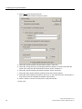
5.2.1
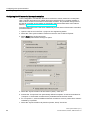
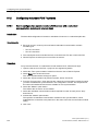
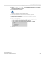
How to configure the operator station display
Introduction
You configure the time display for the operator station process mode on the engineering
station. You can select the "Local time zone", for example, in the "Time base for time display
in runtime" parameter.
Requirement
● You must configure the time display on the engineering station before you load the OS.
Procedure
1. Select the "[Computer name]" object from the tree view in WinCC Explorer.
The detail view displays the corresponding computer.
2. Select the "[Name of computer]" object in the detail view.
3. Select Edit > Properties.
The "Computer properties" dialog box opens.
Time synchronization (V7.1)
Function Manual, 03/2009, A5E01216578-01
51
Configuring time synchronization
5.2 Setting the time displayed
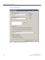
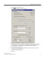
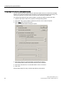
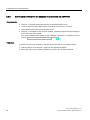
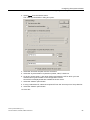
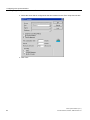
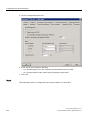
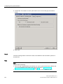
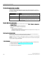
4. Select the "Parameters" tab.
Figure 5-1
52
Example: Setting for the "Local time zone"
Time synchronization (V7.1)
Function Manual, 03/2009, A5E01216578-01
Configuring time synchronization
5.2 Setting the time displayed
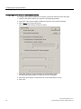
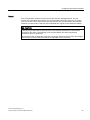
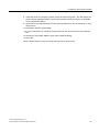
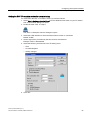
5. Select "The PLC is is set to coordinated universal time (UTC) (preferred setting)" check
box in the "PLC clock setting" group.
6. Select the required time mode from the "Time base for time display in runtime" drop-down
list box.
– If you want to set the time for migrated projects: "Time zone of the server (migrated
projects)"
– If you want to set the local time with daylight saving time and standard time: "Local
time zone"
– If you want to set UTC: "Coordinated Universal Time (UTC)"
The time zone is only important for the display in process mode. Internally, UTC is
used exclusively; in archives, for example.
7. Select the required format in the "Central date and time formatting" group. This formatting
affects the date and time display within the context of process control.
– Date in the configured format: "Configure individual components"
– Date in accordance with ISO 8601: "ISO8601-Swap format to all components"
8. Click "OK".
Time synchronization (V7.1)
Function Manual, 03/2009, A5E01216578-01
53
Configuring time synchronization
5.2 Setting the time displayed
5.2.2
How to convert the local time zone and daylight saving time parameters
Introduction
You can convert the time displayed on the OS in process mode.
Rules
● If operating a plant across several time zones with different daylight saving time and
standard time settings, you should also use the harmonized UTC time for the time display
on the operator station. You therefore have a uniform basis for process analysis at all
plant units.
● You can configure the switch to daylight saving time or point in time for the switch for
each specific country. PCS 7 always handles internal functions on the basis of UTC.
Therefore, any conversion to daylight saving time or to a different local time does not
have any impact on the internal functions of PCS 7.
If the time display of the operator station is set to the local time of specific countries, with
automatic conversion of daylight saving time and standard time, the time is automatically
converted at the correct date and time.
Requirements
● It must be possible to operate the operating system environment.
● You must make the settings directly on the OS.
Procedure
To change the operator station to display daylight saving time and standard time, follow
these steps:
1. Go to the Window Start menu on the OS and select Start > Settings > Control panel.
2. Double-click the "Date and Time" icon.
3. Select the "Time Zone" tab.
Ensure that the time zone displayed in your list field is appropriate for your area
54
Time synchronization (V7.1)
Function Manual, 03/2009, A5E01216578-01
Configuring time synchronization
5.2 Setting the time displayed
4. Select the check box "Automatically adjust clock for daylight saving changes".
5. Click "OK".
Result
All time information for the operator station will be output in the local time of the selected
time zone, including daylight saving time changes, and it will be converted at the correct
point in time.
Time synchronization (V7.1)
Function Manual, 03/2009, A5E01216578-01
55
Configuring time synchronization
5.3 Overview of configuration steps, depending on the configuration
5.3
Overview of configuration steps, depending on the configuration
5.3.1
Configuration steps for time synchronization with central time master in a work
group
Overview of configuration steps
The table below shows the configuration steps required for time synchronization with a
central time master in a work group, including a reference to the sections of this
documentation that provide a description of these steps:
Step
Time
synchronization
components
1
Clocks
Configuration steps
Operating instructions in section:
Clocks - connection,
installation, and parameter
assignment
"Commissioning a central plant clock
(Page 60)"
(e.g. SICLOCK with GPS
or DCF 77)
Parameterizing automation •
systems as time slaves
2
•
AS
3
CP
4
CPU without integrated Ethernet
interface: "How to set time
synchronization on an AS for SIMATIC
mode (Page 99)"
CPU with integrated Ethernet interface:
"How to set time synchronization on an
AS for NTP mode (Page 105)"
SIMATIC PCS 7 BOX and SIMATIC
PCS 7 AS RTX: "Configuring time
synchronization for the SIMATIC PCS 7
BOX and SIMATIC PCS 7 AS RTX
(Page 109)"
Assigning parameters for
CP for the plant bus
•
Parameter assignment for
an OS server as
cooperative master
"How to set time synchronization on an OS
in a work group with central time master
(Page 72)"
OS server
Parameter assignment for
redundant OS servers
5
OS server
6
Parameter assignment for
OS clients
OS clients
56
Time synchronization (V7.1)
Function Manual, 03/2009, A5E01216578-01
Configuring time synchronization
5.3 Overview of configuration steps, depending on the configuration
5.3.2
Configuration steps for time synchronization without a central time master in a
work group
Overview of configuration steps
The table below shows the configuration steps required for time synchronization without a
central time master in a work group, including a reference to the sections of this
documentation that provide a description of these steps:
Step
Time
synchronization
components
1
Configuration steps
Operating instructions in section:
Parameterizing all
automation systems
•
AS
•
•
CPU without integrated Ethernet
interface: "How to set time
synchronization on an AS for SIMATIC
mode (Page 99)"
CPU with integrated Ethernet interface:
"How to set time synchronization on an
AS for NTP mode (Page 105)"
SIMATIC PCS 7 BOX and SIMATIC
PCS 7 AS RTX: "Configuring time
synchronization for the SIMATIC PCS 7
BOX and SIMATIC PCS 7 AS RTX
(Page 109)"
Parameterizing OS servers "How to set time synchronization on an OS
in a work group without central master."
as time masters
(Page 75)"
2
OS servers
Parameterizing OS clients
3
OS clients
Time synchronization (V7.1)
Function Manual, 03/2009, A5E01216578-01
57
Configuring time synchronization
5.3 Overview of configuration steps, depending on the configuration
5.3.3
Configuration steps for time synchronization with a central time master in a
Windows domain with a hierarchy
Overview of configuration steps
The table below shows the configuration steps required for time synchronization with a
central time master in a Windows domain with a hierarchy, including a reference to the
sections of this documentation that provide a description of these steps:
Step
Time
synchronization
components
1
Configuration steps
Operating instructions in section:
Clocks - connection,
installation, and parameter
assignment
•
Parameterizing domain
controllers as time masters
See Microsoft reference material
Parameterizing PCs without
WinCC time synchronization
via DCF 77
•
"How to make DCF 77 Client Service
settings on a PC station without OS
(Page 93)"
Parameterizing OS clients
•
"How to set time synchronization on
an OS in a domain with central time
master. (Page 79)"
•
"How to set time synchronization on
an AS for SIMATIC mode (Page 99)."
"How to set time synchronization on
an AS for NTP mode (Page 105)"
"Configuring time synchronization for
the SIMATIC PCS 7 BOX and
SIMATIC PCS 7 AS RTX
(Page 109)"
"Commissioning a central plant clock
(Page 60)"
SICLOCK with
GPS or DCF 77
2
DC
3
PC, e.g. BATCH
station
4
OS clients
5
OS servers
6
Parameterizing OS servers
as cooperative time masters
Parameterizing automation
systems
AS
•
•
58
Time synchronization (V7.1)
Function Manual, 03/2009, A5E01216578-01
Configuring time synchronization
5.3 Overview of configuration steps, depending on the configuration
5.3.4
Configuration steps for time synchronization without a central time master in a
Windows domain with a hierarchy
Overview of configuration steps
The table below shows the configuration steps required for time synchronization without a
central time master in a Windows domain with a hierarchy, including a reference to the
sections of this documentation that provide a description of these steps:
Step
Components for time
synchronization
1
Configuration steps
Operating instructions in section:
Parameterizing domain
controllers as time masters
See Microsoft reference material
DC
2
Parameterizing PCs without •
WinCC time synchronization
via DCF 77
"How to make DCF 77 Client
Service settings on a PC
station without OS (Page 93)"
Parameterizing OS servers •
as cooperative time masters
"How to set time
synchronization on an OS in a
domain without central time
master. (Page 85)"
•
Parameterizing automation
systems as time slaves
Note:
CPU types with an
integrated Ethernet interface
cannot be used in this plant
configuration.
"Configuring time
synchronization on an AS
(Page 99)"
PC
3
OS server
4
AS
Time synchronization (V7.1)
Function Manual, 03/2009, A5E01216578-01
59
Configuring time synchronization
5.4 Commissioning a central plant clock
5.4
Commissioning a central plant clock
5.4.1
Commissioning the SICLOCK TC 400
Requirement
To configure the SICLOCK TC 400, the Java runtime software is required. Only install the
Java runtime software for accessing the SICLOCK TC 400 on an engineering station or a
separate PC station (not on components that are involved in process mode).
The Java runtime software is supplied on a CD together with the SICLOCK TC 400.
Overview of configuration steps
The table below shows the configuration steps that are needed to operate the
SICLOCK TC 400 as a clock for time synchronization of a PCS 7 plant:
Step
What?
1
Wire the time receiver to the SICLOCK TC 400
2
Parameterize the time receiver
3
Set the basic parameters on the SICLOCK TC 400
4
Connect the SICLOCK TC 400 to the PCS 7 plant
5
Configure the SICLOCK TC 400 on a plant-specific basis via Internet Explorer
By way of example, the following sections list the most important settings for configuration in
a PCS 7 plant:
● In the examples below, the central plant clock SICLOCK TC 400 receives a time signal
via a GPS radio clock.
● The terminal bus (port: ETH1) and plant bus (port: ETH2) are synchronized directly using
the central plant clock SICLOCK TC 400.
Factory settings of the SICLOCK TC 400
The SICLOCK TC 400 is supplied with the following default settings for the Ethernet ports:
● Subnet mask 255.255.255.0
● Port: ETH1: 192.168.1.10
● Port: ETH2: 192.168.2.20
● Port: ETH3: 192.168.3.30
● Port: ETH4: 192.168.4.40
60
Time synchronization (V7.1)
Function Manual, 03/2009, A5E01216578-01
Configuring time synchronization
5.4 Commissioning a central plant clock
Set the basic parameters on the SICLOCK TC 400
The direct parameter settings on the SICLOCK TC 400 are required as basic parameters for
connection to the network only.
1. Press the "Setup" button on the SICLOCK TC 400.
2. Enter the password and then press "OK".
The parameter list is displayed:
– Language (select German or English)
– ETH1 IP address
– ETH1 IP subnet
– ETH1 IP gateway
– ETH2 IP address
– ETH2 IP subnet
– ETH2 IP gateway
– ETH3 IP address
– ETH3 IP subnet
– ETH3 IP gateway
– ETH4 IP address
– ETH4 IP subnet
– ETH4 IP gateway
– Acknowledge events
– Version (for information only)
3. Perform the settings for the required Ethernet connections.
Time synchronization (V7.1)
Function Manual, 03/2009, A5E01216578-01
61
Configuring time synchronization
5.4 Commissioning a central plant clock
Configuring the SICLOCK TC 400
1. Connect the SICLOCK TC 400 to the network.
(For example, connect Ethernet port ETH1 of the SICLOCK TC 400 to the terminal bus)
2. Open Internet Explorer on a PC. Enter the network address of the SICLOCK TC 400 in
the input field (e.g. Port:ETH1 = address 192.168.1.10).
3. In the configuration portal area, click the "SICLOCK TC 400 configuration tool" link.
The configuration tool opens.
4. Select Data Transfer > Download parameters from device from the configuration tool
menu.
5. Configure the SICLOCK TC 400 in accordance with the table below.
Note
The identifier "= ..." in the "Parameters and setting" column represents the "plant-specific
setting".
Table 5- 1
Settings
Folder
Parameters and setting
Description
Time
Time zone = ...
(optional = ...)
"Time zone" parameter,
"Offset between UTC and zone time"
entry
Network settings
e.g. Port: Ethernet 1 (ETH1)
• IP adapter 1 / IP address = ...
• IP adapter 1 / subnet mask = ...
Enter the plant-specific network
address(es). Configure the network
connections ETH2, ETH3 and ETH4 in
the same way.
SIMATIC mode
e.g. Port: Ethernet 2 (ETH2)
• Mode = PCS 7-compatible mode, every 10 seconds
• Send condition = "No condition"
• Target address = "FF:FF:FF:FF:FF:FF"
SIMATIC mode is available at all four
Ethernet ports.
NTP server
• Operation = On
• Mode = 10 s
• Multicast address = ...
The NTP server is available at all four
Ethernet ports. Requirements:
SICLOCK TC 400 is synchronized.
Display:
• Language = ...
• Time / Time base = ...
•
NTP server
Display
62
Note: Only activate SIMATIC mode for
the ETHERNET ports on the plant bus.
A synchronization time of 10 seconds is
recommended for PCS 7.
A broadcast telegram is sent to all nodes
on this network.
Multicast address: Enter the plantspecific IP address for NTP time
synchronization.
•
Language setting:
German or English
Time base:
Local time, UTC or atomic time (TAI)
Select the time that will appear on the
display.
Time synchronization (V7.1)
Function Manual, 03/2009, A5E01216578-01
Configuring time synchronization
5.4 Commissioning a central plant clock
Note
For the purpose of time synchronization on the plant bus, activate SIMATIC mode separately
for each Ethernet port.
The settings can be password-protected.
You will find additional information on this topic in the SICLOCK; SICLOCK TC 400
Operating Instructions.
Loading the configuration to the SIMATIC TC 400
This step is only necessary if the configuration is carried out offline.
Select Data Transfer > Download parameters to device from the configuration tool menu.
Backing up the configuration
To save the set SICLOCK parameters and event display (archive) to a file, select the
following menu command: File > Save.
The data (parameter settings and archive) are saved in U600 format.
Connecting the time receiver
To ensure that the central plant clock is in constant receipt of an accurate time, it should be
synchronized with a time receiver.The following time receivers are recommended in PCS 7:
● SICLOCK GPS1000
● SICLOCK GPSDEC
● SICLOCK DCFRS Industry version
Additional information
● Section "Rules for time synchronization in PCS 7 (Page 34)"
● Section "Commissioning the DCF 77 receiver (Page 69)"
● Section "Commissioning GPS receivers (Page 66)"
● SICLOCK; SICLOCK TC 400 Operating Instructions
Time synchronization (V7.1)
Function Manual, 03/2009, A5E01216578-01
63
Configuring time synchronization
5.4 Commissioning a central plant clock
5.4.2
Commissioning the SICLOCK TM/TS
Overview of commissioning tasks
The table below shows the commissioning tasks that are needed to operate the SICLOCK
TM/TS as a central plant clock for time synchronization in a PCS 7 plant:
Step
What?
1
Wire the time receiver to the SICLOCK TM/TS
2
Parameterize the time receiver
3
Assign parameters to the SICLOCK TM/TS (SIMATIC or NTP mode)
4
Connect the SICLOCK TM/TS to the PCS 7 plant
By way of example, the following sections provide the most important settings for the
configuration in a PCS 7 plant where the automation systems are synchronized using
SIMATIC mode.
Note
Siclock Remote parameterization software
You can use the "Siclock Remote" parameterization software to make the settings for the
SICLOCK TM and SICLOCK TS central plant clocks. This software is available on the
Internet together with a set of parameter assignment instructions: http://www.siemensedm.de (http://www.siemens-edm.de/anlagen_zentraluhren.0.html?&L=2).
Assigning parameters to the SICLOCK TM/TS for SIMATIC mode
Make the following settings directly on the SICLOCK TM/TS:
1. Call the parameters of the SICLOCK TM/TS.
2. Set the parameter 338/6A Ethernet to "On."
3. Select an unassigned IP address on your plant bus and configure this at parameter
343/6A of the SICLOCK TM/TS.
4. Make the additional settings according to the following table:
64
Parameter
Value
341/6A "Source addr. part 0"
<MAC address>
342/6A "Source addr. part 1"
<MAC address>
339/6A
"LAN connection"
350/6B "Addr. 1 protocol"
"Layer 2 - S5"
351/6B "Send addr. 1"
"Each second"
353/6B "Addr. 1 dest. 0"
"FFFFFF"
354/6B "Addr. 1 dest. 1"
"FFFFFF"
338/6A "Ethernet"
"On" or "synchronized"
Time synchronization (V7.1)
Function Manual, 03/2009, A5E01216578-01
Configuring time synchronization
5.4 Commissioning a central plant clock
Assigning parameters to the SICLOCK TM/TS for NTP mode
Make the settings directly on the SICLOCK TM/TS.
1. Call the parameters of the SICLOCK TM/TS.
2. Set parameter 338/6A Ethernet to "On."
3. Select an unassigned IP address on your plant bus and configure this at parameter
343/6A of the SICLOCK TM/TS.
4. Enter "any/unicast" for parameter 550/6F "SNTP-Server".
Note
Check the parameter settings if necessary. Please note the following:
• If you are using a different central plant clock, set the parameters of this clock
accordingly.
• Ther SICLOCK TM/TS supports up to 50 NTP requests per second.
Note
To activate the NTP server on SICLOCK TM/TS assign parameters for SICLOCK TM/TS
in addition to the normal network operation as follows:
1. In the parameter 343/6A "IP Source Addr." in the menu 6A assign the device an IP
address.
2. Set the parameters 344/6A "Subnet mask" and possibly 345/6A "Default gateway" in
the menu 6A in accordance with the IP network.
3. In the menu 6F set the parameter 550/6F "SNTP Server" = "any/unicast".
Note
Changing parameters in the network menu of the SICLOCK TM/TS
You can only change the parameters in network menu 6A ...6F if network operation of the
device is temporarily disabled.
First set the parameter 338/6A "Ethernet" = off. After you have set the parameters, switch
network operation on again (parameter 338/6A "Ethernet" = on or synchronized).
Connecting the time receiver
To ensure that the central plant clock is in constant receipt of an accurate time, it should be
synchronized with a time receiver. The following time receivers are recommended in PCS 7:
● SICLOCK GPS1000
● SICLOCK GPSDEC
● SICLOCK DCFRS Industry version
Additional information
● Section "Rules for time synchronization in PCS 7 (Page 34)"
● The complete configuration settings for the SICLOCK TM/TS are provided in the
SICLOCK TM/TS documentation.
Time synchronization (V7.1)
Function Manual, 03/2009, A5E01216578-01
65
Configuring time synchronization
5.4 Commissioning a central plant clock
5.4.3
Commissioning GPS receivers
Introduction
The GPS receiver determines the UTC via the satellite-based GPS system (Global
Positioning system). Due to the country-specific installation of Windows on the OS the sent
UTC is converted to the time valid in the respective country. For reception of the precise time
reception of the signal from one of the 24 satellites suffices. The GPS receiver also enables
worldwide use of SIMATIC PCS 7 with inter-plant time synchronization.
Overview of commissioning tasks
The table below shows the commissioning tasks that are needed to connect a GPS receiver
to a central plant clock for the purpose of time synchronization within the context of a PCS 7
plant:
Step
What?
1
First commissioning of the GPS receiver
Configure the GPS receiver with the aid of the associated commissioning software.
2
Connect the GPS receiver cable
3
Align the GPS antenna
"DCF 77 reception service" software
The "DCF 77 reception service" software is supplied together with the SICLOCK TM/TS. You
will need the "DCF 77 reception service" software in the following scenarios:
● When connecting the SICLOCK TM/TS to a domain controller
If you are using the SICLOCK TC 400, the DCF 77 reception service will not be required.
● When connecting a DCF 77 receiver directly to a PC station
You will find additional information on this topic in Section "Configuring directly connected
time receivers (Page 96)".
66
Time synchronization (V7.1)
Function Manual, 03/2009, A5E01216578-01
Configuring time synchronization
5.4 Commissioning a central plant clock
Wiring
● The following figure shows how the GPS receiver is connected to the SICLOCK TC 400:
6,&/2&.*36
6,&/2&.7&
;
5$',2&/2&.*1'
5$',2&/2&.$
5$',2&/2&.%
5$',2&/2&.$
5$',2&/2&.%
0D[P
CAUTION
The GPS receiver may only be used as an active radio clock. The GPS receiver will be
destroyed if operated as a passive radio clock.
● The following figure shows how the GPS receiver is connected to the SICLOCK TM:
6,&/2&.70
*36'(&
'&)77<
;
Time synchronization (V7.1)
Function Manual, 03/2009, A5E01216578-01
67
Configuring time synchronization
5.4 Commissioning a central plant clock
Aligning the GPS antenna
Proceed as follows:
1. Install the GPS antenna.
2. Align the antenna vertically to the sky.
With other angles the synchronization can fail temporarily because a satellite is not in the
reception window.
Note
Do not install the GPS antenna at locations where there is a risk of lightning strikes
occurring.
If nothing else is possible, attach the GPS antenna to the inside of high windows.
Further information
● Additional information on the connection and optimal alignment of the GPS receiver can
be found in the Operating Instructions for the GPS receiver.
● Additional information on connecting a central plant clock can be found in the Operating
Instructions for the central plant clock.
68
Time synchronization (V7.1)
Function Manual, 03/2009, A5E01216578-01
Configuring time synchronization
5.4 Commissioning a central plant clock
5.4.4
Commissioning the DCF 77 receiver
Introduction
DCF 77 is an officially approved standard time in Germany.
The DFC 77 radio signal is limited to a radius of 800 km around the Frankfurt/Main area. In
regions where the DCF 77 radio signal cannot be received, use of a GPS receiver is
recommended. You need a DCF 77 receiver to use this radio signal for time synchronization
of your PCS 7 plant.
Structure of the DCF 77 receiver
The following components are included in the scope of delivery of a DCF 77 receiver:
● An antenna head with or without an antenna frame.
The DCF 77 receiver is located in the antenna head and demodulates the DCF 77 signal.
● Software for installation on the target system to be synchronized
If the DCF 77 receiver is being connected directly to the central plant clock, there is no
need for any additional driver software.
Overview of commissioning tasks
The table below shows the commissioning tasks that are needed to connect a DCF 77
receiver to a central plant clock for the purpose of time synchronization within the context of
a PCS 7 plant:
Step
What?
1
First commissioning of the DCF 77 receiver
Configure the DCF 77 receiver with the aid of the associated commissioning software.
2
Connect the DCF 77 receiver cable
3
Align the antenna
"DCF 77 reception service" software
The "DCF 77 reception service" software is supplied together with the SICLOCK TM/TS. You
will need the "DCF 77 reception service" software in the following scenarios:
● When connecting the SICLOCK TM/TS to a domain controller
If you are using the SICLOCK TC 400, the DCF 77 reception service will not be required.
● When connecting a DCF 77 receiver directly to a PC station
You will find additional information on this topic in Section "Configuring directly connected
time receivers (Page 96)".
Time synchronization (V7.1)
Function Manual, 03/2009, A5E01216578-01
69
Configuring time synchronization
5.4 Commissioning a central plant clock
Wiring
The following figure shows how to wire the SICLOCK TC 400 to a DCF 77 receiver:
6,&/2&.'&)56
6,&/2&.7&
;
5$',2&/2&.*1'
5$',2&/2&.$
5$',2&/2&.%
5$',2&/2&.$
5$',2&/2&.%
0D[P
Align the antenna
To optimize the alignment of your DCF 77 receiver, proceed as follows:
1. Align the DCF 77 receiver so that the control LED flashes at intervals of one second.
2. Check that the DCF 77 receiver is on the side of your building facing Frankfurt.
Note
If you are unable to receive a constant time signal, please note the following rules:
• Maintain as great a distance as possible between the DCF 77 receiver and PCs,
monitors, laser printers, motors, motorized operating mechanisms, or similar sources
of interference.
• Keep the DCF 77 receiver away from metal surfaces and steel-reinforced concrete.
Further information
● Additional information on the connection and optimal alignment of the DCF 77 receiver
can be found in the Operating Instructions for the DCF 77 receiver.
● Additional information on connecting a central plant clock can be found in the Operating
Instructions for the central plant clock.
70
Time synchronization (V7.1)
Function Manual, 03/2009, A5E01216578-01
Configuring time synchronization
5.5 Configuring the time synchronization of the OS
5.5
Configuring the time synchronization of the OS
5.5.1
Overview of configuration steps
Overview of configuration steps
The following table shows the configuration steps that are necessary for configuring the time
synchronization on the operator station:
Step
OS components
1
CP
2
OS server
What?
Parameterize the communication modules (CP 1623, CP 1613,
CP 1612, BCE/Softnet) on the plant bus
Configure time synchronization for the OS servers that are active
time masters
Configure time synchronization for the OS clients that are time
slaves
3
OS clients
Time synchronization (V7.1)
Function Manual, 03/2009, A5E01216578-01
71
Configuring time synchronization
5.5 Configuring the time synchronization of the OS
5.5.2
How to set time synchronization on an OS in a work group with central time master
Example configuration
26FOLHQWV
7HUPLQDOEXV
6,&/2&.
26VHUYHU
0
26VHUYHU
0
3ODQWEXV
$6
$6
Requirements
● The "Time tracking" option must be activated in the configuration console for the network
adapter of the OS server.
● All automation systems must be configured as time slaves (exception: CPU 416-3 PN/DP
and CPU 414-3 PN/DP).
● The following network adapters can be used for the OS servers:
– CP 1613 or CP 1623 (more than 8 AS or high-availability AS)
– BCE (up to 8 AS)
Configuring the OS server for time synchronization
To configure the OS server for time synchronization, proceed as follows:
1. Open the OS server in the PCS 7 project on the engineering station.
2. Select the "Time synchronization" editor from the tree view of WinCC Explorer.
72
Time synchronization (V7.1)
Function Manual, 03/2009, A5E01216578-01
Configuring time synchronization
5.5 Configuring the time synchronization of the OS
3. Select Open from the shortcut menu.
The "Time Synchronization" dialog box opens.
4. Select the "Synchronization via plant bus (master, slave)" check box.
5. From the "Access point 1" drop-down list box, select the network adapter for which you
have activated time synchronization in the configuration console. The list shows all
devices installed on the computer that are suitable for time synchronization.
6. Select the "Master" option button.
7. If using a redundant network adapter, select the required network adapter from the
"Access point 2" drop-down list box.
8. Select the "Master" option button.
9. Click "OK".
Time synchronization (V7.1)
Function Manual, 03/2009, A5E01216578-01
73
Configuring time synchronization
5.5 Configuring the time synchronization of the OS
Configuring the OS client for time synchronization
To configure time synchronization for OS clients, proceed as follows for each OS client:
1. Open the OS client in the PCS 7 project on the engineering station.
2. Select the "Time synchronization" editor from the tree view of WinCC Explorer.
3. Select Open from the shortcut menu.
The "Time Synchronization" dialog box opens.
4. Select the check box "Synchronization via Terminal Bus (slave)".
All associated options buttons and text boxes can be selected.
5. Select the option button "Accept time from a connected WinCC server".
6. Click "OK".
74
Time synchronization (V7.1)
Function Manual, 03/2009, A5E01216578-01
Configuring time synchronization
5.5 Configuring the time synchronization of the OS
5.5.3
How to set time synchronization on an OS in a work group without central master
Example configuration
26FOLHQWV
7HUPLQDOEXV
26VHUYHU 0
26VHUYHU 0
3ODQWEXV
$6
$6
Requirements
● The OS server must be the time master on the plant bus
● All automation systems must be configured as time slaves.
● Restriction: CPU 416-3- PN/DP and CPU 414-3 PN/DP cannot be used in this
configuration (synchronization lacking).
Setting the terminal bus
To configure the OS server for time synchronization, proceed as follows:
1. Open the OS server in the PCS 7 project on the engineering station.
2. Select the "Time synchronization" editor from the tree view of WinCC Explorer.
Time synchronization (V7.1)
Function Manual, 03/2009, A5E01216578-01
75
Configuring time synchronization
5.5 Configuring the time synchronization of the OS
3. Select Open from the shortcut menu.
The "Time Synchronization" dialog box opens.
4. Select the "Synchronization via terminal bus (slave)" check box.
5. Select the "Accept time from permanently defined computers" check box and enter the
name of the computer with the DCF/GPS receiver under "Computer 1".
6. Select the "Synchronization via plant bus (master, slave)" check box.
7. Select the option button "Display symbolic names of the access points".
8. Select the communications processor ("CP 1613" or "CP 1623") from the "Access point 1"
drop-down list box and activate the "Master" option button.
9. Select "<None>" from the "Access point 2" drop-down list box.
10.Click "OK".
76
Time synchronization (V7.1)
Function Manual, 03/2009, A5E01216578-01
Configuring time synchronization
5.5 Configuring the time synchronization of the OS
Result
The communication module can send and receive the time message frames. The OS
servers are cooperative time masters. If a communications processor (CP1613, CP 1623)
does not receive a time signal on the plant bus, WinCC time synchronization automatically
switches to master mode. It will then send substitute time signals for the failed time master.
CAUTION
If a time jump of more than 5 seconds occurs, the computer defined as the time master
becomes a time slave. The message "Time synchronization has been permanently
switched to slave" is generated.
Note that also after a restart this computer is no longer defined as time master. Reconfigure
the computer as time master and load the configuration on the computer.
Time synchronization (V7.1)
Function Manual, 03/2009, A5E01216578-01
77
Configuring time synchronization
5.5 Configuring the time synchronization of the OS
Configuring the OS client for time synchronization
To configure OS clients for time synchronization, proceed as follows for each OS client:
1. Open the OS client in the PCS 7 project on the engineering station.
2. Select the "Time synchronization" editor from the tree view of WinCC Explorer.
3. Select Open from the shortcut menu.
The "Time Synchronization" dialog box opens.
4. Select the "Synchronization via terminal bus (slave)" check box.
All associated check boxes and text boxes will then be made available for selection.
5. Select the "Accept time from a connected WinCC server" option button.
6. Click "OK".
78
Time synchronization (V7.1)
Function Manual, 03/2009, A5E01216578-01
Configuring time synchronization
5.5 Configuring the time synchronization of the OS
5.5.4
How to set time synchronization on an OS in a domain with central time master
Example configuration
The SICLOCK TC 400 central plant clock is used in a Windows domain for time synchronize
of the OS.
6,&/2&.
'&
'&
26FOLHQWV
%$7&+VWDWLRQ
7HUPLQDOEXV
26VHUYHU
26VHUYHU
(QJLQHHULQJ
6WDWLRQ
0
0
3ODQWEXV
$6
$6
Requirements
● All operator stations must be installed in one domain.
● The SICLOCK TC 400 must be connected to the terminal bus and the plant bus.
● For the CP of the OS server the "Time tracking" option is selected in NetPro.
● The OS server must be equipped with a communication module:
– CP 1613 or CP 1623 (more than 8 AS or high-availability AS)
– BCE (up to 8 AS)
● All automation systems must be configured as time slaves (exceptions: CPU 416-3
PN/DP, CPU 414-3 PN/DP).
Time synchronization (V7.1)
Function Manual, 03/2009, A5E01216578-01
79
Configuring time synchronization
5.5 Configuring the time synchronization of the OS
Configuring the OS server for time synchronization
To configure time synchronization for the OS server, proceed as follows:
1. Open the OS server in the PCS 7 project on the engineering station.
2. Select the "Time synchronization" editor from the tree view of WinCC Explorer.
3. Select Open from the shortcut menu.
The "Time Synchronization" dialog box opens.
4. Select the check box "Synchronization via terminal bus (slave)".
Thus all associated check boxes and text boxes are active.
5. Select the "Accept time from permanently defined computers".
6. In the "Computer 1" text box, enter the first domain controller (DC1) and enter the
redundant domain controller (DC2) in the "Computer 2" text box.
7. Select the check box "Synchronization via plant bus (master/slave)".
Thus all associated check boxes and drop-down list boxes are available for selection.
8. Select the check box "Display symbolic names of the access points". This will display the
communication modules of the OS server with symbolic names, if they are not available
on the engineering station.
80
Time synchronization (V7.1)
Function Manual, 03/2009, A5E01216578-01
Configuring time synchronization
5.5 Configuring the time synchronization of the OS
9. Select the required CP from the "Access point 1" drop-down list box. The list shows all
devices installed on the computer or the symbolic names that are suitable for time
synchronization.
10.Select the "Master" check box.
11.If using a redundant CP, select the required CP from the "Access point 2" drop-down list
box.
12.Activate the "Master" option button (default setting).
This defines the OS server as the time master.
13.Click "OK".
Time synchronization (V7.1)
Function Manual, 03/2009, A5E01216578-01
81
Configuring time synchronization
5.5 Configuring the time synchronization of the OS
Configuring the OS client for time synchronization
The OS clients only have simple network cards that neither send nor receive time message
frames. They query the time from the OS server in cycles and set their time accordingly. OS
clients query the time only from those OS servers from which they loaded data.
To configure OS clients for time synchronization, proceed as follows for each OS client:
1. Open the OS client in the PCS 7 project on the engineering station.
2. Select the "Time synchronization" editor from the tree view of WinCC Explorer.
3. Select Open from the shortcut menu.
The "Time Synchronization" dialog box opens.
4. Select the check box "Synchronization via terminal bus (slave)".
Thus all associated check boxes and text boxes can be selected.
5. Select the "Use time from a connected WinCC server" check box.
6. Click "OK".
Execute these steps for every OS client that will be synchronized.
82
Time synchronization (V7.1)
Function Manual, 03/2009, A5E01216578-01
Configuring time synchronization
5.5 Configuring the time synchronization of the OS
Configuring time-of-day mode for a communications processor (CP 1613, CP 1623)
To configure time-of-day mode for the communications processor, proceed as follows:
1. Open SIMATIC Manager.
2. Select the station to be synchronized from the tree view.
3. Open the configuration of the station.
4. Select the communications processor (CP 1613, CP 1623).
5. Select Edit > Object Properties.
6. Switch to the "Options" tab.
7. Activate the "Time of day" check box.
8. Click "OK".
Time synchronization (V7.1)
Function Manual, 03/2009, A5E01216578-01
83
Configuring time synchronization
5.5 Configuring the time synchronization of the OS
Rules
Note
Comply with the following instructions for the time synchronization settings on the OS:
• We recommend parameterizing all OS servers as cooperative time masters.
• During configuration, select the "Use symbolic names" check box. This will display the
network cards that are installed on the OS. However, symbolic names are converted on
the OS in process mode.
• To synchronize the time via the plant bus, configure a device via "Access point 1". In the
following cases configure a second device via "Access point 2".
– If you want to use a redundant device.
– If you want to synchronize two plant busses via one "bridge".
– If you want to synchronize two plant buses as time masters at the same time.
Note
OS servers in a Windows domain
Before you set the time synchronization parameters for a PCS 7 system in a Windows
domain, create a detailed plan of your network structure. This plan must contain all the
relevant information for time synchronization:
• Which computer is the domain controller?
• Which computers belong to the Windows domain and receive their time from the domain
controller?
• Which computers do not belong to the Windows domain and where do they obtain their
time from?
• Which computers are time masters and which are time slaves?
84
Time synchronization (V7.1)
Function Manual, 03/2009, A5E01216578-01
Configuring time synchronization
5.5 Configuring the time synchronization of the OS
5.5.5
How to set time synchronization on an OS in a domain without central time master
Example configuration
'&
'&
(QJLQHHULQJ
6WDWLRQ
%$7&+VWDWLRQ
26VHUYHU
0
26VHUYHU
26FOLHQWV
7HUPLQDOEXV
0
3ODQWEXV
$6
$6
Note
CPU types with an integrated Ethernet interface cannot be used in this configuration.
Requirements
● All automation systems must be configured as time slaves.
● An NTP time server must be connected.
● The domain controller must be configured as the master of the main structure.
Time synchronization (V7.1)
Function Manual, 03/2009, A5E01216578-01
85
Configuring time synchronization
5.5 Configuring the time synchronization of the OS
Configuring the OS server for time synchronization
In this configuration, use the NTP time server as the time source instead of a central plant
clock. The NTP time server is a reliable time source with the DCF 77 reception module or
GPS receiver module. Time master is the domain controller. The parameter assignment of
the domain controller as time master is described in the Microsoft literature at the Internet
address: (http://support.microsoft.com/kb/816042/en-us) .
To assign parameters for the OS server additionally as time slaves of the domain controllers,
proceed as follows:
1. Open the OS server in the PCS 7 project on the engineering station.
2. Select the "Time synchronization" editor from the tree view of WinCC Explorer.
3. Select Open from the shortcut menu.
The "Time Synchronization" dialog box opens.
4. Select the "Synchronization via terminal bus (slave)" check box.
5. Activate the "Accept time from permanently defined computers" check box and select for
"Computer 1" the domain controller that is parameterized as the time master.
6. For "Computer 2", select an additional domain controller to act as a passive time master if
redundancy is possible.
7. Select the "Synchronization via plant bus (master, slave)" check box.
86
Time synchronization (V7.1)
Function Manual, 03/2009, A5E01216578-01
Configuring time synchronization
5.5 Configuring the time synchronization of the OS
8. Select the check box "Display symbolic names of the access points". This will display the
communication modules of the OS server with symbolic names, if they are not available
on the engineering station.
9. Select the CP you parameterized for time synchronization from the "Access point 1" dropdown list box.
10.Activate the "Master" option button.
11.If using a redundant CP, select the required CP from the "Access point 2" drop-down list
box.
12.Activate the associated "Master" option button (default setting).
13.Click "OK".
Perform these steps for every OS server that you wish to synchronize.
Time synchronization (V7.1)
Function Manual, 03/2009, A5E01216578-01
87
Configuring time synchronization
5.5 Configuring the time synchronization of the OS
Configuring OS clients for time synchronization
To configure time synchronization for the OS clients, proceed as follows:
1. Open the OS client in the PCS 7 project on the engineering station.
2. Select the "Time synchronization" editor from the tree view of WinCC Explorer.
3. Select Open from the shortcut menu.
The "Time Synchronization" dialog box opens.
4. Select the "Synchronization via terminal bus (slave)" check box.
5. Select the "Use the time from a connected WinCC server" check box.
6. Click "OK".
Perform these steps for every OS client that you wish to synchronize.
Result
The communication module will now receive and send time message frames. The OS
servers are cooperative time masters. If a communications processor (CP1613, CP 1623)
does not receive a time signal, WinCC time synchronization automatically switches to master
mode. It will then send substitute time signals for the failed time master.
88
Time synchronization (V7.1)
Function Manual, 03/2009, A5E01216578-01
Configuring time synchronization
5.5 Configuring the time synchronization of the OS
Rules
Note
The automation system can only be synchronized if at least one OS server is activated.
CAUTION
If a time jump of more than 5 seconds takes place on the OS server in the UTC, then the
OS server configured as time master will no longer be used as time master. In addition the
I&C system message "Time synchronization has been permanently deactivated" will be
output.
Note that also after a restart this server is no longer defined as time master. Reconfigure
the OS server as time master and load the configuration on the OS server.
Time synchronization (V7.1)
Function Manual, 03/2009, A5E01216578-01
89
Configuring time synchronization
5.5 Configuring the time synchronization of the OS
5.5.6
How to set the OS server for reception of time service via DCF77RS
Requirements
● The DCF 77 receiver (DCF77RS) must be connected directly to a PC.
● In the Control Panel the COM interface must be set for the DCF 77 receiver.
● The extended FIFO setting must be switched off.
● The DCF 77 reception service must be installed, parameters must have been assigned,
and it must have been started.
You can find additional information on the installation of the DCF 77 reception service in
section "Commissioning the DCF 77 receiver (Page 69)".
Procedure
To set the OS server for reception of the time service via DCF 77, proceed as follows:
1. Open the OS server in the PCS 7 project on the engineering station.
2. Select the "Time synchronization" editor from the tree view of WinCC Explorer.
90
Time synchronization (V7.1)
Function Manual, 03/2009, A5E01216578-01
Configuring time synchronization
5.5 Configuring the time synchronization of the OS
3. Select Open from the shortcut menu.
The "Time Synchronization" dialog box opens.
4. Select the "Use time reception service" check box.
5. Select the "Synchronization via plant bus (master, slave)" check box.
6. Go to the "Access point 1" drop-down list box and select the CP for which you have
activated time synchronization in the configuration console.
Here all CP are displayed that are available in the OS server.
7. Select the "Master" option button.
8. If using a redundant CP, select the required CP from the "Access point 2" drop-down list.
9. Select the "Master" option button.
10.Click "OK".
Time synchronization (V7.1)
Function Manual, 03/2009, A5E01216578-01
91
Configuring time synchronization
5.6 Configuring time synchronization for a PC station without OS
5.6
Configuring time synchronization for a PC station without OS
5.6.1
Overview of configuration steps
Introduction
In PCS 7, operator stations offer an integrated time synchronization option in the form of the
"WinCC time synchronization" application. PC stations without OS include, for example:
● Engineering stations
● SIMATIC BATCH stations without OS
● SIMATIC Route Control stations without OS
If SIMATIC BATCH or SIMATIC Route Control is installed on the operator station, the PC
station is synchronized via the time synchronization facility of the OS.
The following time synchronization options are available for PC stations without OS:
● Recommended: DCF77 Client Service
You synchronize the PC stations directly with a time master (e.g. central plant clock,
domain controller, operator station).
The central plant clock can be synchronized via GPS.
● Synchronization via NTP mode
You will find additional information on this topic in Section "How to synchronize PC
stations using NTP mode (Page 121)".
Configuration steps for PC stations with DCF77 Client Service
The following table shows which configuration steps are necessary to synchronize the PC
stations:
92
Step
What?
1
Install the DCF77 Client Service
2
Configure the DCF77 Client Service
Time synchronization (V7.1)
Function Manual, 03/2009, A5E01216578-01
Configuring time synchronization
5.6 Configuring time synchronization for a PC station without OS
5.6.2
How to make DCF 77 Client Service settings on a PC station without OS
Introduction
If no operator station is being used on a PC station in process mode, this PC station should
be synchronized by means of the "DCF 77 Client Service" software, which you will need to
install.
The "DCF 77 Client Service" software is available in the "Additional Products" folder on the
toolset DVD.
Requirement
● The "DCF77 Client Service" software must be installed.
You will find additional information on this topic in Section "Configuring the DCF 77 Client
Service".
● The settings are made on the relevant PC station.
Procedure
1. Select Start > Settings > Control Panel from the Windows Start menu.
The "Control Panel" dialog box opens.
2. Double-click the "DCF 77" object.
The "DCF 77 Service" dialog box opens.
Time synchronization (V7.1)
Function Manual, 03/2009, A5E01216578-01
93
Configuring time synchronization
5.6 Configuring time synchronization for a PC station without OS
3. Select the server that is configured as the time master from the "Port" drop-down list box.
4. Click "OK".
94
Time synchronization (V7.1)
Function Manual, 03/2009, A5E01216578-01
Configuring time synchronization
5.6 Configuring time synchronization for a PC station without OS
5.6.3
How to set time synchronization on a BATCH/operator station
Procedure
If SIMATIC BATCH is installed on the operator station, it will be synchronized via the WinCC
time synchronization. The procedure for this is described in the section "Configuring time
synchronization of the OS (Page 71)".
5.6.4
How to set time synchronization on a route control/operator station
Procedure
If SIMATIC Route Control is installed on the operator station, it will be synchronized via the
WinCC time synchronization. The procedure for this is described in the section "Configuring
time synchronization of the OS (Page 71)".
Time synchronization (V7.1)
Function Manual, 03/2009, A5E01216578-01
95
Configuring time synchronization
5.7 Time synchronization via conventional point-to-point connections
5.7
Time synchronization via conventional point-to-point connections
5.7.1
Configuring directly connected time receivers
Overview of commissioning tasks
The table below shows the commissioning tasks that are needed to connect a time receiver
directly to an operator station for the purpose of time synchronization:
Step
What?
1
Install the DCF 77 reception service
2
Connect the receiver cable
3
Align the antenna
4
Set DCF 77 reception service after commissioning
Installing the DCF 77 reception service
Connect the time receiver to the selected COM interface (RS 232) on the relevant operator
station. The time receiver is supplied with power via the COM interface.
Install the supplied "DCF 77 reception service for Windows" software on the PC station that
is connected to the DCF 77 receiver:
1. Switch the PC on.
2. Insert the diskette/CD with the driver software into the drive.
3. Start the SETUP.EXE file
4. Follow the installation instructions.
The DCF 77 receiver service is stored as an icon in the Control Panel. The DCF 77
reception service is launched automatically once the system has started up.
5. Activate the DCF 77 reception service in the Control Panel.
96
Time synchronization (V7.1)
Function Manual, 03/2009, A5E01216578-01
Configuring time synchronization
5.7 Time synchronization via conventional point-to-point connections
Setting the DCF 77 reception service for commissioning
To commission the DCF 77 reception service, proceed as follows:
1. Select Start > Settings > Control Panel from the Windows Start menu on your PC station.
The "Control Panel" dialog box opens.
2. Double-click the "DCF 77" object.
The "DCF 77 Reception Service" dialog box opens.
3. Select the COM interface to which the external time receiver is connected.
Default: COM2
4. Set the signal form prescribed by the time receiver manufacturer.
Example: DCF77 demodulated
5. Select the following check boxes in the "Eventlog" area:
– Time
– All valid telegrams
– Quality changes
6. Click "OK".
Time synchronization (V7.1)
Function Manual, 03/2009, A5E01216578-01
97
Configuring time synchronization
5.7 Time synchronization via conventional point-to-point connections
Aligning the antenna
To optimally align the time receiver, proceed as follows:
1. Configure the time receiver so that the control LED flashes every second.
Note
If you do not get clear reception then note the following rules:
• Maintain as great a distance as possible between the time receiver and PC, monitors,
laser printers, motors, motorized drives, or similar sources of interference.
• Keep the time receiver away from metal surfaces and steel-reinforced concrete.
Note
Additional instructions on the connection and optimal alignment of the time receiver can
be found in the relevant Operating Instructions.
Setting the DCF 77 reception service after commissioning
To set the DCF 77 reception service after commissioning, proceed as follows:
1. Select Start > Settings > Control Panel from the Windows Start menu on your PC station.
The "Control Panel" dialog box opens.
2. Double-click the "DCF 77" object.
The "DCF 77 Reception Service" dialog box opens.
3. Deselect the "Time" and "All valid telegrams" check boxes in the "Event log" area:
98
Time synchronization (V7.1)
Function Manual, 03/2009, A5E01216578-01
Configuring time synchronization
5.8 Configuring time synchronization on an AS
5.8
Configuring time synchronization on an AS
5.8.1
How to set time synchronization on an AS for SIMATIC mode
Requirements
● An automation system with a CP 443-1, CP 443-5 Extended that is capable of time
synchronization must be used.
● A CPU capable of time synchronization is used for the SIMATIC mode.
● An external time sender must be the time master.
Setting the CPU
To configure time synchronization for the CPU, proceed as follows:
1. Open the project in SIMATIC Manager.
2. Select the station that will be synchronized.
3. Open the configuration of the hardware.
4. Select the CPU, followed by Edit > Object properties.
The "Properties - CPU..." dialog box opens.
Time synchronization (V7.1)
Function Manual, 03/2009, A5E01216578-01
99
Configuring time synchronization
5.8 Configuring time synchronization on an AS
5. Go to the "Diagnostics/Clock" tab.
6. In the "Clock" group select the following:
– For "Synchronization in the AS" select the synchronization mode "As slave".
– For "Synchronization to MPI" select the synchronization type "None"
7. Click "OK".
Result
The automation system is configured for time synchronization as a time slave.
100
Time synchronization (V7.1)
Function Manual, 03/2009, A5E01216578-01
Configuring time synchronization
5.8 Configuring time synchronization on an AS
Setting CP 443-1 (Industrial Ethernet)
To configure time synchronization for the CP443-1, proceed as follows:
1. Open the project in SIMATIC Manager.
2. Select the station that will be synchronized.
3. Open the configuration of the hardware.
4. Select the CP 443-1, followed by Edit > Object Properties.
The "Properties - CP 433-1" dialog box opens.
5. Switch to the "Time-of-Day Synchronization" tab.
6. Activate the "Forward time" check box in the "SIMATIC mode" group.
Note
These settings are available for older versions of the CP 443-1 (<EX11) on the "Options"
tab under "Switch on time synchronization".
7. Click "OK".
If you are operating with several SIMATIC 400 stations, repeat this procedure for each CP.
Time synchronization (V7.1)
Function Manual, 03/2009, A5E01216578-01
101
Configuring time synchronization
5.8 Configuring time synchronization on an AS
Result
The communications processor uses the SIMATIC mode for time synchronization.
Note for redundant systems
If in a SIMATIC H-station (high-availability process control systems) multiple CPs are present
that are connected to the same network, then time synchronization can only be switched on
for one of these CPs. The following table shows the possible arrangement:
Plant bus
CPU 1/rack 1
CPU 2/rack 2
Plant bus 1
CP 1/1
Time synchronization enabled
CP 1/2
Time synchronization disabled
Plant bus 2
CP 1/2
Time synchronization disabled
CP 2/2
Time synchronization enabled
Setting CP 443-5 Extended (PROFIBUS DP)
To configure time synchronization for the CP443-5 Extended, proceed as follows:
1. Open the project in SIMATIC Manager.
2. Select the station that will be synchronized.
3. Open the configuration of the hardware.
4. Select the CP 443-5 Extended, followed by Edit > Object Properties.
The "Properties - CP 443-5 Ext" dialog box opens.
5. Switch to the "Operating Mode" tab.
102
Time synchronization (V7.1)
Function Manual, 03/2009, A5E01216578-01
Configuring time synchronization
5.8 Configuring time synchronization on an AS
6. Activate the "DP master" option button.
7. Switch to the "Options" tab.
Time synchronization (V7.1)
Function Manual, 03/2009, A5E01216578-01
103
Configuring time synchronization
5.8 Configuring time synchronization on an AS
8. Activate the "From station to LAN" option button in the "Time-of-Day Synchronization"
group.
9. Click "OK".
Result
The time message frames of the time master are forwarded to the automation systems on
the plant bus.
Rule
Note
Please note the following:
• The CPU with integrated Ethernet interface can only be synchronized via the NTP mode.
You can find additional information about this in the section "How to set time
synchronization on an AS for NTP mode (Page 105)".
• For all other CPUs we recommend that you continue to use the SIMATIC mode.
104
Time synchronization (V7.1)
Function Manual, 03/2009, A5E01216578-01
Configuring time synchronization
5.8 Configuring time synchronization on an AS
5.8.2
How to set time synchronization on an AS for NTP mode
The CPU with integrated Ethernet interface can only be synchronized via the NTP mode. We
recommend using a SICLOCK TC 400 as an external clock. Please note the following
restriction that is applicable in this case: The SICLOCK supports a maximum of 50 NTP
requests/sec. In the case of previous CPUs, we recommend that you continue to use S7
mode. These CPU types must not be used in PCS 7 configurations with only a plant bus
(and without a terminal bus).
The following describes the configuration of the time synchronization for the CPU types with
integrated Ethernet interface.
Requirements
● These CPUs can only be used in PCS 7 configurations with a plant bus and a terminal
bus.
● CPU with integrated Ethernet interface
Example:
– CPU 416-3 PN/DP
– CPU 414-3 PN/DP
Setting the CPU
1. Open the project in SIMATIC Manager.
2. Select the station that will be synchronized.
3. Open the configuration of the hardware.
4. Select the CPU, followed by Edit > Object properties.
The "Properties - CPU..." dialog box opens.
Time synchronization (V7.1)
Function Manual, 03/2009, A5E01216578-01
105
Configuring time synchronization
5.8 Configuring time synchronization on an AS
5. Go to the "Diagnostics/Clock" tab.
6. In the "Clock" group select the following:
– Synchronization method "As master" and a time interval of "10 seconds" for "in AS"
synchronization
– Synchronization method "None" for "on MPI" synchronization
7. Click "OK".
Result
The automation system is configured for time synchronization as the time master.
106
Time synchronization (V7.1)
Function Manual, 03/2009, A5E01216578-01
Configuring time synchronization
5.8 Configuring time synchronization on an AS
Setting the integrated Ethernet interface
To set the integrated Ethernet interface for time synchronization, proceed as follows:
1. Open the project in SIMATIC Manager.
2. Select the station that will be synchronized.
3. Open the configuration of the hardware.
4. Select the PN-IO interface, followed by Edit > Object properties.
The "Properties PN-IO" dialog box opens.
5. Switch to the "Time-of-Day Synchronization" tab.
6. Activate the "Enable Time-of-Day Synchronization in NTP Mode" check box in the "NTP
Mode" group.
7. Enter the IP address of the central plant clock (SICLOCK TC 400 or SICLOCK TM) as the
NTP server address.
8. Enter the value "10" in the "Update Interval (Seconds)" field.
9. Click "OK".
Time synchronization (V7.1)
Function Manual, 03/2009, A5E01216578-01
107
Configuring time synchronization
5.8 Configuring time synchronization on an AS
Result
The automation system uses NTP mode for time synchronization.
Further information
A list of CPU types that have an integrated Ethernet interface is provided in the
documentation PCS 7 Process Control System; Released Modules.
108
Time synchronization (V7.1)
Function Manual, 03/2009, A5E01216578-01
Configuring time synchronization
5.9 Configuring time synchronization for the SIMATIC PCS 7 BOX and SIMATIC PCS 7 AS RTX
5.9
Configuring time synchronization for the SIMATIC PCS 7 BOX and
SIMATIC PCS 7 AS RTX
5.9.1
Overview of time synchronization for the SIMATIC PCS 7 BOX and SIMATIC
PCS 7 AS RTX
Options
The following aspects are relevant for the SIMATIC PCS 7 BOX and SIMATIC PCS 7 AS
RTX in terms of time synchronization:
● Type of automation system
● Installed software
● Settings for the time zone and daylight saving time/standard time conversion in Windows
● Selection of the synchronization source for the automation system (WinAC time
synchronization)
● Settings for the time base in WinCC for the automation system and process mode of the
operator station
Time synchronization (V7.1)
Function Manual, 03/2009, A5E01216578-01
109
Configuring time synchronization
5.9 Configuring time synchronization for the SIMATIC PCS 7 BOX and SIMATIC PCS 7 AS RTX
Plant-specific assignment of time synchronization parameters for the SIMATIC PCS 7 BOX and
SIMATIC PCS 7 AS RTX
In PCS 7, time synchronization of the SIMATIC PCS 7 BOX/SIMATIC PCS 7 AS RTX is
dependent on the plant configuration. The following table shows the settings required for
time synchronization.
PCS 7 network
Synchronization via plant
bus (external)
Single station system
Synchronization via BIOS time (local)
The displayed time
should match the
synchronization source
specifications.
The displayed time should
match the local time. Possible
to switch between daylight
saving time/standard time.
A continuous time should be
set on the AS (GMT/UTC).
The time should be displayed
uniformly across all levels and
functions.
WinAC time
synchronization Settings
(Page 111):
Source: CP
Source: PC
Source: PC
Time base: GMT
Time base: Local
Windows setting
Date and time properties
> "Time Zone" tab
Settings (Page 54):
Time zone: Local time
zone
Time zone: Local time zone
Time zone: Greenwich Mean
Time (GMT)
Settings to be made in
following environment
Select switchover between daylight saving and standard
time on a plant-specific basis
Note:
Daylight saving and standard time
must be set manually. Please
contact Customer Support
regarding automatic switchover.
"Automatically adjust clock for
daylight saving changes" check
box deactivated
WinCC Explorer
Option button "The PLC is set to coordinated universal
Option button "PLC is set to the
"Computer" object
time (UTC) (preferred setting)": Activated
local winter time all year":
properties > "Parameters"
Activated
tab (Page 113)
"Time base for time display in runtime" group: Local time zone
WinCC Explorer "Time
Synchronization" editor
110
You will find additional information on plant-configuration-dependent settings under
"Configuring the time synchronization of the OS (Page 71)"; Sections:"Configuring the OS
client for time synchronization"
Time synchronization (V7.1)
Function Manual, 03/2009, A5E01216578-01
Configuring time synchronization
5.9 Configuring time synchronization for the SIMATIC PCS 7 BOX and SIMATIC PCS 7 AS RTX
5.9.2
How to set the time synchronization source
Introduction
Make the setting in accordance with the configuration you selected.
Requirements
● WinAC Time Synchronization software V4.0 or higher must be installed on the SIMATIC
PCS 7 BOX or SIMATIC PCS 7 AS RTX.
● In HW Config, "As slave" must have been set as the synchronization mode for time
synchronization in the AS.
● The Windows settings and settings for the computer object properties in WinCC Explorer
must be made.
Synchronizing the SIMATIC PCS 7 BOX or the SIMATIC PCS 7 AS RTX on a network via the plant
bus
The CP of the PC station should be set as the source for time synchronization.
1. Select the menu command Start > SIMATIC > PC Based Control > WinAC Time
Synchronization.
The "WinAC Time Synchronization" dialog box opens.
2. Activate the "CP" options button under "Source" in the in the "Settings" group.
3. Click "Select".
4. In the "Set PG/PC Interface" dialog box that appears, select the interface connected to
the plant bus in the "Interface parameterization used" group.
5. Click "OK" to close the dialog box.
6. Click "OK" to confirm the message that appears.
7. Click "Start" to initiate time synchronization.
8. Click "Close" to close the dialog box.
Time synchronization (V7.1)
Function Manual, 03/2009, A5E01216578-01
111
Configuring time synchronization
5.9 Configuring time synchronization for the SIMATIC PCS 7 BOX and SIMATIC PCS 7 AS RTX
Synchronizing the SIMATIC PCS 7 BOX or the SIMATIC PCS 7 AS RTX as a single station system
using the PC clock
For a single station system, you need to set the PC clock as the source for time
synchronization.
1. Select the menu command
Start > SIMATIC > PC Based Control > WinAC Time Synchronization.
The "WinAC Time Synchronization" dialog box opens.
2. In the "Settings" group under "Source", click "PC Clock".
3. Select the time base ("Time base" option button) according to the type of time display
required:
– The displayed time should match the local time, including daylight saving changes. A
continuous time should be set on the AS (GMT/UTC):
Time base: GMT
– The time should be displayed uniformly across all levels and functions: Time base:
Local
Note: Daylight saving and standard time must be set manually. Please contact
Customer Support regarding automatic switchover.
4. Click "Start" to start the time synchronization.
5. Click "Close" to close the dialog box.
112
Time synchronization (V7.1)
Function Manual, 03/2009, A5E01216578-01
Configuring time synchronization
5.9 Configuring time synchronization for the SIMATIC PCS 7 BOX and SIMATIC PCS 7 AS RTX
5.9.3
How to set the OS properties
Introduction
PCS 7 OS and the AS are synchronized via the local PC clock.
Requirements
● WinCC Explorer must be open.
● This procedure is only relevant for the SIMATIC PCS 7 BOX.
Procedure
1. Select the "Computer" object from the tree structure in WinCC Explorer.
2. Select Properties from the shortcut menu.
The "Computer List Properties" dialog box opens.
3. Click "OK".
The "Computer Properties" dialog box opens.
4. Select the "Properties" tab.
5. Make the settings for the time base in WinCC for the AS (PLC) and for process mode of
the operator station (runtime), according to the type of time display required:
The time should be
displayed as
follows:
Parameter
PCS 7 network
Synchronization via plant
bus (external)
Single station system
Synchronization via BIOS time (local)
The displayed time
should match the
synchronization source
specifications.
The displayed time
should match the local
time. Possible to
switch between
daylight saving
time/standard time
A continuous time
should be set
(GMT/UTC).
The time should be
displayed uniformly
across all levels and
functions.
Note:
Daylight saving and
standard time must be
set manually.
Option button "The PLC is set to coordinated
Option button "PLC is
universal time (UTC) (preferred setting)": Activated set to the local winter
time all year":
Activated
"Time base for time display in runtime" group: Local time zone
6. Click "OK".
The "Computer properties" dialog box closes.
Time synchronization (V7.1)
Function Manual, 03/2009, A5E01216578-01
113
Configuring time synchronization
5.9 Configuring time synchronization for the SIMATIC PCS 7 BOX and SIMATIC PCS 7 AS RTX
5.9.4
How to configure time synchronization of the AS
Introduction
The following configuration is required for the AS.
Requirements
● The PCS 7 project is created.
● SIMATIC Manager is open.
● The component view is activated
Procedure
1. In the component view, select the SIMATIC PC station.
2. In the detailed view, double-click the "Configuration" object.
HW Config opens.
3. Select the CPU in the SIMATIC PC station.
4. Open the shortcut menu of the CPU and select the menu command Object Properties.
– Select the "Diagnostics/Clock" tab.
– Under "Synchronization in AS:" in the clock group, select "As slave" as the
synchronization mode.
– Click "OK".
The dialog box closed.
5. Select the menu command Station > Save and Compile.
6. Close HW Config.
114
Time synchronization (V7.1)
Function Manual, 03/2009, A5E01216578-01
Configuring time synchronization
5.9 Configuring time synchronization for the SIMATIC PCS 7 BOX and SIMATIC PCS 7 AS RTX
5.9.5
How to set OS time synchronization
Introduction
The PCS 7 OS is synchronized via the local PC clock.
Requirements
● The WinAC Time Synchronization software, Version V4.0 or higher, must be installed on
the SIMATIC PCS 7 BOX.
● In HW Config, "As slave" must have been set as the synchronization mode for time
synchronization in the AS.
Setting the time synchronization of the OS
Requirements
● WinCC Explorer must be open.
● This procedure is only relevant for the SIMATIC PCS 7 BOX.
Procedure
Note
SIMATIC PCS 7 BOX on the plant bus (LAN)
The following steps within this procedure are only required if the PC station is operated on
the plant bus (LAN).
1. Select the "Time synchronization" editor in WinCC Explorer.
2. Select Open from the shortcut menu.
The "Time Synchronization" dialog box opens.
3. Activate the "Synchronization via System Bus (Master, Slave)" check box.
4. Activate the "Display symbolic name of the access point" check box.
5. Go to the "Access point 1" drop-down list box and select "<Softnet(2)>": This is to be
used for synchronizing the time on the plant bus.
6. Activate the "Slave" option button, as a time master is available.
7. Click "OK".
The "Time Synchronization" dialog box closes.
Additional information
● Manual SIMATIC; Windows Automation Center RTX; WinAC RTX
● Manual SIMATIC; Windows Automation Center RTX; WinAC Slot
Time synchronization (V7.1)
Function Manual, 03/2009, A5E01216578-01
115
Configuring time synchronization
5.10 Configuring time synchronization with multiple networks
5.10
Configuring time synchronization with multiple networks
5.10.1
Configuring time synchronization for separate networks using a central clock
Introduction
In order to ensure that time synchronization is reliable for separate networks as well, only the
time message frame from the central time clock (SICLOCK TC 400 or SICLOCK TM/TS)
may be transferred to the networks.
● Use SICLOCK TC 400 to synchronize up to four networks.
● If more than four networks must be synchronized, use a suitable switch such as the
SCALANCE X414-3E to separate message frame traffic.
The following example demonstrates synchronization of five networks with a SICLOCK TM
central plant clock, using a SCALANCE X414-3E switch.
$FFHVVFRQWURO3RUW/RFN
LQDFWLYH
$FFHVVFRQWURO3RUW/RFN
DFWLYH
6,0$7,&WLPHGLDJUDPVIRUZDUGHGWRDOO
SRUWV
6ODYHWRVODYHFRPPXQLFDWLRQEORFNHG
3ODQW
3ODQW
3ODQW
6,&/2&.
6&$/$1&(;(
3ODQW
3ODQW
Function for separating message frame traffic
The following function is used to separate message frame traffic between the networks.
● SCALANCE X414-3E switch: Access control
Configure the switches using web-based management.
● OSM/ESM switch: Port lock
Configure the switch using Telnet. You can use web-based management if Java is
installed on the PC station used for configuration.
116
Time synchronization (V7.1)
Function Manual, 03/2009, A5E01216578-01
Configuring time synchronization
5.10 Configuring time synchronization with multiple networks
Requirements
● The synchronization message frame from SICLOCK must be parameterized.
● The IP address of SICLOCK must be known.
● The SICLOCK (central plant clock) must be connected to a switch.
● The networks (plants 1 to 3 in the example figure) must not be connected to the switch.
● You must configure the switches using web-based management.
Requirements for configuration using web-based management
● The IP address of the switch must be set.
There must be an Ethernet connection between the switch and PC station.
● Microsoft Internet Explorer V5.5 or higher must be installed on the PC station.
● Access to port 80 or 443 must be possible if a firewall is installed (web-based
management is based on access via HTTP or HTTPS).
● Only for OSM/ESM: JavaScript is enabled for the Internet Explorer settings.
Note
Internet Explorer must not be set up so that it has to reload the page from the server each
time the page is accessed.
Check the settings in Internet Explorer by selecting Tools > Internet Options... >
"General" tab > "Temporary Internet files" group > "Settings..." button.
The Automatically option button must be activated in the Check for newer versions of
stored pages area.
Further information
Configure the function for separating message frame traffic according to the switch used.
You can find information about this in the following sections:
● Section "How to configure SCALANCE X414-3E for the separation of time signals
(Page 118)"
● Section "How to configure an OSM/ESM for separating time signals (Page 120) ".
Time synchronization (V7.1)
Function Manual, 03/2009, A5E01216578-01
117
Configuring time synchronization
5.10 Configuring time synchronization with multiple networks
5.10.2
How to configure SCALANCE X414-3E for the separation of time signals
Requirements
● The IP address or the URL of the switch must be known.
● Requirements for configuration using web-based management must have been met.
Procedure
1. Open Internet Explorer.
2. Enter the IP address or the URL of the switch in the address field of Internet Explorer.
The login dialog of web-based management is displayed once a reliable connection has
been established to the switch.
3. Select the "Admin" entry in the "LoginID" selection field if you wish to edit the settings of
the IE switch (read and write access). You are only granted read access to the
configuration data of the switch if you selected the "User" entry.
4. Enter your password. The default passwords (from the delivery condition) apply if you
have not yet specified a password:
– User name: admin - Password: admin
– User name: user - Password: user
Note
You are strongly advised to change the default passwords (using the Command Line
Interface - CLI) for security reasons.
5. Click "OK" to initiate login at the switch.
6. Select the "Switch > Ports" folder from the tree view.
The "Port Status" menu opens.
7. In the "Port" column, click the number of the port to which part of the plant is connected.
The "Port Configuration" menu opens.
8. Activate the "Port enabled" check box.
9. Click the "Set Values" button.
10.Connect the networks to the switch.
11.Click "Port".
12.Repeat steps 9 to 11 for the ports of the other plants.
118
Time synchronization (V7.1)
Function Manual, 03/2009, A5E01216578-01
Configuring time synchronization
5.10 Configuring time synchronization with multiple networks
Result
Configuration via Web Based Management (WBM) is complete.
Note
Do not enter any Unicast addresses in the Access Control List (ACL) for the plant ports.
Further information
● Configuration Manual Industrial Communication; Industrial Ethernet Switches;
SCALANCE X300; SCALANCE X400, chapters "Access Control Port Configuration menu
item" and "The Port Status menu item"
Time synchronization (V7.1)
Function Manual, 03/2009, A5E01216578-01
119
Configuring time synchronization
5.10 Configuring time synchronization with multiple networks
5.10.3
How to configure an OSM/ESM for separating time signals
Requirements
● The IP address of the switch must be known.
● The ports to which a plant is connected must be known.
Procedure
1. Select Start > Run... in the Windows Start menu.
The "Run" dialog box opens.
2. Enter the following command in the "Open:" text box:
cmd
3. Enter the following command:
telnet <IP address>
You will be prompted to enter the login name.
4. Enter the following login name:
admin
You will be prompted to enter the password:
5. Enter the password (default password in delivery condition: admin).
The Command Line Interface (CLI) opens.
6. Enter the following command:
port
7. Enter the following command for an OSM/ESM port connected to a plant:
lock d <port number>
8. Repeat step 7 for all ports which are connected to plants.
9. Enter the following command:
Exit
Result
Configuration via Telnet is complete.
Note
Do not enter any Unicast addresses in the PDB for the plant ports.
Further information
User Manual SIMATIC NET; Industrial Ethernet OSM/ESM Network Management
120
Time synchronization (V7.1)
Function Manual, 03/2009, A5E01216578-01
Configuring time synchronization
5.11 How to synchronize PC stations using NTP mode
5.11
How to synchronize PC stations using NTP mode
Introduction
Any PC station which does not feature an integrated function for time synchronization can be
synchronized using NTP mode. NTP mode enables the components to actively fetch the
time from an NTP server. On PCS 7 plants, the NTP server takes the form of the SICLOCK
TC 400.
Make the settings at the PC station using group policies.
Requirements
● The PC stations must not be synchronized using any other method (e.g. by means of
"WinCC time synchronization" on an existing OS installation, or by means of an
integrated radio clock).
● The SICLOCK TC 400 must be connected to the terminal bus and configured as an NTP
server.
● You must make the settings as a PC station administrator.
● In a domain:
The local settings must not be overwritten by the group policies of the Windows domain.
Procedure
1. Select Start > Run... in the Windows Start menu.
The "Run" dialog box opens.
2. Enter the following command in the "Open:" text box:
gpedit.msc
The "Group Policy Object Editor" opens.
3. In the tree view, select "Policies for Local Computer > Computer configuration >
Administrative Templates > System > Windows Time Service > Time Providers".
4. Double-click the "Enable Windows NTP Client" object in the detail view.
The "Properties of Enable Windows NTP Client" dialog box opens.
5. Select the "Activated" option button.
6. Click "OK".
7. Double-click the "Configure Windows NTP Client" object in the detailed window.
The "Properties of Configure Windows NTP Client" dialog box opens.
8. Select the "Activated" option button.
The list displays the current settings.
9. Make the following settings:
– In the "NtpServer" text box, enter the IP address of the SICLOCK TC 400 central plant
clock that is connected to the terminal bus.
– Select the "NTP" entry from the "Type" drop-down list box.
– Enter the value "60" in the "SpecialPollInterval" entry field.
10.Click "OK".
Time synchronization (V7.1)
Function Manual, 03/2009, A5E01216578-01
121
Configuring time synchronization
5.12 Configuring redundant PCS 7 systems
5.12
Configuring redundant PCS 7 systems
5.12.1
How to configure time synchronization of OS servers with a redundant
communication module and external clock
Introduction
The described configuration is based on redundant OS servers on a redundant plant bus.
Requirements
● Each OS server in a server pair must feature redundant communication modules.
Possible types:
– Two CP 1613 each
– Two CP 1623 each
● The central plant clock must take the form of the SICLOCK TC 400 or SICLOCK TM.
● WinCC Explorer must be open on one of the OS servers.
Procedure
To synchronize the time on a redundant OS with external clock, follow these steps:
1. Open the OS server in the PCS 7 project on the engineering station.
2. Select the "Time synchronization" editor from the tree view of WinCC Explorer.
3. Select Open from the shortcut menu.
The "Time Synchronization" dialog box opens.
4. Select the "Synchronization via plant bus (master, slave)" check box.
5. From the "Access point 1" drop-down list box, select the communication module for which
you have activated time synchronization in the configuration console. The drop-down list
box shows all installed devices that are suitable for time synchronization.
6. Select the "Master" option button.
This defines the OS server as time master.
7. Select the redundant communication module required from the "Access point 2" dropdown list box.
8. Activate the "Master" option button.
This specifies a redundant communication module for time synchronization, which
establishes the connection to the plant bus in the event of the first communication module
failing.
9. Click "OK".
122
Time synchronization (V7.1)
Function Manual, 03/2009, A5E01216578-01
Configuring time synchronization
5.12 Configuring redundant PCS 7 systems
5.12.2
How to configure time synchronization on a PCS 7 system with redundant bus
system
Overview of configuration steps
The table below shows the steps that are necessary for configuring time synchronization for
redundant buses, including references to the sections in this documentation that provide a
corresponding description:
Step
What?
For further information, refer to
the section:
1
Commission the SICLOCK
"Commissioning the SICLOCK
TC 400 (Page 60)"
"Commissioning the SICLOCK
TM/TS (Page 64)"
2
Connect the GPS decoder to SICLOCK and configure it
3
If the central plant clock is a SICLOCK TM/TS:
"Commissioning the DCF 77
Parameterize the DCF 77 reception service on the domain receiver (Page 69)"
controller
• Installing and configuring "DCF 77 reception service
for Windows"
• Port/interface: COM1 or COM2
• Time Base: Local Time
4
Connect the SICLOCK to the plant bus, depending on the
configuration selected:
• Via Ethernet for high-availability redundant buses
• Via SCALANCE for separated plant buses
"Overview (Page 25)"
5
Configuring time synchronization for automation systems
in HW Config
"Configuring time
synchronization on an AS
(Page 99)"
6
Configuring OS servers with WinCC editor
"Time Synchronization"
"Configuring the time
synchronization of the OS
(Page 71)"
7
Configuring OS clients with WinCC editor
"Time Synchronization"
"Configuring the time
synchronization of the OS
(Page 71)"
Time synchronization (V7.1)
Function Manual, 03/2009, A5E01216578-01
"Commissioning GPS receivers
(Page 66)"
123
Configuring time synchronization
5.13 Configuring time synchronization of the domain controller (DC)
5.13
Configuring time synchronization of the domain controller (DC)
5.13.1
How to configure time synchronization of the domain controller
Time synchronization options with a central plant clock
In PCS 7, domain controllers are synchronized with the following central plant clocks as
standard:
● SICLOCK TC 400:
Synchronization via NTP mode; For parameter assignment information, see Section "
How to synchronize PC stations using NTP mode (Page 121)"
● SICLOCK TM/TS:
Synchronization via "DCF77 reception service for Windows" software; described below
Procedure
1. Select Start > Settings > Control Panel > System from the Windows Start menu on your
PC station.
The "System Properties" dialog box opens.
2. Select the "Hardware" tab.
3. In the "Device Manager" area, click the "Device Manager" button.
4. In the tree view, select the "Ports (COM & LPT) > Communications Port (COM 1)" folder.
Note: Select the COM interface to which the SICLOCK TM/TS is connected.
5. In the shortcut menu, select the menu command "Properties".
The "Communications Port (COM 1) Properties" dialog box opens.
6. Select the "Connection Settings" tab.
7. Click "Advanced".
The "Advanced Settings for COM1" dialog box opens.
8. Deselect the "Use FIFO buffer" check box.
9. Click "OK".
10.Click "OK".
The "Communications Port (COM 1) Properties" dialog box closes.
11.Connect the SICLOCK TM/TS to the selected COM interface (RS 232) on the relevant
domain controller.
12.Switch the PC on.
13.Insert the disk/CD containing the "DCF77 reception service for Windows" software
(supplied with the SICLOCK TM/TS) into the drive.
14.Start the SETUP.EXE file
15.Follow the installation instructions.
16.The DCF 77 reception service appears as an icon on the Control Panel. When the
domain controller is restarted, the DCF 77 reception service is launched automatically.
124
Time synchronization (V7.1)
Function Manual, 03/2009, A5E01216578-01
Configuring time synchronization
5.13 Configuring time synchronization of the domain controller (DC)
17.Select Start > Settings > Control Panel from the Windows Start menu on your PC station.
The "Control Panel" dialog box opens.
18.Double-click the "DCF 77" object.
The "DCF 77 Reception Service" dialog box opens.
19.Select the COM interface to which the SICLOCK TM/TS is connected.
20.Set the signal form prescribed by the manufacturer of the DCF 77 receiver.
Example: DCF77 demodulated
21.Make the following settings:
– In the "Event log" area, activate the "Changes in signal quality" check box.
– In the "Event log" area, deactivate the "Time" check box.
– In the "Event log" area, deactivate the "All valid telegrams" check box.
22.Click "OK".
Time synchronization (V7.1)
Function Manual, 03/2009, A5E01216578-01
125
Configuring time synchronization
5.13 Configuring time synchronization of the domain controller (DC)
126
Time synchronization (V7.1)
Function Manual, 03/2009, A5E01216578-01
Checking time synchronization
6.1
6
How to check the time of the PC stations
Introduction
The following control system message is displayed if time synchronization is disturbed at an
OS, for example:
"LAN-Sync: Time synchronization with PC <xxx> is disturbed".
Requirement
It must be possible to operate the operating system environment.
It must not be possible to execute the w32tm function if command prompts have been
disabled in the process mode (runtime) configuration. If you wish to use this function, you
must change the configuration for process mode.
Methods for checking the time
You can check the time of PC stations in the PCS 7 plant by using the operating system
function "w32tm". Use the "w32tm" operating system function to set the time difference to an
additional computer.
Note
Further information about the w32tm command is available by entering the string "w32tm/?"
in the Windows command prompt.
Time synchronization (V7.1)
Function Manual, 03/2009, A5E01216578-01
127
Checking time synchronization
6.1 How to check the time of the PC stations
Checking time synchronization using w32/tm
When you enter the command
"w32tm/stripchart/computer:<destination>[/period:<time>]dataonly][/samples:<number>]",
you will see a diagram that displays the deviation (offset) of the computer currently in use to
the specified computer.
Command switches
Meaning
computer:<destination>
The computer used as the base for the deviation measurement.
Domain controller "DC1" is the target in the example shown below.
period:<time>
Time in seconds between updates. The default value is 2 seconds.
dataonly:
Show only data and no graphics.
samples:<number>
Stops sampling after specified number of time samples. If this value
is not specified, time samples will be collected until you press the
"Ctrl-C" key shortcut.
Example: Check time synchronization
1. In the Window Start menu, select the menu command Start > Programs > Accessories >
Command Prompt.
2. Enter the following command in the dialog box:
w32tm /stripchart /computer:<Computername>
Example:
– w32tm /stripchart /computer:DC1
A diagram indicating the time difference between the computer that is currently in use
and domain controller "DC1" is produced.
Monitoring the central plant clock
The SICLOCK function can be monitored using a binary alarm output. For information on
parameterizing this output, refer to the SICLOCK documentation.
Configure a priority "16" alarm for monitoring this output in a user program on an automation
system.
For further information on configuring the alarm, refer to the PCS 7 Process Control System;
Operator Station Configuration Manual.
Further information
● Internet: www.microsoft.com, subject: "Synchronizing the time using the Windows time
service in Windows XP (http://support.microsoft.com/kb/307897/en)"
● SICLOCK; SICLOCK TC 400 Operating Instructions
● SICLOCK; SICLOCK TM Manual
128
Time synchronization (V7.1)
Function Manual, 03/2009, A5E01216578-01
Glossary
CEDST
Central European Daylight Saving Time
Central plant clock
An central plant clock receives a time signal from an external clock and transfers it to the
terminal bus or the plant bus.
CET
Central European Time
Clock, external
External clocks synchronize a plant with the aid of externally received time signals, e.g. the
radio signal DCF77 or the satellite based GPS signal.
Cooperative time master
A cooperative time master takes over the role of time master only when it no longer receives
time signals from the active time master.
DCF 77
Radio reception of the atomic clock in Braunschweig for operation in central Europe
Domain controller
A domain controller is a server that regulates and manages the authentication and
authorization of the computers and users.
GMT
Greenwich Mean Time
GPS
Global Positioning System
Local time
The local time is actual time in the respective time zone.
Time synchronization (V7.1)
Function Manual, 03/2009, A5E01216578-01
129
Glossary
Passive time master
A passive time master takes over the function of the active time master if the active time
master should fail.
RTC (Real Time Clock, hardware clock)
RTC is the internal, battery-operated clock of a PC. This clock continues to run even if the
PC is switched off and it has the precision of a quartz clock.
Stratum, strata
A stratum is a hierarchy level within time synchronization. Within a stratum, the time is the
same for all components.
● The time basis (precise reference time) within the entire system is designated as
stratum 0.
● Components that are directly linked to the time basis are designated as stratum 1.
● Any component within a stratum (n) that causes a time difference generates a new time
level stratum (n+1). The digit next to "stratum" indicates the number of time levels
between the time basis (stratum 0) and a stratum (n).
Time master
The time master is responsible for distributing the time signal within time synchronization. It
forwards the time signal to the PCS7 components that have been configured as time slaves.
The following time master types are available:
● Active time master
● Cooperative time master
● Passive time master
Time slave
The time slaves are PCS 7 components that receive time signals from the time master and
thus set their own clock.
Time synchronization
With time synchronization, the date and time of all time-dependent components are unified
by a time master.
UTC (Universal Time Coordinated)
UTC is a time basis specified by atomic clocks. It does not take daylight saving time into
account.
130
Time synchronization (V7.1)
Function Manual, 03/2009, A5E01216578-01
Index
A
Aligning
Antenna DCF 77, 70, 98
GPS antenna, 68
Antenna DCF 77
Aligning, 70, 98
Applications
Time synchronization, 10
AS
Configuring, 99
AS for NTP mode
Configuring, 105
B
Bus, redundant
Configuring, 123
C
checking
Time, 127
Clocks
External, 22
Commissioning
Setting the DCF 77 reception service, 97
Configuration
Domain with central time master, 40
Domains with multiple hierarchies, 44
Time synchronization without central time
master, 42
Work group with central time master, 36
Work group without central time master, 38
configurations
Recommended, 33
Configuring
AS, 99
AS for NTP mode, 105
Engineering station, 93
Engineering system, 121
OS Client, 82
OS client in work group with central time
master, 74, 78
OS in work group with central time master, 72
OS server in domain, 80
Time synchronization (V7.1)
Function Manual, 03/2009, A5E01216578-01
PN/DP, 107
Redundant bus, 123
Redundant OS servers with external timer, 122
Route Control/operator station, 95
Separate plant busses with SICLOCK TM/TS, 116
SIMATIC BATCH, 93
SIMATIC BATCH/operator station, 95
SIMATIC Route Control, 93
Configuring for reception of time service
OS server, 90
CPU
Configuring the integrated Ethernet interface, 107
D
Daylight saving time
Setting on OS, 54
DCF 77 receivers, 69
DCF 77 reception service
Set for commissioning, 97
Setting, 98
Definition
Stratum, 17
Time synchronization, 10
Documentation
Organization, 7
Purpose, 7
Target group, 8
Domain
Time synchronization, 25, 27, 28, 29
Domain with central time master
Configuration, 40
Domains with multiple hierarchies
Configuration, 44
E
Editing, 114
Hardware configuration of the PC station as a single
station system, 114
Engineering station
Configuring, 93
Engineering system
Configuring, 121
External
Clocks, 22
131
Index
G
R
GPS antenna
Aligning, 68
Redundancy, 123
Time synchronization, 25
Redundant OS servers with external timer
Configuring, 122
Route Control/operator station
Configuring, 95
Rules
Plants across several time zones, 15
Structure - PCS 7 plant, 19
L
Local time, 12
N
NTP mode
SICLOCK, 50
O
Organization
Documentation, 7
OS
Converting to daylight saving time, 54
Converting to local time, 51
OS Client
Configuring, 82
OS client in work group with central time master
Configuring, 74, 78
OS in work group with central time master
Configuring, 72
OS server
Configuring for reception of time service, 90
OS server in domain
Configuring, 80
P
PC station, 114
Editing the hardware configuration as a single
station system, 114
PCS 7 plant
Structure, 17
Plant busses, separated
Time synchronization, 25
Plants
Distributed, 13
Plants across several time zones
Rules, 15
PN/DP
Configuring, 107
Purpose
Documentation, 7
132
S
Selection
Time master, 45
Separate plant busses
Configuring with SICLOCK TM/TS, 116
Setting
Local time on the OS, 51
Setting the DCF 77 reception service, 98
SICLOCK
NTP mode, 50
SIMATIC mode, 64, 65
SICLOCK GPS, 66
Wiring, 70
SICLOCK TC 400, 40, 46, 60
SICLOCK TM, 46
SIMATIC BATCH
Configuring, 93
SIMATIC BATCH/operator station
Configuring, 95
SIMATIC mode
SICLOCK, 64, 65
SIMATIC Route Control
Configuring, 93
Single station system, 114
Editing the hardware configuration of the PC
station, 114
Skills, required, 8
Stratum
Definition, 17
Structure
PCS 7 plant, 17
Structure - PCS 7 plant
Rules, 19
Synchronizing, 111, 113, 115
Time synchronization (V7.1)
Function Manual, 03/2009, A5E01216578-01
Index
T
Target group
Documentation, 8
time
Checking, 127
Time master, 20
Selection, 45
Time synchronization, 111, 113, 115
Applications, 10
Definition, 10
in domain, 29
In domain, 25, 27, 28
in the work group, 25
On separated plant busses, 25
Redundancy, 25
V5-compatible mode, 11, 35
Time synchronization without central time master
Configuration, 42
Time zone, 13
V
V5-compatible mode, 11, 35
Validity, 8
W
Wiring
SICLOCK GPS, 70
Work group
Time synchronization, 25
Work group with central time master
Configuration, 36
Work group without central time master
Configuration, 38
Time synchronization (V7.1)
Function Manual, 03/2009, A5E01216578-01
133
Index
134
Time synchronization (V7.1)
Function Manual, 03/2009, A5E01216578-01