1
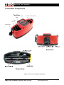
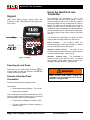
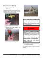
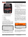
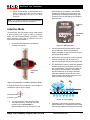
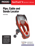
®
NaviTrack 10 Watt
Pipe and Cable Line Transmitter
Operator’s
Manual
CAUTION!
WARNING!
For your own safety, read this
Read this
Operator’s
Manualoperator’s
carefully andmanual
carefully
before
using this
completely before assembling
and tool.
Failure this
to understand
follow
operating
unit. Learn theand
operation,
the contents
of this manual
applications
and potential
hazards tomay
result
this
unit.in electrical shock, fire and/or
serious personal injury.
Table of Contents
GENERAL SAFETY INFORMATION........................................................................................................................ 2
TRANSMITTER COMPONENTS .............................................................................................................................. 5
GETTING STARTED ................................................................................................................................................. 6
INSTALLING/CHANGING BATTERIES ............................................................................................................................ 6
OPERATION TIME ..................................................................................................................................................... 6
OPTIONAL EXTERNAL POWER SOURCE...................................................................................................................... 6
KEYPAD .................................................................................................................................................................... 7
POWERING UP AND DOWN ........................................................................................................................................ 7
SOUNDS OF THE NAVITRACK TRANSMITTER ............................................................................................................... 7
USING THE NAVITRACK LINE TRANSMITTER ..................................................................................................... 7
DIRECT CONNECT METHOD .................................................................................................................................. 8
USEFUL OPERATING POINTS ................................................................................................................................... 10
INDUCTIVE CLAMP METHOD ............................................................................................................................... 10
INDUCTIVE MODE.................................................................................................................................................. 11
FEATURES.............................................................................................................................................................. 12
VARIABLE POWER OUTPUT ..................................................................................................................................... 12
BATTERY LEVEL INDICATOR .................................................................................................................................... 13
AUTO-SHUTDOWN .................................................................................................................................................. 13
25’ COIL CORDS (EXTENDED) ................................................................................................................................. 13
HIGH VOLTAGE INDICATOR...................................................................................................................................... 13
USEFUL INFORMATION ........................................................................................................................................ 14
RESISTANCE AND IMPEDANCE ................................................................................................................................. 14
USING HIGH AND LOW FREQUENCIES ...................................................................................................................... 14
FCC LIMITS ........................................................................................................................................................... 15
TRANSPORTATION AND STORAGE ............................................................................................................................ 15
MAINTENANCE AND CLEANING ................................................................................................................................ 15
LOCATING FAULTY COMPONENTS............................................................................................................................ 15
SERVICE AND REPAIR ............................................................................................................................................. 15
ICON LEGEND ......................................................................................................................................................... 16
ESTIMATED OPERATING TIMES ................................................................................................................................ 16
STANDARD EQUIPMENT .......................................................................................................................................... 16
FCC LIMITS ........................................................................................................................................................... 16
TROUBLE SHOOTING GUIDE ............................................................................................................................... 17
SPECIFICATIONS................................................................................................................................................... 17
ii
www.navitrack.com
Ridge Tool Company
Elyria, Ohio U.S.A
NaviTrack® Line Transmitter
NaviTrack
®
10 Watt Line Transmitter
NaviTrack
®
10W Line Transmitter
Record the Serial Number of your unit below and retain for your records.
See bottom panel for serial number.
Serial
Number
Ridge Tool Company
Elyria, Ohio U.S.A
www.navitrack.com
1
General Safety Information
Battery Precautions
•
WARNING
Read and understand all instructions.
Failure to follow all instructions listed below
may result in electric shock, fire, and/or
serious injury.
•
•
SAVE THESE INSTRUCTIONS!
Work Area Safety
•
•
•
Keep your work area clean and well lit.
Cluttered benches and dark areas may cause
accidents.
Do not operate electrical devices or power
tools in explosive atmospheres, such as in
the presence of flammable liquids, gases, or
heavy dust. Electrical devices or power tools
create sparks which may ignite the dust or
fumes.
Keep bystanders, children, and visitors
away while operating tool. Distractions can
cause you to lose control.
•
•
•
•
2
Do not attach the leads to a high voltage
line.
Do not operate the system with electrical
components removed. Exposure to internal
parts increases the risk of injury.
Avoid exposure to rain or wet conditions.
Keep battery out of direct contact with water.
Water entering electrical devices increases the
risk of electric shock.
Use only in the manner specified. Protection
provided by the equipment may be impaired if
used in a manner not specified by the
manufacturer.
Do not open the transmitter case. High
voltages are present and no serviceable parts
are available.
www.navitrack.com
Recharge batteries with charging units
specified by the battery manufacturer. Using
an improper charger can overheat and rupture
the battery.
Properly dispose of the batteries. Exposure
to high temperatures can cause the battery to
explode, so do not dispose of in a fire. Some
countries have regulations concerning battery
disposal.
Please
follow
all
applicable
regulations.
Personal Safety
•
•
•
Electrical Safety
•
Use only the size and type of battery
specified. Do not mix cell types (e.g. do not
use alkaline with rechargeable). Do not use
partly discharged and fully charged cells
together (e.g. do not mix old and new).
•
•
•
•
Avoid Traffic. Pay close attention to moving
vehicles when using on or near roadways.
Wear visible clothing or reflector vests. Such
precautions may prevent serious injury.
Stay alert, watch what you are doing and
use common sense. Do not use tool while
tired or under the influence of drugs, alcohol, or
medications. A moment of inattention while
operating tools may result in serious personal
injury.
Gloves should always be worn for health
and safety reasons. Sewer lines are
unsanitary and may contain harmful bacteria
and viruses.
Do not overreach. Keep proper footing and
balance at all times. Proper footing and
balance enables better control of the tool in
unexpected situations.
Use safety equipment. Always wear eye
protection. Dust mask, non-skid safety shoes,
hard hat, or hearing protection must be used for
appropriate conditions.
Use proper accessories. Do not place this
product on any unstable cart or surface. The
product may fall causing serious injury to a child
or adult or serious damage to the product.
Prevent object and liquid entry. Never spill
liquid of any kind on the product. Liquid
increases the risk of electrical shock and
damage to the product.
Ridge Tool Company
Elyria, Ohio U.S.A
NaviTrack® Line Transmitter
NaviTrack Line Transmitter Use and Care
•
•
•
•
•
•
•
•
Use equipment only as directed. Do not
operate the NaviTrack Transmitter unless
proper training has been completed and the
owners manual read
Do not immerse the leads or case in water.
Store in a dry place. Such measures reduce
the risk of electric shock and equipment
damage.
Store idle tools out of the reach of children
and other untrained persons. Tools are
dangerous in the hands of untrained users.
Maintain tools with care. Properly maintained
tools are less likely to cause injury.
Check for breakage of parts, and any other
conditions that may affect the NaviTrack’s
operation. If damaged, have the tool serviced
before using. Many accidents are caused by
poorly maintained tools.
Use only accessories that are recommended
by the manufacturer for your tool.
Accessories that may be suitable for one tool
may become hazardous when used on another
tool.
Keep handles dry and clean; free from oil
and grease. Allows for better control of the tool.
Protect against excessive heat. The product
should be situated away from heat sources
such as radiators, heat registers, stoves or
other products (including amplifiers) that
produce heat.
Service
•
•
•
•
Tool service must be performed only by
qualified repair personnel. Service or
maintenance performed by unqualified repair
personnel could result in injury.
When servicing a tool, use only identical
replacement parts. Follow instructions in the
Maintenance Section of this manual. Use of
unauthorized parts or failure to follow
maintenance instructions may create a risk of
electrical shock or injury.
Follow
instructions
for
changing
accessories. Accidents are caused by poorly
maintained tools.
Provide proper cleaning. Remove battery
before cleaning. Do not use liquid cleaners or
aerosol cleaners. Use a damp cloth for
cleaning.
Ridge Tool Company
Elyria, Ohio U.S.A
•
•
Conduct a safety check. Upon completion of
any service or repair of this product, ask the
service technician to perform safety checks to
determine that the product is in proper
operating condition.
Damage to the product that requires service.
Remove the batteries and refer servicing to
qualified service personnel under any of the
following conditions:
o If liquid has been spilled or objects have
fallen into product;
o If product does not operate normally by
following the operating instructions;
o If the product has been dropped or
damaged in any way;
o When the product exhibits a distinct
change in performance.
CAUTION
Remove batteries entirely before shipping.
If you have any questions regarding the service or
repair of this machine, call or write to:
Ridge Tool Company
Technical Service Department
400 Clark Street
Elyria, Ohio 44035-6001
Tel: (800) 519-3456
E-mail: [email protected]
www.ridgid.com
In any correspondence, please give all the
information shown on the nameplate of your tool
including model number and serial number.
WARNING
NaviTrack and SeekTech locators are diagnostic
tools that sense electromagnetic fields emitted by
objects underground. They are meant to aid the
user in locating these objects by recognizing
characteristics of their field lines and displaying
them on the screen. As electromagnetic field lines
can be distorted and interfered with it is important
to verify the location of underground objects
before digging.
Exposing the utility is the only way to verify its
existence, location and depth. Ridge Tool Co.,
its affiliates and suppliers, will not be liable for
any injury or any direct, indirect, incidental or
consequential damages sustained or incurred
by reason of the use of the NaviTrack.
www.navitrack.com
3
DANGER
ALWAYS HOOK UP LEADS FIRST BEFORE
POWERING THE UNIT ON TO AVOID SHOCK.
ALWAYS TURN UNIT OFF BEFORE TOUCHING
AND DISCONNECTING LEADS.
ELECTRIC SHOCK MAY RESULT FROM
FAILURE TO CONNECT LEADS BEFORE
POWERING THE UNIT ON.
DO NOT HANDLE THE TRANSMITTER WHILE
YOU ARE CONNECTED DIRECTLY TO
GROUND YOURSELF.
The line transmitter is normally powered by
internal batteries, and is designed to protect the
user from voltages up to 240 VAC that may be
accidentally encountered. Powering the line
transmitter by batteries provides the highest level
of isolation and safety, and is therefore the
recommended power source.
The line transmitter may also be powered by an
optional external power supply. The user must
ensure that the external power source is fully
isolated from ground and from the power mains.
The user is cautioned to use only external power
sources recommended by the manufacturer. If a
line transmitter is powered by an external source
that is not isolated from ground and from the
power mains, the line transmitter is not protected
from connection to live power lines! The line
transmitter may be destroyed and may present a
safety hazard. DO NOT USE NON-ISOLATED
POWER SUPPLIES WITH THE LINE
TRANSMITTER.
4
www.navitrack.com
DANGER
If the line transmitter is powered by a vehicle 12
VDC cigarette lighter connection, and the line
transmitter is connected to a power line, the
vehicle is now connected to that power line. The
vehicle is now at a potentially lethal voltage. If
the vehicle is grounded, the line transmitter may
be destroyed.
DANGER
Note: Connection To Energized Conductors
The line transmitter is designed to withstand up to
240 VAC 50/60 Hz excitation between the two
leads. The user is cautioned not to deliberately
connect to live power lines. The protection is not
intended to be used continuously. If the transmitter
indicates the presence of high voltage, use high
voltage precautions to carefully disconnect the line
transmitter from the high voltage source.
European Frequency Set
The NaviTrack 10-watt transmitter as delivered in
Europe is slightly different than the version delivered
in U.S. Markets.
European frequencies are limited to 95 KHz. The
version of the NaviTrack transmitter for European
markets has a top frequency of 93 KHz. The U.S.
version has a 262kHz frequency capability. See
instructions on page 9 concerning the use of these
frequencies.
Ridge Tool Company
Elyria, Ohio U.S.A
NaviTrack® Line Transmitter
Transmitter Components
Top View
Handle
Keypad
Coil Cord (25 ft. (8m) extended)
Pocket
Clip
Shoulder Strap
Back View
Bottom View
Figure 1: NaviTrack Transmitter Components
Ridge Tool Company
Elyria, Ohio U.S.A
www.navitrack.com
5
Getting Started
Installing/Changing Batteries
conventional alkaline cells under high demand
applications). Operation at low temperatures will
reduce battery life.Typical operating times will be
generally on the order of those shown here.
To install batteries into the NaviTrack line transmitter,
turn the knob on the battery holder counter clockwise.
The battery carriage will pull out slightly. Pull straight
back on the knob to slide out. Insert the batteries as
shown on the inside decal.
These figures assume
approximately 150 ohms.
Fit the carriage into the case and turn the knob
clockwise while lightly pushing in to close. The
battery carriage can be installed in either orientation.
Current
Est. Time to Depletion
400 mA
1.8 hours
200 mA
3.6 hours
100 mA
7.25 hours
50 mA
14 hours
25 mA
28 hours
a
nominal
load
of
Estimated Operating Times
Batteries can recover after being subjected to high
loads. If time is allowed, batteries may recover
enough to offer additional hours of operation.
Optional External Power Source
Figure 2: Inserting Battery Case
Note: When replacing batteries use 8 D cells that
are the same type. Do not mix Alkaline with NiCad,
for example. Be sure to replace with batteries
where all of the cells have the same amount of
charge. Do not mix half-used cells with new.
Use only a power supply approved to IEC 61010-1 or
IEC 60950. Output must be isolated, SELV and
Limited-Energy Circuit per IEC 61010-1 or LPS per
IEC 60950, 12-15VDC, 30W minimum. Output
connection is standard barrel plug, 2.1mm pin, tip
positive.
DANGER
CAUTION
Always remove batteries before shipping the
unit.
Operation Time
If the line transmitter is powered by a vehicle
12 VDC cigarette lighter connection, and the
line transmitter is connected to a power line,
the vehicle is now connected to that power
line. The vehicle is now at a potentially lethal
voltage. If the vehicle is grounded, the line
transmitter may be destroyed.
Typical operation time for the NaviTrack line
transmitter, when using alkaline cells, is about 12.5
hours depending on factors such as load and current
transmitted. Other factors that affect the operation
time will include chemistry of the battery. (Many of
the new high performance batteries, such as the
“Duracell ® ULTRA”, last 10%-20% longer than
6
www.navitrack.com
Ridge Tool Company
Elyria, Ohio U.S.A
NaviTrack® Line Transmitter
Using the NaviTrack Line
Transmitter
Keypad
LEDs reflect Battery Charge, Output Power, and
Frequency in Use. LED values scale from right to left
(low to high).
The NaviTrack line transmitter is part of the
NaviTrack cable and pipe locating system. It can be
used to energize a pipe or line, so that the magnetic
field lines emitted from the underground line may be
traced. This allows the ground above the line to be
marked so that it can be avoided during a dig, or
exposed for repair or replacement. Underground lines
can be energized with the NaviTrack line transmitter.
This active signal is then traced using a NaviTrack
receiver.
The NaviTrack line transmitter can apply an active
tracing signal to a target conductor in three ways:
Direct Connect – The receiver’s leads are
connected directly to the target conductor or tracing
wire, and a suitable ground. See page 9.
Inductive Clamp (optional) – The jaws of the
inductive clamp encircle the target conductor; there is
no metal-to-metal contact. (See Figure 9).
Figure 3: Keypad
Inductive (internal coils) – The transmitter is
placed over and in-line with the utility . Its internal
coils generate a field which induces current in the
underground target conductor. (See page 10).
Powering Up and Down
Power the unit on by depressing the Power
key
on the keypad. To power the unit down, depress and
release the Power key again.
Sounds of the NaviTrack
Transmitter
WARNING
Always connect leads before turning the
transmitter on to avoid electrical shock. Ensure
transmitter is well grounded.
Sounds are associated with specific events.
They include:
•
Ascending/Descending Beeps – Turn On/Off.
•
Beeps upon connection.
The unit will beep, then pause to measure how much
current is flowing onto the cable or pipe. The unit will
beep faster when more current is detected.
•
Double-beep on shifting into inductive mode.
•
Four-tone intermittent trill when operating in
inductive mode.
Ridge Tool Company
Elyria, Ohio U.S.A
www.navitrack.com
7
Direct Connect Method
1. Attach the NaviTrack transmitter
to the line.
Remove the ground spike from the bottom of the unit
and insert it into the ground. Connect one of the
transmitter’s leads to the grounding spike.
Figure 6: Alternative Connection to a Pipeline
Note: To increase safety it is recommended
that the ground lead be attached first. If there
was any high voltage running through the target
line then providing a ground would allow a means
of redirecting this current away from the transmitter
and operator. These are universal leads so either
may be used for the ground.
Figure 4: Attaching Lead to Ground Stake
2. Connect the other lead to the
target conductor.
DANGER
NEVER CONNECT TO LINES ENERGIZED WITH
A POTENTIALLY DANGEROUS ELECTRICAL
CURRENT. To increase safety, the ground lead
should be attached first. If there were an unknown
high voltage running through the target line, this
would allow a means of redirecting the current
away from the transmitter and operator.
ALWAYS HOOK UP LEADS FIRST BEFORE
POWERING THE UNIT ON TO AVOID SHOCK.
ALWAYS
TURN
UNIT
DISCONNECTING LEADS.
OFF
BEFORE
Figure 5: Example of Connecting to a Line
Power the transmitter on by pressing the Power key.
3. Select a Frequency
This is done by pressing the key for the desired
frequency.
8
www.navitrack.com
Ridge Tool Company
Elyria, Ohio U.S.A
NaviTrack® Line Transmitter
current on the line. More current means a stronger
signal will be received by the receiver.
To prolong battery life and reduce the chance of the
signal “bleeding over” onto adjacent lines, use the
minimum amount of current needed to get a clear
reading on the receiver.
5. Adjust Current.
Figure 7: Frequency Selection
The power output for the chosen frequency can be
modified in five increments from low to high. Once
you have chosen a frequency, press the same
frequency button a second time. The LED
corresponding to the current power level will flash..
While it is flashing choose a power level by pressing
one of the frequency buttons. (Lower power settings
start on the left, higher toward the righ). When you
press one of the frequency buttons during the period
when the original light is flashing it will set the power
level. The beep rate will increase or decrease as
power is increased or decreased. (See “Variable
Output Power” on page 12.)
There are 6 frequencies to choose from.
•
•
•
•
•
•
128Hz Low
1kHz Low
8kHz Medium
33kHz Medium
262kHz (93kHz Europe) High
200 kHz Alternate High Frequency
A 200 KHz frequency is available. It is set by
pressing on the 262Hz High Frequency button for ten
seconds. The transmitter will blink three LEDs rapidly
when the frequency is set. The LED over the 262 kHz
label will blink once every 5 seconds to indicate the
transmitter is on the alternate frequency of 200 kHz
rather than the labeled frequency of 262 kHz.
Note: The high frequency on European models is
93 kHz. The 200 kHz button on European models
will set the transmitter to 93,623 Hz. A long press
(greater than one second) on the same button will
set the transmitter to 93,696 Hz., to accommodate
older receivers which may be tuned to this variant
of 93 kHz.
4. Check the Circuit
More current gives a stronger signal. Less current
prolongs battery life. Signal strength measured by the
receiver is directly proportional to the amount of
Ridge Tool Company
Elyria, Ohio U.S.A
The approximate current levels of the power settings
are 4 mA,15 mA,50 mA,150 mA, and 600 mA. Actual
power output varies with circuit conditions
(resistance, impedance and quality of connections).
When a current level is chosen, the transmitter will
adjust the voltage to try and produce the selected
current and lock it in. If the transmitter cannot
produce the current selected it will adjust down to the
next level.
The transmitter’s maximum current and power output
depend on the circuit.
WARNING
If the transmitter is reporting low or no current (low
beep rate), the signal may be too low to be
detected by the receiver locator and inadequate for
tracing.
6. Check the Receiver
Confirm that your receiver is set to the same
frequency as the NaviTrack transmitter. Confirm the
receiver is picking up the transmitted frequency by
holding it near the transmitter and observing the
increase in receiver signal.
www.navitrack.com
9
•
Increasing the output power generally improves
the locate if there is a good circuit.
Note: increased output reduces the battery levels
faster.
DANGER
Figure 8: Checking the Signal
Useful Operating Points
• The lower the total resistance, the more current
will be put on the line. A good circuit is one that
allows enough current to flow so that the locator
gets a clear and stable signal.
•
•
•
•
•
10
ALWAYS HOOK UP LEADS FIRST BEFORE
POWERING THE UNIT ON TO AVOID SHOCK.
ALWAYS POWER UNIT OFF BEFORE
DISCONNECTING LEADS.
Inductive Clamp Method
To help lower the resistance of the circuit,
scrape away dirt, paint and corrosion before
connecting to the target conductor or grounding
spike.
A good ground lowers resistance, which allows
more current flow and a stronger signal. For a
better connection to ground, insert the
grounding spike as far as possible. Moist
ground is a better conductor than dry soil.
Wetting the ground can improve a circuit in dry
soil.
Lower frequencies travel farther and produce
less “bleed over” to other conductors. Higher
frequencies have the benefit of “jumping”
gaps/breaks in tracer wires or pipes but do not
travel as far. High frequencies can complicate
the locate by “coupling” onto other conductors.
If the condition of the conductor is unknown, try
lower frequencies first.
The transmitter’s leads can act as antennas,
broadcasting a strong signal. If locating close to
the transmitter, keep the leads as short as
possible by stowing the excess length in the
transmitter’s side pockets. This will reduce the
amount of interfering signals from the leads.
It is usually best to start by using the lowest
frequency and the least amount of current
needed to effectively illuminate the line. Lower
frequencies travel farther. Higher frequencies
generally make it easier to illuminate a line, but
they do not travel as far and are much more
likely to couple onto other utility lines. This can
distort the signal and reduce accuracy.
www.navitrack.com
Figure 9: Inductive Clamp (Optional)
Using the optional Inductive Clamp allows you to
induce a traceable current onto a pipe or cable where
direct-connect with lead clips is not feasible.
Separately grounding the transmitter is not necessary
using the Inductive Clamp. But note that the line into
which current is induced must be grounded in both
directions for a signal to be induced away from the
transmitter.
1. Plug the inductive clamp into the 1/4" phone
jack above the battery cover. Plug must be
mono or, if stereo, connected between tip
and base. The coil cords are disabled when
the clamp is connected.
2. Clamp the jaws of the Inductive Clamp
around a section of the pipe or cable to be
traced.
Ridge Tool Company
Elyria, Ohio U.S.A
NaviTrack® Line Transmitter
3. Power the transmitter on and proceed as in
Direct Connect mode. Be sure the receiver
and the transmitter are set to the same
frequency.
LED will light up (in addition to the selected
frequency) to let the user know that the line
transmitter is transmitting inductively on that
frequency.The tone will change from single to
grouped tones.
Note: The Inductive Clamp is not recommended
for use at frequencies less than 8 kilohertz.
Induction
LED
Inductive Mode
The NaviTrack 10W Transmitter can be used without
a direct connection to a pipe or cable. In Inductive
Mode, the NaviTrack-transmitter generates a field
which induces a current into a conductor such as a
pipe running directly beneath it.
1. Be sure that the transmitter is positioned
correctly over the line.
Orientation
Guide
Figure 11: Induction LED
3. Lower frequencies (less than 8kHz) couple
poorly inductively. When using Inductive
Mode, use higher frequencies in order to get a
good signal at the receiver.
4. Note that the line into which current is induced
must be grounded in both directions for a
signal to be induced away from the transmitter.
Orientation
Mark
5. The transmitter in inductive mode will generate
a field through the air around it as well as into
the ground under it. If the receiver is within 30
feet (10m) of the transmitter it will measure
this field instead of on the target conductor.
Place the transmitter at least 30 feet (10m)
away from the region where tracing occurs in
order to avoid this “air coupling”.
Figure 10: Orientation to Conductor (Inductive Mode)
A slight tilt relative to the conductor’s axis is helpful in
reducing the chance of air-coupling:
Transmitter
Conductor
Figure 12: Air-Coupling
2. To use a frequency in the inductive mode
select the frequency. Then push the same
frequency key a second time for
approximately 2 seconds. The inductive red
Ridge Tool Company
Elyria, Ohio U.S.A
6. Generally if you trace a line with an induced
signal checking for a valid depth measurement
and a strong stable proximity signal is the best
www.navitrack.com
11
way to confirm that you are locating the
induced signal in a line and not the signal
directly from the transmitter through the air (air
coupling).
Note: If you have been using the NaviTrack
transmitter in inductive mode, be certain to switch
inductive mode off if you are going to use the unit in
direct connect mode. Air coupling can create very
confusing signals if you inadvertently have the unit
set to inductive mode but are trying to use it in
direct connect mode.
Figure 14: Flashing LED Indicates Medium Power
Level
3. The original frequency LED will then come
back on constantly. (See the FCC limitation in
the specifications section for information on
frequencies and power output.)
Features
Variable Power Output
The power output can be adjusted to apply more
current to a line. Higher currents are easier to trace
as they create more signal for the receiver to track
but they also use the battery power faster.
1. Turn the unit on and press one of the
frequency buttons to select a frequency to use.
The LED representing that frequency will shine
steadily.
Figure 15: Steady 1kHz LED
Figure 13: Selecting a 1 kHz Frequency
2. Press the same frequency key quickly and
release. One of five levels of output will be
shown by a flashing LED. The lowest is the
farthest to the left. Note the bar graph above
the LEDs for reference.
12
www.navitrack.com
Note: When the LED is constant it is showing the
frequency selected.
When it is flashing it
represents the power level. If the frequency
selected corresponds to the same level of output,
the same LED will flash and then return to a
steady light.
Selecting another LED while the LED is steady will
change the frequency To change the power output
select another level while the LED is flashing. The
new power level will flash five times, and the LED will
then appear steadily over the chosen frequency. The
beep frequency will rise accordingly if you have
increased the power. If you check the power output
again by pressing the currrent frequency rapidly, the
new power-selection will be indicated by the LED
over it flashing rapidly.
Ridge Tool Company
Elyria, Ohio U.S.A
NaviTrack® Line Transmitter
Shutdown is being enabled, and will run down (right
to left) when the Auto-Shutdown feature is being
disabled.
25’ Coil Cords (Extended)
Specially designed, hybrid copper and stainless steel
aircraft-grade coiled cables allow the leads to be
stretched out to offer more freedom in choosing
grounding points and connections to the line.
Figure 16: Output Power Scale
Note: To avoid tangled cords, “feed” the cords
back into the pockets, clip going last, when storing.
(Output increases from left (low) to right (high)
Power maximum is 10 Watts at frequency settings
below 45 kHz, and 1 Watt at frequencies greater than
45 kHz, due to FCC regulations.
Like this:
Not like this
Battery Level Indicator
The battery levels can be checked as well. With the
unit on, hold down the Power ON/OFF key until all of
the LEDs light up; then release it. The LEDs will
begin to flash after a moment. The number of LEDs
flashing, from left to right, corresponds to the battery
level. Refer to the bar graph above the LEDs. For
example, 2 flashing LEDs indicate a lower battery
level than 4 flashing LEDs
Figure 18: Correct Storage of Coil Cords
High Voltage Indicator
Whenever the line transmitter encounters voltage
higher than about 90V (peak) it will flash a red LED at
the bottom left of the keypad. If this occurs, follow
high-voltage safety procedures to disconnect the
transmitter. Do not connect the transmitter to a live
power line.
Figure 17: Checking Battery Level
Battery Level proceeds from left (low) to right (high).
Auto-Shutdown
By default, the NaviTrack 10W transmitter will shut
itself down if no key is pressed in four hours (at low
power levels). At high power, the shutdown will occur
in about 1 hour. Auto-shutdown can be toggled on or
off by very rapidly double-pressing the power switch.
The LED lights will run up (right to left) when Auto-
Ridge Tool Company
Elyria, Ohio U.S.A
Figure 19: High Voltage Warning LED
www.navitrack.com
13
WARNING
Connect leads before powering the transmitter
on to avoid electrical shock. Ensure the transmitter is well grounded.
known as the frequency of the generated current and
of its consequent magnetic field.
Frequency is expressed in terms of hertz (Hz), which
means cycles per second, or kilohertz (kHz), which
means thousands of cycles per second.
Low Frequencies
Useful Information
Resistance and Impedance
A circuit has a certain resistance that is measured in
ohms (Ω). Higher resistance reduces the amount of
current that can be put on an underground line at a
given voltage. (Current is equal to voltage divided by
resistance). Factors that affect resistance are
conductivity of the line itself, insulation material and
condition, breaks or faults in the line, and how well
the transmitter is grounded.
Grounding can be affected by soil conditions
(wetness or dryness, for example), length of
grounding stake, or how the line transmitter is
connected to the grounding rod. Improving the
ground connection is the quickest way to improve a
tracing circuit.
Note: It is difficult to set up a good ground connection
in extremely dry soil. This condition can be remedied
by moistening the soil around the grounding stake.
Impedance is resistance which varies with AC
frequency. The measurement units in both cases are
the same, ohms. Impedance increases with the
frequency transmitted. Total “resistance” can include
impedance, and can be effected by inductance and
capacitance in the circuit and nearby metallic objects.
Using High and Low Frequencies
Understanding the behaviour of different frequencies
under different conditions can be important in doing
effective and accurate locates.
In both direct-connect and inductive mode, the
NaviTrack transmitter is essentially doing the same
thing – imposing a wave of traceable energy onto the
target pipe or line. This electrical energy rises and
falls a certain number of times per second, which in
turn causes a magnetic field to build and collapse
around the conductor at a regular rate. This rate is
14
www.navitrack.com
The NaviTrack transmitter will generate frequencies
as low as 128 hertz. Low frequencies are especially
useful for several reasons. First, they will travel
farther at a detectable level along a continuous pipe
or wire conductor than a high frequency will.
Secondly, lower frequency fields lose less energy to
the area around the conductor. If you can get a clear
signal on your receiver using a low frequency, it is
generally preferable because you will be able to trace
it further and it will tend to confine itself to the original
conductor more than a high-frequency signal will. But
a low-frequency signal is more likely to be interrupted
by gaps in the line, poor insulation or hidden by other
magnetic fields in the area. It is a “weaker” signal in
that respect. While it doesn’t jump as readily onto
other lines, it will lose signal if traveling on a line with
poor insulation, bare-concentric cable, or bare pipe
exposed to earth, and will follow the path of least
resistance, which is not always the path intended by
the operator. This can make tracing the original
conductor difficult.
High Frequencies
The NaviTrack transmitter will generate frequencies
as high as 262 kilohertz. There are certain conditions
where only higher frequencies will serve. Highfrequency signals are especially valuable when you
are tracing a line that has some sort of interruption—
such as a gasket, or decayed insulation – in the
continuity of the conductor. The reason is that a highfrequency signal can “jump” some barriers and
continue without losing as much signal.
A high-frequency signal can also be valuable in
getting a signal on a receiver when there is a poorly
grounded circuit, compared to the signal the same
receiver will detect at a lower frequency. While all
currents tend to follow the path of least resistance, a
high-frequency current will “buck” this tendency to
some degree, reaching across incidental barriers.
The disadvantage to higher frequencies is that they
also jump onto other conductors (known as bleedover). If you have two wires side by side in a trench,
a higher frequency used to trace one of them may
Ridge Tool Company
Elyria, Ohio U.S.A
NaviTrack® Line Transmitter
illuminate both of them. Additionally, nearby metallic
objects, or even highly metalized soil, may pick up a
higher frequency and distort the picture at the locator.
If a gas line is being “illuminated” with a high
frequency current, it may bleed over onto a water line
or a power cable running nearby, confusing the
picture of where the original line is.
As a general rule, detecting with lower frequencies is
more reliable for the reasons given above, IF you can
get a good signal.
Maintenance and Cleaning
1. Keep the NaviTrack line transmitter clean with
a damp cloth and some mild detergent. Do not
immerse in water.
2. When cleaning, do not use scraping tools or
abrasives as they may permanently scratch
the display. NEVER USE SOLVENTS to clean
any part of the system. Substances like
acetone and other harsh chemicals can cause
cracking of the case.
High Frequencies:
Locating Faulty Components
•
Don’t travel as far
•
Overcome some barriers
•
Bleed-over more.
For troubleshooting suggestions, please refer to the
trouble shooting guide at the end of the manual. If
necessary, contact SeekTech Technical Service at
(800) 519-3456. We will establish a plan of action to
get your equipment working for you.
Low Frequencies:
Service and Repair
•
Travel further
•
Lose signal when hitting barriers, gaskets,
poor insulation
•
Do not bleed-over as much.
FCC Limits
47 CFR 15.213 says that from 9kHz up to (but not
including) 45kHz, peak output power shall not exceed
10 W. From 45kHz to 490kHz, it must not exceed
1W.
Transportation and Storage
Before transporting make sure that the unit is OFF to
preserve battery power.
Transmitter should be taken to a RIDGID
Independent Authorized Service Center or returned
to the factory.
All repairs made by Ridge service facilities are
warranted against defects in material and
workmanship.
If you have any questions regarding the service or
repair of this machine, call or write to:
Ridge Tool Company
Technical Service Department
400 Clark Street
Elyria, Ohio 44035-6001
Tel: (800) 519-3456
E-mail: [email protected]
Make sure that the NaviTrack line transmitter is
secure and does not bounce around or get bumped
by loose equipment.
For the name and address of your nearest
Independent Authorized Service Center, contact the
Ridge Tool Company at (800) 519-3456 or
www.ridgid.com.
The NaviTrack line transmitter should be stored in a
cool dry place.
CAUTION
Note: If storing the NaviTrack line transmitter for
an extended period of time, the batteries should be
removed. If storage is brief then the battery
carriage may be pulled out ½ an inch to preserve
battery power. Remove batteries entirely before
shipping.
Ridge Tool Company
Elyria, Ohio U.S.A
Always remove
shipping.
batteries
www.navitrack.com
entirely
before
15
Icon Legend
Estimated Operating Times
Current
Est. Time to Depletion
400 mA
1.8 hours
200 mA
3.6 hours
100 mA
7.25 hours
50 mA
14 hours
25 ma
28 hours
Standard Equipment
•
•
•
•
NaviTrack Line Transmitter
Direct connect leads and clips
Operator’s Manual
8 D-cell batteries (Alkaline)
FCC Limits
47 CFR 15.213 says that from 9kHz up to (but not
including) 45kHz, peak output power shall not exceed
10 W. From 45kHz to 490kHz, it must not exceed
1W.
16
www.navitrack.com
Ridge Tool Company
Elyria, Ohio U.S.A
NaviTrack® Line Transmitter
Trouble Shooting Guide
PROBLEM
PROBABLE FAULT LOCATION
Check that the correct frequency is selected, and that the transmitter is the correct
mode (direct-connect/inductive).
Make sure that the leads to line and to the ground are attached securely
Receiver will not pick
up the line transmitter’s signal.
Too much resistance impeding current flow. Improve ground connection by deepening
stake, moistening ground, or relocating stake. Improve circuit by relocating transmitter
on line.
Increase power output.
European Models: If using 93 kHz setting, try using the alternative 93 kHz frequency.
See page 9 for instructions on the use of these frequencies.
Check orientation of batteries.
Check that the batteries are charged.
Check to see that the battery contacts are OK.
Unit will not power on.
Specifications
Standard Replacement Parts
Power Source:
8 Alkaline or rechargeable batteries.(D-Cells)
Weight:
4.75 lbs (2.15 kg) w/o batteries
7.5 lbs (3.4 kg) w/batteries
Cable Length:
25’ (8m)extended
~3 feet (1m) contracted
Dimensions:
Depth ..................... 7.0” (17.7 cm)
Width ..................... 15” (38.1 cm)
Height .................... 6.5” (16.5 cm)
Output Power:
Nominal 10 watts maximum if under 45kHz,
1 watt maximum if frequency is above 45kHz.
Power Settings:
4 mA
15 mA
50 mA
150 mA
600 mA
A. Direct Connect Lead (25’ (8m) (Cat # 18423)
B. Battery Holder Cover Assembly (Cat # 18428)
C. Battery Holder (Cat # 18433)
D. Ground Spike (Cat # 18438)
E. Direct Connect Lead Clip (Cat # 18443)
F. (Optional) Inductive Clamp (Cat # 20503)
Ridge Tool Company
Elyria, Ohio U.S.A
www.navitrack.com
17
What is covered
RIDGID® tools are warranted to be free of defects in workmanship and material.
How long coverage lasts
This warranty lasts for the lifetime of the RIDGID® tool. Warranty coverage ends when the product becomes unusable
for reasons other than defects in workmanship or material.
How you can get service
To obtain the benefit of this warranty, deliver via prepaid transportation the complete product to RIDGE TOOL
COMPANY, Elyria, Ohio, or any authorized RIDGID® INDEPENDENT SERVICE CENTER. Pipe wrenches and other
hand tools should be returned to the place of purchase.
What we will do to correct problems
Warranted products will be repaired or replaced, at RIDGE TOOL’S option, and returned at no charge; or, if after three
attempts to repair or replace during the warranty period the product is still defective, you can elect to receive a full
refund of your purchase price.
What is not covered
Failures due to misuse, abuse or normal wear and tear are not covered by this warranty. RIDGE TOOL shall not be
responsible for any incidental or consequential damages.
How local law relates to the warranty
Some states do not allow the exclusion or limitation of incidental or consequential damages, so the above limitation or
exclusion may not apply to you. This warranty gives you specific rights, and you may also have other rights, which
vary, from state to state, province to province, or country to country.
No other express warranty applies
This FULL LIFETIME WARRANTY is the sole and exclusive warranty for RIDGID® products. No employee, agent,
dealer, or other person is authorized to alter this warranty or make any other warranty on behalf of the RIDGE TOOL
COMPANY.
Ridge Tool Company
400 Clark Street
Elyria, Ohio 44036-2023
Part Number :
748-010-604-0A-P3
Rev. B
Printed in U.S.A. 3/98