1
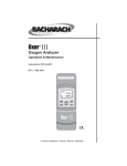
Monoxor III ® Carbon Monoxide Analyzer Instruction 19-9326 Operation & Maintenance Rev. 2 – October 2003 Product Leadership • Training • Service • Reliability Notice: • •• • • • •••• • • •• •• ••• • • • •• •• • • •• • • • • • • • •••••••• •• • •••• •••••••••••• •••• •• ••••• •• •• •• •• •••• • •• •• •• ••• • •• • • • •••••••••• • • • • •• • ••• •• ••• • • •• • ••• • • • ••••• •• ••••••••••••••••••••••••• • • • •- • tained in this document may change without notice. Bacharach, Inc. shall not be liable for errors contained herein or for incidental or consequential damages in connection with the furnishing, performance, or use of this material. No part of this document may be photocopied, reproduced, or translated to another language without the prior written consent of Bacharach, Inc. Copyright © 2002–2003, Bacharach, Inc., all rights reserved. BACHARACH and Monoxor are registered trademarks of Bacharach, Inc. All other trademarks, trade names, service marks and logos referenced herein belong to their respective companies. A Instruction 19-9326 Monoxor III Contents 1.0 INTRODUCTION...................................................................................1 2.0 TECHNICAL CHARACTERISTICS...................................................3 3.0 PREPARING THE ANALYZER FOR OPERATION........................5 3.1 Battery Installation..........................................................................5 3.2 Probe Installation.............................................................................6 3.3 Front Panel Pushbuttons..................................................................7 3.4 Setup Mode........................................................................................8 3.4.1 Entering Setup.......................................................................8 3.4.2 Temperature Units Setup......................................................8 3.4.3 CO Channel Zero Setup.........................................................9 3.4.4 Time Setup............................................................................10 3.4.5 Date Setup............................................................................10 3.4.6 Year Setup............................................................................11 3.4.7 Selecting Printer Protocol....................................................11 3.4.8 Exiting the Setup Screen.....................................................11 4.0 OPERATION.........................................................................................13 4.1 Taking a Gas Sample......................................................................13 4.2 Ending a Test..................................................................................14 4.3 Turning OFF the Analyzer.............................................................14 4.4 CO Purge During Turn OFF..........................................................14 4.5 CO Sensor Error Screen.................................................................15 4.6 Using the Backlight........................................................................15 4.7 Using the Probe...............................................................................15 4.8 Operating Tips................................................................................16 4.9 Resetting the Microprocessor.........................................................16 4.10 Printing Test Results....................................................................17 5.0 CALIBRATION & MAINTENANCE.................................................19 5.1 Entering the Calibration Mode and Testing the Display Segments....19 5.2 Ambient Temperature Calibration................................................ 20 5.3 CO Sensor Zero & Calibration........................................................20 5.4 Water Trap / Filter Maintenance...................................................22 5.5 CO Sensor Replacement.................................................................23 5.6 Pump Assembly Replacement........................................................24 6.0 PARTS & SERVICE.............................................................................27 6.1 Replacement Parts..........................................................................27 6.2 Accessories.......................................................................................27 6.3 Service Centers...............................................................................28 7.0 HAZARDS OF CARBON MONOXIDE..............................................29 Instruction 19-9326 Monoxor III Notes ii Instruction 19-9326 Monoxor III 1.0 INTRODUCTION The Monoxor III is a portable analyzer designed to detect and display concentrations of Carbon Monoxide (CO) gas between 0 and 2000 ppm. The analyzer is capable of testing for CO in both ambient room air, and in the flue-gas stream of fossil-fuel fired furnaces and boilers. Ordering Information: Part No. Description 19-8104 Monoxor III, includes 4 ‘AA’ batteries, probe & hose assembly with integral water-trap / filter, and a hard carrying case 19-8105 Monoxor III, includes 4 ‘AA’ batteries, probe & hose assembly with integral water-trap / filter, hard carrying case, plus an IrDA printer with an assortment of printer accessories including an AC adapter, roll of paper, in-car charger, belt clip, and magnet The analyzer detects and displays the presence of CO by first drawing in a gas sample from the area being tested by the analyzer’s built-in motorized pump. The gas sample is next directed into a sensor chamber where the sample is analyzed for the presence of CO. If CO is detected, the CO ppm level is displayed on the analyzer’s LCD. A permanent record of the detected CO level, along with the current time and date, can be made by using the optional wireless IrDA printer. A backlight enables the operator to read the display in dimly-lit areas. A power-saver feature causes the backlight to automatically turn OFF after 10 minutes, and causes the analyzer to shut OFF after 20 minutes of inactivity. The power saver feature, however, is disabled while the detected CO level is above 50 ppm. When the analyzer is used to measure the CO content in flue-gas, a rigid stainless steel probe with handle is provided that allows gas samples to be taken from within the flue stack. An integral water-trap / filter prevents water and soot from being drawn into the analyzer. The probe can also be used in ambient testing to draw in gas samples from cramped and confined areas. If the analyzer is turned OFF while a high level of CO is still present within the unit, the analyzer’s pump remains running and the unit will not turn OFF until the detected CO level drops below 50 ppm. Instruction 19-9326 Monoxor III Notes Instruction 19-9326 Monoxor III 2.0 TECHNICAL CHARACTERISTICS CO Display Range....................... 0–2000 ppm Accuracy...................................... ±5% of reading or ±10 ppm, whichever is greater* Resolution.................................... 1 ppm Response Time............................ 90% of final value within 40 sec. Battery Requirement.................. Four disposable ‘AA’ Alkaline batteries Operating Time........................... Up to 18 hours continuous (pump running and backlight off) Warm Up Time............................ 10 or 60 seconds (depending on CO channel zero setup, refer to Page 9) Display......................................... 4 digit by 2 line, 7-segment Liquid Crystal Display Front Panel Controls................... Six push button switches (refer to Section 3.3) Operating Temperature: Analyzer.................................. 32–104 °F (0–40 °C) Probe........................................ 1000 °F (538 °C) max. at 5" insertion Humidity...................................... 15 to 90% RH (non-condensing) Printer Port................................. IrDA or HP protocol Weight.......................................... 16 oz with batteries Size............................................... 7.5"H x 3.1"W x 2.1"D (190x79x53 mm) * Tighter accuracy in the lower ranges, up to ±2 ppm, may be attained if a lower range calibration gas (e.g. 100 ppm CO) is used. Instruction 19-9326 Monoxor III Notes Instruction 19-9326 Monoxor III 3.0 PREPARING THE ANALYZER FOR OPERATION To prepare a new analyzer for operation, you must install four ‘AA’ A lkaline batteries, install the probe (if needed), and set the correct time and date as described in the following paragraphs. For your convenience, and to ensure that the analyzer will provide reliable CO readings, the CO sensor was installed and the analyzer calibrated on 500 ppm CO at the factory. 3.1 Battery Installation Install fresh batteries as described below. Check the analyzer for sufficient charge prior to each use. Replace the batteries if the low-battery symbol appears in the lower right corner of the LCD. To install batteries: 1. Remove battery cover from back of unit (see Figure 3-1). 2. If old batteries are installed, remove and properly dispose of the batteries. 3. Observing the polarity markings inside the battery compartment, install four ‘AA’ Alkaline batteries. 4. Replace battery cover. � � � � � � �� � ��� �� �� � � � ��� � � � � � �� � �� � � � �� � �� � � � � � � � �� ��� �� � ����� � �� � � � � �������� � �������� � �������� � �������� Figure 3-1. Battery Installation Instruction 19-9326 Monoxor III 3.2 Probe Installation Install the probe if the analyzer is going to be used for flue-gas CO measurements, or if gas measurements need to be taken from a cramped or confined area. To install the probe, simply slide its hose over the GAS inlet of the analyzer (see Figure 3-2). � � � � �� � � � � � � � � � � � �� � � � �� � �� � � � �� � � � � � � � Figure 3-2. Probe Connection Instruction 19-9326 Monoxor III 3.3 Front Panel Pushbuttons Note that a push button may perform several functions, depending on what screen is being displayed at the time. I/O •Turns analyzer ON/OFF. There is a 10 or 60 second warmup and a 5 second turn-off-delay period. •Places the analyzer into either its Setup or Calibration Mode when used in conjunction with the ENTER or HOLD button. •Bypasses the CO purge function during turn-off. •Causes the displayed value to increase or change while in the Calibration or Setup Mode. •Causes the displayed value to decrease or change while in the Calibration or Setup Mode. ENTER •Starts a test – pump ON. •Sets up the analyzer to be placed into its Calibration Mode when held down with the analyzer OFF. (Used in conjunction with the I/O button.) •Stores the displayed value and automatically steps to the next screen when pressed during calibration or setup. •Displays the CO screen when held down for 2 seconds while in the Calibration Mode. •Aborts turn-off and keeps the analyzer turned ON when pressed during either the 5 second turn-off-delay period, or the CO purge cycle. HOLD LIGHT •Freezes the display and stops the pump during a test. •Starts a printout when pressed twice with the pump running, or when pressed once with the pump OFF. •Sets up the analyzer to be placed into its Setup Mode when held down with the analyzer OFF. (Used in conjunction with the I/O button.) Toggles the backlight ON and OFF. Instruction 19-9326 Monoxor III 3.4 Setup Mode The analyzer is preset at the factory for the parameters shown below, but can be changed as described in their associated sections. Function Parameter To Change Temperature Unit °F Section 3.4.2 CO Channel Auto Zero Section 3.4.3 Time Not Set Section 3.4.4 Date Not Set Section 3.4.5 Year Not Set Section 3.4.6 Printer IrDA Section 3.4.7 3.4.1 Entering Setup 1. With the analyzer turned OFF, press and hold down the HOLD button. 2. Press and release the I/O button. 3. Release the HOLD button. 4. The analyzer is now in its Setup Mode. Refer to Sections 3.4.2 thru 3.4.7 for information on how to set the analyzer’s various parameters. 3.4.2 Temperature Units Setup The Temperature Units Setup Screen is labeled “Unit”. Note: The analyzer uses an internal temperature sensor to maintain CO sensor accuracy under varying ambient temperature conditions. This sensor’s temperature reading is displayed only during calibration as described in Section 5.2. Instruction 19-9326 Monoxor III 1. Enter the Setup Mode per Section 3.4.1. If necessary, repeatedly press ENTER until the Temperature Units Setup Screen is displayed. 2. Press the or button until the desired temperature unit (°F or °C) is displayed. 3. Press ENTER to move to the next Setup Screen, or I/O to exit setup. 3.4.3 CO Channel Zero Setup The CO Channel Setup Screen is labeled “CO”. 1. Enter the Setup Mode per Section 3.4.1. If necessary, repeatedly press ENTER until the CO Channel Setup Screen is displayed. 2. Press the or button until the desired parameter is displayed. - no Sensor disabled. Note that when the CO sensor is disabled the CO measurement screen will display “Err” instead of the current CO level. - 2Ero Manual Zero – Warm-up time is 10 seconds, and the analyzer does not zero the CO sensor to ambient conditions during this period. For example, if the atmosphere contains 25 ppm CO at start up, the analyzer will immediately display 25 ppm. The zero point, however, can be manually adjusted by performing Steps 1–4 of Section 5.3. - A2 Auto Zero – Warm-up time is 60 seconds, and the CO sensor is zeroed to the ambient CO level during this period. For example, if the atmosphere contains 25 ppm CO at start up, the analyzer will display 0 ppm. It’s very important that when in this mode the analyzer be turned ON in fresh air; otherwise, incorrect CO readings will occur. 3. Press ENTER to move to the next Setup Screen, or I/O to exit setup. Instruction 19-9326 Monoxor III 3.4.4 Time Setup There are two Time Setup Screens, one for hours and the other for minutes. Two bars appear above the segments being changed. The clock is in a 24 hour format, but will appear as AM/PM on the printout. � 1. Enter the Setup Mode per Section 3.4.1. If necessary, repeatedly press ENTER until the first Time Setup Screen is displayed—the one with two bars over the hour digits. 2. Press the or button until the correct hour value is displayed. 3. Press ENTER to move the selection bars over the minute digits. 4. Press the or button until the correct minute value is displayed. 5. Press ENTER to move to the next Setup Screen, or I/O to exit setup. 3.4.5 Date Setup There are two Date Setup Screens, each labeled “DAtE”. The first screen sets the month while the second screen sets the day. � � � � � �� � 1. Enter the Setup Mode per Section 3.4.1. If necessary, repeatedly press ENTER until the first Date Setup Screen is displayed. 2. Press the or button until the correct month is displayed. 3. Press ENTER to switch to the second Date Setup Screen. 4. Press the or key until the correct day is displayed. 5. Press ENTER to move to the next Setup Screen, or I/O to exit setup. 10 Instruction 19-9326 Monoxor III 3.4.6 Year Setup The Year Setup Screen is labeled “yEAr”. � � 1. Enter the Setup Mode per Section 3.4.1. If necessary, repeatedly press ENTER until the Year Setup Screen is displayed. 2. Press the or button until the correct year is displayed. 3. Press ENTER to move to the next Setup Screen, or I/O to exit setup. 3.4.7 Selecting Printer Protocol The Printer Setup Screen is labeled “Prnt”. The analyzer can be set up to send data to a wireless printer using either HP or IrDA protocol. 1. Enter the Setup Mode per Section 3.4.1. If necessary, repeatedly press ENTER until the Printer Setup Screen is displayed. 2. Press the or button to select the desired protocol. 3. Press ENTER to move to the next Setup Screen, or I/O to exit setup. 3.4.8 Exiting the Setup Screen Press the I/O button at any time to exit the Setup Mode and turn the analyzer OFF. Note that the last displayed parameter is automatically saved in memory. Instruction 19-9326 11 Monoxor III Notes 12 Instruction 19-9326 Monoxor III 4.0 OPERATION To operate the Monoxor III, you simply . . . •Turn the analyzer ON •Wait for the unit to warm up •Take a gas sample 4.1 Taking a Gas Sample Important! If the CO channel is set up for Auto Zero (refer to Section 3.4.3), ensure that the analyzer will be sampling fresh air (containing no CO) when turned ON. Turn ON the analyzer by pressing the I/O button. Observe that when power is first applied, the software revision level is first displayed followed by a screen that counts down the warm-up period. The warm-up period is either 60 seconds (Auto Zero Mode) or 10 seconds (Manual Zero Mode). � Following warm-up, the CO screen appears. This screen shows the current detected CO level in ppm. If the probe is being used, insert the probe tip into the area to be sampled. � � � � � Note: If a sensor error was detected during warm-up, the CO Sensor Error Screen will be displayed. Refer to Section 4.5. Front Panel Button Functions: – No effect – No effect HOLD – Freezes display and stops pump; pressing a second time activates printing ENTER – Restarts testing after the HOLD button was pressed LIGHT – Toggles backlight ON/OFF I/O – Turns analyzer OFF (with a 5 second delay) Instruction 19-9326 13 Monoxor III 4.2 Ending a Test WARNING! Burn Hazard. Do not touch the probe after removing it from a flue. Allow the probe to cool before handling (about 5 minutes). After taking a gas sample, remove the probe and take the analyzer to an area containing fresh air. Allow the pump to run until the CO reading drops to near zero. 4.3 Turning OFF the Analyzer Turn OFF the analyzer by pressing the I/O button. The analyzer will count down from 5 before turning OFF. Pressing ENTER, however, will abort the count down and keep the analyzer ON. Note: The analyzer will automatically turn itself OFF after 20 minutes of keyboard inactivity, unless the detected CO level is above 50 ppm. 4.4 CO Purge During Turn OFF If the detected CO level is above 50 ppm when the analyzer is turned OFF, the unit will remain ON with its pump running and display “PUrG CO”. The countdown from 5 will not begin until the CO level drops below 50 ppm. Pressing ENTER during CO purge will return the analyzer to the CO measurement screen. Although not recommended for routine use, the CO purging process can be bypassed by pressing the I/O button a second time, which will immediately turn OFF the analyzer. 14 Instruction 19-9326 Monoxor III 4.5 CO Sensor Error Screen When the CO channel is set up for Auto Zero (refer to Section 3.4.3), a CO sensor error will occur if the detected Carbon Monoxide level is above 50 ppm during the warm-up period. Note, however, that if the CO channel is set up for manual calibration, the analyzer does not auto-zero the CO sensor during warm-up, and thus does not generate a CO sensor error when the analyzer is turned ON in an atmosphere containing a high background level of CO. Make the following checks before replacing a suspected spent or defective sensor: 1. Turn OFF the analyzer and turn it back ON in an area of fresh air. 2. If Step 1 doesn’t eliminate the error condition, replace the sensor per Section 5.5. 4.6 Using the Backlight The LCD can be read in dimly-lit areas by pressing the LIGHT button. The backlight automatically turns OFF after 10 minutes of keyboard inactivity, but can be turned OFF at any time by again pressing the LIGHT button. 4.7 Using the Probe A rigid stainless steel probe with handle, connected to a flexible hose with integral water-trap / filter can be used to draw a gas sample into the analyzer from the room, grilles, diffusers, and furnace flues. The hose and probe assembly can be detached from the analyzer when the operator desires to sample without the probe. Instruction 19-9326 15 Monoxor III 4.8 Operating Tips •When an analyzer is brought in from a cold vehicle, let it warm up slowly to minimize condensation. Temperatures below freezing will not damage the analyzer; however, bringing a cold analyzer into a warm, humid environment may cause condensate to form inside the case. •If the CO channel is set up for Auto Zero (refer to Section 3.4.3), ensure that the analyzer is sampling fresh air when turned ON. Pulling a flue-gas sample through the analyzer during its warm-up period will not damage the analyzer, but it will result in incorrect CO readings. Also note that a CO sensor error will occur if the detected CO level is above 50 ppm during warm-up. •Flue-gas condensate is acidic and very corrosive. It is important not to allow the analyzer’s internal components to become soaked in condensate for long periods of time. •Before each use, inspect the filter element of the water-trap / filter assembly. Replace the filter if it looks dirty. •During a test, keep the analyzer above the water-trap, and keep the trap in a vertical position. This will maximize the effectiveness of the trap and keep liquid condensate from being drawn directly into the analyzer. •When liquid condensate is seen inside the water trap, empty the trap before it becomes full. Refer to Section 5.4. •It is recommended that the analyzer be purged after taking a flue-gas measurement before turning it OFF. Once the probe is removed from the stack, disconnect the hose assembly from the bottom of the analyzer and let the pump run for 10 minutes or so to completely remove any remaining flue gases, and dry any condensate from inside the sensor chamber. •When storing the analyzer, it’s a good idea to empty the water trap and leave it open to further dry it out. •Calibrate the analyzer about every 6 months to ensure its accuracy. 4.9 Resetting the Microprocessor If the analyzer ‘locks up’ and cannot be turned OFF, reset the microprocessor by removing one of the batteries for 5 seconds. 16 Instruction 19-9326 Monoxor III 4.10 Printing Test Results Turn ON the printer. Refer to the printer’s instruction manual for detailed operation and maintenance information. If not already done, set the printer parameters as follows: • Data – 8 bits • Baud – 9600 • Parity – None • Handshaking – X-on/X-off Align the printer with the top of the analyzer as shown in Figure 4-1. Begin printing by doing one of the following: - If the pump is running, press the HOLD button twice. � � � � � � � � � �� � �� � ��� �� � � � � - If the display has been previously frozen, press the HOLD button only once. Tip: If the printer does not operate correctly, ensure that the correct printer protocol has been selected per Section 3.4.7. � � � � � � � � � � � � � � � � � � � � � � � � � � � � � � � � � � � � � � � � � � � � � � � � � � � � � � � � � � � � � � � � � � � � � � � � � � � � � � � � � � � � � � � � � � � � � � � � � � � � � � � � � � � � � � � � � � � � � � � � � � � � � � � � Figure 4-1. Printer Alignment & Sample Printout Instruction 19-9326 17 Monoxor III Notes 18 Instruction 19-9326 Monoxor III 5.0 CALIBRATION & MAINTENANCE Important: Fresh batteries should be installed, and the unit allowed to stabilize at room temperature for at least two hours before proceeding with calibration. To maintain accuracy as listed in the Technical Characteristics Section of this manual, the standards used must be at least 4 times as accurate as the stated accuracy of the Monoxor III. 5.1 Entering the Calibration Mode and Testing the Display Segments 1. With the analyzer turned OFF, place the unit in fresh, ambient air; then press and hold down the ENTER button. 2. Press the I/O button and release it. Observe that all LCD segments are turned ON. 3. Release the ENTER button. Observe the unit’s model number and software version are displayed. The word “CAL” is then displayed while the unit counts down from either 10 or 60 seconds. Note that the count-down time is dependent on whether the CO channel is set up for manual or automatic zero – refer to Page 9. � At the end of the count-down period, the first calibration screen is automatically displayed. Note: During calibration, the and buttons are used to increase or decrease a displayed calibration value. ENTER is used to store the new value and move to the next screen. Exit the Calibration Mode by holding down the ENTER button for 2 seconds. Instruction 19-9326 19 Monoxor III 5.2 Ambient Temperature Calibration Material Required: Calibrated Thermometer Procedure: 1. Enter the Calibrate Mode as described in Section 5.1. Observe that “AMBIENT” is displayed at the top of the display; if not, repeatedly press ENTER until it appears. 2. Use the and buttons to adjust the displayed value to match the reading of a calibrated thermometer. 3. Press ENTER to store the displayed value and move to the next calibration screen, or hold down ENTER for 2 seconds to store the displayed value and display the CO screen, or press the I/O button to exit the Calibration Mode and turn OFF the analyzer without saving the changes. 5.3 CO Sensor Zero & Calibration Material Required: •Cylinder of 100 ppm (P/N 51-1994) or 500 ppm (P/N 24-0492) CO calibration gas • Calibration Kit, P/N 24-7059 If you are primarily performing flue-gas testing, calibrate the Monoxor III with 500 ppm CO calibration gas. If the analyzer will be primarily used for ambient testing, then you may wish to consider 100 ppm CO calibration gas. Procedure: 1. With the analyzer sampling fresh air, enter the Calibration Mode as described in Section 5.1. Then repeatedly press the ENTER button until “CO” appears in the upper left side of the display. 20 Instruction 19-9326 Monoxor III 2. Allow the pump to run and sample fresh air for at least 1 minute. 3. Use the and buttons to set the displayed value to 0 ppm. 4. Do one of the following: a. End this procedure and save the new zero value by holding down the ENTER button for 2 seconds; after which, the CO screen is displayed. b. Continue with Step 5 to span the CO sensor to a known concentration of carbon monoxide. 5. Set up the Calibration Kit with 100 or 500 ppm CO as described in the instructions supplied with the kit. 6. Connect the tubing of the Calibration Kit to the inlet of the analyzer; then adjust the regulator for approximately 2 SCFH of excess flow (see Figure 5.1). 7. After the analyzer has stabilized (2 to 3 minutes), use the and buttons to set the displayed value to match the CO concentration stamped on the gas cylinder. 8. Press ENTER to store the new calibration values and move to the next calibration screen, or hold down ENTER for 2 seconds to store the new calibration values and display the CO screen, or press the I/O button to exit the Calibration Mode and turn OFF the analyzer without saving the changes. 9. Disconnect tubing from analyzer and turn off gas flow. � � � � � �� � � � � � � �� � � � � � � � � � � � ��� �� � � � � � � ��� � ��� � ��� � ��� � ��� � ��� � �� � � � �� � ��� � � � � � � �� �� � � � � �� � � � � � �� � � � �� � � ����� � ��� � � � �� �� � � ��� �� � ��� � � ��� � �� �� � Figure 5-1. Calibration Kit Hookup Instruction 19-9326 21 Monoxor III 5.4 Water Trap / Filter Maintenance The Water Trap / Filter Assembly removes water condensate from the gas sample, and also prevents soot from contaminating the internal components of the analyzer. Drain the water condensate after every test. Procedure: 1. Pull apart the Water Trap / Filter assembly (see Figure 5-2). 2. Pour out all water condensate; then reassemble the trap. Replace the Filter Element when dirty. Material Required: Filter Element, P/N 07-1644 Procedure: 1. Pull apart the Water Trap / Filter assembly (see Figure 5-2). 2. Pry apart the Filter Chamber; then remove and discard old filter. 3. Install new filter and reassemble trap, making sure that surfaces “A” and “B” are in contact. � � ���� � � � ��� � �� � �� �� ��� � �� �� �� ��� � �� � ��� � � � � � � �� � � � � � � � � � � � �� � � � � � � � � � � � � � �� � � � ������� � �� � � � � � � �� � �� � � �� � � ������ �� � �� � � �� � � � � � � �� � � � �� � � � �� � ��� �� �� � �� � � �� � � � �� � � � � � � �� � � � �� � �� � �� � � � ��� � � � ���� � ��� � ��� � ��� � � �� � � ��� �� � � � � ��� � � � �� � �� � ��� ��� � � � � �� � �� �� � Figure 5-2. Water Trap / Filter Assembly 22 Instruction 19-9326 Monoxor III 5.5 CO Sensor Replacement Material Required: Procedure: • CO Sensor, P/N 24-7265 • CO Sensor Gasket, P/N 24-1112 • #1 Phillips Screwdriver 1. Disassemble the analyzer as follows: a. Remove the battery cover and the batteries, uncovering one of the cover hold-down screws. b. Remove and set aside all four cover hold-down screws. c. With the analyzer on its back, remove the front cover, laying it face down to the left of the body. d. Carefully remove the circuit board, slipping off the battery connector on top, and then laying the circuit board face down in the top cover. 2. Gently pull CO sensor out of its socket (see Figure 5-3). 3. Properly dispose of the old CO sensor (see the instruction sheet that comes with the new sensor). 4. It is recommended that the CO sensor gasket (see Figure 5-4) be replaced at the same time as the sensor. Remove the old gasket and discard. Remove the paper backing from the new gasket and adhere it to the case in the same position as the old one. 5. Insert the new CO sensor into its socket. 6. Reassemble the analyzer. Instruction 19-9326 23 Monoxor III 5.6 Pump Assembly Replacement Material Required: • Pump, P/N 24-3020 • #1 Phillips Screwdriver Procedure: 1. Disassemble the analyzer as follows: a. Remove the battery cover and the batteries, uncovering one of the cover hold-down screws. b. Remove and set aside all four cover hold-down screws. c. With the analyzer on its back, remove the front cover, laying it face down to the left of the body. d. Carefully remove the circuit board, slipping off the battery connector on top, and then laying the circuit board face down in the top cover. 2. Slip off the pump motor’s electrical connector from the circuit board. 3. Unscrew the pump’s hold down clamp and remove it from the pump (see Figure 5-4). Make note of how the pump wiring is routed. 4. Make note of how the tubing connects to the pump; then carefully remove tubing from pump. 5. Remove the old pump and discard. 6. Install the new pump and reinstall the tubing, taking care not to pinch or crimp the tubing. Also be sure that the pump wiring is routed as was noted in Step 3. 7. Reassemble the analyzer. 24 Instruction 19-9326 Monoxor III � � � � � � � � � �� � � � �� � � � � � � � � � � � � ��� � � � � � �� � � � �� � � � � � � Figure 5-3. CO Sensor Located on Backside of Printed Circuit Board Instruction 19-9326 25 Monoxor III Figure 5-4. Back Case Component Locations 26 Instruction 19-9326 Monoxor III 6.0 PARTS & SERVICE 6.1 Replacement Parts Description Part No. Carbon Monoxide Sensor......................................................................24-7265 Carbon Monoxide Sensor Gasket.......................................................... 24-1112 Pump Assembly.................................................................................... 24-3020 Water Trap / Filter Assembly, Complete..............................................19-3265 Water Trap / Filter Assembly, Filter Element (pack of 3)................... 07-1644 6.2 Accessories TANDARD ACCESSORIES: S Battery, ‘AA’ Alkaline (Qty 4)............................................................ 204-0004 Instruction Manual...............................................................................19-9326 Probe, Hose, and Water Trap / Filter Assembly.................................. 19-7110 Quick Start Guide.................................................................................19-9327 Hard Carrying Case............................................................................ 24-0865 OPTIONAL ACCESSORIES: AC Adapter (Battery Eliminator).........................................................24-1254 Calibration Kit......................................................................................24-7059 Gas Cylinder, 100 ppm CO................................................................... 51-1994 Gas Cylinder, 500 ppm CO.................................................................. 24-0492 Soft Carrying Case...............................................................................24-1267 Printer, Wireless IrDA w/120 VAC Charger (part of kit 19-8105)......24-1229 Printer Paper: 1 Roll.............................................................................................. 06-8733 5 Roll Pack...................................................................................... 24-1310 Protective Rubber Boot w/Magnet.......................................................24-1127 True Spot Smoke Test Set.................................................................... 21-7006 Filter Paper, True Spot (40 strips)..................................................21-0019 Instruction 19-9326 27 Monoxor III 6.3 Service Centers Replacement parts and service can be obtained by contacting one of the following Bacharach Service Centers: United States México California 7281 Garden Grove Blvd., Suite H Garden Grove, CA 92841 Phone: 714-895-0050 Fax: 714-895-7950 Email: [email protected] Bacharach de México Playa Regatas No. 473 Tercer Piso Col. Militar Marte Delegación Iztacalco, 08830 México D.F. México Phones: +52-555-634-7740 +52-555-634-7741 FAX: +52-555-634-7738 Email: [email protected] New Jersey 7300 Industrial Park Rte. 130, Bldg. 22 Pennsauken, NJ 08110 Phone: 856-665-6176 Fax: 856-665-6661 Email: [email protected] Pennsylvania 621 Hunt Valley Circle New Kensington, PA 15068 Phone: 724-334-5051 Fax: 724-334-5723 Email: [email protected] Canada Bacharach of Canada, Inc. 250 Shields Court Unit #3 Markham, Ontario L3R 9W7 Canada Phone: 905-470-8985 Fax: 905-470-8963 Email: [email protected] 28 Europe European Headquarters Bacharach Instruments Sovereign House, Queensway Royal Leamington Spa Warwickshire CV31 3JR United Kingdom Phone: +44-1926-338111 Fax: +44-1926-338110 Email: [email protected] Sales / Service Center - Denmark Bacharach Instruments Int'l P.O. Box 44 39 Lindegade DK 6070 Christiansfeld Denmark Phone: +45-74-563171 Fax: +45-74-563178 Email: [email protected] Instruction 19-9326 Monoxor III 7.0 HAZARDS OF CARBON MONOXIDE Carbon Monoxide (CO) poisoning results in headache, nausea, chronic tiredness, confusion, dizziness, and sometimes coma or death. CO effects people by cutting off the supply or Oxygen to their muscles and brain. The harmful effects of CO exposure depend on both the concentration of CO in the air and the length of exposure. Concentration of CO in Air Inhalation Time and Toxic Symptoms Developed 50 ppm* (0.005%) Maximum allowable concentration for continuous exposure in any 8‑hour period. 200 ppm* (0.02%) Slight headache, tiredness, dizziness, nausea after 2–3 hours. 400 ppm (0.04%) Frontal headaches within 1–2 hours, life threatening after 3 hours. 800 ppm (0.08%) Dizziness, nausea and convulsions within 45 minutes. Unconsciousness within 2 hours. Death within 2–3 hours. 1,600 ppm (0.16%) Headache, dizziness and nausea within 20 minutes. Death within 1 hour. 3,200 ppm (0.32%) Headache, dizziness and nausea within 5–10 minutes. Death within 30 minutes. 6,400 ppm (0.64%) Headache, dizziness and nausea within 1–2 minutes. Death within 10–15 minutes. 12,800 ppm (1.28%) Death within 1–3 minutes. For additional information on CO and its dangers, ask your sales representative about Bacharach’s Institute of Technical Training CO Seminars. * Maximum CO concentration for exposure at any time as prescribed by OSHA. Effects can vary significantly based on age, sex, weight, and overall state of health. Instruction 19-9326 29 Monoxor III Notes 30 Instruction 19-9326 Monoxor III Notes Instruction 19-9326 31 Printed in U.S.A.