1
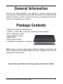
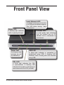
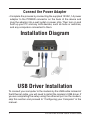
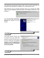
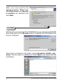
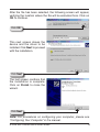
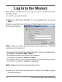
General Information
The D-Link DSL-2320B is an ADSL2+ modem offering the
convenience of both Ethernet and USB connections. This Quick Install
Guide provides you with a simple and easy-to-understand format to
install and configure your modem.
Package Contents
• ADSL2/2+ Ethernet/USB Modem
• 12VDC, 1A DC CEC-compliant switching power adapter
• RJ-11 telephone cable
• RJ-45 Ethernet cable
• USB Cable
• Quick Install Guide
• CD-ROM (User Manual + Drivers)
Note: Using a power supply with a different voltage rating than the
one included with the DSL-2320B will cause damage and void the
warranty for this product.
If any of the above items are missing, please contact your reseller.
D-Link DSL-2320B Quick Install Guide
Important Safety Instructions
•Place your modem on a flat surface close to the cables in a location
with sufficient ventilation.
•To prevent overheating, do not obstruct the ventilation openings of
this equipment.
•Plug this equipment into a surge protector to reduce the risk of
damage from power surges and lightning strikes.
•Operate this equipment only from an electrical outlet with the correct
power source as indicated on the adapter.
•Do not open the cover of this equipment. Opening the cover will void
any warranties on the equipment.
•Unplug equipment first before cleaning. A damp cloth can be used
to clean the equipment. Do not use liquid/aerosol cleaners or
magnetic/static cleaning devices.
D-Link DSL-2320B Quick Install Guide
Front Panel View
Local Network LED
Status LED
A solid light indicates a connection
to an Ethernet-enabled computer.
This LED blinks during data
transmission.
Internet LED
A blinking light indicates
traffic is passing through.
Power LED
A solid green light
indicates the unit
is powered up.
A solid green light indicates
that the modem has an IP
address and is connected to
the internet.
USB LED
A Solid light indicates a connection is
established using USB. A flashing LED
indicates traffic is being sent and received
using USB.
DSL LED
A Solid light indicates the DSL
is synchronized. A flashing LED
indicates the modem is attempting to
synchronize with the DSL provider.
D-Link DSL-2320B Quick Install Guide
Rear Panel View
LAN Port
Connect Ethernet devices
such as computers, switches,
and hubs.
ON/OFF
Press this button to
turn the unit on or off.
Power Receptor
Receptor for the supplied
power adapter.
DSL Line
Connect to an active
telephone line (RJ-11).
Reset
Pressing the Reset button
restores the modem to its original
factory default settings.
USB Port
Connect a computer
using a USB cable.
D-Link DSL-2320B Quick Install Guide
Installing the Modem
Connect the ADSL and Telephone Lines
•Connect an RJ-11 cable between the wall phone jack and the lineend of the splitter (see diagram below).
•Attach another RJ-11 phone cable to the modem-end of the splitter
and the ADSL port on the rear panel of the modem.
•The phone-end of the splitter will be connected to the telephone
using a third RJ-11 phone cable.
Note: See connections on the installation diagram.
Connect the PC to the Modem
•To use the Ethernet connection, connect the Ethernet cable from the
computer directly to the modem. Connect one end of the Ethernet
cable to the port labeled LAN on the back of the modem and attach
the other end to the Ethernet port of your computer.
•Or, you can use the supplied USB cable to connect your computer
directly to the modem. Connect one end of the USB cable to the
USB port on the back of the modem and connect the other end to
a free USB port on your PC. The Found New Hardware Wizard will
open on your PC. See Installation Diagram on page 7.
•If your LAN has more than one computer, you can attach one end of
an Ethernet cable to a hub or a switch and the other to the Ethernet
port (labeled LAN) on the modem. Note that either a crossover
or straight-through Ethernet cable can be used. The modem
automatically recognizes the type of connection that is required.
D-Link DSL-2320B Quick Install Guide
Connect the Power Adapter
•Complete the process by connecting the supplied 12VAC, 1A power
adapter to the POWER connector on the back of the device and
plug the adapter into a wall outlet or power strip. Then turn on and
boot up your PC and any LAN devices, such as hubs or switches,
and any computers connected to them.
Installation Diagram
USB Driver Installation
To connect your computer to the modem by the USB cable instead of
the Ethernet cable, you will need to install the modem’s USB driver. If
you are completing the setup using the ethernet port on the modem,
skip this section and proceed to “Configuring your Computer” in the
manual.
D-Link DSL-2320B Quick Install Guide
The following are general steps (may vary for each computer) to
complete the USB driver installation on a Windows® 2000.
The following pop-up window appears when you connect the USB
cable to your computer (with the other end already attached to the
modem).
The Found New Hardware
Wizard will appear on your
screen.
Click Next
The next screen allows you
to select how you want the
wizard to search for the driver
on your computer. The default
selection is set to search for a
suitable driver for my device
(recommended).
Click Next
D-Link DSL-2320B Quick Install Guide
Next, you can specify the
search locations. Make sure
CD-ROM drives and Specify
a Location are selected and
click Next.
Click Next
At this point, you can insert the CD-ROM into your computer’s CD-ROM
drive and click on the Browse button to specify the CD-ROM drive
of your computer.
The driver is located in the folder named Bcm63xx_WHQL_usb_
driver. The file name is usbdslur.inf. Click Open to proceed with the
installation.
D-Link DSL-2320B Quick Install Guide
After the file has been selected, the following screen will appear,
verifying the location where the file will be extracted from. Click on
OK to continue.
Click OK
This next screen shows the
device and the driver to be
installed. Click Next to proceed
with the installation.
Click Next
The last screen confirms that
the installation is complete.
Click on Finish to close the
wizard.
Click Next
Note: For procedures on configuring your computer, please see
“Configuring Your Computer” in the manual.
D-Link DSL-2320B Quick Install Guide
10
Log in to the Modem
This section will explain how to log in to your modem using the
following steps:
1.Launch your web browser.
2.Enter the URL http://192.168.1.1 in the address bar and press
Enter.
A login screen like the one below will be displayed after you connect
to the user interface.
Note: There are three account types, each requiring a different
username and password.
•The user account provides limited access to certain configurations
(username / password: user / user).
•The admin account can perform all functions
(username / password: admin / admin).
•The support account is for ISP technicians for maintenance purposes
(username / password: support / support).
Note: Passwords can be changed at any time.
3. Enter your user name and password, and then click OK to display
the user interface.
11
D-Link DSL-2320B Quick Install Guide
Technical Support
D-Link’s website contains the latest user documentation and
software updates for D-Link products.
U.S. and Canadian customers can contact D-Link Technical
Support through our website or by phone.
United States
Telephone
(877) 453-5465
World Wide Web
http://support.dlink.com
Canada
Telephone
(800) 361-5265
World Wide Web
http://support.dlink.ca
Version 1.0
Revised 09/26/2006
Copyright ©2006 D-Link Corporation/D-Link Systems, Inc. All rights reserved. D-Link and the D-Link logo are registered
trademarks of D-Link Corporation or its subsidiaries in the United States and other countries. Other trademarks are the property
of their respective owners. Network conditions and environmental factors, including volume of network traffic, building materials
and construction, and network overhead lower actual data throughput rate. Product specifications, size and shape are subject
to change without notice, and actual product appearance may differ from that depicted on the packaging. Visit www.dlink.com
for more details.
D-Link DSL-2320B Quick Install Guide
12