1
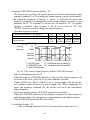
4H358D0180009
Installation Manual
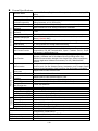
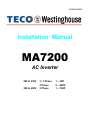
MA7200
AC Inverter
208 to 230V
380 to 460V
1 / 3 Phase
3 Phase
3 Phase
1 ~ 3HP
5 ~ 40HP
1 ~ 75HP
SAFE OPERATION NOTES
Read this instruction manual thoroughly before installation, operation, maintenance
or inspection of the inverter. Only authorized personnel should be permitted to perform
maintenance, inspections or parts replacement.
In this manual, notes for safe operation are classified as:
“WARNING” or “CAUTION”.
WARNING :
Indicates a potentially hazardous situation that, if not avoided,
could result in death or serious injury to personnel.
:
Indicates a potentially hazardous situation that, if not avoided,
may result in minor or moderate injury to personnel and damage
to the equipment.
CAUTION
“WARNING” and “CAUTION”
WARNING
y Always turn off the input power supply before wiring terminals.
y After turning OFF the main circuit power supply, do not touch the circuit
components until the “CHARGE” LED is extinguished.
y Never connect power circuit output U/T1, V/T2, W/T3 to AC power supply.
CAUTION
y When mounting the MA7200 in a separate enclosure, install a fan or other cooling
device to keep the intake air temperature below 113oF (45oC).
y Do not perform a withstand voltage test to the inverter.
y All the parameters of the inverter have been preset at the factory. Do not change
the settings unnecessarily.
This inverter has been placed through demanding tests at the factory before shipment.
After unpacking, check for the following:
1. Verify that part numbers on shipping carton and unit match the purchase order
sheet and/or packing list.
2. Do not install or operate any inverter that is damaged or missing parts.
3. Do not install or operate any inverter that has no QC marking.
Contact your local TECO authorized distributor or TECO representative if any of
the above irregularities have been found.
Contents
Page
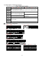
1. MA7200 Handling Description ------------------------------------- 1-1
1.1 Inspection Procedure upon Receiving ---------------------------------------- 1-1
1.2 Installation ------------------------------------------------------------------------ 1-2
1.3 Removing/Attaching of LCD Digital Operator and Front Cover---------- 1-4
1.4 Wiring between Inverter and Peripheral Devices --------------------------- 1-7
1.5 Description of Terminal Function -------------------------------------------- 1-11
1.6 Main Circuit Wiring Diagram -------------------------------------------------1-13
1.7 Wiring Main Circuit------------------------------------------------------------ 1-14
1.8 Inverter Specifications --------------------------------------------------------- 1-17
1.9 Dimensions ---------------------------------------------------------------------- 1-19
1.10 Peripheral Units ----------------------------------------------------------------- 1-22
2. Using LCD Digital Operator----------------------------------------- 2-1
3. Parameter Setting------------------------------------------------------ 3-1
3.1
3.2
3.3
3.4
3.5
Frequency Command An----------------------------------------------- 3-1
-------------- 3-2
Parameters That Can be Changed during Running Bn------------------------------------------------- 3-12
Control Parameters Cn-------------------------------------------------- 3-30
System Parameters Sn--------------------------------------------- 3-75
Monitoring Parameters Un-
4. Fault Display and Troubleshooting ------------------------------ 4-1
4.1 General ---------------------------------------------------------------------------- 4-1
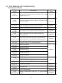
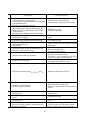
4.2 Error Message and Troubleshooting ------------------------------------------ 4-2
Appendix
A.
B.
C.
D.
E.
F.
G.
H.
I.
J.
K.
PID Parameter Setting ------------------------------------------------------- App-1
Supplementary on PID Control Block Diagram -------------------------- App-3
Wiring for PG Feedback Use------------------------------------------------ App-4
RS-485 Communication Interface ------------------------------------------ App-5
SINK/SOURCE Typical Connection Diagram --------------------------- App-7
RS-232C Serial Communication Connection Diagram------------------ App-8
Set-up Using the Sensorless Vector Control ------------------------------ App-9
Notes for Circuit Protection and Environmental Ratings-------------- App-11
Spare Parts ------------------------------------------------------------------- App-15
Electrical Ratings For Contstant Torque and Quadratic Torque------ App-25
Inverter Heat Loss ---------------------------------------------------------- App-26
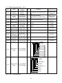
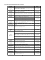
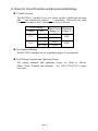
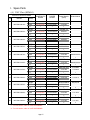
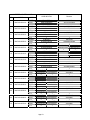
No.
Figure Contents
1 Air clearance for MA7200 wall mounting
2 Standard connection diagram
3 Processing the ends of twisted-pair cables
The optical-couplers connect to external
4
inductive load
5 MA7200 ground winding
6 LCD digital operator dimension
7 Analog operator
8 LCD digital operator
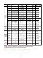
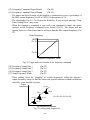
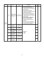
9 Acceleration and Deceleration time
10 Analog input gain and bias
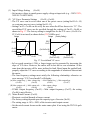
Adjust the auto torque boost gain Bn-11 to
11
increase the output torque
12 Block diagram for PID control in inverter
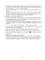
Response of PID control for step-shape
13
(deviation) input
PID Control Block diagram (After Version
14
30.18)
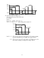
15 An operation example of timer function
16 Time chart for energy-saving operation
17 User-defined V/F curve
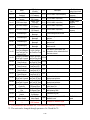
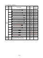
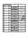
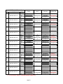
Page No.
Figure Contents
1-2
27 S curve
1-9
28 ASR Integral Gain 2
1-15
29 Deceleration to stop
Page
3-27
3-28
3-44
1-15
30 Coast to Stop
3-44
1-16
1-27
1-28
2-1
3-4
3-5
31
32
33
34
35
36
3-44
3-45
3-48
3-48
3-49
3-51
3-5
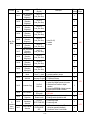
37 3-wire mode connection diagram
3-53
3-7
38 Operation sequence in 3-wire mode
3-53
3-8
39 2-wire mode connection diagram
3-53
3-9
40
3-9
3-10
3-15
41
42
43
18 Output frequency with slip compensation.
3-16
44
19 Slip compensation limit
3-16
45
20 DC injection braking time chart
3-17
46
3-18
47 PID control block diagram
App-3
3-18
3-20
3-20
3-23
3-25
48
49
50
51
52
App-3
App-4
App-5
App-6
App-8
21
22
23
24
25
26
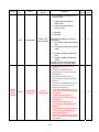
Upper and lower bounds of the frequency
command
Setting jump frequencies
Acceleration stall prevention function
Run stall prevention function
Time chart for overtorque detection
Speed search timing chart
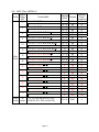
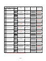
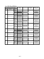
No.
1
2
3
4
5
6
7
8
9
10
11
12
13
14
15
16
Whole range DC Injecting Braking Stop
Coast to Stop with Timer
Output voltage limit
Stall prevention function during deceleration
Zero speed braking operation selection
Motor overload protection curve
Time chart for multi-step speed and jog
command
Acceleration and deceleration ramp hold
Time chart for DC injection braking command
PG speed control block diagram
Time chart of output frequency with the
UP/DOWN function
Pulse signal output
The input/output signal in ‘Timer’ function
application
3-54
3-55
3-57
3-58
3-59
3-65
3-66
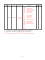
PID wiring diagram
Wiring of PG feedback
Wiring for MODBUS Protocol communication
Wiring for PROFIBUS protocol communication
RS232-C Typical Connection Diagram
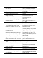
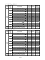
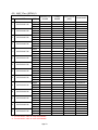
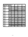
Table Contents
Main circuit terminals
Control circuit terminals
230V/460V class applicable wire size and connector
Brake resistor list
AC reactor list
Noise filter on the input side
Key's functions
Setting of monitoring contents
LCD Digital Operator Display Unit
230V Class Inverter Capacity Selection
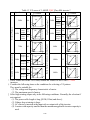
460V Class Inverter Capacity Selection
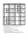
V/F curve of 1~2 HP compact size, 230V Class MA inverter
V/F curve of 3~20 HP, 230V Class MA inverter
Multi-Function Input Setting
Multi-function analog input function list
Multi-function output terminal function
Page
1-11
1-12
1-14
1-22
1-23
1-24
2-2
3-6
3-21
3-39
3-40
3-41
3-42
3-52
3-60
3-63
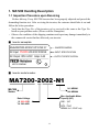
1. MA7200 Handling Description
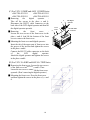
1.1 Inspection Procedure upon Receiving
Before delivery, Every MA7200 inverter has been properly adjusted and passed the
demanding function test. After receiving the inverter, the customer should take it out and
follow the below procedure:
• Verify that the Type No. of the inverter you’ve received is the same as the Type No.
listed on your purchase order. (Please read the Nameplate)
• Observe the condition of the shipping container and report any damage immediately to
the commercial carrier that has delivered your inverter.
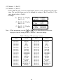
■ Inverter nameplate:
Model:MA7200-2002-N1 HP:2 KVA:2.7
INVERTER MODEL
AC Input: 1PH/3PH 200-230V 50/60Hz
INPUT SPECIFICATION
AC Output: 3PH 0-230V Amps: 6.4A
OUTPUT SPECIFICATION
MOTOR COMPANY
LISTED
(IND. CONT. EQ.)
848F
■ Inverter model number :
MA7200-2002 -N1
N1: NEMA1
N4: NEMA4
MA7200
Series
Max. Applicable Motor
Capacity (HP)
Rated Voltage
2: 200~230V
4: 380~460V
0001 : 1HP
∫ ∫
0075 : 75HP
NEMA4 for 1~20HP only
1-1
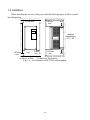
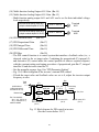
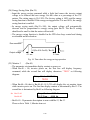
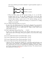
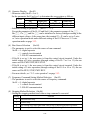
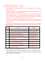
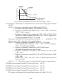
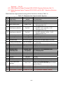
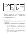
1.2 Installation
When installing the inverter, always provide the following space to allow normal
heat dissipation.
50 mm min.
120 mm
min.
AIR
ambient
temperature
-10 ~ + 40 ℃
50 mm
min.
30 mm
min.
120 mm
min.
30 mm
min.
AIR
(a) Space in Side
(b) Space in Top/bottom
Fig. 1-a. Air clearance for MA7200 wall mounting
1-2
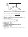
L1(L) L2(N) L3
220-240V
380-480V
Single/ThreePhases
L1(L) L2(N) L3
220-240V
380-480V
Single/ThreePhases
T1 T2 T3
3Phases IM
T1 T2 T3
3Phases IM
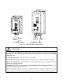
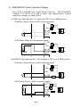
(a) NEMA4 Frame1
(b) NEMA4 Frame2
Fig. 1-b. MA7200 NEMA4 Installation
CAUTION
Location of equipment is important to achieve proper performance and normal
operating life. The MA7200 inverter should be installed in area where the following
conditions exist.
y Ambient temperature: +14 to 104oF, (-10 to 40oC).
y Install the MA7200 in a location protected from rain, moisture and direct sunlight.
y Install the MA7200 in a location free from harmful mists, gases, liquids, airborne
dusts and metallic particles.
y Install the MA7200 in a location free from vibration and electromagnetic noise. (i.e.
welding machines, power units, etc…)
y When mounting multiple units in a common enclosure, install a cooling fan or some
other means to cool the air entering the inverter to at least 113oF (+45oC) or below.
1-3
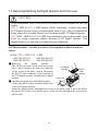
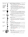
1.3 Removing/Attaching the Digital Operator and Front cover
CAUTION
Please disassemble Front Cover before you connect wires to terminals on MA7200
models.
• 230V 1~25HP & 460V 1~30HP models: Plastic instructions, so please disconnect
LCD Digital Operator before you disassemble Front Cover. After you finished the
wiring connection, assemble Front Cover first then reinstall LCD Digital Operator.
• 230V 30HP、40HP & 460V 40~75HP: Iron instructions, you can disassemble Front
Cover for wiring connection without disconnect LCD Digital Operator. Then
reinstall Front Cover back after you finished wiring connection.
MA7200 disassembly / Assembly procedures will be depended on different model as
follows:
(A) For 230V : 1-2HP, 460V : 1-2HP
y MA7200-2001-N1
y MA7200-4001-N1
y MA7200-2002-N1
y MA7200-4002-N1
d
■ Removing
the
digital
operator
:
c
Take off the two screws on the front cover in the
LCD Digital
place a and b. Remove the front cover and take
Operator
RS-232
off the screws in the place c and d. Disconnect
Cable
Connector
the RS-232 cable connector on the backside of
the LCD digital operator. Lift and remove digital
Front Cover
operator.
■ Attaching the front cover and digital operator:
a
Connect the RS-232 cable connector on the back
b
of the LCD digital operator.
Attach the digital operator and tighten the screws in the place c and d. Insert the tabs of
the upper part of front cover into the groove of the inverter and tighten the screws in the
place a and b.
1-4
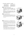
(B) For 230V : 3-10HP, 460V : 3-10HP
y MA7200-2003-N1
y MA7200-2005-N1
y MA7200-2007-N1
y MA7200-2010-N1
y MA7200-4003-N1
y MA7200-4005-N1
y MA7200-4007-N1
y MA7200-4010-N1
■ Removing the digital operator
Take off the screws in the place a. and b.
Press the lever on the side of the digital operator
in the direction of arrow 1 to unlock the digital
operator.
Disconnect the RS-232 cable connector on the
back side of the LCD digital operator. Lift the
digital operator in the direction of arrow 2 to
remove the digital operator.
■ Removing the front cover
Press the left and right sides of the front cover in
the directions of arrow 1 and lift the bottom of the
cover in the direction of arrow 2 to remove the
front cover.
LCD Digital Operator
Front Cover
2
1
b
Front
Cover
1
RS-232
Cable
Connector
2
c
■ Mounting the front cover and digital operator
Insert the tab of the upper part of front cover into
the groove of the inverter and press the lower part
of the front cover onto the inverter until the front
cover snaps shut.
Connecting the RS-232 cable connector on the
back side of the LCD digital operator and hook
the digital operator at a on the front cover in the
direction of arrow 1.
Press the digital operator in the direction of arrow
2 until it snaps in the place b and then tighten the
screws in the place c and d. (on the front cover)
1-5
a
1
Digital
Operator
Front
Cover
e
c
d
a
b
1
2
RS-232
Cable
Connector
(C) For 230V 15,20HP and 460V 15,20HP Series
y MA7200-2015-N1
y MA7200-4015-N1
y MA7200-2020-N1
y MA7200-4020-N1
■ Removing
the
digital
operator
:
Take off the screws in the place a. and b.
Disconnect the RS-232 cable connector on the
back side of the LCD digital operator and then lift
the digital operator upwards.
■ Removing
the
front
cover
:
Loosen the two screws of the front cover in the
place c and d. And lift the bottom of the front
cover to remove the front cover.
■ Mounting the front cover and digital operator :
Insert the tab of the upper part of front cover into
the groove of the inverter and tighten the screws
in the place c and d.
Connect the RS-232 cable connector on the back
of
the
LCD
digital
operator.
Attach the digital operator and tighten the screws
in the place a and b.
(D) For 230V 30~40HP and 460V 40~75HP Series
■ Removing the front cover:
Loosen the two screws
Front cover
of the front cover in the place a. and b. Then
loosen the two screws c and d, lift the front cover
upwards. (Don’t removing the digital operator.)
■ Mounting the front cover: Press the front cover
and then tighten the screws in the place a, b, c and
d.
1-6
a
b
d
Front
Cover
c
LCD Digital
Operator
RS-232 Cable
Connector
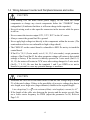
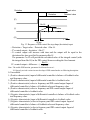
1.4 Wiring between Inverter and Peripheral devices and notice
CAUTION
1. After turning OFF the main circuit power supply, do not touch the circuit
components or change any circuit components before the “CHARGE” lamps
extinguished. (It indicates that there is still some charge in the capacitor).
2. Never do wiring work or take apart the connectors in the inverter while the power
is still on.
3. Never connect the inverter output U/T1, V/T2, W/T3 to the AC source.
4. Always connect the ground lead E to ground.
5. Never apply high voltage test directly to the components within the inverter. (The
semiconductor devices are vulnerable to high voltage shock.)
6. The CMOS IC on the control board is vulnerable to ESD. Do not try to touch the
control board.
7. If Sn-03 is 7,9,11 (2-wire mode) or is 8, 10, 12 (3-wire mode), except parameter
settings of Sn-01 and Sn-02, the other parameter settings will return to their initial
settings at factory. If the inverter is initially operated in 3-wire mode (Sn-03= 8,
10, 12), the motor will rotate in CCW sense after setting changed to 2-wire mode.
(Sn-03= 7, 9, 11). Be sure that the terminals 1 and 2 are OPEN so as not to
harmful to personal or cause any potential damage to machines.
CAUTION
1. Determine the wire size for the main circuit so that the line voltage drop is within
2% of the rated voltage. If there is the possibility of excessive voltage drop due to
wire length, use a larger wire (larger diameter) suitable to the required length
Line voltage drop(V) = 3 × wire resistance(Ω/km) × wire length(m) × current(A) × 10 -3
2. If the length of the cable wire between the inverter and the motor exceeds 30m,
use a lower carrier frequency for PWM (adjust the parameter Cn-34). Refer to
Page 3-21
1-7
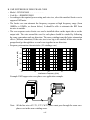
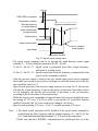
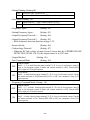
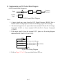
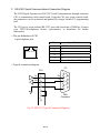
Example of connection between the MA7200 and typical peripheral devices are shown as below.
MCCB (Molded-Case Circuit Breaker)
Power supply
y Choose the Molded Case Circuit Breaker (MCCB) of
proper current rating. Please refer to the selection guide
Power supply
“1.10 Peripheral Units” on Page 1-22.
switch(NFB)
y Do not use a circuit breaker for start/stop operation.
and earth
y When a ground fault interrupter is used, select the one with
leakage
no influence for high frequency. Setting current should be
breaker
200mA or above and the operating time at 0.1 second or
longer to avoid false triggering.
Electromagnetic
contactor
AC reactor
Input noise
filter
MA 7200
inverter
Zero phase
core
MC (Magnetic Contactor)
y It is not always necessary to have a Magnetic Contactor on
the input side. However, an input Magnetic Contactor can
be used to prevent an automatic restart after recovery from
an external power loss during remote control operation.
y Do not use the Magnetic Contactor for start/stop operation.
AC Reactor
y To improve power factor or to reduce surge current, install
an AC Reactor on the input side of the MA7200.
Input Noise Filter
y When used with TECO specified Input Noise Filter, the
MA7200 will comply with EN55011 class A regulation.
y Please refer to the selection guide “1.10 Peripheral Units”
on page 1-22.
MA7200 Inverter
y The input power supply can be connected to any terminal
R/L1, S/L2, T/L3 on the terminal block.
y Please connect the ground terminal E to the site ground
securely.
Output Noise Filter (Zero Phase Core)
y Install an Output Noise Filter between the MA7200 and the
Induction Motor to eliminate noise transmitted between the
power line and the inverter.
y Please refer to the selection guide “1.10 Peripheral
Devices” on page 1-22.
Induction Motor
Induction
motor
y When multiple motors are driven in parallel with an
inverter, the inverter rated current should be at least 1.1
times the total motor rated current.
y The inverter and the motor must be separately grounded.
1-8
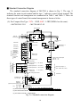
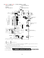
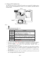
■ Standard Connection Diagram
The standard connection diagram of MA7200 is shown in Fig. 2. The sign ◎
indicates the main circuit terminal and the sign ○ indicates control circuit terminal. The
terminal function and arrangement are summarized in Table 1 and Table 2. There are
three types of control board, the terminal arrangement is shown as below.
(A) For Compact Size Type 230V : 1-2HP, 460V : 1-2HP (NEMA4 are the same)
•MA7200-2001/2-N1
•MA7200-4001/2-N1
Braking Resistor
B1/P
MC
NFB
Main Ckt
Power Supply
B2
R/L1
S/L2
T/L3
U/T1
V/T2
W/T3
IM
EXTERNAL FREQUENCY
COMMAND
Factory Preset
E
FWD/STOP
1
FWD
("Close":FWD)
REV/STOP
2
REV
("Close":REV)
External Fault
3
Eb
Fault RESET
4
Multi-Step
Speed Ref.1
5
Multi-Step
Speed Red.2
6
Jogging
Acc. & Dec.
Switch
7
2kΩ
1/2W
Analog
Output 1
Analog
Output 2
Multi-Function
Contact Input
+12V Power Supply for
Speed Ref.
0 ~ +10V
P
0V
PG INPUT
(A PHASE)
Analog Monitor 1, 2
(DC 0 ~ 10 V)
Multi-Function Contact Output
250V AC, <1A
30V DC, <1A
RB
RC
(+12V, 20 mA)
DO1
DO2
Multi-Function Output 1, 2
(Open Collector 48V, 50mA)
AIN Master Speed Ref. 4 ~ 20 mA, (250Ω)
P
AUX Multi-Funtion
Analog Input
P
0 ~ 10V, (20kΩ )
GND Analog signal Common
(*1)
EXTERNAL PG
DC VOLTAGE
AO2
GND
RA
VIN Master Speed Ref. 0 ~ 10V, (20kΩ )
4 ~ 20 mA
AO1
RESET
8
SC (DG)
Digital signal Common
E Shield Sheath
0 ~ +10V
Grounding Lead
(<100 Ω)
DOG
S(+)
S(-)
CN2
IP12 1
IG12 2
(*4)
RS-485 Port
TP1
OPEN
IP12
PULL UP
A(+) 3
(*4)Pulse Input Frequency CommandA(-) 4
(*1)
Shield
Wire
P
Shielded
Twisted Wire
(*2) The terminal arrangement
SC
E
1
3
2
5
4
7
6
8
VIN AIN AUX DO1 DO2 DOG S(-)
+12V GND GND AO1 AO2 S(+) E
(*3) The control board code No. : 4P101C0040001
(*4) The CN2 wire code No. : 4H339D0250001
Fig. 2-a Standard connection diagram
1-9
RA RB RC
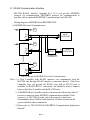
(B) 230V : 3-40HP, 460V : 3-75HP (NEMA4 to 20HP)
y MA7200-2003-N1
through
MA7200-2040-N1
y MA7200-4003-N1
through
MA7200-4075-N1
Braking Resistor
B1/P
NFB
MC
Main Ckt
Power Supply
B2
R/L1
S/L2
T/L3
U/T1
V/T2
W/T3
IM
Factory Preset
E
FWD/STOP
1
FWD
("Close":FWD)
REV/STOP
2
REV
("Close":REV)
External Fault
3
Eb
Fault RESET
4
Multi-Step
Speed Ref.1
5
Multi-Step
Speed Red.2
6
Jogging
7
Acc. & Dec.
Switch
8
Analog
Output 1
Analog
Output 2
TP2 :
EXTERNAL FREQUENCY
COMMAND
+12V or -12V Power Supply
for Speed Ref.
VIN Master Speed Ref.
AIN Master Speed Ref.
P
R2A
R2C
SINK
(±12V, 20 mA)
0 ~ 10V & -10V~10V
, (20kΩ)
4 ~ 20 mA, (250 Ω )
DO1
Multi-Function Output 1
(Open Collector 48V, 50mA)
DOG
GND Analog signal Common
(*1)
IP12
IG12
EXTERNAL PG
DC VOLTAGE
Multi-Function Contact Output
250V AC, <1A
30V DC, <1A
R1C
SOURCE
AUX Multi-Function
0 ~ 10V, (20k Ω )
Analog Input
(20 KΩ)
P
0V
(* 2)
TP2
4 ~ 20 mA
0 ~ +10V
GND
R1B
Multi-Function
Contact Input
E Shield Sheath
P
Analog Monitor 1, 2
(DC 0 ~ 10 V)
AO2
R1A
24V
(Source Common)
-10V ~ +10V
AO1
RESET
24VG
TP2 :
(Sink Common) SINK
2kΩ
1/2W
Grounding Lead
(<100 Ω)
TP1
OPEN
IP12
PULL UP
S(+)
S(-)
RS-485 Port
A(+)
PG INPUT
(A PHASE)
A(-)
(*4)Pulse Input Frequency Command
(*1)
Shield
Wire
P
Shielded
Twisted Wire
8 can be set as SINK or SOURCE type input interface, when setting
The
elde Tw isted W ire
(*1) (*2)Shi
eldterminal
W ire 1 P~Shi
1 ~ 8 as sink type
input, the short jumper of TP2 must be set to SINK position, and set to SOURCE position for source type input.
(*2)The term inalc and
j can be set as SIN K or1 S O3U RCE
type inputinterface,w hen settingc~j as sink type input,the shortjum per ofTP2
5
7 24V VIN AIN AUX DO1 DOG IP12 A(+) A(-)
(*3) The terminal arrangement
24VG
2
4
+12VGND GND AO1 AO2 E IG12 S(+) S(-)
R2A R2C R1A R1B R1C
m ustbe setto SIN K position,andsetto SOEU RCE
posi
tion6 for8sour
ce type input.
IN Ref
.can
be setboard
in tw ocode
inputmNo.
ethods
as 0~10V or-10~+10V
(*3) V(*4)
The
control
: 4P101C0060002
(*4) The term inalA (+),A (-)can be the outputterm inalof Pulse InputFrequency Com m and,and the jum per ofTP1 m ustbe setto O PEN position.
Pulse InputFrequency Com m and:0~32K H z,3~12V H igh torsion,inputresistor2.7K Ω
3 5
7 24V VIN AIN AUX DO1 DOG IP12 A(+) A(-)
(*5) The term inalarrangem ent 24VG 1
E Fig.
2 42-b6 Standard
8 +12V -12Vconnection
GND AO1 AO2 Ediagram
R2A R2C R1A R1B R1C
IG12 S(+) S(-)
(*6) The controlboard code N o.:4P101C0130001
Fig. 2-b Standard connection diagram
1-10
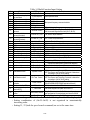
1.5 Description of terminal function
Table 1 Main circuit terminals
Terminal
R/L1
S/L2
T/L3
B1/P
B2
Θ
⊕
B2/R
U/T1
V/T2
W/T3
E
230V:1~20HP, 460V:1~20HP
230V:25~40HP, 460V:25~75HP
Main circuit input power supply
(For single phase power supply, please use R/L1, S/L2 as input terminal)
-
B1/P, B2: External braking resistor
B1/P, Θ: DC power supply input
• ⊕ - \ : DC power supply or
braking unit
-
Unused
Inverter output
Grounding lead (3rd type grounding)
■ Terminal block configuration
․230V : 1 ~ 2HP
․ 460V : 1 ~ 2HP
J4
R/L1 S/L2 T/L3 B1/P
B2 U/T1 V/T2 W/T3
B1/P
J2
B2
R/L1 S/L2 T/L3 U/T1 V/T2 W/T3
․230V : 3~5HP
E
R/L1 S/L2 T/L3
Power In
B1/P B1/R B2
Dynamic Brake
U/T1 V/T2
To Motor
CHARGE
W/T3
․460V : 3~5HP
E
R/L1 S/L2 T/L3
Power In
B1/P B2
Dynamic Brake
U/T1 V/T2
To Motor
CHARGE
W/T3
․230V/460V : 7.5~10HP
E
R/L1 S/L2 T/L3
Power In
B1/P B1/R B2
Dynamic Brake
U/T1 V/T2 W/T3
To Motor
CHARGE
․230V/460V : 15~20HP
R/L1 S/L2 T/L3
E
․ 230V : 25~40HP, 460V : 25~75HP
B1/P B2 U/T1 V/T2 W/T3
R/L1 S/L2 T/L3
1-11
U/T1 V/T2 W/T3
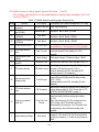
Table 2 Control circuit terminals
Terminal
1(DI1)
2(DI2)
3(DI3)
4(DI4)
5(DI5)
6(DI6)
7(DI7)
8(DI8)
SC(DG)
(24VG)
24V
E
+15V(+12V)
-12V
VIN
AIN
AUX
GND
IP12
IG12
A(+)
A(-)
AO1
AO2
GND
RA(R1A)
RB(R1B)
RC(R1C)
Functions
Forward Operation – Stop Signal
Reverse Operation – Stop Signal
External Fault Input
Fault Reset
Multifunction Input Terminal: 3-Wire Operation, Load/Remote Control, Multi-Speed Select,
FWD/REV Select, ACC/DEC Choice, ACC/DEC Halting, Base Block, Overheat Warn, PID
Control, DC Braking, Speed Search, Up/Down Function, PG Feedback Control, External Fault,
Timer function, Multifunction Analog Input Setting
Digital Signal Ground
Sink Common Point (Locate the short jumper of TP2 in SINK position)
Source Common Point (Locate the short jumper of TP2 in SOURCE position)
Connection to Shield Signal Lead (Frame Ground)
DC voltage for External Device
Only support by the board 4P101C01301
Master speed Voltage Reference (0~10V) (4P101C01301 support –10V~10V input)
Master speed Current Reference (4~20mA)
Auxiliary Analog Input:
Auxiliary frequency Command, Frequency Gain, Frequency Bias, Overtorque Detection, Output
Voltage Bias, ACC/DEC Ramp, DC-Brake Current, Stall Prevention Current Level during
Running Mode, PID Control, Lower-Bound of Frequency Command, Frequency-Jump-4, etc
Analog Signal Common
External Power Source For PG Feedback Use
Signal Input of PG (also can be the input terminal of Pulse Input Frequency Command)
Analog
Multifunction
Output
Port:
Frequency Commend, Output Frequency, Output Current, Output Voltage, DC Voltage, PID
Controlled Value, Analog Command Input of VIN, AIN or AUX.(Below 2mA)
Common Lead for Analog Port
Relay Contact Output A
Same function as terminal DO1,
Relay Contact Output B
DO2
Relay Contact Common
Digital Multi-Function (Open Collector) Output “1”, “2” Terminals:
During-Running, Zero-speed, Agreed-frequency, Agree-frequency-setting, Frequency-Output,
Inverter-Operation-Ready, Undervoltage-Detection, Base-Block Output, Run Source, Frequency
R2A command, Overtorque Detection, Frequency Command Invalid, Fault, Undervoltage, Overheat,
DO2 (
)
R2B Motor Overload, Inverter Overload, During-Retry, Communication-Fault, Timer-Function-Output
DO1
DOG
S(+)
S(-)
Common Terminal (of Open Collector Transistor)
RS-485 Port
Caution
• Use the control circuit terminals VIN, AIN according the setting of Sn-24.
• The MAX. Output current at terminal (+15V or +12V) is 20mA.
• The multi-function analog output terminals AO1, AO2 is a dedicated output for a frequency meter, ammeter,
etc. Do not use these 2 analog outputs for feedback control or any other control purpose.
1-12
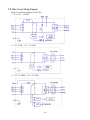
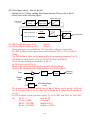
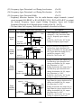
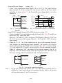
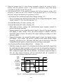
1.6 Main Circuit Wiring Diagram
Main Circuit Wiring Diagram of MA7200:
1. 230V/460V : 1~20HP
2. 230V : 25HP 460V : 25~30HP
3. 230V : 30~40HP 460V : 40~75HP
1-13
1.7 Wiring main circuit and notice
■ Main circuit wiring
The non-fusible-breaker (NFB) should be installed between the AC source and the
R/L1-S/L2-T/L3 input terminal of MA7200 inverter. The user can make his own decision
of installing electromagnetic contactor block (MCB) or not. To protect against the false
triggering of leakage-current, the user should install a leakage current breaker with
amperage sensitivity≧200mA and operation time≧0.1 sec.
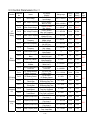
Table 3 230V and 460V class applicable wire size and connector
Power
supply
230V
1Φ/3Φ
230V
3Φ
460V
3Φ
MA7200 model
Applicable
Rated
Power Rating
KVA
(HP)*1
1HP
2HP
3HP
5.4HP
7.5HP
10HP
15HP
20HP
25HP
30HP
40HP
1HP
2HP
3HP
5.4HP
7.5HP
10HP
15HP
20HP
25HP
30HP
40HP
50HP
60HP
75HP
2
2.7
4
7.5
10.1
13.7
20.6
27.4
34
41
54
2.2
3.4
4.1
7.5
10.3
12.3
20.6
27.4
34
41
54
68
82
110
Rated
current
(A)
4.8
6.4
9.6
17.5
24
32
48
64
80
96
130
2.6
4
4.8
8.7
12
15
24
32
40
48
64
80
96
128
Wire size (mm2)
Ground
Main
Control
connection
circuit*2
wire*3
wire E (G)
2~5.5
2~5.5
3.5~5.5
5.5
8
8
14
22
22
38
60
2~5.5
2~5.5
2~5.5
2~5.5
3~5.5
5.5
8
8
8
14
22
22
38
60
2~5.5
3.5~5.5
3.5~5.5
5.5
5.5~8
5.5~8
8
8
14
14
22
2~5.5
3.5~5.5
3.5~5.5
3.5~5.5
3.5~5.5
5.5
8
8
8
8
8
14
14
22
0.5~2
0.5~2
0.5~2
0.5~2
0.5~2
0.5~2
0.5~2
0.5~2
0.5~2
0.5~2
0.5~2
0.5~2
0.5~2
0.5~2
0.5~2
0.5~2
0.5~2
0.5~2
0.5~2
0.5~2
0.5~2
0.5~2
0.5~2
0.5~2
0.5~2
NFB*4
MCB*4
TO-50EC(15A)
TO-50EC(20A)
TO-50EC(20A)
TO-50EC(30A)
TO-100S(50A)
TO-100S(60A)
TO-100S(100A)
TO-100S(100A)
TO-225S(150A)
TO-225S(175A)
TO-225S(175A)
TO-50EC(15A)
TO-50EC(15A)
TO-50EC(15A)
TO-50EC(15A)
TO-50EC(20A)
TO-50EC(30A)
TO-50EC(30A)
TO-100S(50A)
TO-100S(75A)
TO-100S(100A)
TO-100S(100A)
TO-125S(125A)
TO-225S(175A)
TO-225S(175A)
CN-11
CN-11
CN-11
CN-16
CN-18
CN-25
CN-50
CN-65
CN-80
CN-100
CN-125
CN-11
CN-11
CN-11
CN-18
CN-18
CN-25
CN-25
CN-35
CN-50
CN-50
CN-65
CN-80
CN-100
CN-125
*1 : It is assumed constant torque load.
*2 : The main circuit has terminals of R/L1, S/L2, T/L3, U/T1, V/T2, W/T3, B1/P, B2/R, B2,Θ.
*3 : The control wire is the wire led to the pin terminals of control board.
*4 : In Table 3, the specified Part No. of NFB and MC are the item No. of the products of TECO. The
customer can use the same rating of similar products from other sources. To decrease the noise
interference, be sure to add R-C surge suppressor (R: 10Ω/5W, C: 0.1µF/1000VDC) at the 2
terminals of coils of electromagnetic contactor.
1-14
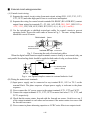
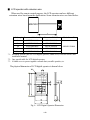
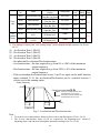
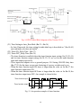
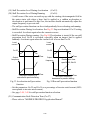
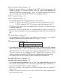
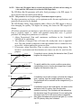
■ External circuit wiring precaution:
(A) Control circuit wiring:
(1) Separate the control circuit wiring from main circuit wiring (R/L1, S/L2, T/L3, U/T1,
V/T2, W/T3) and other high-power lines to avoid noise interruption.
(2) Separate the wiring for control circuit terminals RA-RB-RC (R1A-R2B-R2C) (contact
output) from wiring for terminals c~j, A01, A02, GND, DO1, DO2 , DOG 15V(or
+12V, -12V), VIN, AIN, AUX, GND, IP12, IG12, A (+), A (-), S(+) and S(-).
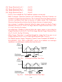
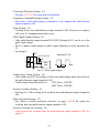
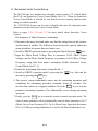
(3) Use the twisted-pair or shielded twisted-pair cables for control circuits to prevent
operating faults. Process the cable ends as shown in Fig. 3. The max. wiring distance
should not exceed 50 meter.
Shield sheath
Armor
Connect to shield
sheath terminal E
Do not
Insulated with tape connect here
Fig. 3. Processing the ends of twisted-pair cables
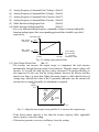
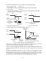
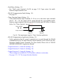
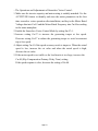
When the digital multi-function output terminals connect serially to an external relay, an
anti-parallel freewheeling diode should be applied at both ends of relay, as shown below.
50 mA max.
48V max.
free-wheeling diode
(100V, >100mA)
MA7200
7200MA
external wiring circuit
Fig. 4. The Optical-couplers connect to external inductive load
(B) Wiring the main circuit terminals:
(1) Input power supply can be connected to any terminal R/L1, S/L2 or T/L3 on the
terminal block. The phase sequence of input power supply is irrelevant to the phase
sequence.
(2) Never connect the AC power source to the output terminals U/T1, V/T2 and. W/T3.
(3) Connect the output terminals U/T1, V/T2, W/T3 to motor lead wires U/T1, V/T2, and
W/T3, respectively.
(4) Check that the motor rotates forward with the forward run source. Switch over any 2
of the output terminals to each other and reconnect if the motor rotates in reverse with
the forward run source.
(5) Never connect a phase advancing capacitor or LC/RC noise filter to an output circuit.
1-15
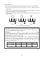
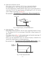
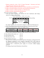
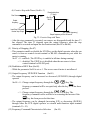
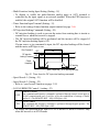
(C) GROUNDING :
(1) Always use the ground terminal (E) with a ground resistance of less than 100Ω.
(2) Do not share the ground wire with other devices, such as welding machines or
power tools.
(3) Always use a ground wire that complies with the technical standards on electrical
equipment and minimize the length of ground wire.
(4) When using more than one inverter, be careful not to loop the ground wire, as
shown below.
(a) OK
(b) OK
(c) NO
Fig. 5. MA7200 ground winding
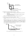
• Determine the wire size for the main circuit so that the line voltage drop is within
2% of the rated voltage. (If there is the possibility of excessive voltage drop, use a
larger wire suitable to the required length)
• Installing
an
AC
reactor
If the inverter is connected to a large-capacity power source (600kVA or more),
install an optional AC reactor on the input side of the inverter. This also improves
the power factor on the power supply side.
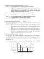
• If the cable between the inverter and the motor is long, the high-frequency
leakage current will increase, causing the inverter output current to increase as
well. This may affect peripheral devices. To prevent this, adjust the carrier
frequency, as shown below:
Cable length
Carrier frequency
(Cn-34)
< 100ft.
100-165ft.
166-328ft.
15kHz max 10kHz max 5kHz max
(Cn-34=6) (Cn-34=4) (Cn-34=2)
1-16
> 329ft.
2.5kHz
(Cn-34=1)
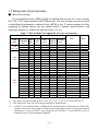
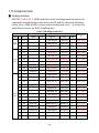
1.8 Inverter Specifications
Basic Specifications
(a) 230V Series
Inverter (HP)
1
2
3
5
7.5
10
15
20
25
30
40
40
(30)
54
130
Power Supply
Output Characteristics
Max. Applicable Motor
1
2
3
5.4
7.5
10
15
20
25
30
Output HP*1 (KW)
(0.75) (1.5) (2.2)
(4)
(5.5) (7.5)
(11)
(15) (18.5) (22)
Rated Output
2
2.7
4
7.5
10.1
13.7
20.6
27.4
34
41
Capacity (KVA)
Rated Output
4.8
6.4
9.6
17.5
24
32
48
64
80
96
Current (A)
Max. Output Voltage
3-Phases, 200V~230V
(V)
Max. Output
Through Parameter Setting 0.1~400.0 Hz
Frequency (Hz)
Rated Voltage,
1PH/3PH 200V~230V,
3-Phases, 200V~230V, 50/60Hz
Frequency
50/60Hz
Allowable Voltage
-15% ~ +10%
Fluctuation
Allowable Frequency
±5%
Fluctuation
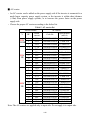
(b) 460V Series
Power Supply
Output Characteristics
Inverter (HP)
1
2
3
1
Max. Applicable Motor
2
3
Output HP*1 (KW)
(0.75) (1.5) (2.2)
Rated Output
2.2 3.4 4.1
Capacity (KVA)
Rated Output
2.6
4
4.8
Current (A)
Max. Output Voltage
(V)
Max. Output
Frequency (Hz)
Rated Voltage,
Frequency
Allowable Voltage
Fluctuation
Allowable Frequency
Fluctuation
5
5.4
(4)
7.5
10
15
7.5
10
15
(5.5) (7.5) (11)
7.5
10.3 12.3 20.6 27.4
8.7
12
15
24
20
25
30
40
50
60
75
20
25
30
40
50
60
75
(15) (18.5) (22) (30) (37) (45) (55)
32
34
41
54
68
82
110
40
48
64
80
96
128
3-Phases, 380V~460V
Through Parameter Setting 0.1~400.0 Hz
3-Phases, 380V ~ 460V, 50/60Hz
-15% ~ +10%
±5%
*1. Based on 4 pole motor
*2. The spec. of NEMA4 are the same
1-17
General Specifications
Graphic LCD Panel (English and Chinese) with parameters copying (LED:
option)
Control Mode
Sinusoidal PWM
Frequency Control Range 0.1Hz ~ 400Hz
Frequency Accuracy
Digital Command: ±0.01% (-10 ~ +40ºC),
Analog Command: ±0.1% (25ºC±10ºC),
(varied with temperature)
Speed Control Accuracy
±0.1%(V/F with PG feedback), ±0.5%(Sensorless Vector Control)
Frequency Command
Digital Command: 0.01Hz Analog Command: 0.06Hz/60Hz
Resolution
Frequency Output
0.01Hz
Resolution
Overload Resistibility
150% Rated Current for 1 Min
DC 0~+10V / 4~20 mA, DC-10V~+10V and Pulse Input Frequency Command
Frequency Setting Signal
(Above 230V/460V 3HP)
Acc./Dec. Time
0.0~6000.0 sec ( Accel/Decel Time Can Be Set Independently)
Voltage–Frequency
V/F Curve Can Be Set Through Parameter Setting
Characteristics
Regeneration Torque
Approx. 20%
Restart After Momentary Power Loss, PID Control, Auto Torque Boost, Slip
Basic Control Function
Compensation, RS_485 Communication, Speed Feedback Control, Simple
PLC function, 2 Analog Output Port
Cumulative Power on & Operation Hour memory, Energy Saving, Up/Down
Operation, 4 Different sets of Fault Status Record (Including Latest one),
Extra Function
MODBUS Communication, Multiple-Pulse Output Ports, Select Local/Remote,
Customer Application Software Environment (C.A.S.E), SINK/SOURCE
Interface.
During
Acceleration/Deceleration
and
constant
Speed
Running
Stall Prevention
(Current Level Can Be Selected During Acceleration and Constant Speed
Running. During Deceleration, Stall Prevention Can Be Enabled or Disabled)
Instantaneous
Stopped if above 200% Rated Current
Overcurrent
Motor Overload Protection Electronic Overload Curve Protection
Inverter Overload
Stopped if above 150% Rated Current for 1 Min.
Protection
Overvoltage
Stop if VDC 410V (230 Class) or VDC 820V (460 Class)
Undervoltage
Stop if VDC 200V (230 Class) or VDC 400V (460 Class)
Momentary Power Loss
15ms, stop otherwise
Ride-Through time
Overheat Protection
Protected by Thermistor
Grounding Protection
Protection by DC Current Sensor
Charge Indication (LED)
Lit when the DC Bus Voltage Above 50V
Input Phase Loss (IPL)
Motor coasts to stop at Input Phase Loss
Output Phase Loss (OPL) Motor coasts to stop at Output Phase Loss
Application Site
Indoor (No Corrosive Gas And Dust Present)
Ambient Temperature
-10ºC ~ +40ºC (Not Frozen)
Storage Temperature
-20ºC ~ +60ºC
Ambient Humidity
Below 90%RH (Non-Condensing)
Height, Vibration
Below 1000M, 5.9m/S2 (0.6G), (JISC0911 Standard)
Communication Function
RS-485 Installed (MODBUS Protocol)
Built-in PG Feedback Interface and set to Open-collector Interface Drive or
Encoder Feedback Interface
Complementary Interface Drive
EMI
Meet EN 61800-3 With Specified EMI Filter
EMS Compatibility
Meet EN 61800-3
Option
PROFIBUS Card
Environmental
Condition
Protection Function
Control Characteristics
Operation Mode
1-18
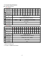
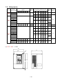
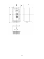
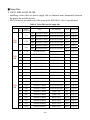
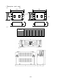
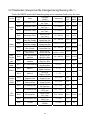
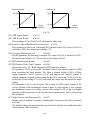
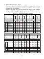
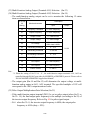
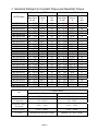
1.9 Dimensions
Voltage
230V
1/3Φ
230V
3Φ
460V
3Φ
Inverter
Capacity(HP)
1
2
3
5
7.5
10
15
20
25
30
40
1
2
3
5
7.5
10
15
20
25
30
40
50
60
75
Open Chassis Type (IP00)
(mm)
W H D W1 H1 d
Weight
(kg)
-
Enclosed Type (NEMA1) (mm)
W
132
H
D
W1 H1
d
Weight Reference
(kg)
Figure
217 143.5 122 207 M5
2.3
140 279.5 176.5 126 226 M6
140 279.5 176.5 126 226 M6
4.3
4.3
211.2 300
215 192 286 M6
5.7
-
(b)
265
269 553 277 210 530 M10
30
31
-
(a)
360
225 245 340 M6
13
31
32
(c)
(a)
269
647
132
217 143.5 122 207 M5
2.3
140 279.5 176.5 126 226 M6
4.3
211.2 300
277 210 530 M10
12
215 192 286 M6
5.7
(b)
12
265
360
225 245 340 M6
13
269 553 277 210 530 M10
30
269
647
277 210 530 M10
31
308 653 282 250 630 M10
46
308
747
282 250 630 M10
47
(c)
(a) 230V / 460V : 1~2HP
W
W1
D
d
H
1
H
H
2
1-19
(b) 230V : 3HP~25HP
460V : 3HP~30HP
1
1
(c) 230V : 30HP~40HP
460V : 40HP~75HP
W
W1
W
D
D
H
H
H1
H1
W1
(Open Chassis Type-IP00)
(Enclosed, Wall-mounted Type-NEMA1)
d
d
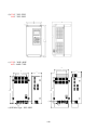
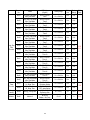
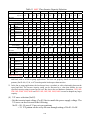
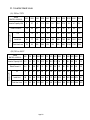
(d) NEMA4 Type : 1HP~20HP
1-20
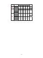
Voltage
230V
1/3Φ
230V
3Φ
460V
3Φ
Inverter
Capacity(HP)
1
2
3
5
7.5
10
15
20
1
2
3
5
7.5
10
15
20
NEMA4 (mm)
D
W1 H1
d
Weight
(kg)
W
H
198
335
217
115
315
M6
198
335
217
115
315
M6
7.5
7.5
223
460
245
140
440
M6
16
198
335
217
115
315
M6
6.3
6.3
7.5
223
460
245
1-21
140
440
M6
16
1-22
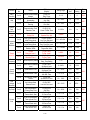
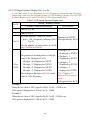
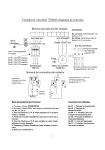
1.10 Peripheral Units
■ Braking resistors
MA7200 230V/460V 1~20HP model have built-in braking transistor, and can be
connected external braking resistor between B1/P and B2 when lack of braking
ability. Above 25HP models, need to connect braking unit (on ⊕ - \ of inverter)
and braking resistors (on B-P0 of braking unit).
Table 4 Braking resistor list
Inverter
Rated
Voltage HP
current (A)
230V
1/3Φ
230V
3Φ
460V
3Φ
Braking Unit
Number
Model
used
Braking Resistor
Code NO.
Specs.
Number
used
Braking Torque
(%)
1
4.8
-
-
JNBR-150W200
150W/200Ω
1
119%, 10%ED
2
6.4
-
-
JNBR-150W100
150W/100Ω
1
119%, 10%ED
3
9.6
-
-
JNBR-260W70
260W/70Ω
1
115%, 10%ED
5
17.5
-
-
JNBR-390W40
390W/40Ω
1
119%, 10%ED
7.5
24
-
-
JNBR-520W30
520W/30Ω
1
108%, 10%ED
10
32
-
-
JNBR-780W20
780W/20Ω
1
119%, 10%ED
15
48
-
-
JNBR-2R4KW13R6
2400W/13.6Ω
1
117%, 10%ED
20
64
-
-
JNBR-3KW10
3000W/10Ω
1
119%, 10%ED
25
80
JNTBU-230
1
JNBR-4R8KW8
4800W/8Ω
1
119%, 10%ED
30
96
JNTBU-230
1
JNBR-4R8KW6R8
4800W/6.8Ω
1
117%, 10%ED
40
130
JNTBU-230
2
JNBR-3KW10
3000W/10Ω
2
119%, 10%ED
1
2.6
-
-
JNBR-150W750
150W/750Ω
1
126%, 10%ED
2
4
-
-
JNBR-150W400
150W/400Ω
1
119%, 10%ED
3
4.8
-
-
JNBR-260W250
260W/250Ω
1
126%, 10%ED
5
8.7
-
-
JNBR-400W150
400W/150Ω
1
126%, 10%ED
7.5
12
-
-
JNBR-600W130
600W/130Ω
1
102%, 10%ED
10
15
-
-
JNBR-800W100
800W/100Ω
1
99%, 10%ED
15
24
-
-
JNBR-1R6KW50
1600W/50Ω
1
126%, 10%ED
20
32
-
-
JNBR-1R5KW50
1500W/40Ω
1
119%, 10%ED
25
40
JNTBU-430
1
JNBR-4R8KW32
4800W/32Ω
1
119%, 10%ED
30
48
JNTBU-430
1
JNBR-4R8KW27R2
4800W/27.2Ω
1
117%, 10%ED
40
64
JNTBU-430
1
JNBR-6KW20
6000W/20Ω
1
119%, 10%ED
50
80
JNVPHV-0060
1
JNBR-9R6KW16
9600W/16Ω
1
119%, 10%ED
60
96
JNVPHV-0060
1
JNBR-9R6KW13R6
9600W/13.6Ω
1
117%, 10%ED
75
128
JNTBU-430
2
JNBR-6KW20
6000W/20Ω
2
126%, 10%ED
1-23
■ AC reactor
• An AC reactor can be added on the power supply side if the inverter is connected to a
much larger capacity power supply system, or the inverter is within short distance
(<10m) from power supply systems, or to increase the power factor on the power
supply side.
• Choose the proper AC reactor according to the below list.
Table 5 AC reactor list
Inverter Model
AC reactor
Specification
Rated
V
HP
Code No.
current
(mH/A)
1
4.8A
3M200D1610021
2.1mH/5A
230V
2
6.5A
3M200D1610030
1.1mH/10A
1Φ/3Φ
3
9.6A
3M200D1610048 0.71mH/15A
5.4
17.5A
3M200D1610056 0.53mH/20A
7.5
24A
3M200D1610064 0.35mH/30A
10
32A
3M200D1610072 0.265mH/40A
230V
15
48A
3M200D1610081 0.18mH/60A
3Φ
20
64A
3M200D1610099 0.13mH/80A
25
80A
0.12mH/90A
3M200D1610102
30
96A
3M200D1610111 0.09mH/120A
40
130A
3M200D1610269 0.07mH/160A
1
2.6A
3M200D1610137
8.4mH/3A
2
4A
3M200D1610145
4.2mH/5A
3
4.8A
3M200D1610153 3.6mH/7.5A
5.4
8.7A
3M200D1610161
2.2mH/10A
7.5
12A
3M200D1610170 1.42mH/15A
10
15A
3M200D1610188 1.06mH/20A
460V
15
24A
3M200D1610196
0.7mH/30A
3Φ
20
32A
3M200D1610200 0.53mH/40A
25
40A
0.42mH/50A
3M200D1610218
30
48A
0.36mH/60A
3M200D1610226
40
64A
0.26mH/80A
3M200D1610234
50
80A
0.24mH/90A
3M200D1610242
60
96A
0.18mH/120A
3M200D1610251
75
128A
3M200D1610315 0.15mH/150A
Note: The AC reactors are applied only to input side. Do not apply it to output side.
1-24
■ Noise filter
A. INPUT SIDE NOISE FILTER
• Installing a noise filter on power supply side to eliminate noise transmitted between
the power line and the inverter
• MA7200 has its specified noise filter to meet the EN61800-3 class A specification
Table 6 Noise filter on the input side
Inverter
V
230V
1/3Φ
230V
3Φ
460V
3Φ
Noise Filter
Rated
HP Current (A)
Code
Specifications
Current Dimensions
1Φ
4H300D1750003
JUNF12015S-MA
15 A
Fig. (a)
3Φ
4H300D1710001
JUNF32012S-MA
12 A
Fig. (a)
1Φ
4H300D1750003
JUNF12015S-MA
15 A
Fig. (a)
3Φ
4H300D1710001
JUNF32012S-MA
12 A
Fig. (a)
1Φ
4H300D1600001
JUNF12020S-MA
20 A
Fig. (a)
3Φ
4H300D1610007
JUNF32024S-MA
24 A
Fig. (a)
4H300D1610007
JUNF32024S-MA
24 A
24A
4H300D1620002
JUNF32048S-MA
48 A
Fig. (a)
Fig. (b)
10
32A
4H300D1620002
JUNF32048S-MA
48 A
Fig. (b)
15
48A
4H300D1730002
JUNF32070S-MA
70 A
Fig. (b)
20
64A
4H300D1730002
JUNF32070S-MA
70 A
Fig. (b)
1
2.6A
4H300D1720007
JUNF34008S-MA
8A
Fig. (a)
2
4A
4H300D1720007
JUNF34008S-MA
8A
Fig. (a)
3
4.8A
4H300D1630008
JUNF34012S-MA
12 A
Fig. (a)
5.4
8.7A
4H300D1630008
JUNF34012S-MA
12 A
Fig. (a)
7.5
12A
4H300D1640003
JUNF34024S-MA
24 A
Fig. (b)
10
15A
4H300D1640003
JUNF34024S-MA
24 A
Fig. (b)
15
24A
4H300D1740008
JUNF34048S-MA
48 A
Fig. (b)
20
32A
4H300D1740008
JUNF34048S-MA
48 A
Fig. (b)
25
40A
4H000D1770008
KMF370A
70A
Fig. (c)
30
48A
4H000D1790009
KMF370A
70A
Fig. (c)
40
64A
4H000D1790009
KMF3100A
100A
Fig. (c)
50
80A
4H000D1800004
KMF3100A
100A
Fig. (c)
60
96A
4H000D1800004
KMF3150A
150A
Fig. (c)
75
128A
4H000D1820005
KMF3180A
180A
Fig. (c)
1
4.8A
2
6.5A
3
9.6A
5.4
17.5A
7.5
1-25
• Dimension : (unit : mm)
(b)
250
125
L3
60
70
(c)
Model
KMF370A
KMF3100A
KMF3150A
KMF3180A
W
93
93
126
126
4 − φ 6.5
L1
LINE
L1
PE
PE
L2
L3
100 50
L2
L3
L2
2 −φ 6.5
L1
LOAD
L3
L2
PE
L1
80
LINE
40
225
LOAD
140
PE
(a)
W1
79
79
112
112
Dimension (mm)
H
H1
D
312 298
190
312 298
190
334 298
224
334 298
224
1-26
d
7
7
7
7
M
M6
M6
M6
M6
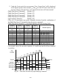
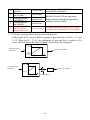
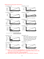
B. EMI SUPPRESSION ZERO PHASE CORE
• Model : JUNFOC046S -------
• Code No. : 4H000D0250001
• According to the required power rating and wire size, select the matched ferrite core to
suppress EMI noise.
• The ferrite core can attenuate the frequency response at high frequency range (from
100KHz to 50MHz, as shown below). It should be able to attenuate the RFI from
inverter to outside.
• The zero-sequence noise ferrite core can be installed either on the input side or on the
output side. The wire around the core for each phase should be winded by following
the same convention and one direction. The more winding turns the better attenuation
effect. (Without saturation). If the wire size is too big to be winded, all the wire can be
grouped and go through these several cores together in one direction.
• Frequency attenuation characteristics (10 windings case)
atteuatoin value (dB)
0
-10
-20
-30
-40
1
10
2
10
3
10
Interference Frequency (kHz)
4
10
5
10
Example: EMI suppression zero phase core application example
DRIVE FWD REV
REMOTE
DIGITAL OPERATOR JNEP-31
PRGM
DRIVE
JOG
FWD
REV
RUN
DSPL
EDIT
ENTER
RESET
STOP
Note: All the line wire of U/T1, V/T2, W/T3 phase must pass through the same zerophase core in the same winding sense.
1-27
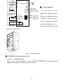
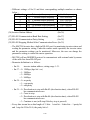
■ LCD operator with extension wire
When used for remote control purpose, the LCD operator can have different
extension wires based upon the applications. Some extension wires are listed below.
MA7200
L
Cable Length Extension Cable Set *1
1m
2m
3m
5m
10m
Extension Cable *2
Blank Cover *3
4H314C0010003
4H314C0030004
4H314C0020009
4H314C0040000
4H314C0060001
4H300D1120000
4H332D0010000
4H332D0030001
4H332D0020005
4H332D0040006
4H332D0130005
*1 : Including special cable for LCD digital operator, blank cover, fixed use screws and
installation manual.
*2 : One special cable for LCD digital operator.
*3 : A blank cover to protect against external dusts, metallic powder, etc.
The physical dimension of LCD digital operator is drawn below.
E
T
O
M
E
R
V
E
R
D
W
F
E
V
I
R
D
F
E
R
Q
E
S
1
3
P
E
N
J
R
O
T
A
R
E
P
O
L
A
T
I
G
I
D
E
V
I
R
D
L
P
S
D
M
G
R
P
R
T E
I
D T
E N
E
G
O
J
T
E
S
E
R
D V
W E
F R
P
O
T
S
N
U
R
Fig. 6. LCD Digital Operator Dimension
1-28
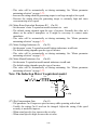
R/L1
S/L2
T/L3
BREAKER
FWD RUN
R/L1
S/L2
T/L3
B1/P
B2
MA7200
U/T1
V/T2
W/T3
1
RA
STOP
RB
RC
SC
Master Freq. Ref.
976Ω , 1/4 W
0 ~ 10V
2kΩ
FM
IM
(+15V, 20 mA)
15V Power Supply
for Speed Ref
.
VIN Master Speed
GND 0V
A01
GND
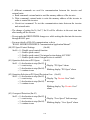
■ Analog operator
Multi-Function
Contact Output
250V AC, max. 1A
30V DC, max. 1A
digital LCD digital operator.
DO1
During
Running
DO2
Speed
Agree
DOG
All MA7200 have the
Multi-Function
Output 1, 2
(Open Collector
48V/50mA)
Moreover, an analog operator
as JNEP-16 (shown in fig. 7)
is also available and can be
ANALOG
OUTPUT
connected through wire as a
Analog Operator
portable operator. The wiring
diagram is shown below.
Fig. 7. Analog Operator
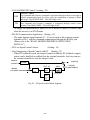
■ PROFIBUS Communication Card
• Code No. : 4H300D0290009
• Please refer to the appendix D and “MA7200 PROFIBUS-DP Communication
Application manual” for communication interface.
1-29
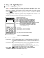
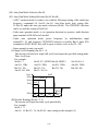
2. Using LCD Digital Operator
■ Functions of LCD digital operator
JNEP-36 LCD digital operator has 2 modes: DRIVE mode and PRGM mode. When
the inverter is stopped, DRIVE mode or PRGM mode can be selected by pressing
PRGM
DRIVE
the key
. In DRIVE mode, the operation is enabled. Instead, in the PRGM
mode, the parameter settings for operation can be changed but the operation is not
enabled. The component names and function are shown as below:
DRIVE
FWD
REV
REMOTE
SEQ
REF
DIGITAL OPERATOR JNEP-36
REMOTE/LOCAL
PRGM
DRIVE
DSPL
EDIT
JOG
ENTER
FWD
REV
RESET
RUN
operation mode indicators
DRIVE : lit when in DRIVE mode
FWD : lit when there is a forward run command input
REV : lit when there is a reverse run command input
SEQ : lit when the run command is enabled from the
control circuit terminal or RS-485 port (REMOTE mode)
REF : lit when the frequency reference from the control
circuit terminals (VIN or AIN) or RS-485 port is
enabled (REMOTE mode)
STOP
LCD Display
Chinese Display : 2-line by 8-character
English Display : 2-line by 20-character
Keys (Key functions are defined in Table 7)
Fig. 8. LCD Digital operator
• Remote/Local switch function:
• Local mode – RUN command input from LCD Digital Operator (SEQ LED off)
– Frequency command input from LCD Digital Operator (REF LED
off)
• Remote mode –RUN command input from control circuit (when Sn-04=1) or RS485 comm. port (when Sn-04=2) (SEQ LED lit)
–Frequency command input from control circuit (when Sn-05=1) or
RS-485 comm. port (when Sn-05=2) (REF LED lit)
JOG
RESETto switch Local/Remote mode. (Switching action of
• Press and both
Local/Remote only can be done while Inverter stop.)
2-1
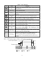
Table 7 Key's functions
Key
PRGM
DRIVE
Name
Function
PRGM/DRIVE Switches over between program mode (PRGM) and drive
key
mode (DRIVE).
DSPL
DSPL key
JOG
JOG key
FWD
REV
FWD/REV
key
Select the rotation direction from LCD digital operator.
RESET key
Set the number of digital for user constant settings. Also It
acts as the reset key when a fault has occurred.
RESET
INCREMENT
key
DECREMENT
key
EDIT
ENTER
RUN
STOP
Display operation status
Enable jog operation from LCD digital operator in operation
(DRIVE).
Select the menu items, groups, functions, and user constant
name, and increment set values.
Select the menu items, groups, functions, and user constant
name, and decrement set values.
Select the menu items, groups, functions, and user constants
EDIT/ENTER
name, and set values (EDIT). After finishing the above
key
action, press the key (ENTER).
Start inverter operation in (DRIVE) mode when the digital
RUN key
operator is used. The LED will light.
Stop inverter operation from LCD digital operator. The
STOP key can be enabled or disabled by setting the
STOP key
parameter Sn-07 when operating from the control circuit
terminal.
RUN,STOP indicator lights or blinks to indicate the 3 operating status:
Inverter output frequency
STOP
STOP
RUN
Frequency setting
RUN
STOP
ON
Blink
2-2
OFF
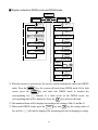
■ Display contents in DRIVE mode and PRGM mode
Power on
PRGM mode
PRGM
DRIVE
DRIVE mode *1
DSPL
DSPL
Frequency reference
value displayed
An-□ □ monitor/set
DSPL
DSPL
display monitor/set item
Bn-□ □ monitor/set
DSPL
*2
DSPL
Sn-□ □ monitor/set
Un-□ □ monitor
DSPL
DSPL
An-□ □ monitor/set
Cn-□ □ monitor/set
DSPL
Bn-□ □ monitor/set
*3
DSPL
+ RESET
Sn-□ □ monitor
DSPL
DSPL
Cn-□ □ monitor
*1 When the inverter is powered up, the inverter system immediately enters into DRIVE
mode. Press the
occurs, press the
PRGM
DRIVE
key, the system will switch into PRGM mode. If the fault
PRGM
DRIVE
key and enter into DRIVE mode to monitor the
corresponding Un-□□ contents. If a fault occurs in the DRIVE mode, the
corresponding fault will be displayed. Press the
RESET
key and reset the fault.
*2 The monitored items will be displayed according to the settings of Bn-12 and Bn-13.
*3 When in the DRIVE mode, press the
DSPL
key and
RESET
key, the setting values of
Sn- and Cn-□□ will only be displayed for monitoring but not for changing or setting.
2-3
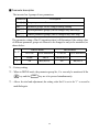
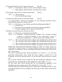
■ Parameter description
The inverter has 4 groups of user parameters:
Parameters
Description
An-□□
Frequency command
Bn-□□
Parameter groups can be changed during running
Sn-□□
System parameter groups (can be changes only after stop)
Cn-□□
Control parameter groups (can be changed only after stop)
The parameter setting of Sn-03 (operation status) will determine if the setting value
of different parameter groups are allowed to be changed or only to be monitored, as
shown below:
Sn-03
DRIVE mode
PRGM mode
To be set
To be monitored
To be set
To be monitored
0*1
An,Bn
Sn,Cn
An,Bn,Sn,Cn
-
1
An
Bn,(Sn,Cn) *2
An
Bn,Sn,Cn
*1 : Factory setting
*2 : When in DRIVE mode, the parameter group Sn-, Cn- can only be monitored if the
RESET
key and the
DSPL
key are to be pressed simultaneously.
*3 : After a few trial and adjustment, the setting value Sn-03 is set to be “1” so as not be
modified again.
2-4
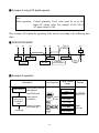
■ Example of using LCD digital operator
Note :
Before operation: Control parameter Cn-01 value must be set as the
input AC voltage value. For example, Cn-01=380 if
AC input voltage is 380.
This example will explain the operating of the inverter according to the following time
chart.
■ OPERATION MODE
(1)
(2)
(3)
(4)
(5)
(6)
FWD (7)
60 Hz
(8)
STOP
FWD JOG
POWER
OPERATION
ON
SET INPUT
VOLTAGE
FWD RUN
FREQUENCY
SETTING
REV RUN
FREQ REF.
VALUE CHANGED
REV
60Hz
■ Example of operation
Description
(1) When Power on
Select frequency reference
value displayed
Select PRGM mode
(2)
Input voltage
setting (e.g. AC
input voltage is
380V )
(continued)
Key Sequence
Select CONTROL
PARAMETER
Remark
Freq. Cmd.000.00Hz
TECO
An -01
Freq. Cmd. 1
PRGM
DRIVE
DSPL
EDIT
ENTER
Display Cn-01 setting
Input Voltage 380V
Digital Operator
Display
RESET
EDIT
ENTER
2-5
press 3
times
LED DRIVE
OFF
Cn -01Input Voltage
Cn-01 = 440.0V
Input Voltage
Cn-01 = 380.0V
Input Voltage
Entry Accepted
Display
for 0.5 sec
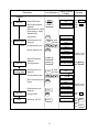
Description
Key Sequence Digital Operator
Display
Remark
(continued)
(3)
FWD JOG
Select DRIVE mode
PRGM
DRIVE
Freq. Cmd.000.00Hz
TECO
Select output frequency
displayed
DSPL
Freq. Cmd.0.00 Hz
O/P Freq. 0.00 Hz
LED DRIVE
ON
LED FWD
ON
Select direction of rotation
(When power on, initially
defaulted FWD)
Jog operation
(4)
Frequency setting
15 Hz
Select frequency cmd
displayed
O/P Freq. 6.00 Hz
Freq. Cmd. 6.00 Hz
JOG
DSPL
Change frequency cmd
RESET
Set new frequency cmd
ENTER
press
4 times
Freq. Cmd.000.00Hz
TECO
Freq. Cmd.015.00Hz
TECO
Freq. Cmd.015.00Hz
TECO
EDIT
Entry Accepted
(5)
(6)
FWD run
Frequency
command change
60 Hz
Select O/P frequency
displayed
DSPL
O/P Freq. 0.00 Hz
Freq. Cmd. 15.00 Hz
Running operation
RUN
O/P Freq. 15.00 Hz
Freq. Cmd. 15.00 Hz
Select frequency cmd
displayed
DSPL
Change reference value
RESET
Enter new frequency cmd
setting
EDIT
ENTER
press
4 times
(7)
REV RUN
(8)
STOP
Change to REV
Decrement to STOP
DSPL
FWD
REV
STOP
LED
ON
RUN
Freq. Cmd.015.00Hz
TECO
Freq. Cmd.060.00Hz
TECO
Freq. Cmd.060.00Hz
TECO
Entry Accepted
Select frequency cmd
displayed
Displayed for 0.5sec
Confirm the display.
Displayed for 0.5sec
Confirm the display.
O/P Freq. 60.00 Hz
Freq. Cmd. 60.00 Hz
O/P Freq. 60.00 Hz
Freq. Cmd. 60.00 Hz
LED REV
ON
O/P Freq. 0.00 Hz
Freq. Cmd. 60.00 Hz
LED
ON STOP
(Blinking
while
decel.) RUN
2-6
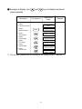
■ Example of display (use
items/contents)
Description
and
keys to display monitored
Key Sequence
Display
Frequency Command
Display
Moniter Contents *1
Digital Operator
Display
Remark
Freq. Cmd. 60.00Hz
TECO
Freq. Cmd. 60.00 Hz
O/P Freq. 60.00 Hz
DSPL
Display
Output Current
Freq. Cmd. 60.00 Hz
O/P I 12.5 A
Display
Output Voltage
Freq. Cmd. 60.00 Hz
O/P Volt. 220.0 V
Display
DC Voltage
Freq. Cmd. 60.00 Hz
DC Volt. 310.0 V
Display
Output Voltage
Freq. Cmd. 60.00 Hz
O/P Volt. 220.0 V
Display
Output Current
Freq. Cmd. 60.00 Hz
O/P I 12.5 A
*1. The monitor contents can be selected by the setting of Bn-12 and Bn-13
2-7
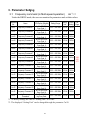
3. Parameter Setting
3.1
Frequency command (in Multi-speed operation)
An*1-□□
Under the DRIVE mode, the user can monitor the parameters and set their values.
Parameter
No.
Name
An-01
Frequency Command 1
An-02
Frequency Command 2
An-03
Frequency Command 3
An-04
Frequency Command 4
An-05
Frequency Command 5
An-06
Frequency Command 6
An-07
Frequency Command 7
An-08
Frequency Command 8
An-09
Frequency Command 9
An-10
Frequency Command 10
An-11
Frequency Command 11
An-12
Frequency Command 12
An-13
Frequency Command 13
An-14
Frequency Command 14
An-15
Frequency Command 15
An-16
Frequency Command 16
An-17
Jog Frequency
Command
LCD Display (English)
An-01= 000.00Hz
Freq. Cmd. 1
An-02= 000.00Hz
Freq. Cmd. 2
An-03= 000.00Hz
Freq. Cmd. 3
An-04= 000.00Hz
Freq. Cmd. 4
An-05= 000.00Hz
Freq. Cmd. 5
An-06= 000.00Hz
Freq. Cmd. 6
An-07= 000.00Hz
Freq. Cmd. 7
An-08= 000.00Hz
Freq. Cmd. 8
An-09= 000.00Hz
Freq. Cmd. 9
An-10= 000.00Hz
Freq. Cmd. 10
An-11= 000.00Hz
Freq. Cmd. 11
An-12= 000.00Hz
Freq. Cmd. 12
An-13= 000.00Hz
Freq. Cmd. 13
An-14= 000.00Hz
Freq. Cmd. 14
An-15= 000.00Hz
Freq. Cmd. 15
An-16= 000.00Hz
Freq. Cmd. 16
An-17= 000.00Hz
Jog Freq. Cmd.
Setting Range
Setting*2 Factory
Unit
Setting
0.00~400.00Hz 0.01Hz 0.00Hz
0.00~400.00Hz 0.01Hz 0.00Hz
0.00~400.00Hz 0.01Hz 0.00Hz
0.00~400.00Hz 0.01Hz 0.00Hz
0.00~400.00Hz 0.01Hz 0.00Hz
0.00~400.00Hz 0.01Hz 0.00Hz
0.00~400.00Hz 0.01Hz 0.00Hz
0.00~400.00Hz 0.01Hz 0.00Hz
0.00~400.00Hz 0.01Hz 0.00Hz
3-54
3-70
3-71
0.00~400.00Hz 0.01Hz 0.00Hz
0.00~400.00Hz 0.01Hz 0.00Hz
0.00~400.00Hz 0.01Hz 0.00Hz
0.00~400.00Hz 0.01Hz 0.00Hz
0.00~400.00Hz 0.01Hz 0.00Hz
0.00~400.00Hz 0.01Hz 0.00Hz
0.00~400.00Hz 0.01Hz 0.00Hz
0.00~400.00Hz 0.01Hz 6.00Hz
*1. At factory setting, the value of “Setting Unit” is 0.01Hz.
*2. The displayed “Setting Unit” can be changed through the parameter Cn-28.
3-1
Ref.
Page
3-56
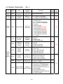
3.2 Parameters Groups Can Be Changed during Running Bn-□□
Under the DRIVE mode, the Parameter group can be monitored and set by the users.
Function
Acc/Dec
time
Parameter
No.
Name
Bn-01
Acceleration Time 1
Bn-02
Deceleration Time 1
Bn-03
Acceleration Time 2
Bn-04
Deceleration Time 2
Bn-05
Analog
Frequency
Bn-06
Bn-07
Bn-08
MultiFunction
Analog
Input
Torque
Boost
Bn-09
Bn-10
Analog Frequency
Cmd. Gain (Voltage)
Analog Frequency
Cmd. Bias (Voltage)
Analog Frequency Cmd
Gain. (Current)
Analog Frequency Cmd
Bias (Current)
Multi-Function Analog
Input Gain
Multi-Function Analog
Input Bias
Bn-11
Auto Torque Boost Gain
Bn-12
Monitor 1
Monitor
Bn-13
MultiFunction
Analog
Output
PID
Control
Bn-14
Bn-15
Monitor 2
Multi-Function Analog
Output AO1 Gain
Multi-Function Analog
Output AO2 Gain
Bn-16
PID Detection Gain
Bn-17
PID Proportional Gain
Bn-18
PID integral time
Bn-19
PID Differential Time
Bn-20
PID Bias
LCD display
(English)
Bn-01= 0010.0s
Acc. Time 1
Bn-02= 0010.0s
Dec. Time 1
Bn-03= 0010.0s
Acc. Time 2
Bn-04= 0010.0s
Dec. Time 2
Bn-05= 0100.0%
Voltage Cmd. Gain
Bn-06= 000.0%
Voltage Cmd. Bias
Bn-07= 0100.0%
Current Cmd. Gain
Bn-08= 000.0%
Current Cmd. Bias
Bn-09= 0100.0%
Multi_Fun. ~Gain
Bn-10= 000.0%
Multi_Fun. ~Bias
Bn-11= 0.5
Auto_Boost Gain
Bn-12= 01
Display: Freq.Cmd.
Bn-13= 02
Display: O/P Freq.
Bn-14= 1.00
~Output AO1 Gain
Bn-15= 1.00
~Output AO2 Gain
Bn-16= 01.00
PID Cmd. Gain
Bn-17= 01.00
PID P_gain
Bn-18= 10.00s
PID I_Time
Bn-19= 0.00s
PID D_Time
Bn-20= 0%
PID Bias
3-2
Setting range
Setting
Unit
Factory
Setting
0.0~6000.0s
0.1s
10.0s
0.0~6000.0s
0.1s
10.0s
0.0~6000.0s
0.1s
10.0s
0.0~6000.0s
0.1s
10.0s
0.0~1000.0%
0.10%
100.00%
-100.0%~100.0%
0.10%
0.00%
Ref.
Page
3-4
3-5
0.0~1000.0%
0.10%
100.00%
-100.0%~100.0%
0.10%
0.00%
0.0~1000.0%
0.10%
100.00%
3-5
-100.0%~100.0%
0.10%
0.00%
0.0~2.0
0.1
0.5
1~18
1
1
3-5
3-6
1~18
1
2
0.01~2.55
0.01
1
3-7
0.01~2.55
0.01
1
0.01~10.00
0.01
1
0.01~10.00
0.01
1
0.00~100.00s
0.01s
10.00s
0~1.00s
0.01s
0.00s
0~109%
1%
0%
3-7
Parameter
No.
Bn-21
Bn-22
Bn-23
Bn-24
Bn-25
Bn-26
Bn-27
Auto_Run
Time
Function
Bn-28
Bn-29
Bn-30
Bn-31
Bn-32
Bn-33
Bn-34
Bn-35
Bn-36
Timer
Function
Bn-37
Bn-38
Name
1st_Step Time Under
Auto_Run Mode
2nd_Step Time Under
Auto_Run Mode
3rd_Step Time Under
Auto_Run Mode
4th_Step Time Under
Auto_Run Mode
5th_Step Time Under
Auto_Run Mode
6th_Step Time Under
Auto_Run Mode
7th_Step Time Under
Auto_Run Mode
8th_Step Time Under
Auto_Run Mode
9th_Step Time Under
Auto_Run Mode
10th_Step Time Under
Auto_Run Mode
11th_Step Time Under
Auto_Run Mode
12th_Step Time Under
Auto_Run Mode
13th_Step Time Under
Auto_Run Mode
14th_Step Time Under
Auto_Run Mode
15th_Step Time Under
Auto_Run Mode
16th_Step Time Under
Auto_Run Mode
Timer Function
On_Delay Time
Timer Function
Off_Delay Time
Energy
Saving
Bn-39
Energy_Saving Gain
Monitor
Bn-40
Monitor 3
LCD display
(English)
Bn-21= 0000.0s
Time 1
Bn-22= 0000.0s
Time 2
Bn-23= 0000.0s
Time 3
Bn-24= 0000.0s
Time 4
Bn-25= 0000.0s
Time 5
Bn-26= 0000.0s
Time 6
Bn-27= 0000.0s
Time 7
Bn-28= 0000.0s
Time 8
Bn-29= 0000.0s
Time 9
Bn-30= 0000.0s
Time 10
Bn-31= 0000.0s
Time 11
Bn-32= 0000.0s
Time 12
Bn-33= 0000.0s
Time 13
Bn-34= 0000.0s
Time 14
Bn-35= 0000.0s
Time 15
Bn-36= 0000.0s
Time 16
Bn-37= 0000.0s
ON_delay Setting
Bn-38= 0000.0s
OFF_delay Setting
Bn-39= 100%
Eg.Saving Gain
Bn-40=00
Display : Set_Freq.
3-3
Setting range
Setting
Unit
Factory
Setting
0.0~6000.0s
0.1s
0.0s
0.0~6000.0s
0.1s
0.0s
0.0~6000.0s
0.1s
0.0s
0.0~6000.0s
0.1s
0.0s
0.0~6000.0s
0.1s
0.0s
0.0~6000.0s
0.1s
0.0s
0.0~6000.0s
0.1s
0.0s
0.0~6000.0s
0.1s
0.0s
0.0~6000.0s
0.1s
0.0s
0.0~6000.0s
0.1s
0.0s
0.0~6000.0s
0.1s
0.0s
0.0~6000.0s
0.1s
0.0s
0.0~6000.0s
0.1s
0.0s
0.0~6000.0s
0.1s
0.0s
0.0~6000.0s
0.1s
0.0s
0.0~6000.0s
0.1s
0.0s
0.0~6000.0s
0.1s
0.0s
Ref.
Page
3-70
3-71
3-9
0.0~6000.0s
0.1s
0.0s
50~150%
1%
100%
3-10
00~18
1
0
3-10
Parameter
No.
Bn-41
Pulse
Input
Bn-42
Bn-43
Bn-44
PID
Feedback
Display
Bn-45*1
Bn-46*1
LCD display
(English)
Bn-41=1440 Hz
Pulse Input Upper Limit
Pulse_Mul._Up_Bound
Bn-41=100.0 %
Pulse Input Gain
Pulse_Mul._Gain
Bn-41=000.0 %
Pulse Input Bias
Pulse_Mul._Bias
Bn-41=0.10 s
Pulse Input Delay Time
Pulse_Mul._Filter
PID Feedback Display
Bn-45= 0000
at 0%
PID Display at 0%
Name
PID Feedback Display
at 100%
Bn-46= 1000
PID Display at 0%
Setting range
Setting
Unit
Factory
Setting
1440~32000
1 Hz
1440
0.0~1000.0
0.10%
100
-100.0~100.0
0.1Hz
0
0.00~2.00
0.01s
0.1
1~9999*1
1*2
0
Ref.
Page
3-11
3-11
1~9999*1
1*2
1000
*1. These parameters are available for 74.03 and later software version only.
*2. The displayed “Setting Unit” and “Setting Range” can be changed through parameter Cn-28 and
Sn-70.
(1) Acceleration Time 1 (Bn-01)
(2) Deceleration Time 1 (Bn-02)
(3) Acceleration Time 2 (Bn-03)
(4) Deceleration Time 2 (Bn-04)
• Set individual Acceleration/Deceleration times
• Acceleration time: the time required to go from 0% to 100% of the maximum
output frequency
• Deceleration time: the time required to go from 100% to 0% of the maximum
output frequency
• If the acceleration/deceleration time sectors 1 and 2 are input via the multi-function
inputs terminal g~j, the acceleration/Deceleration can be switched between 2
sectors even in the running status.
Output frequency
Cn-02
Control circuit terminals 5 ~ 8
Open : select the 1st sector Acc./Dec. time
(Parameters Bn-01, Bn-02 set)
Close : select the 2nd sector ACC/DEC time
(Parameters Bn-03, Bn-04 set)
Bn-01
Bn-03
Bn-02
Time
Bn-04
Fig. 9. Acceleration and Deceleration time
Note :
1. To set the S-curve characteristics function, please refer to the description of Cn-41~Cn-44.
2. The S-curve characteristic times can be set respectively for beginning-accel. end-accel.,
beginning-decel., and end-decel. through the parameters setting of Cn-41~Cn-44.
3-4
(5) Analog Frequency Command Gain (Voltage) (Bn-05)
(6) Analog Frequency Command Bias (Voltage) (Bn-06)
(7) Analog Frequency Command Gain (Current) (Bn-07)
(8) Analog Frequency Command Bias (Current) (Bn-08)
(9) Multi-function Analog Input Gain
(Bn-09)
(10) Multi-function Analog Input Bias
(Bn-10)
• For every different analog frequency command (voltage or current) and multifunction analog inputs, their corresponding gain and bias should be specified
respectively.
command value
Max. output
frequency
gain
100
Max. output
frequency
bias
100
0V
(4 mA)
10V
(20 mA)
Input voltage
(Input current)
* ( ) If current
command is used
Fig. 10. Analog input gain and bias
(11) Auto Torque Boost Gain
(Bn-11)
• The inverter can increase the output torque to compensate the load increase
automatically through the auto torque boost function. Then the output voltage will
increase. As a result, the fault trip cases can be decreased. The energy efficiency is
also improved. In the case that the wiring distance between the inverter and the
motor is too long (e.g. more than 100m), the motor torque is a little short because of
voltage drop. Increase the value of Bn-11 gradually and make sure the current will
not increase too much. Normally, no adjustment is required.
output
voltage
100 %
torque
increase
torque
decrease
Base frequency
Fig. 11. Adjust the auto torque boost gain Bn-11 to increase the output torque.
• If the driven motor capacity is less than the inverter capacity (Max. applicable
motor capacity), raise the setting.
• If the motor generates excessive oscillation, lower the setting.
3-5
(12) Monitor 1 (Bn-12)
(13) Monitor 2 (Bn-13)
• In the DRIVE mode, 2 inverter input/output statuses can be monitored at the same
time. The specified items can be set through the setting of Bn-12 and Bn-13. For
more details, refer to Table 8.
• Example:
(1) Bn-12= 02 Display
O/P Freq.
15.00Hz
Bn-13= 01
Freq.Cmd. 15.00Hz
(2) Bn-12= 03 Display
Bn-13= 05
O/P I
DC Volt
21.0A
311V
(3) Bn-12= 11 Display
Bn-13= 12
I/P Term.
O/P Term.
00101010
00010010
Note : While monitoring, use the
or
key to show the next lower-row
displayed. But the setting of Bn-12 and Bn-13 does not change.
Table 8 Setting of Monitoring contents
Setting
Bn-12= 01
Bn-12= 02
Bn-12= 03
Bn-12= 04
Bn-12= 05
Bn-12= 06
Bn-12= 07
Bn-12= 08
Bn-12= 09
Bn-12= 10
Bn-12= 11
Bn-12= 12
Bn-12= 13
Bn-12= 14
Bn-12= 15
Bn-12= 16
Bn-12= 17
Bn-12= 18
Monitoring
contents
Freq.Cmd.
O/P Freq.
O/P I
O/P V
DC Volt
Term. VIN
Term. AIN
Term. AUX
~ Output(AO1)
~ Output(AO2)
I/P Term
O/P Term
Sp. FBK
Sp. Compen.
PID I/P
PID O/P(Un-16)
PID O/P(Un-17)
Motor Sp.
Setting
Bn-13= 01
Bn-13= 02
Bn-13= 03
Bn-13= 04
Bn-13= 05
Bn-13= 06
Bn-13= 07
Bn-13= 08
Bn-13= 09
Bn-13= 10
Bn-13= 11
Bn-13= 12
Bn-13= 13
Bn-13= 14
Bn-13= 15
Bn-13= 16
Bn-13= 17
Bn-13= 18
3-6
Monitoring
contents
Freq.Cmd.
O/P Freq.
O/P I
O/P V
DC Volt
Term. VIN
Term. AIN
Term. AUX
~ Output(AO1)
~ Output(AO1)
I/P Term
O/P Term
Sp. FBK
Sp. Compen.
PID I/P
PID O/P(Un-16)
PID O/P(Un-17)
Motor Sp.
(14) Multi-function Analog Output AO1 Gain (Bn-14)
(15) Multi-function Analog Output AO1 Gain (Bn-15)
• Multi-function analog output AO1 and AO2 can be set for their individual voltage
level respectively.
Multi-functional analog output AO1
(output contents depend on Sn-33)
10.0 V * Bn-14
Terminal
AO1
Multi-functional analog output AO2
( output contents depend on Sn-34)
10.0 V * Bn-15
Terminal
AO2
(16) PID Detection Gain
(Bn-16)
(17) PID Proportional Gain
(Bn-17)
(18) PID Integral Time
(Bn-18)
(19) PID Differential Time
(Bn-19)
(20) PID Bias
(Bn-20)
• The PID control function is a control system that matches a feedback value (i.e., a
detected value) to the set target value. Combining the proportional (P), integral (I)
and derivative (D) control make the control possible to achieve required response
with the constant setting and tuning procedure of proportional gain Bn-17, integral
time Bn-18 and derivative time Bn-19.
• See the appendix on page App.1 for “PID Parameter Setting”.
• Fig. 12 is a Block diagram of the inverter’s internal PID control.
• If both the target value and feedback value are set to 0, adjust the inverter output
frequency to zero.
Target
value
(multi-functional
analog input terminal
Aux when Sn-29 = 09)
Detected value
Bn-16
Ref. Com.terminal¡G
Vin 0 ~ 10 V (Sn-24 = 0)
Ain 4 ~ 20mA (Sn-24 = 1)
while PID enabled
Bias
Bn-20
(P)
Bn-17
(I)
Bn-18
(D)
Bn-19
integral
upper_limit
Upper_limit
(+/- 109 %)
1st order delay
constant
Cn-56
Freq. Com.
Cn-55
PID control O/P 1
(Un-16)
PID control input
(Un-15)
Fig. 12. Block diagram for PID control in inverter
(For the version before 30.17)
3-7
PID control O/P 2
(Un-17)
Deviation
Target value
Deviation
Detected value
(P)
Bn-18
(I)
Deviation
(D)
t
20 ms
Fig. 13. Response of PID control for step-shape (deviation) input
• Deviation = Target value-Detected value ×Bn-16.
• P’s control output = deviation ×Bn-17.
• I’s control output will increase with time and the output will be equal to the
deviation after time specified by parameter Bn-18
The parameter Cn-55 will prevent the calculated value of the integral control (with
the integral time Bn-18) in the PID control from exceeding the fixed amount.
Bn-19
D’s control output = difference × (
)
5 m sec
Note: The enable PID function, parameter Sn-64 must be set to 1
30.18 newly revised version inverter develops 8 PID control modes as following description:
0: Unavailable
1: (Positive characteristic) input of differential controller is balance of feedback value
and frequency value.
2: (Positive characteristic) input of differential controller is feedback value
3: (Positive characteristic) refers to frequency and PID control output. Input of
differential controller is balance of feedback value and frequency value.
4: (Positive characteristic) refers to frequency and PID control output. Input of
differential controller is feedback value
5: (Negative characteristic) input of differential controller is balance of feedback value
and frequency value.
6: (Negative characteristic) input of differential controller is feedback value
7: (Negative characteristic) refers to frequency and PID control output. Input of
differential controller is balance of feedback value and frequency value.
8: (Negative characteristic) refers to frequency and PID control output. Input of
differential controller is feedback value.
3-8
PID control
output 1 (Un-16)
+
+
Fig. 14. PID Control Block diagram (After Version 30.18)
(21) Time Setting in Auto_Run Mode (Bn-21~Bn-36)
• In Auto_Run mode, the time setting for individual step is described on “(Sn-44~60)
auto run mode selection and enable”.
(22) Timer ON_Delay Time (Bn-37)
(23) Timer OFF_Delay Time (Bn-38)
• The timer function is enabled when the timer function input setting (Sn-25~28=19)
and its timer function output setting (Sn-30~32=21) are set for the multi-function
input and output respectively.
• These inputs and outputs serve as general-purpose I/O. Setting ON/OFF delay time
(Bn-37/38) for the timer can prevent chattering of sensors, switches and so on.
• When the timer function input ON times is longer than the value set for Bn-37, the
timer function output turns ON.
• When the timer function input OFF time is longer than the value set for Bn-38, the
timer function output turns OFF. An example is shown below.
Timer function input
ON
ON
ON
Timer function output
Bn-37
ON
Bn-38
Bn-37
Fig. 15. An operation example of timer function
3-9
Bn-38
(24) Energy Saving Gain (Bn-39)
• Input the energy saving command while a light load causes the inverter output
voltage to be reduced and save energy. Set this value as a percentage of the V/F
pattern. The setting range is 50~150%. The factory setting is 100% and the energy
saving function is disabled. If the energy saving gain Bn-39 is not 100%, the energy
saving function is enabled.
• In energy saving mode (Bn-39≠100), the output voltage will automatically
decrease and be proportional to energy saving gain Bn-39. The Bn-39 setting
should not be small so that the motor will not stall.
• The energy saving function is disabled in the PID close-loop control and during
acceleration and deceleration.
Run command
V/f(Cn-01 & Cn-08) * Bn-39
Output voltage
0.1 sec
0.1 sec
Fig. 16. Time chart for energy-saving operation
(25) Monitor 3
(Bn-40)
• The parameter sets immediate display content as power on.
• When Bn-40 = 00, inverter power on, the first line will display frequency
command, while the second line will display characters “TECO” as following
diagram:
Freq . Cmd. : 15.00 Hz
TECO
• When Bn-40≠00, that is Bn-40=01~18, LCD will display the set monitor items
while inverter power on. The first line display content is determined by Bn-12. The
second line is determined by Bn-40 as following diagram:
Set Bn-12=01
Bn-40=02
Freq . Cmd. : 15.00 Hz
O / P Freq.: 00.00 Hz
• Bn-40=01~18 parameter description is same with Bn-12, Bn-13.
Please refer to Table 1, Monitor item set.
3-10
(26) Pulse Input setting (Bn-41~Bn-44)
• Setting Sn-05=3 before starting Pulse Input function. Please refer to Sn-05.
• Please refer to the following figure:
Upper Limit 100%
External Input
Frequency
Bn-44
Pulse Input
Delay
Bn-41
Pulse Input
Upper Limit
Command Value
Max. Output Freq.
Max. Output Freq.
×
Bn-42
100
×
Bn-43
100
Upper Limit 100%
0%
Command Value
100% Input Freq.
(27) PID Feedback Display at 0%
(Bn-45)
(28) PID Feedback Display at 100%
(Bn-46)
• These parameters are available for 74.03 and later software version only.
• The PID feedback can be input from control terminal VIN (0~10V) or AIN (420mA).
• The PID feedback value can be monitored by the monitoring parameter Un-34.
The display content can be set by Cn-28, Sn-70, Bn-45 and Bn-46.
Cn-28 sets the decimal point position of Un-34.
Sn-70 sets the unit of Un-34.
Bn-45 is the equivalent value displayed for 0% PID Feedback.
Bn-46 is the equivalent value displayed for 100% PID Feedback.
Target
Feedback
Signal
PID
Primary
Delay
Frequency
Command
Bn-16
Bn-45,46
PID Feedback Display
(Un-34)
• The decimal point position and the unit of Bn-45, Bn-46 can be set by Cn-28 and
Sn-70. It is necessary to set the value of Cn-28 and Sn-70 before Bn-45 and Bn-46
are set.
• Ex PID feedback signal is pressure signal. 0% for 5.0 PSI, and 100% for 100.0 PSI.
Set
Sn-70 = 3
(unit as PSI)
Cn-28 = 10000
(1 decimal)
Bn-45 = 005.0PSI
(display at 0%)
Bn-46 = 100.0PSI
(display at 100%)
3-11
3.3 Control Parameters Cn-□□
Function
V/F
Pattern
Setting
Motor
Parameter
Parameter
No.
Name
Cn-01
Input Voltage
Cn-02
Max. Output Frequency
Cn-03
Max. Output Voltage
Cn-04
Max. Voltage Frequency
Cn-05
Middle Output Frequency
Cn-06
Voltage At Middle Output
Frequency
Cn-07
Min Output Frequency
Cn-08
Voltage At Min. Output
Frequency
Cn-09
Motor Rated Current
Cn-10
No Load Current Of
Motor
Cn-11
Cn-12
Cn-13
Cn-14
DC Braking
Function
Cn-15
Cn-16
Cn-17
Frequency
Limit
Frequency
Jump
Cn-18
Cn-19
Rated Slip Of Motor
Line-To-Line Resistance
Of Motor
Torque Compensation Of
Core Loss
DC Injection Braking
Starting Frequency
DC Braking Current
DC Injection Braking
Time At Stop
DC Injection Braking
Time At Start
Frequency Command
Upper Bound
Frequency Command
Lower Bound
Cn-20
Frequency Jump Point 1
Cn-21
Frequency Jump Point 2
Cn-22
Frequency Jump Point 3
Cn-23
Jump Frequency Width
LCD display
(English)
Cn-01= 230.0V
Input Voltage
Cn-02= 060.0Hz
Max. O/P Freq.
Cn-03= 230.0Hz
Max. Voltage
Cn-04= 060.0Hz
Max. Volt Frequency
Cn-05= 003.0Hz
Middle O/P Freq.
Cn-06= 014.9V
Middle Voltage
Cn-07= 001.5Hz
Min O/P Freq.
Cn-08= 007.9V
Min. Voltage
Cn-09= 0003.3A
Motor Rated I
Cn-10= 30%
Motor No-Load I
Cn-11= 0.0%
Motor Rated Slip
Cn-12= 05.732Ω
Motor Line R
Cn-13= 0064W
Core Loss
Cn-14= 01.5Hz
C Braking Start F
Cn-15= 050%
DC Braking Current
Cn-16= 00.5s
DC Braking Stop Time
Cn-17= 00.0s
DC Braking Start Time
Cn-18= 100%
Freq.Cmd. Up Bound
Cn-19= 000%
Freq. Cmd. Low Bound
Cn-20= 000.0Hz
Freq. Jump 1
Cn-21= 000.0Hz
Freq. Jump 2
Cn-22= 000.0Hz
Freq. Jump 3
Cn-23= 01.0Hz
Freq. Jump Width
3-12
Setting range
Setting
Unit
Factory
Setting
Ref.
Page
150.0~255.0V*2
0.1V
230.0V*1
3-15
50.0~400.0Hz
0.1Hz
60.0Hz
0.1~255.0V*2
0.1V
230.0V*1
0.1~400.0Hz
0.1Hz
60.0Hz
0.1~400.0Hz
0.1Hz
3.0Hz
0.1~255.0V*2
0.1V
15.5V*1
0.1~400.0Hz
0.1Hz
1.5Hz
0.1~255.0V*2
0.1V
8.2V*1
*3
0.1A
3.3A*4
0~99%
1%
30%
3-15
3-15 3-16
0~9.9%
0.10%
0.00%
0~65.535Ω
0.001Ω
5.732*4
0~65535W
1W
64*4
0.1~10.0 Hz
0.1Hz
1.5Hz
0~100%
1%
50%
3-17
3-17
0.0~25.5s
0.1s
0.5s
0.0~25.5s
0.1s
0.0s
0~109%
1%
100%
3-18
0~109%
1%
0%
0.0~400.0Hz
0.1Hz
0.0Hz
0.0~400.0Hz
0.1Hz
0.0Hz
0.0~400.0Hz
0.1Hz
0.0Hz
0.0~25.5Hz
0.1Hz
1.0Hz
3-18
Function
Parameter
No.
Name
LCD display
(English)
Setting range
Setting
Unit
Factory
Setting
Ref.
Page
Retry
Function
Cn-24
Number of Auto Restart
Attempt
Cn-24= 00
Retry Times
0~10
1
0
3-19
Cn-25
Stall Prevention During
Acceleration
Cn-25= 170%
Acc. Stall
30~200%
1%
170%
Cn-26
Stall Prevention During
Running
Cn-26= 160%
Run Stall
30~200%
1%
160%
Comm.
Fault
detection
Cn-27
Communication Fault
Detection Time
Cn-27=01.0s
Comm. Flt Det. Time
0.1~25.5s
0.1s
1s
3-20
Display
Unit
Cn-28
LCD Digital Operator
Display Unit
Freq. Agree Detection
Level During Accel.
Freq. Agree Detection
Level During Decel.
Frequency Agree
Detection Width
Torque
Detection Level 1
Torque
Detection Time 1
0-39999
1
0
3-21
0.0~400.0Hz
0.1Hz
0.0Hz
0.0~400.0Hz
0.1Hz
0.0Hz
0.1~25.5Hz
0.1Hz
2.0Hz
0~200%
1%
160%
0.0~25.5s
0.1s
0.1s
1~6
1
6
0~200%
1%
150%
0.1~25.5s
0.1s
2.0s
Stall
Prevention
Cn-37
Min. Baseblock Time
Cn-38
V/F Curve in Speed
Search
Cn-28= 00000
Operator Disp. Unit
Cn-29= 000.0Hz
Acc. Freq. Det.Level
Cn-30= 000.0Hz
Dec. Freq. Det. Level
Cn-31= 02.0Hz
F Agree Det. Width
Cn-32= 160%
Tq. Det. Level 1
Cn-33= 00.1s
Tq. Det. Time 1
Cn-34= 6
Carry_Freq Setting
Cn-35= 150%
Sp-Search Level
Cn-36= 02.0s
Sp-Search Time
Cn-37= 0.5s
Min. B.B. Time
Cn-38= 100
Sp-search V/F Gain
Low
Voltage
Detection
Cn-39
Low Voltage Alarm
Detection Level
Slip Comp.
Cn-40
Cn-29
Frequency
Agree
Detection
Cn-30
Cn-31
Torque
Detection 1
Carrier
Frequency
Speed
Search
Control
S-curve
time
Cn-32
Cn-33
Cn-34
Carrier frequency setting
Cn-35
Speed Search Detection
Level
Cn-36
Speed Search Time
3-20
3-22
3-23
3-24
3-24
0.5~5.0s
0.1s
0.5s
10~100%
1%
100%
Cn-39= 200V
Low Volt. Det. Level
150~210V
1V
200V *1
3-26
Slip Compensation
Primary Delay Time
Cn-40= 02.0s
Slip Filter
0.0~25.5s
0.1s
2.0s
3-26
Cn-41
S-curve Characteristic
Time at Accel. Start
Cn-41= 0.0s
S1 Curve Time
0.0~1.0s
0.1s
0.0s
Cn-42
S-curve Characteristic
Time at Accel. End
Cn-42= 0.0s
S2 Curve Time
0.0~1.0s
0.1s
0.0s
Cn-43
S-curve Characteristic
Time at Decel. start
Cn-43= 0.0s
S3 Curve Time
0.0~1.0s
0.1s
0.0s
Cn-44
S-curve Characteristic
Time at Decel. end
Cn-44= 0.0s
S4 Curve Time
0.0~1.0s
0.1s
0.0s
3-13
3-26
Speed
feedback
control
Parameter
No.
Name
Cn-45
PG Parameter
Cn-46
Pole no. of Motor
Cn-47
ASR Proportional Gain 1
Cn-48
ASR Integral Gain 1
Cn-49
ASR Proportional Gain 2
Cn-50
ASR Integral Gain 2
Cn-51
ASR Upper Bound
Cn-52
ASR Lower Bound
Cn-53
Cn-54
PID
Control
Cn-55
Cn-56
Cn-57
Cn-58
Sensorless
Vector
Control
Cn-59
Cn-60
Cn-61
Torque
Detection 2
Cn-62*5
Cn-63*5
Excessive Speed
Deviation Detection Level
Overspeed Detection
Level
PID Integral Upper
Bound
PID Primary Delay Time
Constant
Motor Line-to-Line
Resistance (R1)
Motor Rotor Equivalent
Resistance (R2)
Motor Leakage
Inductance (Ls)
Motor Mutual
Inductance (Lm)
Slip Compensation Gain
Torque
Detection Level 2
Torque
Detection Time 2
LCD display
(English)
Cn-45= 0000.0
PG Parameter
Cn-46= 04P
Motor Pole
Cn-47= 0.00
ASR Gain 1
Cn-48= 01.0s
ASR Intgl. Time 1
Cn-49= 0.02
ASR Gain 2
Cn-50= 01.0s
ASR Intgl. Time 2
Cn-51= 05.0%
ASR Up Bound
Cn-52= 00.1%
ASR Low Bound
Cn-53= 10%
Sp.Deviat. Det.Level
Cn-54= 110%
Over Sp.Det. Level
Cn-55= 100%
PID I-Upper
Cn-56= 0.0s
PID Filter
Cn-57= 02.233Ω
Mtr LINE_R
Cn-58= 01.968Ω
Mtr ROTOR_R
Cn-59= 9.6mH
Mtr LEAKAGE_X
Cn-60= 149.7mH
Mtr MUTUAL_X
Cn-61= 1.00
SLIP GAIN
Cn-62= 160%
Tq. Det. Level 1
Cn-63= 00.1s
Tq. Det. Time 1
*1
*2
*3
*4
Setting range
Setting
Unit
Factory
Setting
0.0~3000.0P/R
0.1P/R
0.0P/R
2~32P
2P
4P
0.00~2.55
0.01
0
0.1~10.0S
0.1s
1.0s
0.00~2.55
0.01
0.02
0.1~10.0S
0.1s
1.0s
0.1~10.0%
0.10%
5.00%
0.1~10.0%
0.10%
0.10%
3-27
3-28
1~50%
1%
10%
1~120%
1%
110%
0~109%
1%
100%
3-28
0.0~2.5s
0.1s
0.0s
0.001~60.000Ω
0.001Ω
2.233Ω*4
0.001~60.000Ω
0.001Ω
1.968Ω*4
0.01~200.00mH
0.01mH
9.6mH *4
0.1~6553.5mH
0.1mH
149.7mH*4
0.00~2.55
0.01
1
0~200%
1%
160%
0.0~25.5s
0.1s
0.1s
3-28
3-29
3-23
These are for a 230V class inverter. Value(*1) for a 460V class inverter is double.
These are for a 230V class inverter. Value(*2) for a 460V class inverter is double.
The setting range is 10% ~200% of the inverter rated current.
The factory setting values will vary based upon the inverter capacity selection (Sn-01) value. In
this case, the setting is for 4-pole, 230V, 60Hz, 1Hp TECO standard induction motors.
*5. These parameters are available for 74.03 and later software version only.
3-14
Ref.
Page
(1) Input Voltage Setting
(Cn-01)
• Set inverter voltage to match power supply voltage at input side (e.g. : 200V/230V,
380V/415V/440V/460V)
(2) V/F Curve Parameter Settings
(Cn-02~Cn-08)
• The V/F curve can be set to either one of the preset curves (setting Sn-02=0~14)
or a customer user-set curve (setting Sn-02=15).
• Setting Cn-02~Cn-08 can be set by the user when Sn-02 has been set to “15”. The
user-defined V/F curve can be specified through the settings of Cn-02~Cn-08 as
shown in Fig. 17. The factory setting is straight line for the V/F curve. (Cn-05=Cn07, Cn-06 is not used) as shown below (230V/60Hz case).
Voltage
Voltage
Cn-03
220V
Cn-03
Cn-06
Cn-08
0
(Cn-08=Cn-06)
13
Cn-07 Cn-05 Cn-04 Cn-02
(Factory Setting)
0
Freq.
1.5 Hz
(Cn-07=Cn-05)
60 Hz Freq.
(Cn-04=Cn-02)
Fig. 17. User-defined V/F curve
• In low speed operation (<3Hz), a larger torque can be generated by increasing the
slope of V/F curve. However, the motor will be hot due to over-excitation. At the
same time the inverter will be more inclined to fault. Based upon the applied load,
properly adjust the V/F curve according to the magnitude of monitored current into
the motor.
• The four frequency settings must satisfy the following relationship, otherwise an
error message “V/F Curve Invalid” will display.
(a) Max. output freq.≧ Max. voltage freq. > Mid. Output freq. ≧ Min. output freq.
(Cn-02)
(Cn-04)
(Cn-05)
(b) Max. output volt.≧ Mid. output volt. > Min. output voltage
(Cn-03)
(Cn-06)
(Cn-08)
(Cn-07)
• If Mid. Output frequency (Cn-05) = Min. output frequency (Cn-07), the setting
(Cn-06) is not effective.
(3) Motor Rated Current (Cn-09)
• Electronic overload thermal reference current
• The factory setting depends upon the capacity type of inverter (Sn-01).
• The setting range is 10%~200% of the inverter rated output current.
• Set the rated current shown on the motor name plate if not using the TECO 4-pole
motor.
3-15
(4) Motor No-Load Current (Cn-10)
• This setting is used as a reference value for torque compensation function.
• The setting range is 0~99% of the inverter rated current Cn-09 (100%).
• The slip compensation is enabled when the output current is greater than motor noload current (Cn-10). The output frequency will shift from f1 to f2 (>f1) for the
positive change of load torque. (See Fig. 18)
Slip compensation =
Motor rated slip (Cn-11) ×(Output current – Motor no-load current(Cn-10))
Motor rated current (Cn-09) – Motor no-load current (Cn-10)
Load torque
f1
smaller load
f2
larger load
speed
Fig. 18. Output frequency with slip compensation.
(5) Motor Rated Slip
(Cn-11)
• This setting is used as a reference value for torque compensation function. See Fig.
17. The setting is 0.0~9.9% as a percentage of motor Max. voltage frequency (Cn04) as 100%.
• The setting is shown in Fig. 19 in the constant torque and constant output range. If
setting Cn-11 is zero, no slip compensation is used.
• There is no slip compensation in the cases when the frequency command is less
than the Min. output frequency or during regeneration.
Motor rated slip (Cn-11) =
Cn-02
Cn-04
Motor rated freq. (Hz) ×(Rated speed(RPM) – Motor No. of poles)
×100%
Max-voltage freq (Cn-04) ×120
Cn-11
Cn-11
Cn-04
Cn-02
Fig. 19. Slip compensation limit
3-16
(6) Motor Line-to-Line Resistance
(Cn-12)
(7) Motor Iron-Core Loss
(Cn-13)
• It is for torque compensation function. The default setting depends upon the
inverter capacity (Sn-01). Normally, the setting does not need to be altered. See
Table 10~11 on page 3-39.
(8) DC Injection Braking Starting Frequency
(Cn-14)
(9) DC Injection Braking Current
(Cn-15)
(10) DC Injection Braking Time at Stop
(Cn-16)
(11) DC Injection Braking Time at Start
(Cn-17)
• The DC injection braking function decelerates by applying a DC current to the
motor. This happens in the 2 cases:
a. DC injection braking time at start: It is effective for temporarily stopping and then
restarting, without regeneration, a motor coasting by inertia.
b. DC injection braking time at stop: It is used to prevent coasting by inertia when the
motor is not completely stopped by normal deceleration when there is a large load.
Lengthening the DC injection braking time (Cn-16) or increasing the DC injection
braking current (Cn-15) can shorten the stopping time.
• For the DC injection braking current (Cn-15), set the value for the current that is
output at the time of DC injection braking. DC injection braking current is set as a
percentage of inverter rated output current, with the inverter rated output current
taken as 100%.
• For the DC injection braking time at start (Cn-17), set the DC injection braking
operating time when the motor is started.
• For the DC injection braking starting frequency (Cn-14), set the frequency for
beginning DC injection braking for deceleration. If the excitation level is less than
the Min. output frequency (Cn-07), the DC injection braking will begin from Min.
output frequency.
• If the DC injection braking time at start (Cn-17) is 0.0, the motor starts from the
Min. output frequency and no DC injection braking are enabled.
• If the DC injection braking time at stop (Cn-16) is 0.0, no DC injection braking is
enabled. In this case, the inverter output will be blocked off when the output
frequency is less than the DC injection braking at start frequency (Cn-14).
Cn-07
Min. output frequency
Cn-14
DC injection braking
starting frequency
Cn-17
DC injection braking at start
Cn-16
DC injection braking at stop
Fig. 20. DC injection braking time chart
3-17
(12) Frequency Command Upper Bound
(Cn-18)
(13) Frequency Command Lower Bound
(Cn-19)
• The upper and lower bounds of the frequency command are set as a percentage of
the Max. output frequency (Cn-02 as 100%), in increments of 1%.
• The relationship Cn-18 > Cn-19 must be abided by. If not, an error message “Freq.
Limit Setting Error” may occur.
• When the frequency command is zero and a run command is input, the motor
operates at the frequency command lower bound (Cn-19). The motor will not
operate, however, if the lower limit is set lower than the Min. output frequency (Cn07).
Output frequency
100%
Cn-18
Cn-19
frequency command 100%
Fig. 21. Upper and lower bounds of the frequency command
(14)
(15)
(16)
(17)
Frequency Jump Point 1
Frequency Jump Point 2
Frequency Jump Point 3
Jump Frequency Width
(Cn-20)
(Cn-21)
(Cn-22)
(Cn-23)
• These settings allow the “jumping” of certain frequencies within the inverter’s
output frequency range so that the motor can operate without resonant oscillations
caused by some machine systems.
Output
frequency
Cn-20
Cn-23
Cn-21
Cn-22
Cn-23
Cn - 20 ≥ Cn - 21 ≥ Cn - 22
Cn-23
Set frequency command
Fig. 22. setting jump frequencies
3-18
• Operation is prohibited within the jump frequency range, but changes during
acceleration and deceleration are smooth with no jump. To disable this function, set
the jump frequency 1~3 (Cn-20~Cn-22) to 0.0Hz.
• For the jump frequency 1~3 (Cn-20~Cn-22), set the center frequency to be
jumped.
• Be sure to set the jump so that Cn-20 ≥ Cn-21 ≥ Cn-22. If not, a message “Jump
frequency setting error” is displayed. For Cn-23, set the jump frequency bandwidth.
If Cn-23 is set as 0.0Hz, the jump frequency function is disabled.
(18) Number of Auto Restart Attempt (Cn-24)
• The fault restart function will restart the inverter even when an internal fault occurs
during inverter operation. Use this function only when continuing operation is more
important than possibly damaging the inverter.
• The fault restart function is effective with the following faults. With other faults, the
protective operations will engage immediately without attempting to restart
operation.
• Over-current •Ground fault •Main circuit over-voltage
• The fault restart count will automatically increase upon the restart activated and
will be cleared in the following cases:
a. When the operation is normal for 10 minutes after a fault restart is performed.
b. When the fault-reset input is received after the protection operation has been
activated and the fault confirmed. (e.g., by pressing RESET or enable Fault reset
terminal e)
c. When the power is turned off and on again.
• When one of the multi-function output terminals (RA-RB-RC or R1A-R1B-R1C,
DO1, DO2 or R2A-R2C) is set to restart enabled, the output will be ON while the
fault restart function is in progress. See page 63 for the setting of (Sn-30~Sn-32).
3-19
(19) Stall Prevention Level During Acceleration
(Cn-25)
(20) Stall Prevention Level During Running
(Cn-26)
• A stall occurs if the rotor can not keep up with the rotating electromagnetic field in
the motor stator side when a large load is applied or a sudden acceleration or
deceleration is performed. In this case, the inverter should automatically adjust the
output frequency to prevent stall.
• The stall prevention function can be set independently for accelerating and running.
• Stall Prevention During Acceleration: See Fig.23. Stop acceleration if Cn-25 setting
is exceeded. Accelerate again when the current recovers.
• Stall Prevention During running : See Fig.24. Deceleration is started if the run stall
prevention level Cn-26 is exceeded, especially when an impact load is applied
suddenly. Accelerate again when the current level is lower than Cn-26.
Load
current
Load
current
Cn-25
Output
frequency
Cn-26
Time
Output
frequency
The output frequency is Time
controlled to prevent stalling
Time
Deceleration time
upon Bn-02, Bn-04
Time
The output frequency
decreases to prevent stalling
Fig. 23 Acceleration stall prevention
Fig. 24 Run stall prevention function
function
• Set the parameters Cn-25 and Cn-26 as a percentage of inverter rated current (100%
corresponds to inverter rated current).
• See page 3-48, 3-49 for stall prevention function selection.
(21) Communication Fault Detection Time (Cn-27)
• Please refer to “MODBUS/PROFIBUS Application Manual”.
3-20
(22) LCD Digital Operator Display Unit (Cn-28)
• It sets the units to be displayed for the frequency command and frequency
monitoring. and sets the decimal points of PID feedback display (Un-34), PID
feedback display at 0% and 100% (Bn-45, 46) as described below:
Table 9 LCD digital Operator Display unit
Setting / Reading Content
Cn-28
Frequency command/monitoring
PID Feedback
0
Units of 0.01 Hz
1
Units of 0.01%
Set in the units of r / min (0 to 39999).
Displayed as XXXX
r / min = 120 x frequency reference (Hz) / Unit specified by Sn-70
2 to 39
Cn-28
(Set the number of motor poles in Cn-28,
only even data is allowed)
40 to
39999
The position of decimal point is set by the
value of the 5th digit of Cn-20.
5th digit = 0: Displayed as XXXX
5th digit = 1: Displayed as XXX.X
5th digit = 2: Displayed as XX.XX
5th digit = 3: Displayed as X.XXX
The 1st digit to 4th digits of Cn-28 set the
value of 100% frequency.
y 5th digit = 0:
Displayed as XXXX
y 5th digit = 1:
Displayed as XXX.X
y 5th digit = 2:
Displayed as XX.XX
y 5th digit = 3:
displayed as X.XXX
The 1st digit to 4th
digits of Cn-28 are not
used.
Unit specified by Sn-70
• Example 1:
When the set value of 100% speed is 200.0, Cn-28 = 12000 is set.
60% speed is displayed as 120.0 at Cn-28 = 12000.
• Example 2:
When the set value of 100% speed is 65.00, Cn-28 = 26500 is set.
60% speed is displayed as 39.00 at Cn-28 = 26500.
3-21
(23) Frequency Agree Detection Level During Acceleration
(Cn-29)
(24) Frequency Agree Detection Level During Deceleration
(Cn-30)
(25) Frequency Agree Detection Width
(Cn-31)
• Frequency detection function: Set the multi-function output terminals (control
circuit terminals RA-RB-RC or R1A-R1B-R1C, DO1, DO2 or R2A-R2C) to output
the desired Frequency Agree signal, Setting Frequency Agree and Output
Frequency Detection level (through proper setting of Sn-30 ~ Sn-32).
• The time chart for Frequency Detection operation is described as follows:
Function
Frequency Detection Operation
freq. command
Frequency
Agree
FWD
output freq.
REV
freq. agree
signal output OFF
freq. command
Setting
Frequency
Agree
Cn-31
ON
Cn-31
Cn-31
Cn-29
FWD
output freq.
REV
agree freq.
signal output OFF ON
Description
• When output freq. is within freq.
command +/- freq. Detection width
(Cn-31), frequency agree output is
“ON”.
•Set Sn-30~Sn-32 to be “02” for the
setting of frequency agree output.
•After acceleration, the output freq.
reaches freq. Agree detection level
during acceleration (Cn-29) and within
freq. Agree detection width (Cn-31),
agreed freq. output is “ON”.
•Set Sn-30~Sn-32 to be “03”.
•During acceleration, the output freq. is
less than freq. agree detection level
output freq. Cn-31
Cn-31
during acceleration (Cn-29), output
Cn-29
Cn-30
FWD
freq. Detection 1 is “ON”.
Output
Cn-30 •During deceleration, the output freq. is
Cn-29
Frequency
REV
less than freq. agree detection level
Cn-31
Cn-31
Detection 1
during deceleration (Cn-30), output
output freq.
freq. Detection 1 is “ON”.
detection 1 signal ON OFF ON OFF
ON
•Set Sn-30~Sn-32 to be “04” for the
setting of output freq. detection.
•During acceleration, the output freq. is
larger than freq. Agree detection level
output freq. Cn-31
Cn-31
during acceleration (Cn-29), output
Cn-29
Cn-30
FWD
freq. detection 2 is “ON”.
Output
Cn-30 •During deceleration, the output freq. is
Cn-29
Frequency
REV
larger than freq. Agree detection level
Cn-31
Cn-31
Detection 2
during deceleration (Cn-30), output
output freq.
freq. detection 2 is “ON”.
detection 2 signal OFF ON OFF
ON
OFF
•Set Sn-30~Sn-32 to be “05” for the
setting of output freq. detection.
3-22
(26) Torque Detection Level 1
(Cn-32)
(27) Torque Detection Time 1
(Cn-33)
(28) Torque Detection Level 2
(Cn-62)
(29) Torque Detection Time 2
(Cn-63)
• Cn-62, 63 are available for 74.03 and later software version only.
• Both Overtorque Detection Function and Undertorque Detection Function are
included in Torque Detection Function. The Overtorque Detection Function detects
excessive mechanical load from an increase of output current. The Undertorque
Detection Function detects broken fan belt from a decrease of output current.
• An overtorque 1 condition is detected when the output current exceeds the Torque
Detection Level (Cn-32, Cn-62) for longer than the Torque Detection Time 1 (Cn33, Cn-63). See Fig.25-a below.
• An undertorque condition is detected when the output current is lower than the
Torque Detection Level (Cn-32, Cn-62) for longer than the Torque Detection Time
(Cn-33, Cn-63). See Fig.25-b below.
• When Torque Detection 1 is enabled through the setting Sn-12, be sure to set
Torque Detection Level 1 (Cn-32) and Torque Detection Time 1 (Cn-33).
• The Multi-Function Output Terminals (Control Circuit Terminals RA-RB-RC or
R1A-R1B-R1C, DO1, DO2 or R2A-R2C) can be set to indicate an overtorque
condition or an undertorque condition has been detected.
Motor
Current
Hysteresis
Width 5%
Cn-32
Overtorque
Detection Signal
ON
ON
Cn-33
Fig. 25-a.
Cn-33
Overtorque Detection Time Chart
Motor
Current
Hysteresis
Width 5%
Cn-32
ON
Undertorque
Detection Signal
Fig. 25-b.
ON
Cn-33
ON
Cn-33
Underorque Detection Time Chart
3-23
• Properly setting the value of Sn-12 (Torque Detection 1 Selection) and Sn-69
(Torque Detection 2 Selection) and will allow
a. Enable only during frequency agreement. Continue operation even after detection.
b. Enable only during frequency agreement. Stop operation after detection.
c. Enable at anytime. Continue operation even after detection.
d. Enable at anytime. Stop operation after detection.
(30) Carrier Frequency Setting
(Cn-34)
• Lower the carrier frequency can decrease the noise interference and leakage
current. Its setting is shown below.
Carrier frequency(kHz) = 2.5kHz* Cn-34 setting
Cn-34 =
1
2
(2.5 kHz)
3
4
5
6*
(15 kHz)
*factory setting
Carrier frequency
(louder)
Audio noise
(insensible)
• The output frequency does not need to be adjusted, except in the following cases.
a. If the wiring distance between the inverter and motor is long, lower the carrier
frequency as shown below to allow less leakage current.
Wring distance
Carrier frequency (Cn-34)
< 100ft.
<15kHz
100-165ft. 166-328ft.
<10kHz
<5KHz
> 329ft.
<2.5KHz
b. If there is great irregularity in speed or torque, lower the carrier frequency.
(31) Speed Search Detection Level
(Cn-35)
(32) Speed Search Time
(Cn-36)
(33) Min. Baseblock Time
(Cn-37)
(34) Speed Search V/F Curve
(Cn-38)
• The speed search function will search the speed of a frequency coasting motor from
the frequency command or max. frequency downward. And it will restart up
smoothly from that frequency or max. frequency. It is effective in situations such as
switching from a commercial power supply to an inverter without tripping
occurred.
• The timing of speed search function as shown below :
3-24
<0.5 sec
FWD(or REV) run command
Speed search command
Max output frequency
(or running frequency
while the speed search
is being performed)
Synchronous speed dectection
Output frequency
Min baseblock time
voltage at speech search
retuen to voltage at
normal operation
ouput voltage
speed search operation
Fig. 26. Speed search timing chart
• The speed search command can be set through the multi-function contact input
terminal g ~ j (By setting the parameters Sn-25 ~ Sn-28).
If Sn-25 ~ Sn-28= 21 : Speed search is performed from Max. output frequency
and motor is coasting freely.
If Sn-25 ~ Sn-28= 22 : Speed search starts from the frequency command when the
speed search command is enabled.
• After the inverter output is blocked, the user should input speed search command
then enable run operation, the inverter will begin to search the motor speed after the
min. baseblock time Cn-37.
• Speed search operation, if the inverter output current is less than Cn-35, the inverter
will take the output frequency as the real frequency at that time. From those values
of real frequency, the inverter will accelerate or decelerate to the set frequency
according to the acceleration or deceleration time.
• While the speed search command is being performed, the user can slightly decrease
the setting of V/F curve (Cn-38) in order to prevent the OC protection function
enabled. Normally, the V/F curve need not be changed. (As below)
• Speed search operating V/F curve = Cn-38 * (normal operating V/F curve )
Note : 1. The speed search operation will be disabled if the speed search command is
enacted from the Max. frequency and the setting frequency. (I.e., Sn-25=20, Sn26=21 and multi-function input terminals g, h is used at the same time).
2. Make sure that the FWD/REV command must be performed after or at the
3-25
same time with the speed search command. A typical operation sequence is
shown below.
Ry1
Ry1
Ry2
Speed search command
RWD/REV run command
3. When the speed search and DC injection braking are set, set the Min.
baseblock time (Cn-37). For the Min. baseblock time, set the time long
enough to allow the motor’s residual voltage to dissipate. If an overcurrent is
detected when starting a speed search or DC injection braking, raise the
setting Cn-37 to prevent a fault from occurring. As a result, the Cn-37 setting
cannot be set too small.
(35) Low Voltage Alarm Detection Level (Cn-39)
• In most cases, the default setting Cn-39 need not be changed. If an external AC
reactor is used, decrease the low voltage alarm detection level by adjusting Cn-39
setting smaller. Be sure to set a main-circuit DC voltage so that a main circuit
undervoltage is detected.
(36) Slip Compensation Primary Delay Time
(Cn-40)
• In most cases, the setting Cn-40 need not be changed. If the motor speed is not
stable, increase the Cn-40 setting. If the speed response is slow, decrease the setting
of Cn-40.
(37) S-curve Characteristic Time at Acceleration Start (Cn-41)
(38) S-curve Characteristic Time at Acceleration End (Cn-42)
(39) S-curve Characteristic Time at Deceleration Start (Cn-43)
(40) S-curve Characteristic Time at Deceleration End (Cn-44)
• Using the S-curve characteristic function for acceleration and deceleration can
reduce shock to the machinery when stopping and starting. With the inverter, Scurve characteristic time can be set respectively for beginning acceleration, ending
acceleration, beginning deceleration and ending deceleration. The relation between
these parameters is shown in Fig. 27.
3-26
Run
command
ON
Output
frequency
OFF
S3
S2
S1
Cn-42
Cn-43
Cn-41
S4
Cn-44 Time
Fig. 27. S curve
• After the S-curve time is set, the final acceleration and deceleration time will be as
follows:
(Cn-41) + (Cn-42)
2
(Cn-43) + (Cn-44)
• Dec. time = selected Dec. Time 1 (or 2) +
2
• Acc. time = selected Acc. Time 1 (or 2) +
(41) PG Parameter
(Cn-45)
• The parameter is set in the unit of pulse/revolution. The factory setting is 0.1 P/R.
(42) Pole Number of Motor (Cn-46)
• Cn-45 and Cn-46 must meet the following relationship:
2 * Cn-45 * Cn-02
< 32767
Cn-46
• If not, an error message “Input Error” will be displayed
(43) ASR Proportion Gain 1 (Cn-47)
(44) ASR Integral Gain 1
(Cn-48)
• Set the proportion gain and integral time of the speed control (ASR)
(45) ASR Proportion Gain 2 (Cn-49)
(46) ASR Integral Gain 2
(Cn-50)
• Use these constants to set different proportional gain and integral time settings for
high-speed operation.
3-27
Proportional gain
Integral time
Cn-49
Cn-50
Cn-47
0%
100 %
Output
frequency
Cn-48
0%
100 %
Output
frequency
Fig. 28.
(47) ASR Upper Bound
(Cn-51)
(48) ASR Lower Bound
(Cn-52)
• These settings of Cn-51 and Cn-52 will limit the ASR range.
(49) Excessive Speed Deviation Detection Level (Cn-53)
• This parameter set the level of detecting PG speed deviation. The value of Cn-02 is
referred as 100%, the default unit setting is 1%.
(50) Overspeed Detection Level
(Cn-54)
• Set this parameter for detecting overspeed. The value of Cn-02 is referred as 100%,
the default unit setting is 1%. Please refer to the setting of Sn-43.
(51) PID Integral Upper Bound
(Cn-55)
(52) PID Primary Delay Time Constant (Cn-56)
• Please refer to Fig. 14 “Block diagram for PID control in inverter”
• The parameter Cn-55 prevents the calculated value of the integral control of PID
from exceeding the fixed amount. The value is limited within 0-109% of Max.
output frequency (100%). Increase Cn-55 will improve the integral control. If
hunting cannot be reduced by decreasing the Bn-18 or increasing Cn-56, Cn-55 has
to decrease. If the setting of Cn-55 is too small, the output may not match the target
setting.
• The parameter Cn-56 is the low-pass filter setting for PID control output. If the
viscous friction of the mechanical system is high, or if the rigidity is low, causing
the mechanical system to oscillate, increase the setting Cn-56 so that it is higher
than the oscillation period. It will decrease the responsiveness, but it will prevent
the oscillation.
(53) Motor Line-to-Line Resistance R1 (Cn-57)
• Set the motor’s terminal resistance (including the motor external cable resistance)
in Ω unit.
• The default setting depends upon the type of inverter (but do not include the motor
external motor cable resistance).
3-28
• This value will be automatically set during autotuning. See “Motor parameter
autotuning selection” on page 3-73.
• Increase the setting when the generating torque is not large enough at low speed.
• Decrease the setting when the generating torque is extremely high and cause
overcurrent trip at low speed.
(54) Motor Rotor Equivalent Resistance R2 (Cn-58)
• Set the motor’s rotor Y-equivalent model resistance in unit.
• The default setting depends upon the type of inverter. Normally this value isn’t
shown on the motor’s nameplate, so it might be necessary to contact motor
manufactor.
• This value will be automatically set during autotuning. See “Motor parameter
autotuning selection” on page 3-73.
(55) Motor Leakage Inductance Ls (Cn-59)
• Set the motor’s rotor Y-equivalent model leakage inductance in mH unit.
• The default setting depends upon the type of inverter.
• This value will be automatically set during autotuning. See “Motor parameter
autotuning selection” on page 3-73.
(56) Motor Mutual Inductance Lm (Cn-60)
• Set the motor Y-equivalent model mutual inductance in mH unit.
• The default setting depends upon the type of inverter.
• This value will be automatically set during autotuning. See “Motor parameter
autotuning selection” on page 3-73.
Note: The Induction Motor Y-equivalent model
R1
Ls
Iq
Id
Lm
R2
s
s : slip
(57) Slip Compensation Gain
(Cn-61)
• The parameter Cn-61 improves speed accuracy while operating with a load.
• Usually, the setting Cn-61 need not be changed. Adjust the setting if the speed
accuracy is needed to improve.
• When actual speed is low, increase the set value.
• When actual speed is high, decrease the set value.
3-29
3.4 System Parameters
Function
Parameter
No.
Capacity
Setting
Sn-01
V/F Curve
Sn-02
Operator
Status
Sn-03
Sn-04
Sn-05
Sn-06
Operation
Control
Mode
Selection
Sn-07
Sn-08
Sn-09
Sn-□□
Name
LCD display
(English)
Inverter Capacity
Selection
V/F Curve
Selection
Sn-01= 01
220V 1HP
Sn-02= 01
V/F curve
Description
Inverter capacity selection
0~14 : 15 fixed V/F curve pattern
15 : arbitrary V/F pattern selection
0 : An-□□, Bn-□□, Cn-□□, Sn-□□ setting
& reading enabled
1 : An-□□, setting & reading enabled
Bn-□□,Cn-□□,Sn-□□ reading only
2~5 : reserved
6 : clear fault message
Sn-03= 00
7 : 2-wire initialization (230V/460V)
Operator Display
Setting Valid
8 : 3-wire initialization (230V/460V)
9 : 2-wire initialization (200V/415V)
10 : 3-wire initialization (200V/415V)
11 : 2-wire initialization (200V/380V)
12 : 3-wire initialization (200V/380V)
13~15 : reserved
Run source
Sn-04= 0
Run Source
0 : Operator
Run source
1 : Control terminal
Selection
Operator
2 : RS-485 communication
Frequency Command
Frequency
Sn-05= 0
0 : Operator
Command
Ref. Cmd.
1 : Control circuit terminal
Selection
Operator
2 : RS-485 communication
0 : Deceleration to Stop
Stopping
1 : Coast to Stop
Sn-06= 0
2 : Whole_range braking stop
Method
Dec. Stop
3 : Coast to Stop with Timer
Selection
(restart after time Bn-02)
If operation command from control terminal
Priority of
Sn-07= 0
or RS-485 communication port
Stopping
Stop Key Valid 0 : operator stop key effective
1 : operator stop key not effective
Prohibition of
Sn-08= 0
0 : reverse run enabled
REV Run
Allow Reverse 1 : reverse run disabled
0 : Reference frequency is changed
through the key ”UP/DOWN” pressing,
later followed by key “EDIT/ENTER”
Output Frequency
Sn-09= 0
pressing, and then this output freq. will
Up/Down Function Inhibit UP/DOWN
be acknowledged.
1 : reference frequency will be
acknowledged immediately after the key
”UP/DOWN” pressing.
3-30
Factory
Setting
Ref.
Page
*1
3-39
3-40
3-43
0
0
3-43
0
0
0
3-45
0
Function
Parameter
No.
Name
Sn-10
Frequency
Command
Characteristics
Selection
LCD display
(English)
Description
Sn-10= 0
Ref. Cmd. Fwd.
Char.
Sn-11
Scanning Times at
Sn-11= 0
Input Terminal
Scan Time 5 ms
Sn-12
Torque Detection
1 Selection
Sn-12= 0
Tq.Detect Invalid
Output Voltage
Limit Selection
Sn-13= 0
V Limit Invalid
Operation
Control
Mode
Selection
Sn-13
Protection
Characteristic.
selection
Sn-14
Sn-15
Stall Prevention
During Acc.
Function
Selection
Stall Prevention
During Dec.
Function
Selection
0 : Reference command has forward
characteristics
(0~10V or 4~20mA/0~100%
1 : Reference command has reverse
characteristics
(10~0V or 20~4mA/0~100%)
0 : scan and confirm once per 5 ms
1 : continuously scan and confirm twice per
10 ms
Option 5-8 are available for 74.03 and later
software version only.
0 : Torque detection function 1 is not
effective.
1 : Overtorque is detected only at
frequency agree. Continue operation
after detection.
2 : Overtorque is detected only at
frequency agree. Stop operation after
detection.
3 : Overtorque is detected during running
(Accel.,Decel. included). Continue
operation after detection.
4 : Overtorque is detected during running
(Accel., Decel included). Stop operation
after detection.
5 : Undertorque is detected only at
frequency agree. Continue operation
after detection.
6 : Undertorque is detected only at
frequency agree. Stop operation after
detection.
7 : Undertorque is detected during running
(Accel.,Decel. included). Continue
operation after detection.
8 : Overtorque is detected during running
(Accel., Decel included). Stop operation
after detection.
0 : V/F output voltage is limited
1 : V/F output voltage is not limited
Factory
Setting
0
3-46
0
0
3-47
0
Sn-14= 1
Acc. Stall Valid
0 : invalid (Too much a torque may cause
the stall)
1 : valid (stop acceleration if current
exceeds Cn-25 setting)
1
Sn-15= 1
Dec. Stall Valid
0 : invalid (installed with external brake
unit)
1 : valid (no external brake unit used)
1
3-31
Ref.
Page
3-48
Function
Protection
Characteristic.
selection
Parameter
No.
LCD display
(English)
Sn-16
Stall Prevention
During Running
Function Selection
Sn-16= 1
Run Stall Valid
Sn-17
Fault Retry
Setting
Sn-17= 0
Retry No O/P
Sn-18
Operation
Selection At
Power Loss
Sn-19
Sn-20
Sn-21
Sn-22
Protection
Characteristic.
Selection
Name
Sn-23
Sn-24
Description
0 : invalid
1 : valid –Deceleration time1 for stall
prevention during running (no external
brake unit used)
2 : valid –Deceleration time2 for stall
prevention during running (no external
brake unit used)
0 : Do not output fault retry.
(The fault contact does not operate.)
1 : Output fault retry.
(The fault contact operates.)
Sn-18= 0
0 : stop running
PwrL_to_ON Stop
1 : continue to run
O/P
(analog) Speed reference is 0 during
Zero Speed
running on, the braking function selection
Sn-19= 0
Braking Operation
Z_braking Invalid 0 : invalid
Selection
1 : valid
External Fault
Sn-20= 0
0 : A-contact (normally open input)
Contact e
Term.3 NO_Cont. 1 : B-contact (normally close input)
Contact Selection
External Fault
Sn-21= 0
0 : detect all time
Contact e
Detection
All Time Ext. Fault 1 : detect only during operation
Selection
0 : dec. to stop (upon dec. time1 Bn-02)
External Fault
Sn-22= 1
1 : coast (free run) to stop
Operation
Ext. Fault Free run 2 : dec. to stop (upon dec. time1 Bn-04)
Selection
3 : continue operating
Electronically motor overload protection
selection
0 : electronically motor overload protection
invalid
1 : standard motor cold start overload
Motor Overload
Sn-23= 1
protection characteristics
Protection
Cold Start Over
2 : standard motor hot start overload
Selection
Load
protection characteristics
3 : special motor cold start overload
protection characteristics
4 : special motor hot start overload
protection characteristics
Frequency command characteristics
Frequency
selection at external analog input terminal
0 : voltage signal 0~10V (VIN)
Command
Sn-24= 0
1 : current signal 4~20mA (AIN)
Characteristics
~ Cmd. VIN
Selection at
2 : addition of voltage signal 0~10V and
current signal 4~20 mA (VIN+AIN)
External Analog
3 : subtraction of current signal 4~20mA
Input Terminal
and voltage signal 0~10V (VIN-AIN)
3-32
Factory
Setting
Ref.
Page
1
0
3-49
0
0
0
0
1
3-50
1
0
3-51
Function
Parameter
No.
Sn-25
Multifunction
Input
Contact
Selection
Sn-26
Sn-27
Sn-28
Multifunction
Analog
Input
Selection
Sn-29
Sn-30
Multifunction
Digital
Output
Selection
Sn-31
Sn-32
Sn-33
Multifunction
Analog
Output
Selection
Sn-34
Name
LCD display
(English)
Sn-25= 02
Multi-Fun.
Command1
Sn-26= 03
Multi-Fun.
Command2
Description
Multi-Function
Input Terminal g
Function Selection
Multi-Function
Input Terminal h
Function Selection
Multi-Function
Sn-27= 06
Input Terminal i
Jog Command
Function Selection
Multi-Function
Sn-28= 07
Input Terminal j
Acc. & Dec Switch
Function Selection
Multi-Function
Analog Input
(AUX) Function
Selection
Multi-Function
Output Terminal
(RA-RB-RC)
Function Selection
Multi-Function
Output Terminal
(DO1) Function
Selection
Multi-Function
Output Terminal
(DO2) Function
Selection
Multi-Function
Analog Output
(AO1) Function
Selection
Multi-Function
Analog Output
(AO2) Function
Selection
Factory
Setting
00~25
The factory setting is multi-function
command1
02
01~26
The factory setting is multi-function
command2
03
3-51
The factory setting is jog
02~27
command
03~29
The factory setting is Acc. & Dec.
Interrupt
06
07
Multi-function analog input
terminal (AUX) as Auxiliary
00~16
frequency command. (factory
setting)
00
Sn-30= 13
Fault
Terminal (RA-RB-RC or R1A-R1B00~25 R1C) as fault output (factory
setting)
13
Sn-31= 00
Running
Terminal (DO1-DOG) as digital
00~25 output during running (factory
setting).
00
Sn-32= 01
Zero Speed
Terminal (DO2-DOG or R2A-R2C)
00~25 as digital output at zero speed
(factory setting)
01
Sn-29= 00
Auxiliary Freq.
Cmd.
Sn-33= 00
Term. AO1 Freq.
Cmd.
Sn-34= 01
Term. AO2 O/P
Freq.
Ref.
Page
0 : Freq. Cmd. (10.V/MAX frequency
command, Cn-02)
1 : Output frequency (10.V/MAX. output
frequency)
2 : Output current (10.V/input rated current)
3 : Output voltage (10.V/input voltage, Cn01)
4 : DC voltage
(10.V/400.V or 10.V/800.V)
5 : External analog input command
VIN (0.~10.V/0.~10.V)
6 : External analog input command AIN
(0.~10.V/4.~20.mA)
7 : Multi-function analog input (AUX)
(10.V/10.V)
8 : PID control input
9 : PID control output1
10:PID control output2
11:Communication Control
3-33
3-60
3-63
00
3-67
01
Sn-35
Pulse Output
Multiplier
Selection
Sn-35= 1
Pulse Mul. 6
When multi-function output terminal
(DO1,DO2) is set as pulse signal output
0:1F 1:6F 2:10F 3:12F 4:36F
3-34
1
3-67
Function
RS-485
Communication
Function
LCD display
(English)
Sn-36= 01
Inverter Address
Factory
Setting
Parameter
No.
Name
Sn-36
Inverter Address
Sn-37
RS-485 Comm.
Baud Rate Setting
Sn-37= 1
Baud rate 2400
Sn-38
RS-485 Comm.
Transmission
Parity Setting
Sn-38= 0
Reversed Bit
Sn-39
RS-485 Comm.
Fault Stop
Selection
Sn-39= 0
1st. Dec. stop
Sn-40
PG Speed Control
Function
Sn-40= 0
PG Invalid
Sn-41
Operation
Selection At PG
Open Circuit
Sn-41= 0
1st. Dec. Stop
0 : deceleration to stop (Bn-02)
1 : coast to stop
2 : deceleration to stop (Bn-04)
3 : continue to run
0
Sn-42
Operation
Selection
At PG Large
Speed Deviation
Sn-42= 0
1st. Dec Stop
0 : deceleration to stop (Bn-02)
1 : coast to stop
2 : deceleration to stop (Bn-04)
3 : continue to run
0
Sn-43
Operation
Selection
At PG Overspeed
Detection
Deviation
Sn-43= 0
1st. Dec. Stop
0 : deceleration to stop (Bn-02)
1 : coast to stop
2 : deceleration to stop (Bn-04)
3 : continue to run
0
PG Speed
Control
Description
Inverter address can be set as 1~31
01
0 : 1200 bps
1 : 2400 bps
2 : 4800 bps
3 : 9600 bps
1
0 : no parity
1 : even parity
2 : odd parity
0
0 : deceleration to stop (Bn-02)
1 : coast to stop
2 : deceleration to stop (Bn-04)
3 : continue to run
0 : without speed control
1 : with speed control
2 : with speed control but no integration
control during Acc/Dec.
3 : with speed control and integration
control during Acc/Dec.
3-35
Ref.
Page
3-68
0
0
3-69
Function
Parameter
No.
Sn-44
Auto_Run
Mode
Sn-45
Sn-46
Sn-47
Sn-48
Sn-49
Sn-50
Name
Operation Mode
Selection During
Auto_Run
Auto_Run Mode
Operation
Selection1
Auto_Run Mode
Operation
Selection2
Auto_Run Mode
Operation
Selection3
Auto_Run Mode
Operation
Selection4
Auto_Run Mode
Operation
Selection5
Auto_Run Mode
Operation
Selection6
LCD display
(English)
Description
0 : Auto_Run mode not effective
1 : Auto_Run mode for one single cycle.
(continuing running from the unfinished
step if restarting)
2 : Auto_Run mode be performed
periodically (continuing running from the
unfinished step if restarting)
3 : Auto_Run mode for one single cycle,
then hold the speed of final step to run.
Sn-44= 0
(continuing running from the unfinished
Auto_Run Invalid
step if restarting)
4 : Auto_Run mode for one single cycle.
(starting a new cycle if restarting)
5 : Auto_Run mode be performed
periodically (starting a new cycle if
restarting)
6 : Auto_Run mode for one single cycle,
then hold the speed of final step to run.
(starting a new cycle if restarting)
Factory
Setting
0
3-70
Sn-45= 0
Auto_Run Stop
0
Sn-46= 0
Auto_Run Stop
0
Sn-47= 0
Auto_Run Stop
Sn-48= 0
Auto_Run Stop
0 : stop (Bn-02)
1 : forward
2 : reverse
0
0
Sn-49= 0
Auto_Run Stop
0
Sn-50= 0
Auto_Run Stop
0
3-36
Ref.
Page
Function
Parameter
No.
Sn-51
Sn-52
Sn-53
Sn-54
Sn-55
Auto_Run
Mode
Sn-56
Sn-57
Sn-58
Sn-59
Sn-60
Sn-61
Sn-62
Parameter Copy
Sn-64
PID Function
Sn-66
Sn-67
LCD display
(English)
Description
Auto_Run Mode
Sn-51= 0
Operation
Auto_Run Stop
Selection7
Auto_Run Mode
Sn-52= 0
Operation
Auto_Run Stop
Selection8
Auto_Run Mode
Sn-53= 0
Operation
Auto_Run Stop
Selection9
Auto_Run Mode
Sn-54= 0
Operation
Auto_Run Stop
Selection10
Auto_Run Mode
Sn-55= 0
Operation
Auto_Run Stop
Selection11
Auto_Run Mode
Sn-56= 0
Operation
Auto_Run Stop
Selection12
Auto_Run Mode
Sn-57= 0
Operation
Auto_Run Stop
Selection13
Auto_Run Mode
Sn-58= 0
Operation
Auto_Run Stop
Selection14
Auto_Run Mode
Sn-59= 0
Operation
Auto_Run Stop
Selection15
Auto_Run Mode
Sn-60= 0
Operation
Auto_Run Stop
Selection16
Applied Torque
Sn-61= 0
Mode
Const. Tq. Load
Language
Sn-62= 0
Selection
Language: English
Sn-63
Sn-65
*2
Sensorless
Vector
Control
Name
Sn-63=0
Not Load
Sn-64=0
PID Invalid
Sn-65=0
Protect Invalid
Brake Resistor
Protection
Motor Parameters
Sn-66=0
Autotuning
AUTO TUNE SEL
Selection
Sn-67=0
Control Mode
CNTRL MODE
Selection
SEL
Factory
Setting
Ref.
Page
0
0
0
0
0 : stop (Bn-02)
1 : forward
2 : reverse
0
3-70
0
0
0
0
0
0 : constant torque
1 : variable(quadratic) torque
0 : English
1 : Traditional Chinese
0 : not loaded (copied)
1 : upload from digital operator to inverter
2 : download from inverter to digital
operator
3 : inspect the EEPROM of digital operator
4 : inspect the EEPROM of inverter
0 : PID invalid
1 : PID valid
0 : Braking resistor protection invalid
1 : Braking resistor protection valid
0 : Autotuning invalid
1 : Autotuning valid
0 : V/F control mode (include V/F control
with pulse generator feedback)
1 : Sensorless Vector Control Mode
3-37
0
0
3-72
0
0
3-73
0
0
3-73
0
Function
Parameter
No.
Name
LCD display
(English)
Description
Factory
Setting
Ref.
Page
0
3-73
0
3-47
The very parameter is available for 30.15
and later version
–––1: Output phase lose protection
function valid
–––0: Output phase lose protection
function invalid
––1–: Reserved
––0–: Reserved
Sn-68
Operation
Control
Mode
Selection
Sn-69*3
Control selection
Torque Detection
2 Selection
Sn-68=0000
Control selection
(Bit3 function is available for 30.16 and
later version)
–1––: ±10V analog voltage input function is
valid
–0––: ±10V analog voltage input function is
invalid
1–––: Frequency Up/Down hold function
valid
0–––: Frequency Up/Down hold function
invalid
* only 4P101C01301 control base board
supports input of ±10V analog voltage.
0 : Torque detection function 2 is not
effective.
1 : Overtorque is detected only at
frequency agree. Continue operation
after detection.
2 : Overtorque is detected only at
frequency agree. Stop operation after
detection.
3 : Overtorque is detected during running
(Accel.,Decel. included). Continue
operation after detection.
4 : Overtorque is detected during running
Sn-69= 0
(Accel., Decel included). Stop operation
after detection.
Tq.Detect Invalid
5 : Undertorque is detected only at
frequency agree. Continue operation
after detection.
6 : Undertorque is detected only at
frequency agree. Stop operation after
detection.
7 : Undertorque is detected during running
(Accel.,Decel. included). Continue
operation after detection.
8 : Overtorque is detected during running
(Accel., Decel included). Stop operation
after detection.
3-38
Function
Parameter
No.
Sn-70*3
Name
Engineering Unit
LCD display
(English)
Sn-70= 0
Unit : NONE
Description
0 : NONE
1 : FPM
2 : CFM
3 : PSI
4 : GPH
5 : GPM
6 : in
7 : ft
8 : /s
9 : /m
10 : /h
11 : °F
12 : inW
13 : HP
14 : m/s
15 : MPM
16 : CMM
17 : W
18 : kW
19 : m
20 : °C
Ref.
Page
0
3-74
(feet per minute)
(cubic feet per minute)
(pounds per square inch)
(gallons per hour)
(gallons per minute)
(units per second)
(units per minute)
(units per hour)
(inches in water column)
(meters per second)
(meters per minute)
(cubic meters per minute)
*1. The default setting will depend upon the different inverter capacity.
*2. Sensorless vector control is available after the version of 30.00.
*3. These parameters are available for 74.03 and later software version only.
3-39
Factory
Setting
(3) Inverter capacity selection (Sn-01)
• The inverter capacity has already been set at factory according to the following
tables. Whenever the control board is replaced, the setting Sn-01 must be set again
according to the following tables.
• Whenever the setting Sn-01 has been changed, the inverter system parameter
settings should be changed based upon the constant torque (CT) load (setting of Sn61= 0) or variable torque (VT) load (Sn-61= 1).
Table 10 230V Class Inverter Capacity Selection
Sn-01 setting
001
002
003
004
005
006
CT(Sn-61=0)
VT(Sn-61=1)
Factory Setting
CT
VT
CT
VT
CT
VT
CT
VT
CT
VT
CT
VT
Item name
Inverter rated capacity (KVA)
2
2.7
4
7.5
10.1
13.7
Inverter rated current (A)
4.8
6.4
9.6
17.5
24
32
Max. applicable capacity (HP)
1
1
2
2
3
3
5.4
7.5
7.5
10
10
10
Motor rated
Cn-09
3.4
3.4
6.1
6.1
8.7
8.7 14.6 20.1 20.1 25.1 25.1 25.1
current (A)
Motor line
Cn-12
5.732 5.732 2.407 2.407 1.583 1.583 0.684 0.444 0.444 0.288 0.288 0.288
impedance (Ω)
Core loss torque
Cn-13
64
64
108 108 142 142 208 252 252 285 285 285
compensation (W)
Cn-34 Carrier freq.(kHz)
10
10
10
5
10
10
10
5
10
10
10
10
Min. baseblock
0.5
0.5
0.5
0.5
0.5
0.5
0.5
0.7
0.7
0.7
0.7
0.7
Cn-37
time (sec)
Sn-02 V/F curve
01
07*1
01
07*1
01
07*1
01
07*1
01
07*1
01
07*1
Max. carrier freq. (kHz)
15
10
15
5
15
15
15
5
15
10
15
15
Sn-01 setting
CT(Sn-61=0)
VT(Sn-61=1)
Item name
Inverter rated capacity (KVA)
007
CT
VT
Factory Setting
VT
CT
010
VT
CT
011
VT
CT
VT
27.4
34
41
54
48
64
80
96
130
Max. applicable capacity (HP)
15
Motor rated
36.7
Cn-09
current (A)
Motor line
0.159
Cn-12
impedance (Ω)
Core loss torque
370
Cn-13
compensation (W)
Cn-34 Carrier freq.(kHz)
10
Min. baseblock
Cn-37
0.7
time (sec)
Sn-02 V/F curve
01
10
CT
009
20.6
Inverter rated current (A)
Max. carrier freq. (kHz)
008
20
20
25
25
25
30
40
40
40
50.3
50.3
62.9
62.9
62.9
72.9
96.7
96.7
96.7
0.109
0.109
0.077
0.077
0.077
0.060
0.041
0.041
0.041
471
471
425
425
425
582
536
536
536
5
10
5
10
10
10
5
10
10
0.7
0.7
0.7
1.0
1.0
1.0
1.0
1.0
1.0
07*1
01
07*1
01
07*1
01
07*1
01
07*1
5
10
5
10
10
10
5
10
10
3-40
Table 11 460V Class Inverter Capacity Selection
Sn-01 setting
021
CT(Sn-61=0)
VT(Sn-61=1)
Item name
CT
VT
(A)
Factory Setting
Max. applicable capacity (HP)
Motor rated current
Cn-09 (A)
Motor line
Cn-12 impedance (Ω)
Core loss torque
Cn-13 compensation (W)
023
VT
CT
024
VT
3.4
4
CT
025
VT
4.1
4.8
026
CT
7.5
8.7
VT
027
CT
10.3
12
VT
CT
12.3
15
VT
20.6
24
1
1
2
2
3
3
5.4
7.5
7.5
10
10
15
15
20
1.7
1.7
2.9
2.9
4
4
7.3
10.2
10.2
12.6
12.6
18.6
18.6
24.8
9.628
6.333
6.333
2.735
1.776
1.776
1.151
1.151
0.634
0.634
0.436
22.927 22.927 9.628
64
64
108
108
142
142
208
252
252
285
285
370
370
471
Cn-34 Carrier freq. (kHz)
10
5
10
5
10
10
10
5
10
10
10
5
10
5
Min. baseblock time
Cn-37 (sec)
0.5
0.5
0.5
0.5
0.5
0.5
0.5
0.7
0.7
0.7
0.7
0.7
0.7
0.7
Sn-02 V/F curve
01
07*1
01
07*1
01
07*1
01
07*1
01
07*1
01
07*1
01
07*1
15
5
15
5
15
15
15
5
15
10
15
5
10
5
Max. carrier freq. (kHz)
Sn-01 setting
CT(Sn-61=0)
VT(Sn-61=1)
Item name
028
Inverter rated current
(A)
Max. applicable capacity (HP)
Motor rated current
Cn-09 (A)
Motor line
Cn-12 impedance (Ω)
Core loss torque
Cn-13 compensation (W)
029
CT
VT
CT
27.4
32
Inverter rated capacity (KVA)
Factory Setting
CT
2.2
2.6
Inverter rated capacity (KVA)
Inverter rated current
022
030
VT
CT
34
40
031
VT
CT
41
48
032
VT
CT
54
64
033
VT
CT
68
80
034
VT
CT
82
96
VT
110
128
20
25
25
30
30
30
40
50
50
50
60
75
75
100
24.8
31.1
31.1
36.3
36.3
36.3
48.7
59.0
59.0
59.0
70.5
80.0
80.0
114
0.436
0.308
0.308
0.239
0.239
0.239
0.164
0.133
0.133
0.133
0.110
0.074
0.074
0.027
471
425
425
582
582
582
536
641
641
641
737
790
790
1800
Cn-34 Carrier freq. (kHz)
10
5
10
5
10
10
10
5
10
10
10
5
10
5
Min. baseblock time
Cn-37 (sec)
0.7
0.7
1.0
1.0
1.0
1.0
1.0
1.0
1.0
1.0
1.0
1.0
1.0
1.0
Sn-02 V/F curve
01
07*1
01
07*1
01
07*1
01
07*1
01
07*1
01
07*1
01
07*1
10
5
10
5
10
10
10
5
10
10
10
5
10
5
Max. carrier freq. (kHz)
*1 Use the variable torque patterns when there is a quadratic or cubic relationship between the speed
and load, such as in fan or pump applications. The user can properly choose the desired (V/f)
patterns (Sn-02=04, 05, 06, or 07) based upon the load torque characteristics.
*2 In the fan or pump applications, the load torque have a quadratic or cubic relationship between the
speed and load. The inverter capacity rating can be increased to a value that doubles its own
specified capacity rating in some special case. But, due to the real hardware limitation, 230V 1HP,
2HP, 3HP, 10HP, 25HP, 40HP and 460V 1HP, 2HP, 3HP, 30HP, 50HP can not be adapted any larger
capacity.
(4) V/F curve selection (Sn-02)
• Set the inverter input voltage (Cn-01) first to match the power supply voltage. The
V/f curve can be set to ant of the following.
Sn-02 = 00~14: one of 15 pre-set curve patterns
= 15: V/F pattern can be set by the user through setting of Cn-01~Cn-08
3-41
Table 12 V/F curve of 1~2 HP compact size, 230V Class MA inverter *
†
V/F Pattern
Sn-02
230
50Hz
Specifications
(V)
(00)
00
15.5
8.2
General Purpose
0 1.3 2.5
60Hz
60Hz
Saturation
50Hz
Saturation
01
15
02
230
50
(Hz)
(V)
(02)
15.5
(01),(15)
8.2
0 1.5 3
230
High Staring Torque‡
Specifications
50 60
(Hz)
50Hz
60Hz
Low
Starting 08
Torque
High
Starting 09
Torque
Low
Starting 10
Torque
High
Starting 11
Torque
(V)
230
(V)
(09)
16.7
16.1
8.5
8.3
0 1.3 2.5
230
8.2
Variable Torque Characteristic
04
50Hz
60 72
(V)
(05)
57.5
40.2
Variable
Torque 2
05
(04)
8.2
7.4
0 1.3
Variable
Torque 3
06
60Hz
230
25
07
50
(Hz)
(V)
(07)
57.5
40.2
Variable
Torque 4
(Hz)
(06)
8.2
7.4
0 1.5
30
60
Rated Output Operation (Machine Tool)
03
230
(Hz)
16.7
16.1
8.5
8.3
0 1.5 3
(10)
60
(Hz)
(V)
(12)
15.5
Variable
Torque 1
50
(11)
230
0 1.5 3
(08)
(V)
(03)
72Hz
†
V/F Pattern
Sn-02
90Hz
12
15.5
8.2
0 1.5 3
230
60 90
(Hz)
(V)
(13)
120Hz
13
15.5
8.2
0 1.5 3
230
60 120
(Hz)
(V)
(14)
180Hz
14
15.5
(Hz)
8.2
0 1.5 3
60 180
(Hz)
* These values are for the 230V class; double the values for 460V class inverters.
†
Consider the following items as the conditions for selecting a V/f pattern.
They must be suitable for
(1) The voltage and frequency characteristic of motor.
(2) The maximum speed of motor.
‡
Select high starting torque only in the following conditions.
(1) The power cable length is long [492ft (150m) and above].
(2) Voltage drop at startup is large.
(3) AC reactor is inserted at the input side or output side of the inverter.
(4) A motor with capacity smaller than the maximum applicable inverter capacity
is used.
3-42
Table 13 V/F curve of 3~40 HP, 230V Class MA inverter *
†
220
(V)
(00)
00
‡
50Hz
Specifications
V/F Pattern
Sn-02
14
7.5
General Purpose
0 1.3 2.5
60Hz
60Hz
Saturation
50Hz
Saturation
01
15
02
220
50
(Hz)
(V)
(02)
14
High Staring Torque
Specifications
(01),(15)
7.5
0 1.5 3
(V)
220
50 60
(Hz)
50Hz
60Hz
Low
Starting 08
Torque
High
Starting 09
Torque
Low
Starting 10
Torque
High
Starting 11
Torque
220
15.2
14.6
7.7
7.6
0 1.3 2.5
(V)
220
Variable Torque Characteristic
7.5
0 1.5 3
(V)
220
60 72
(05)
55
38.5
50Hz
Variable
Torque 2
Variable
Torque 3
05
06
(04)
7.5
6.8
0 1.3
(V)
220
25
Variable
Torque 4
07
50
(Hz)
(07)
55
38.5
60Hz
(Hz)
(06)
7.5
6.8
0 1.5
30
60
Rated Output Operation (Machine Tool)
03
04
(08)
50
(Hz)
(11)
15.2
14.6
7.7
7.6
0 1.5 3
(V)
220
(10)
60
(Hz)
(12)
14
Variable
Torque 1
(V)
(09)
(03)
72Hz
†
V/F Pattern
Sn-02
(Hz)
90Hz
12
14
7.5
0 1.5 3
(V)
220
60 90
(Hz)
(13)
120Hz
13
14
7.5
0 1.5 3
(V)
220
60 120
(Hz)
(14)
180Hz
14
14
7.5
0 1.5 3
60 180
(Hz)
* These values are for the 230V class; double the values for 460V class 3~75HP
inverters.
† Consider the following items as the conditions for selecting a V/f pattern.
They must be suitable for
(1) The voltage and frequency characteristic of motor.
(2) The maximum speed of motor.
‡ Select high starting torque only in the following conditions. Normally, the selection if
not required.
(1) The power cable length is long [492ft (150m) and above].
(2) Voltage drop at startup is large.
(3) AC reactor is inserted at the input side or output side of the inverter.
(4) A motor with capacity smaller than the maximum applicable inverter capacity is
used.
3-43
(5) Operator Display (Sn-03)
• Parameter code (Sn-03= 0 or 1)
Set the parameter Sn-03 as 0 or 1 to determine the access status as follows.
Sn-03
0
1
DRIVE mode
Set
Read Only
An, Bn
Sn, Cn
An
Bn, Sn, Cn
PRGM mode
Set
Read Only
An, Bn, Sn, Cn
-
An
Bn, Sn, Cn
• Initialized setting of parameter (Sn-03= 7~12)
Except the parameter of Sn-01~02 and Sn-61, the parameter groups of An-□□,
Bn-□□, Cn-□□ and Sn-□□ can be initialized as factory setting according to the
different input voltage. At the same time, the terminal g~j can be set as 2-wire
or 3-wire operation mode under different setting of Sn-03. Please see 2-/3-wire
operation mode on page 3-53.
(6) Run Source Selection (Sn-04)
• The parameter is used to select the source of run command.
Sn-04 = 0 : digital operator
= 1 : control circuit terminal
= 2 : RS-485 communication
• If Sn-04 is set as 1, the run source is from the control circuit terminal. Under the
initial setting of 2-wire operation (through setting of Sn-03=7 or 9 or 11), the run
source will be FWD/STOP, REV/STOP.
• If Sn-04 is set as 1, the run source is from the control circuit terminal. Under the
initial setting of 3-wire operation (through setting of Sn-03=8 or 10 or 12), the run
source will be RUN, STOP, FWD/ REV.
• For more details, see “2-/3- wire operation” on page 3-53.
(7) Frequency Command Setting Method Selection (Sn-05)
• The parameter is used to select the source of frequency command.
Sn-05 = 0 : digital operator
= 1 : control circuit terminal
= 2 : RS-485 communication
(8) Stopping Method Selection (Sn-06)
• Setting the stopping method used when a stop command is executed.
Setting
Function
0
Deceleration to stop
1
Coast to stop
2
DC braking stop: Stops faster than coast to stop, without regenerative operation.
3
Coast to stop with timer: Run sources are disregarded during decel. time.
3-44
• The following diagrams show the operation of each stopping method.
a) Deceleration to Stop
(Sn-06= 0)
Deceleration to a stop at a rate set with the selected deceleration time.
b) Coast to Stop
(Sn-06= 1)
After the stop command is executed, run source is disregarded until the Min.
baseblock time Cn-37 has elapsed.
Run
command
ON
Run
command
OFF
Dec time
Output
frequency
DC injection
beginning frequency
(Cn-14)
OFF
Output
frequency
The inverter output is shut off when the stop
command is input
DC injection
braking time
Fig. 29. Deceleration to stop
Fig. 30. Coast to Stop
c) Whole Range DC Injection Braking Stop
Run
Comm.
ON
(Sn-06= 2)
DC injection
braking time
ON
OFF
Cn-16 * 10
DEC time
O/P Freq.
DC injection braking
time at Run Source off
(Cn-16)
Min. baseblock time
(Cn-37)
DC injection
braking time
10 %
100 %
O/P freq. when the stop command is input
Fig. 31. Whole range DC Injecting Braking Stop
• After the stop command is input and the minimum baseblock time (Cn-37) has
elapsed, DC injection braking is applied and the motor stopped.
• The DC injection braking time depends upon the output frequency when the stop
command is input and the “DC injection time at stop” setting (Cn-16) as shown in
Fig. 31.
• Lengthen the minimum baseblock time (Cn-37) when an overcurrent (OC) occurs
during stopping. When the power to an induction motor is turned OFF, the counterelectromotive force generated by the residual magnetic field in the motor can cause
an overcurrent to be detected when DC injection braking stop is applied.
3-45
d) Coast to Stop with Timer (Sn-06= 3)
Run Source
ON
OFF
ON
OFF
ON
(Bn-02 or
Bn-04)
Output
frequency
Input Stop Command.,
inverter stop Output
Deceleration time
(T1 time)
T1
100 % (Max frequency)
Output frequency at Run Source off
Fig. 32. Coast to Stop with Timer
• After the stop command is executed, run sources are disregarded until the time T1
has elapsed. The time T1 depends upon the output frequency when the stop
command is executed and upon the deceleration time (Bn-02 or Bn-04).
(9) Priority of Stopping (Sn-07)
• This parameter enable or disable the STOP key on the digital operator when the run
source is from an control circuit terminal or RS-485 communicate port while the
motor is running.
Sn-07 = 0 : enabled. (The STOP key is enabled at all time during running)
= 1 : disabled (The STOP key is disabled when the run source is from
control terminal or RS-485 port)
(10) Prohibition of REV Run (Sn-08)
• While the parameter Sn-08 is set as 1. The reverse run of motor is not allowed
(11) Output Frequency UP/DOWN Function (Sn-09)
• The output frequency can be increased or decreased (UP/DOWN) through digital
operator
Sn-09 = 0 : Change output frequency through the (
/
) key. The
frequency command will be accepted only after the key
pressed.
EDIT
ENTER
has been
= 1 : Change output frequency through the (
/
) key. The
frequency command can be recalled even restarting the inverter if the
EDIT
key has been pressed at that time.
• The output frequency can be changed (increasing (UP) or decreasing (DOWN))
through either the LCD digital operator or external multi-function input terminal
(terminals g~j).
ENTER
(12) Frequency Command Characteristics Selection
3-46
(Sn-10)
0%
100%
-10V
+10V
0V
-100%
100%
0%
+10V (20mA)
-10V
0V (4mA)
100%
0%
30.16 previous or later version set Sn-68=–0––
The positive and negative characteristics of analog frequency command (0~10V/
4~20mA) is as follow diagram:
+10V (20mA)
0V (4mA)
0%
100%
Positive input characteristics
Negative input characteristics
30.17 previous or later version set Sn-68=–1––:
The positive and negative characteristics of analog current input is similar to above
description, while of analog voltage input is as follow diagram:
Positive input characteristics
Negative input characteristics
Among Sn-68 set, ‘–’ represents 0 or 1.
Only 4P101C01301 control board supports input of -10V~+10V analog voltage.
(13) Scan Time at Input Terminal
(Sn-11)
3-47
• Setting of scan frequency of input terminal (Forward/Reverse, multi-function input)
Sn-11 = 0 : Scan input terminals every 5ms.
= 1 : Scan input terminals every 10ms.
3-48
(14) Torque Detection 1 Selection
(Sn-12)
(15) Torque Detection 2 Selection
(Sn-69)
• The parameter Sn-69 and settings 5-8 of Sn-12 are available for 74.03 and later
software versions.
• The inverter supports 2 sets of torque detection function. Each of them can set as
overtorque detection or undertorque detection.
• While Torque Detection 1 is enabled by Sn-12, be sure to set the values of the
Torque Detection Level1 1 (Cn-32) and Torque Detection Time 1 (Cn-33). While
Torque Detection 2 is enabled by Sn-69, be sure to set the values of the Torque
Detection Level1 2 (Cn-62) and Torque Detection Time 2 (Cn-63).
• An overtorque condition is detected when the Overtorque Detection is enabled, and
the current exceeds the Torque Detection Level for longer than the Torque
Detection Time.
• An undertorque condition is detected when the Undertorque Detection is enabled,
and the current is lower than the Torque Detection Level for longer than the Torque
Detection Time.
Sn-12,
Sn-69
0
1
2
3
4
5
6
7
8
Function
Display
Torque detection disabled
Detect overtorque only during speed agree.
Continue operation after detection. (Minor fault)
Detect overtorque only during speed agree.
Stop output after detection (Fault)
Detect overtorque at any time. Continue
operation after detection. (Minor fault)
Detect overtorque at any time. Stop output after
detection (Fault)
Detect undertorque only during speed agree.
Continue operation after detection. (Minor fault)
Detect undertorque only during speed agree.
Stop output after detection (Fault)
Detect undertorque at any time. Continue
operation after detection. (Minor fault)
Detect undertorque at any time. Stop output
after detection (Fault)
“Over Torque 1” or
“Over Torque 2” blinks
“Over Torque 1” or
“Over Torque 2” lights
“Over Torque 1” or
“Over Torque 2” blinks
“Over Torque 1” or
“Over Torque 2” lights
“Under Torque 1” or
“Under Torque 2” blinks
“Under Torque 1” or
“Under Torque 2” lights
“Under Torque 1” or
“Under Torque 2” blinks
“Under Torque 1” or
“Under Torque 2” lights
(16) Output Voltage Limitation Selection (Sn-13)
• In low speed region, if the output voltage from V/f pattern is too high, the inverter
will be driven into fault status. As a result, the user can use this option to set the
upper bound limit of output voltage.
3-49
Output
Voltage
Output Voltage Bound
(double the value for 440V class)
250V
40V
5V
0
Cn-04
40
Output Frequency
Cn-04
(Output frequency at Max. output voltage)
Fig. 33. Output voltage limit
(17) Stall Prevention Selection During Acceleration
(Sn-14)
Sn-14 = 0 : Disabled (Accelerate according to the setting. Stall may occurs with
large load)
= 1 : Enabled (Stop acceleration if Cn-25 setting is exceeded. Accelerate
again when current recovers)
• Please refer to “Stall prevention level during acceleration” on page 3-20.
(18) Stall Prevention Selection During Deceleration
(Sn-15)
• If external braking resistor unit is installed, the Sn-15 setting must be disabled (Sn15= 0).
• If no external braking resistor unit is installed, the inverter can provide about 20%
regenerative braking torque. If the load inertia is so large that it exceeds the
regenerative braking torque, the parameter Sn-15 is set as “1”. When setting Sn15= 1 (enabled) is selected, the deceleration time (Bn-02 or Bn-04) is extended so
that a main circuit overvoltage does not occur.
Output
Frequency
Deceleration time is extended
to avoid overvoltage trip
time
Deceleration Time (setting value)
Fig. 34. Stall prevention function during deceleration (Sn-15= 1)
3-50
(19) Stall Prevention Selection during Running
(Sn-16)
Sn-16 = 0 : Disabled (Stall may occur when a large load is applied)
= 1 : Enabled (Deceleration will start if the motor current is larger than the
stall prevention level during running and continues for more than
100ms. The motor is accelerated back to the reference frequency again
when the current falls below this level Cn-26).
• Please refer to “Stall prevention level during running” on page 3-20.
(20) Operation Selection at Fault Contact during Fault Retrying
(Sn-17)
Sn-17 = 0 : Do not output fault restart. (The fault contact does not work)
= 1 : Output fault restart. (The fault contact operates)
• Please refer to “Number of auto restart attempt” on page 3-19.
(21) Operation Selection at Power Loss
(Sn-18)
• This parameter specifies the processing to be performed when a momentary power
loss occurs (within 2 sec)
Sn-18 = 0 : When power loss ride through is enabled, operation will be restarted
after a speed search envoked if the power is restored within the allowed
time.
= 1 : When power loss ride-through is disabled the inverter will stop after a
momentary power loss. An undervoltage fault will be detected then. If
the power is interrupted for more than 2 seconds, the fault contact
output will operate and the motor will coast to stop.
(22) Zero Speed Braking Selection (Sn-19)
• The run-source and frequency command is input from control circuit under the
setting of Sn-04=1 & Sn-05=1, If Sn-19 is enabled, the blocking torque will be
generated in DC-braking mode when the frequency command is 0V and forward –
run source is “ON”.
• A time-chart shows the above action as below. The zero-braking selection Sn-19 is
set to 1 and the DC-braking current Cn-15 is limited within 20% of rated current.
Run¡þStop signal
(external terminal)
OFF
ON
OFF
t
Frequency command
(external terminal)
t
DC injection
braking (20% Max.)
t
Fig. 35. Zero speed braking operation selection
3-51
(23) External Fault Contact e Contact Selection
(Sn-20)
Sn-20 = 0 : Input signal is from A-contact. (Normal-open contact)
= 1 : Input signal is from B-contact. (Normal-close contact)
(24) External Fault Contact e Detection Selection
Sn-21 = 0 : Always detects.
= 1 : Detect only during running.
(Sn-21)
(25) Detection Mode Selection of External Fault
(Sn-22)
• An external fault is detected (at terminal e), the following operation will be
performed based upon the setting of Sn-22
Sn-22 = 0 : Decelerate to stop with the specified deceleration time Bn-02.
= 1 : Coast to stop.
= 2 : Decelerate to stop with the specified deceleration time Bn-04.
= 3 : Continue running with no regard of external fault.
(26) Motor Overload Protection Selection (Sn-23)
Sn-23 = 0 : Electronic overload protection disable.
Sn-23 = 1~4 : Electronic overload protection enabled. The electronic thermal
overload is detected according to the characteristic curves of
protection operating time. vs. motor rated current setting (Cn-09).
Sn-23 = 1 : The overload is detected according to the standard motor cold start curve.
= 2 : The overload is detected according to the standard motor hot start curve.
= 3 : The overload is detected according to the specific motor cold start curve.
= 4 : The overload is detected according to the specific motor hot start curve.
• Disable the motor protection function (setting 0) when 2 or more motors are
connected to a single inverter. Use another method to provide overload protection
separately to each motor, such as connecting a thermal overload relay to the power
line of each motor.
• The motor overload protection function should be set as Sn-23= 2 or 4 (hot start
protection characteristic curve) when the power supply is turned on or off
frequently, because the thermal values is reset each time when the power is turned
off.
• For the motor without forced cooling fan, the heat dissipation capability is lower
when in the low speed operation. The setting Sn-23 can be either ‘1’ or ‘2’.
• For the motor with forced cooling fan, the heat dissipation capability is not
dependent upon the rotating speed. The setting Sn-23 can be either ‘3’ or ‘4’.
• To protect the motor from overload by use of electronic overload protection, be sure
to set the parameter Cn-09 according to the rated current value shown on the motor
nameplate.
3-52
Overload Protect Time (min)
Low Speed
(<60 Hz)
High Speed
(>60 Hz)
5.5
Cold Start
3.5
100%
Hot Start
Motor Load Current (%)
(Cn-09 = 100%)
150% 200%
Fig. 36. Motor overload protection curve (Cn-09 setting = 100%)
(27) Frequency Characteristics Command Selection at External Analog Input Terminal
(Sn-24)
Sn-24 = 0 : Frequency command is input at VIN terminal (0~10V)
= 1 : Frequency command is input at AIN terminal (4~20mA)
= 2 : Frequency command is the addition (VIN + AIN) at VIN (0~10V) and
AIN (4~20mA) terminal.
= 3 : Frequency command is the combination (VIN - AIN) at VIN (0~10V)
and AIN (4~20mA) terminal. If the value (VIN - AIN) is negative, the
reference command will take ‘0’ as a result.
• On inverter with 4P101C01301control board, if Sn-68=–1––and Sn-05=1 VIN
allowing input ±10V, set Sn-24 to select main frequency:
Sn-24 = 0 : frequency command is controlled by VIN(-10~+10V) input.
(Corresponding main frequency: -10V ~ +10V→ Reverse frequency
100% ~ forward frequency100%)
= 1 : frequency command in controlled by AIN(4~20mA) input.
(the status of forward/ reverse is set by user)
= 2 : frequency command is controlled by VIN and AIN, the sum of both
(VIN + AIN).
= 3 : frequency command is controlled by VIN and AIN, the balance of both
(VIN - AIN).
(When (VIN + AIN) < 0 or (VIN - AIN) < 0, main frequency switched
to reverse status.
Sn-24 = 0、2、3, forward or reverse is control by main frequency command polar.
(28) Multi-Function Input Terminal g Function Selection
(Sn-25)
(29) Multi-Function Input Terminal h Function Selection
(Sn-26)
(30) Multi-Function Input Terminal i Function Selection
(Sn-27)
(31) Multi-Function Input Terminal j Function Selection (Sn-28)
• The settings and functions for the multi-function input are listed in Table 14.
3-53
Table 14 Multi-Function Input Setting
Setting
Function
00 Forward/Reverse command
2-wire key-pressing input
01
stop command
02 Multi-speed command 1
03 Multi-speed command 2
04 Multi-speed command 3
05 Multi-speed command 4
06 Jogging
Acc/Dec time switch
07
command
External base-block
08
command A-contact)
External base-block
09
command (B-contact)
10 Inhibit Acc/Dec command
11 Inverter overheat warning
12 FJOG
13 RJOG
14 PID integration reset
15 PID control invalid
16 External fault (A-contact)
17 External fault (B-contact)
18 Multi-function analog input
19 Timer function input
20
DC braking command
21
22
Speed search 1 command
Speed search 2 command
23
Local/Remote control I
24
Local/Remote control II
25
26
27
28
29
RS-485 communication
application
speed control without PG
Reset integration of speed
control with PG
Frequency Up/Down
function
Force operation signal
LCD Display
3_Wire Run
Description
3-wire operation mode
2_Wire Stop Key
2-wire operation mode
Multi-Fun. Command 1
Multi-Fun. Command 2
Multi-speed frequency command selection
Multi-Fun. Command 3
Multi-Fun. Command 4
Jog Command
ON: select jogging frequency
OFF: the first stage Acc/Dec time (Bn-01, Bn-02),
Acc.&Dec. Switch
ON: the second stage Acc/Dec time (Bn-03, Bn-04),
Ext.B.B. NO_Cont
ON: inverter output baseblock
Ext.B.B. NC_Cont
OFF: inverter output baseblock
Inhibit Acc&Dec
Over Heat Alarm
Forward Jog
Reverse Jog
I_Time Reset
PID Invalid
Ext.Fault NO_Cont
Ext.Fault NC_Cont
~ Input Valid
Timer Function
Inhibit Acc/Dec (hold frequency)
ON: blink show overheat (inverter can proceed running)
ON: forward jog
ON: reverse jog
ON: Reset PID integration
ON: PID control not effective
ON: External fault input (normally open)
OFF: External fault input (normally close)
ON: multi-function analog input (AUX) effective
ON: ON-delay/OFF-delay timer input
ON: DC injection braking applied when the frequency
DC Brakin Command
output is less than the DC injection start frequency
Max Freq. Sp_Search ON: speed search is performed from max. output frequency
Set Freq. Sp_Search ON: speed search is performed from reference frequency
ON: local mode control (through LCD operator)
Operator Control
OFF: Run Source and Frequency Command is determined
according to (Sn-04, Sn-05) setting
ON: local mode control (through control circuit terminal)
OFF: Run Source and Frequency Command is determined
Ext. Term. Control
according to (Sn-04, Sn-05) setting
PLC application extension use. (Please refer to
Comm. Control
“RS-485 MODBUS/PROFIBUS Application Manual”)
PG Invalid
ON: Speed control without PG
I_Time Invalid
UP/DOWN Function
Force Run
ON: Reset integration of speed control with PG
Only Sn-28 can be set as Sn-28=28, terminal i used as up
cmd. and terminal j used as down cmd. when Sn-28=28
Only Sn-28 can be set as Sn-28=29
Note: An error message of “Multi-Fun. Parameter” / “Setting Error” will be displayed if:
• Setting combination of (Sn-25~Sn28) is not organized in monotonically
increasing order.
• Setting 21, 22 (both for speed search command) are set at the same time.
3-54
• Forward/Reverse Change
(setting : 00)
• Under 3-wire initialization mode (Sn-03= 8 or 10 or 12),the multi-function
input terminals g~j have setting “00”, the inverter will be in the 3-wire mode
operation. As shown in Fig. 37, the Forward/Reverse change mode is set at the
terminal g.
Run
Stop
(B contact) (A contact) Run Command
(ON : run)
1
Stop Command
(OFF : stop)
2
5
SC
FWD/REV Cmd.
(multi-func.
input terminal)
> 50 ms
RUN cmd.
ON or OFF
OFF
(stop)
STOP cmd.
OFF (FWD) ON (REV)
FWD/REV
cmd.
Motor
Speed
STOP
FWD
REV
STOP FWD
Fig. 37. 3-wire mode connection Fig. 38. Operation sequence in 3-wire mode
diagram
• Input STOP Command during 2-Wire Mode Operation (setting : 01)
• Under a standard 2-wire initialization mode as shown in Fig. 39(a), S1 and S2 can
not be both “ON” at the same time.
When S1= “ON” and S2= “OFF”, the motor is FWD running. When S1=”OFF” and
S2= “ON”, the motor is REV running. When S1= “OFF” and S2= “OFF”, the motor
stops running.
• When Sn-25= ‘01’, the 2-wire operation mode has its self-sustaining function.
Only through the multi-function input terminalg, the operator can stop the
inverter after pressing the “STOP” key as shown in Fig. 39(b). As shown in Fig.
39(b), the switches S1, S2 and S3 do not need to be the self-sustaining switches.
When S1 is depressed “ON”, the motor will be forward running. After S3 is
depressed “ON”, the motor will stop. When S2 is depressed “ON”, the motor will
be reverse running. After S3 is depressed “ON”, the motor will stop.
S1
OFF
S2
ON
OFF
1
2
ON
FWD_RUN/STOP
REV_RUN/STOP
S1
1
S2
2
S3
5
SC
SC
FWD_RUN
RWD_RUN
STOP
(b)
(a)
Fig. 39. 2-wire mode connection diagram
Note : 1. For the other setting value (except “00”, “01”), the external operation mode is
defaulted as 2-wire mode and no self-sustaining function. (that is, the inverter
will stop when contact c and d are not close.)。
3-55
2. Under the 2-wire mode, the error message “Freq. Comm. Error” will be displayed
in the digital operator when terminal c and d are both ON at the same time, the
inverter will stop. After the above case cleared, the inverter will return normal.
• Multi-Step Speed Command 1 (Setting : 02)
• Multi-Step Speed Command 2 (Setting : 03)
• Multi-Step Speed Command 3 (Setting : 04)
• Multi-Step Speed Command 4 (Setting : 05)
• Jog Frequency Selection
(Setting : 06)
• There are 16 (maximum) step speed command selection from the combination of
the Multi-Step Speed Command and jog frequency command.
• Multi-Step Speed command 1~4 and Jog Frequency Selection Setting Table.
Terminal j
Terminal i
Terminalh
Terminal g
(Sn-28= 05)
(Sn-27= 04)
(Sn-26= 03)
(Sn-25= 02)
Multi-step speed Multi-step speed Multi-step speed Multi-step speed
cmd. 4
cmd. 3
cmd. 2
cmd. 1
0
0
0
0
0
0
0
1
0
0
1
0
0
0
1
1
0
1
0
0
0
1
0
1
0
1
1
0
0
1
1
1
1
1
1
1
Note: “0” : terminal is “OFF”
“1” : terminal is “ON”
Selected frequency
Freq. Cmd. 1 (An-01)*1
Freq. Cmd. 2 (An-02)*2
Freq. Cmd. 3 (An-03)
Freq. Cmd. 4 (An-04)
Freq. Cmd. 5 (An-05)
Freq. Cmd. 6 (An-06)
Freq. Cmd. 7 (An-07)
Freq. Cmd. 8 (An-08)
Freq. Cmd. 16 (An-16)
• An example shows the operation sequence of a multi-step speed and jog command
is as below.
Freq.
Freq. Cmd.8
Freq. Cmd.7 (An-08)
Freq. Cmd.6 (An-07)
Freq. Cmd.5 (An-06)
Freq. Cmd.4 (An-05)
*2
Cmd.3 (An-04)
*1 Aux. Freq.
(An-03)
Ref. Freq. (An-02)
(An-01)
Freq.
Command
Terminal
FWD-REV 1
Multi-speed 5
Multi-speed 6
Multi-speed 7
JOG 8
OFF
Freq.
Cmd.16
(An-16)
OFF
ON
ON
OFF
OFF
time
ON
OFF
ON
ON
Fig. 40. Time chart for multi-step speed and jog command
3-56
*1 When the parameter Sn-05= 0, the reference command is input by the setting of An-01.
Instead, when the parameter Sn-05= 1, the reference command is input from analog
command through the terminal VIN and AIN.
*2 If the parameter Sn-29= 0, the auxiliary frequency (the 2nd step frequency setting: AUX
frequency) is input from the AUX terminal. If the parameter Sn-29 ≠ 0, the 2nd step
frequency setting is determined by the parameter of An-02.
• Acceleration Time And Deceleration Time Change (Setting : 07)
• The acceleration time and deceleration time can be changed through the control
circuit terminal g~j as described on page 3-4.
• External Baseblock (A Contact) (Setting : 08)
• External Baseblock (B Contact) (Setting : 09)
• With either of these settings, the multi-function input terminal controls its
inverter baseblock operation.
• During running: As an external baseblock signal is detected, the digital operator
will display a “B.B. Alarm”. Then, the inverter output is blocked. After the
baseblock signal is cleared, the motor will resume running according to its then
reference signal.
• During deceleration : An external baseblock signal is input, the digital operator
will display “ B.B. Alarm”, the inverter is blocked from output and the output
frequency will drop to zero. The motor will then coast to stop freely. After this
external baseblock signal is cleared, the inverter will stay in stop mode.
• Acceleration and Deceleration Ramp Hold
(Setting : 10)
• With this setting, the signal of Acceleration/deceleration ramp hold (input from
the multi-function input terminals) will pause the Acceleration/deceleration of
motor and maintain the then output frequency. The motor will coast to stop if an
OFF command is input while the acceleration / deceleration ramp hold input is
ON, the then output frequency will be memorized and the command of
Acceleration/deceleration ramp hold is released.
FWD/
REV
ACC/DEC
prohibitation
OFF
OFF
ON
ON
OFF
OFF
ON
ON
frequency
command
output
frqquency
HOLD
HOLD
Fig. 41. Acceleration and deceleration ramp hold
3-57
• Inverter Overheat Alarm (Setting : 11)
• When the inverter detects a overheat signal “ON”, the digital operator will
change its display as “Overheat Alarm”. And the inverter still maintains its
operation. When the overheat signal is “OFF”, the digital operator will restore its
previous display automatically. No RESET-key pressing is required.
• FJOG Command (Setting : 12)
• RJOG Command (Setting : 13)
• The jogging can be performed in forward or reverse rotation.
Setting = 12: FJOG command “ON”: Run forward at the jog frequency (An-17).
= 13: RJOG command “ON”: Run reverse at the jog frequency (An-17).
• The forward jog and reverse jog commands have priority over other frequency
command commands.
• The inverter will stop running with the stopping method set by the setting of Sn06 if the forward jog and reverse jog commands are both ON for more than 500
ms.
• PID Integral Reset (Setting : 14)
• In the application of PID control, the integral can be reset to zero (ground)
through the multi-function input terminal g~j (Sn-25~28= 14).
• PID Control Invalid (Setting : 15)
OFF PID control valid (close-loop)
ON PID control invalid (open-loop)
• This setting can be used in the changeover of test run. To disable the PID function
(PID control invalid is “ON”),an open-loop operation or jog operation can be
performed in the test. The system can be set up properly after some test runs.
Then, the system can be changed into PID control mode. Moreover, if the
feedback signal is not usable, the PID function is disabled through this setting.
• The setting of Sn-64 can be used to enable or disable the PID function.
• External Fault Contact A (Setting : 16)
• External Fault Contact B (Setting : 17)
• The external fault input terminal is set to “ON”, an external fault then occurs. If
the external input terminal h is set for the external fault input terminal use, a
message of “Fault Ext. Fault 6” will be displayed.
• There are 5 terminal to be assigned as external fault inputs, they are terminal e,
g, h, i, j
• When an external fault occurs, the inverter will be blocked from output and the
motor will coast to stop.
3-58
• Multi-Function Analog Input Setting (Setting : 18)
• To disable or enable the multi-function analog input at AUX terminal is
controlled by the input signal at an external terminal. When the PID function is
enabled, the original AUX function will be disabled.
• Timer Function Input Terminal (Setting : 19)
• Refer to the setting of timer function output terminal on page 3-66.
• DC Injection Braking Command (Setting : 20)
• DC injection braking is used to prevent the motor from rotating due to inertia or
external forces when the inverter is stopped.
• The DC injection braking will be performed and the inverter will be stopped if
the DC injection braking input is ON.
If a run source or jog command is input, the DC injection braking will be cleared
and the motor will begin to run.
Run Command
OFF
DC injection
OFF
braking Command
ON
ON
Output
frequency
DC braking
DC braking
Min. Output freq.
DC braking start freq.
Fig. 42. Time chart for DC injection braking command
• Speed Search 1 (Setting : 21)
• Speed Search 2 (Setting : 22)
• Refer to ‘speed search’ function on page 3-24.
• LOCAL/REMOTE Control 1 (setting : 23)
Remote Control
OFF
ON
Run command and frequency command is performed through control circuit input or
RS-485 communication port. (It will be set by the combination of settings of Sn-04
and Sn-05.) The REMOTE-REF,SEQ LED light is ON.
Local Control
Run command and frequency command is performed through digital operator. The
REMOTE-REF,SEQ LED light is OFF.
• To change the operation mode from LOCAL to REMOTE mode is effective only
when the inverter is in STOP mode.
3-59
• LOCAL/REMOTE Control 2 (setting : 24)
Remote Control
OFF
Run command and frequency command is performed through control circuit input or
RS-485 communication port. (It will be set by the combination of settings of Sn-04
and Sn-05.) The REMOTE-REF,SEQ LED light is ON.
ON
Run command and frequency command is performed through control circuit
terminal. The REMOTE-REF,SEQ LED light is OFF.
Local Control
• To change the operation mode from LOCAL to REMOTE mode is effective only
when the inverter is in STOP mode.
• RS-485 Communication Application (Setting : 25)
• The multi-function input terminals g ~ j can be used as the extension contact
terminals of PLC with the command communicated through the RS-485 port.
(Please refer to the “RS-485 MODBUS/PROFIBUS APPLICATION
MANUAL”)
• PG-Less Speed Control Action
(Setting : 26)
• Reset Integration of Speed Control with PG (Setting : 27)
• When PG feedback is used, the integral control (to add the PG feedback compensation) can be disabled or enabled from the external terminals. And, user can use
the external terminals to clear the integral value.
frequency
command
detected
rotor speed
output freq.
soft start
Cn-47, 49
ramp
limit
gain
integral
time
Ts
limiter
Cn-51
Cn-52
Cn-51, 52
Cn-48, 50
Fig. 43. PG speed control block diagram
3-60
(optional)
PG speed feedback
• Frequency UP/DOWN Function (Setting : 28)
• The inverter can use either the digital operator or external multi-function input
terminals (terminal i orj) to change the output frequency upward or downward.
• By setting the parameters of (Sn-04= 1,Sn-05= 1), firstly the run source and
frequency command is set through the control circuit terminals. Secondly, set the
parameter Sn-28 = 28 (terminal i will now have the function “UP”, its original
function is disabled). Then, terminal i and j can be used for “UP” and
“DOWN” function to control /change the output frequency.
• Operation sequence as below:
Control circuit terminal i : UP function
Control circuit terminal j : DOWN function
ON
OFF
ACC
(UP)
OFF
OFF
ON
OFF
DEC
Constant
(DOWN) (HOLD)
H D H U H
D D1 H U U1 H D D1 H
Operation status
terminal
terminal
terminal
1
7
8
or
2
ON
ON
Constant
(HOLD)
FWD / REV
UP
DOWN
upper limit
output freq.
lower limit
D1 H U
U = UP (ACC) status
U1 = bounded from upper_limit while ACC
D = DOWN (DEC) status D1 = bounded from lower_limit while DEC
H = HOLD (Constant) status
Fig. 44. Time chart of output frequency with the UP/DOWN function
• Only set through parameter Sn-28
• When the frequency UP/DOWN function is being used, the output frequency will
accelerate to the lower_limit (Cn-19) if a run command is pressed.
• If under HOLD state, 4th bit of Sn-68 is set to 1 power supply OFF, the inverter
can remember output frequency as power supply OFF. When resupplying the
power and operation command ON, the inverter will run at the remembered
output frequency.
• Under auto operation mode, UP/DOWN operation is unavailable.
• When the UP/DOWN function and jog frequency command are both assigned to
multi-function inputs, the jog frequency command input has the highest priority.
• Under UP/DOWN operation, PID is unavailable.
• Forced Run (Setting : 29)
• Only set through parameter Sn-28. It is for special use (smoke fan, etc.)
3-61
(32) Multi-Function Analog Input Function Selection (Sn-29)
• The settings and functions for the multi-function analog input (terminal AUX) are
listed in Table 15.
Table 15 Multi-function analog input function list
Setting
00
01
02
03
Function
LCD Display
Auxiliary frequency
Auxilary Freq.Cmd.
command
Frequency command
Instruction gain 1
gain (FGAIN)
Frequency command bias
Cmd. Bias 1
1 (FBIAS1)
Frequency command bias
Cmd. Bias 2
2 (FBIAS2)
04
Torque detection level 1
04
Overtorque detection
level
05
06
Output frequency bias
(VBIAS)
Scaling of ACC/DEC
time(TK)
Tq. Detect Level 1
Over Tq. Level
Description (100% output corresponds to 10 V level)
(Max. output frequency)
Total gain =(Bn-05, Bn-07) ×FGAIN
Total bias =(Bn-06, Bn-08) + FBIAS1
Total bias =(Bn-06, Bn-08) + FBIAS2
According to analog input voltage (0~10V), change
torque detection 1 level (setting of Cn-32 is disabled)
According to analog input voltage (0~10V), change
overtorque detection level (setting of Cn-32 is
disabled)
Output Voltage
Total output voltage= V/F pattern voltage + VBIAS
Acc&Dec Coeff
Real ACC/DEC time= ACC/DEC time (Bn-0~24) / TK
07
DC injection braking
DC Brakin current
08
Stall prevention level
during running
Run Still Level
09
PID control reference
input
PID Command
10
Frequency command
lower limit
Freq. Cmd. Low
Bound
11
Jump frequency setting4
Freq Jump 4
According to analog input voltage (0~10V), change
the level of DC injection current (0-100%).
(inverter rated current=100%, the setting of DC
injection current Cn-15 is disabled )
According to analog input voltage (1.5V~10V),
change the level of stall prevention during running
(30%~200%)
(inverter rated current=100%, the setting Cn-26 is
disabled.)
Multi-function analog input (terminal AUX) used as PID
control reference input (0~10V). Please refer to “PID
CONTROL BLOCK DIAGRAM” on page 3-7.
Change the frequency command lower-limit (0-100%)
value according to the then analog input voltage
(0~10V)
(Max. output frequency (Cn-02) corresponds to the
100% analog output. The actual lower-limit is
determined by the maximum of Cn-19 and the value
corresponding to the multi-function analog input
terminal).
Set the jump frequency 4, according to analog input
voltage (0~10V), while Cn-20~Cn-23 can be used to
set the jump frequency 1~3 and their jump frequency
width.
3-62
12
13
14
15
16
RS-485 communication
application
Frequency instruction
gain 2 (FGAIN) *1
Frequency instruction
bias3 (FBIAS1) *1
Frequency instruction
bias 4 (FBIAS2) *1
Torque detection level 2
(for 74.03 and later
software version only)
The analog value of AUX (0-1024/0-10V) can be read
through RS-485 communication.
Comm. Control
Instruction gain2
With Bn-05, 06 (or Bn-07, 08) set, adjust analog
frequency instruction gain and bias ( gain and bias
adjustment is similar to 7200GA)
Instruction bias 3
Instruction bias 4
Tq. Detect Level 2
According to analog input voltage (0~10V), change
torque detection 2 level (setting of Cn-62 is disabled)
*1: 30.14 later version software will provide such function.
• Analog input AUX can provided two groups of gain and bias as Sn-29 = 1~3 and
13-15. When Sn-29 = 13~15, the adjustment of gain and bias is similar to GA
series. The following is the block diagrams: (Following is new diagram)
Bn-05, 07
x FGAIN
Analog Frequency
Command
Frequency Command
Bn-06, 08
+ FBIAS1
(FBIAS2)
0%
100%
Bn-05, 07
Analog Frequency
Command
FGAIN2
Bn-06, 08
0%
100%
FBIAS3 (FBIAS4)
3-63
Frequency Command
•Multi-function analog input characteristics
(1) Sn-29 = 00
(2) Sn-29 = 01,13
0%
0V
10V
Multi-function Analog Input
(3) Sn-29 = 02,14
0%
VBAIS
100%
0%
0V
10V
Multi-function Analog Input
(8) Sn-29 = 07
1
0V 1V
10V
DC Braking
Current
100%
10
Real ACC/DEC Time =
0%
10V
0V
Multi-function Analog Input
ACC/DEC Time (Bn-01~04)
Reduction Coefficient (TK)
(9) Sn-29 = 08
Stall Prevention
Level
10V
(6) Sn-29 = 05
Multi-function Analog Input
(10) Sn-29 = 09
Multi-function analog input (terminal
AUX) used as PID control reference
input (0~10V). Please refer to "PID
CONTROL BLOCK DIAGRAM"
on page 3-9 and App-3.
200%
30%
100%
0V
10V
Multi-function Analog Input
(12) Sn-29 = 11
Jump
Frequency 4
0V 1.5V
10V
Multi-function Analog Input
(11) Sn-29 = 10
Freq. Command
Lower Limit
5V
Multi-function Analog Input
0%
0V
10V
Multi-function Analog Input
0%
0V
-10%
200%
(7) Sn-29 = 06
10%
FBAIS2
FBAIS1
(5) Sn-29 = 04,16
torque
1.00
0V
10V
0V
Multi-function Analog Input
10%
Reduction
Coefficient
2.00
(4) Sn-29 = 03,15
0%
0V
10V
Multi-function Analog Input
Detection 1,2
FGAIN
Aux. Freq.
Command
100%
100%
0%
0V
10V
Multi-function Analog Input
(13) Sn-29=12 : For RS-485 communication use. The analog value of AUX (01024/0-10V) can be read through RS-485 communication. (Please refer to ‘RS485 MODBUS/PROFIBUS Application Manual’)
(14) Multi-Function Output Terminal (RA-RB-RC or R1A-R1B-R1C) Function
3-64
Selection (Sn-30)
(15) Multi-Function Output Terminal (DO1-DOG) Function Selection (Sn-31)
(16) Multi-Function Output Terminal (DO2-DOG or R2A-R2C) Function Selection
(Sn-32)
Multi-function output terminal setting and its function as shown in Table 16.
Table 16 Multi-function output terminal function
Setting
Function
00 During running
01 Zero speed
02 Frequency agree
LCD Display
Running
Zero Speed
Frequency Arrive
03
Setting frequency agree
Agreed F Arrive
04
Output frequency detection1
Freq. Det. 1
05
Output frequency detection2
Freq. Det. 2
06
07
08
09
Inverter ready
Undervoltage detected
Output baseblocked
Run source mode
10
Frequency command mode
11
12
13
14
15
16
17
18
19
20
21
Torque Detection 1, Contact A
Frequency command Invalid
Fault
Pulse signal output
Undervoltage alarm
Inverter overheat
Motor overload
Inverter Overload
Fault retry
RS-485 communication fault
Timer function output
22
RS-485 Communication
Application
23
24
25
Torque Detection 1, Contact B
Torque Detection 2, Contact A
Torque Detection 2, Contact B
Run Ready OK!
Low Volt Detect
Output B.B.
Run Source Operator
Ref. Cmd. Operator
Tq. Detect 1 NO_Cont
Freq. Cmd. Invalid
Fault
Pulse Mul. Output
Low Volt Alarm
Inverter Over Heat
Motor Over Load
Inverter Over Load
Fault Retry
RS-485 Fault
Timer Function
Comm. Control
Tq. Detect 1 NC_Cont
Tq. Detect 2 NO_Cont
Tq. Detect 2 NC_Cont
3-65
Description
ON : During running
ON : Zero speed
Speed agree width: Cn-31
ON : output frequency = ±Cn-29,
Speed agree width: Cn-31
ON : while ACC, -Cn-29 output freq. Cn-29
while DEC, -Cn-30 output freq. Cn-30
Speed agree width: Cn-31
ON : while ACC, output freq Cn-29(or -Cn-29)
while DEC, output freq Cn-30(or -Cn-30)
Speed agree width: Cn-31
ON : READY
ON : Undervoltage detected
ON : Output baseblocked
ON : Run source from digital operator (Local mode)
ON : Frequency command from digital operator
(Local mode)
ON : Torque detection 1 detected, (Contact A)
ON : Frequency command Invalid
ON : Fault
Only set by Sn-31, Sn-32 (terminal DO1-DOG)
ON : Undervoltage alarm
ON : Inverter Overheat
ON : Motor Overload
ON : Inverter Overload
ON : Retry
ON : RS-485 communication fault
Signal delay output (.vs. timer function input)
Extension Output Contact application
(Please refer to MA7200 RS-485 MODBUS /PROFIBUS
Application Manual’)
ON : Torque detection 1 detected, (Contact B)
ON : Torque detection 2 detected, (Contact A)
ON : Torque detection 2 detected, (Contact B)
• During Running (Setting:00)
OFF
ON
Run source OFF, inverter is off.
Run source ON, or Run source OFF but residues output exists
• Zero Speed (Setting : 01)
OFF Output frequency ≧ MIN. output frequency (Cn-07)
ON Output frequency < MIN. output frequency (Cn-07)
• Frequency Agree :
(Setting : 02)
• Setting Frequency Agree :
(Setting : 03)
• Output Frequency Detected 1 :
(Setting : 04)
• Output Frequency Detected 2 : (Setting : 05)
• Refer frequency detection function on page 3-22.
• Inverter Ready
(Setting : 06)
• Undervoltage Detected
(Setting : 07)
• When the DC link voltage of main circuit is lower than the UNDERVOLTAGE
DETECTION LEVEL (Cn-39), the output contact is in ‘ON’ state.
• Output Blocked
(Setting : 08)
• Run Command Mode
(Setting : 09)
Remote Mode
OFF (Sn-04 = 1,2, or multi-function input terminal g~j is set as Local/remote control I
mode or Local/remote control II mode and contact terminal is OFF). Remote-SEQ
LED is light in LCD digital operator
Local Mode
ON
(Sn-04 = 0 multi-function input terminal g~j is set as Local/remote control I mode
and contact terminal is ON).Remote-SEQ LCD is OFF, run command is from LCD
digital operator
• Frequency Command Mode (Setting : 10)
Remote mode
OFF (Sn-05 = 1,2,or multi- function input terminal g~j is set as Local/remote control I
mode or Local/remote control II mode and contact terminal is OFF). Remote-REF
LED is light in LCD digital operator
Local mode
ON
(Sn-05 = 0 multi- function input terminal g~j is set as Local/remote control I mode
and contact terminal is ON). Remote-REF LED is OFF, run command is from LCD
digital operator
3-66
• Overtorque Detected (Setting : 11)
• See page 3-23,3-47 for torque detection function.
• Frequency Command Missing (Setting : 12)
• Run source is ON and frequency command is 0, the output at the multi-function
output terminal is ON.
• Fault (Setting : 13)
• If a fault occurs, the multi-function output terminal is ON. However, no response
will occur if a communication fault occurs.
• Pulse Signal Output (Setting : 14)
• Only multi-function output terminal DO1-DOG (Setting Sn-31) can be set as the
pulse signal output.
• DO1 is a photo-coupler output, its pulse output frequency is set by parameter Sn35.
• Its wiring is:
DO1
+V (12V or 24 V)
1KΩ
+
DO2
-
pulse duty (T1=T2)
pulse
timer
T1
DOG
T2
Fig. 45. Pulse signal output
• Undervoltage Alarm (Setting : 15)
• If the main circuit DC bus voltage is below the undervoltage alarm detected level,
the multi-function output terminal is ON.
• Undervoltage alarm detected level :
230V Class : 240VDC
460V Class : 460VDC
• Inverter Overheat (Setting : 16)
• See Page 4-2. If the cooling fin is overheat, the multi-function output terminal is
ON.
• Motor Overload (Setting : 17)
• See “Motor overload protection selection” on page 3-50. If the motor has
overload fault, the multi-function output terminal is ON.
• Inverter Overload OL2 (Setting : 18)
• If the inverter has overload fault, the multi-function output terminal is ON. See
page 4-2.
3-67
• Fault Retry (Setting : 19)
• See “Fault restart function” (Cn-24) on page 3-19. Upon restart, the multifunction output terminal is ON.
• RS-485 Communication Fault (Setting : 20)
• See page 4-2.
• Timer Function Output (Setting : 21)
• If the multi-function input terminals g~j are set as the timer input terminals
(Sn-25 - 28 = 19), the signal will be output through the corresponding multifunction output terminals with the specified ON-delay and OFF-delay, as shown
below. See “Timer function” on page 3-9.
input terminal
5 ~ 8
output terminal
ON delay
(Bn-37)
OFF delay
(Bn-38)
Fig. 46. The input/output signal in ‘Timer’ function application
• RS-485 Communication Application (Setting : 22)
• In the application that the control commands are executed through the RS-485
communication port, the multi-function output terminals can be used as the PLC
Extension Output Contact Terminals. For more details, Please refer to ‘RS-485
MODBUS/PROFIBUS Application Manual’.
• Torque Detection 1, Contact B (Setting : 23)
• Torque Detection 2, Contact A (Setting : 24)
• Torque Detection 2, Contact B (Setting : 25)
• These settings are available for 74.03 and later software version only.
• See page 3-23, 3-47 for torque detection function.
3-68
(33) Multi-Function Analog Output (Terminal AO1) Selection (Sn-33)
(34) Multi-Function Analog Output (Terminal AO2) Selection (Sn-34)
• The multi-function analog output can be set to monitor the following 12 status
items as shown below :
Sn-33, Sn34
Setting
Monitored contents
00
Frequency Command
0 ~ max. frequency
01
Output Frequency
0 ~ max. frequency
02
Output Current
0 ~ rated current
03
Output Voltage
0 ~ rated voltage
04
DC Voltage
230V class 0~400V
460V class 0~800V
05
VIN Analog Command
0 ~ 10 V
06
AIN Analog Command
4 ~ 20 mA
07
AUX Analog Command
0 ~ 10 V
08
PID Input
0 ~ max frequency
09
PID Output1
0 ~ max frequency
10
PID Output2
0 ~ max frequency
11
Comm. Control
0~100%*1
Description
Input
Output
0~10V
Note :
*1: When the setting of Sn-33~34= ‘11’, the multi-function output terminals AO1, AO2 are
controlled through RS-485 port either by MODBUS or PROFIBUS protocol. Please refer to
“RS-485 MODBUS/PROFIBUS Application Manual”
• The output gain (Bn-14 and Bn-15) will determine the output voltage at multifunction analog output at AO1, AO2 terminal. The specified multiple of 10V will
correspond to the 100% output monitored value.
(35) Pulse Output Multiplication-Gain Selection (Sn-35)
• If the multi-function output terminal (DO1) be set as pulse output (when Sn-31 or
Sn-32= 14), the final output pulse frequency is the multiple (according to Sn-35) of
the inverter output frequency. Refer to Fig. 45 for pulse signal output.
• Ex1: when Sn-35= 0, the inverter output frequency is 60Hz, the output pulse
frequency is 60 Hz (duty = 50%).
3-69
• Different settings of Sn-35 and their corresponding multiple numbers as shown
below :
Sn-35 setting
0
1
2
3
4
Pulse output frequency
1F: 1 ×inverter output frequency
6F: 6 ×inverter output frequency
10F:10 ×inverter output frequency
12F:12 ×inverter output frequency
36F:36 ×inverter output frequency
Applicable freq. range
3.83~400.0Hz
2.56~360.0Hz
1.54~210.0Hz
1.28~180.0Hz
0.5 ~ 60.0Hz
(36) Inverter Station Address
(Sn-36)
(37) RS-485 Communication Baud Rate Setting
(Sn-37)
(38) RS-485 Communication Parity Setting
(Sn-38)
(39) RS-485 Stopping Method After Communication Error (Sn-39)
• The MA7200 inverter has a built-in RS-485 port for monitoring inverter status and
reading the parameter setting. Under the remote mode operation, the inverter status
and the parameter settings can be monitored. Moreover, the user can change the
parameters setting to control the motor operation.
• MA7200 will use MODBUS protocol to communicate with external units by means
of the cable line form RS-485 port.
• Parameter definition is as follows:
• Sn-36 :
inverter station address, setting range 1~31.
• Sn-37 = 0:
= 1:
= 2:
= 3:
1200bps (bps: bit / sec)
2400bps
4800bps
9600bps
• Sn-38 = 0: no parity
= 1: even parity
= 2: odd parity
• Sn-39 = 0: Deceleration to stop with Bn-02 (deceleration time), when RS-485
has communication error.
= 1: Coast to stop
= 2: Deceleration to stop with Bn-04 (deceleration time), when RS-485
has communication error.
= 3: Continue to run (will stop if the key stop is pressed)
• Every data stream has a data length of 11 bits : 1 start bit,8 data bits,1 parity bit
and 1 stop bit. If Sn-38=0, the parity bit is 1.
3-70
• 3 different commands are used for communication between the inverter and
external units:
a. Read command: external units to read the memory address of the inverter.
b. Write command: external units to write the memory address of the inverter in
order to control the inverter.
c. Circuit test command: To test the communication status between the inverter
and external units.
• The change of setting Sn-36, Sn-37, Sn-38 will be effective in the next start time
after turning off the inverter.
• Do not make the DRIVE/PRGM changeover while writing the date into the inverter
through RS-485 port.
• For more details of RS-485 communication, refer to
“RS-485 MODBUS/PROFIBUS Communication Application Manual”.
(40) PG Speed Control Settings
(Sn-40)
Sn-40 = 0 : Disable speed control function.
= 1 : Enable speed control.
= 2 : Enable speed control. No integral action during ACC/DEC.
= 3 : Enable speed control. Integral action is enabled.
(41) Operation Selection at PG Opens
(Sn-41)
Sn-41 = 0 : deceleration to stop (Bn-02)
= 1 : coast to stop
Display “PG Open” alarm.
= 2 : deceleration to stop (Bn-04)
Blinking display “PG Open” alarm.
= 3 : continue to run
}
(42) Operation Selection at PG Speed Deviation Over (Sn-42)
Sn-42 = 0 : deceleration to stop (Bn-02)
= 1 : coast to stop
Display “Sp. Deviate Over” fault
= 2 : deceleration to stop (Bn-04) message.
= 3 : continue to run
Blinking display “Sp. Deviate Over”
alarm
}
(43) Overspeed Detection (Sn-43)
Sn-43 = 0 : deceleration to stop (Bn-02)
= 1 : coast to stop
= 2 : deceleration to stop (Bn-04)
= 3 : continue to run
}
3-71
Display “Over Speed” fault message.
Blinking display “Over Speed” alarm.
(44) Auto_Run Mode Selection (Sn-44)
(45) Auto_Run Mode Setting Selection (Sn-45~Sn-60)
• A PLC operation mode is ready to use with the following setting of the multi-step
frequency command1~16 (An-01~An-16), Auto_Run mode time setting (Bn21~Bn-36) under the auto_run mode selection (Sn-44). The FWD/REV direction
can be set with the setting of Sn45~60.
• Under auto operation mode, to set operation direction by operator, multi-function
input terminal or RS-485 are all invalid.
• Under auto operation mode, preset frequency by multifunction input
terminalg~j, and frequency UP/DOWN function is invalid. But if input JOG
command as FJOG, RJOG, they will be prior to others. (refer to Sn-25~28) .
• Some example in auto_run mode:
(A) Single Cycle Running (Sn-44= 1, 4)
The inverter will run for a single full cycle based upon the specified setting mode.
Then, it will stop.
For example :
Sn-44=1
Sn-45~47=1(FWD) Sn-48=2(REV)
Sn-49~60=0
An-01=15Hz
An-02=30Hz
An-03=50Hz
An-04=20Hz
Bn-21=20s
Bn-22=25s
Bn-23=30s
Bn-24=40s
An-05~16=0Hz
Bn-25~36=0s
Freq.
50 Hz
An-03
An-02
30 Hz
15 Hz
20 Hz
An-01
25s
20s
(Bn-21) (Bn-22)
30s
(Bn-23)
An-04
40s
(Bn-24)
(B) Periodic Running (Sn-44=2, 5)
The inverter will repeat the same cycle periodically.
For example :
Sn-44 = 2
An-01~16, Bn-21~36, Sn-45-60 : same setting as the example (A)
3-72
Freq.
50 Hz
20 Hz
An-02
An-02
30 Hz
15 Hz
An-03
An-03
An-01
An-01
20s
25s
(Bn-21) (Bn-22)
30s
(Bn-23)
An-04
40s
20s
25s
(Bn-24) (Bn-21) (Bn-22)
30s
(Bn-23)
An-04
40s
(Bn-24)
(C) Auto_Run Mode for Single Cycle
The speed of final step will be held to run.
For example :
Sn-44 = 3
Sn-45~48 = 1 (FWD) Sn-49~60 = 0
An-01~16, Bn-21~36 : same setting as the example (A)
Freq.
50 Hz
An-03
An-02
30 Hz
15 Hz
An-04 (20Hz)
An-01
40s
20s
25s
30s
(Bn-21) (Bn-22) (Bn-23) (Bn-24)
• Sn-44 = 1~3 : If the inverter stops and re-starts again, it will continue running
from the unfinished step, according to the setting of Sn-44.
= 4~6 : If the inverter stops and re-starts again, it will begin a new cycle
and continue running according to the setting of Sn-44.
3-73
1~3
Output Frequency
Run
Command run stop
4~6
Run
Command run stop
run
Output
Frequency
Output
Frequency
run
begin a new cycle
Continue running from
unfinished step
time
time
• ACC/DEC time follow the setting of Bn-01, Bn-02 in Auto_Run Mode.
• If the setting values of Bn-21~Bn-36 are all zero, the Auto_Run Mode is disabled.
(46) Applied Torque Load (Sn-61)
• Select either the constant torque load (Sn-61=0) or varied torque load (Sn-61=1).
The inverter will automatically choose the proper V/F pattern and change the
inverter overload protection curve. (See page 3-39 for ‘INVERTER CAPACITY
SELECTION’).
(47) LCD Language Displayed Selection (Sn-62)
• Sn-62 = 0 : English
= 1 : Chinese
(48) Parameter Copy (Sn-63)
• JNEP-31 LCD digital operator can upload the parameter settings from the LCD
digital operator to inverter and download parameter settings from the inverter to the
LCD digital operator.
• LCD digital operator will check its EEPROM or the inverter’s EEPROM under the
following settings.
• Sn-63 = 0 : NO action
= 1 : Upload data (LCD digital operator →inverter). During this period, the
LED on the LCD digital operator will light sequentially in the CW
sense.
= 2 : Download data (inverter →LCD digital operator). During this period,
the LED on the LCD digital operator will light sequentially in the
CCW sense.
= 3 : Verification check on LCD’s EEPROM; during this period the LED
will be switch-on between 2 groups.
= 4 : Verification check on inverter’s EEPROM; during this period the LED
will not light.
3-74
• Please follow the below steps to implement the action of parameter copy between
different inverters (either upload or download).
Step 1: Check the contents of (LCD) digital operator EEPROM (Sn-63=’03’), then
check the contents of inverter’s EEPROM (Sn-63=’04’). Make sure that
both EEPROM function properly.
Step 2: Download and copy the inverter’s parameter settings to LCD digital
operator EEPROM (Sn-63=2).
Step 3: Upload and copy the parameter settings of LCD digital operator to other
inverter’s EEPROM (Sn-63=1).
(49) PID Function Selection (Sn-64)
• To enable PID control, set Sn-64=1. Otherwise, set Sn-64=0 to disable PID control
function. Moreover, it is possible to use the multi-function terminals ○
5 ~○
8 to
enable/disable PID control.
(50) Braking Resistor Protection Selection (Sn-65)
• Sn-65 = 0 : External braking resistor protection invalid
= 1 : External braking resistor protection valid
• Whenever the external braking resistor is used, be sure that the parameter ‘Sn-65 =
1’ is set.
(51) Motor Parameter Autotuning Selection (Sn-66)
• The AUTOTUNE feature can be used to identify and store the motor’s parameters
• Sn-66 = 0 : Autotuning Disable
= 1 : Autotuning Enable
(52) Control Mode Selection (Sn-67)
• Select one of the two control modes
• Sn-67 = 0 : V/F Control Mode (include V/F control with PG feedback)
= 1 : Sensorless Vector Control Mode
Sensorless Control
*1
1. Set Sn-67 = 1 for sensorless vector control.
2. Set Sn-66 = 1 for autotuning.
*1. For output frequency less than 1.5Hz in sensorless vector control, set Sn02=15 and then change Cn-07 to required frequency.
(53) Control selection (Sn-68)
• The set method adopts bit edit, each bit represents one item of function. One bit is
set to 0 indicates such function is unavailable, while 1 is available.
• Bit 1(–––Y) is corresponding to phase lose protection function. If ON the function,
the inverter will stop output when output terminals phase-lose.
• Bit 2 (––Y–) is reversed with no function.
3-75
• Bit 3(–Y––) is set to allow ±10V analog voltage input. If the bit is set to 1, the
analog voltage input terminal (Vin) can input -10V~+10V. If it is set to 0, the
analog input terminal (Vin) is default as 0V, that is the voltage is less that 0V is not
acceptable. Start PID control (Sn-64=1~8), to set the bit, feedback signal ±10V is
acceptable. The function on 30.16 later versions and with 4P101C01301 control
board is available. The previous version or with not 4P101C01301, the bit is
without such function.
• Bit 4(Y–––) is set to remember output frequency UP/DOWN function under HOLD
state. If the bit is set to 1, to remember the output frequency the latest OFF the
inverter. If 0, the function is available. Please refer to Sn-28=28 parameters
description for frequency UP/DOWN function
(54) Torque Detection 2 Selection
(Sn-69)- See Page 3-47
(55) Engineering Unit
(Sn-70)
• The parameter is available for 74.03 and later software version only.
• The inverter supports following engineering unit for frequency command,
frequency display and PID feedback display.
• Sn-70 = 0 : NONE
1 : FPM (feet per minute)
2 : CFM (cubic feet per minute)
3 : PSI
(pounds per square inch)
4 : GPH
(gallons per hour)
5 : GPM (gallons per minute)
6 : in
7 : ft
8 : /s
(units per second)
9 : /m
(units per minute)
10 : /h
(units per hour)
11 : °F
12 : inW (inches in water column)
13 : HP
14 : m/s
(meters per second)
15 : MPM (meters per minute)
16 : CMM (cubic meters per minute)
17 : W
18 : kW
19 : m
20 : °C
• The function is enabled while LCD Digital Operator Display (Cn-28) is in the range
from 40 to 39999.
3-76
3.5 Monitoring parameters Un-□□
Parameter
No.
Name
Un-01
Frequency
Command
Un-02
Output
Frequency
Un-03
Output Current
Un-04
Output Voltage
Un-05
Un-06
Un-07
Un-08
Un-09
Un-10
Main Circuit DC
Voltage
External Analog
Command VIN
External Analog
Command AIN
Multi-Function
Analog Input
Command AUX
External Analog
Output AO1
External Analog
Output AO1
LCD display
(English)
Un-01=60.00Hz
Frequency
Command
Unit
Description
Display frequency command.
0.01Hz The displayed unit is determined by Cn28.
Display output frequency.
Un-02=60.00Hz
0.01Hz The displayed unit is determined by CnOutput Frequency
28.
Un-03=12.5A
0.1A Display inverter output current.
Output current
Display output voltage command of
Un-04=220.0V
0.1V
inverter
Output Voltage
Display DC voltage of inverter main
Un-05=310.0V
0.1V
circuit.
DC Voltage
Un-06=100%
0.1%
-
Voltage ~Cmd.
Un-07=100%
0.1%
-
Current ~Cmd.
Un-08=100%
Multi_Fun ~Cmd.
Un-09=100%
Term.AO1 Output
Un-10=100%
Term.AO2 Output
Multi-function
Analog Output Level
10V/MAX. Output
Frequency
10V/MAX. Output
Frequency
10V/Inverter Rated
Current
10V/230V or
10V/460V
10V/400V or
10V/800V
10V/100%
20mA/100%
0.1%
-
10V/100%
0.1%
-
10V/100%
0.1%
-
10V/100%
000 00000
0:OPEN
1:CLOSE
Input terminal 1
Un-11
Input Terminal
Status
Un-11= 00000000
I/P Term. Status
Input terminal 2
Input terminal 3
Input terminal 4
-
-
Input terminal 5
Input terminal 6
Input terminal 7
Input terminal 8
0 0 0 00 0 00
Un-12
Output Terminal
Status
Un-12= 00000000
O/P Term. Status
0:O PEN
1:C LO SE
Relay Contact
RA-RC (or R1A-R1C)
Photo-Contact
D O 1-D O G
-
Photo-Contact
DO 2-DOG (or R2A-R2C)
Reserved
Reserved
Reserved
Reserved
Reserved
Note : Term. is terminal abbrev.
3-77
-
Parameter
No.
Un-13
Un-14
Name
Amount of PG Speed
Feedback
Amount of PG Speed
Compen.
Un-15
PID Control Input
Un-16
PID Control Output 1
Un-17
PID Control Output 2
Un-18
Fault Message 1
Un-19
Fault Message 2
Un-20
Fault Message 3
Un-21
Fault Message 4
Un-22
Un-23
Un-24
Un-25
Un-26
Un-27
Un-28
Un-29
Un-30
Un-31
Un-32
Un-33
Un-34
The Parameter Of
Time Period Between
Last Fault And The
Nearest Fault.
Frequency Command
While Fault Occurred
Output Freq. While
Fault Occurred
Output Current While
Fault Occurred
Output Voltage While
Fault Occurred
DC Voltage While
Fault Occurred
I/P Terminal Status
While Fault Occurred
O/P Terminal Status
While Fault Occurred
Time Elapsed After
Power-On
Time Elapsed After
Run
EPROM S/W
Version
Feedback
Motor Speed
PID Feedback Display
*1
LCD display
(English)
Un-13= 100.0%
PG Feedback.
Un-14= 100.0%
PG Compen.
Un-15= 100%
PID Input
Un-16= 100%
PID Output1
Un-17= 00%
PID Output2
Overcurrent
Message1
Overcurrent
Message2
Overheat
Message3
Overtorque
Message4
Un-22= 2400Hr
Last Fault Run Time
Un-23= 60.00Hz
Last Fault Freq.Cmd.
Un-24= 60.00Hz
Last Fault O/P Freq.
Un-25= 12.5A
Last Fault O/P I
Un-26= 220.0V
Last Fault O/P V
Un-27= 310.0V
Last Fault O/P V
Un-28= 00000000
Last Fault I/P Term.
Un-29= 00000000
Last Fault O/P Term.
Un-31= 00002Hr
P Elapsed Time
Un-31= 00002Hr
R Elapsed Time
Un-32= 00001
Soft Number
Un-33= 00000rpm
Motor Speed
Un-34= 00000
PID Feedback
Unit
Description
0.1%
100.0%=MAX. output frequency
0.1%
100.0%=MAX. output freq.
0.1%
100.0%=MAX. output freq.
0.1%
100.0%=MAX. output freq.
0.1%
100.0%=MAX. output freq.
-
-
-
-
Fault message occurred now
Fault message occurred
last time
Fault message occurred
last two time
Fault message occurred
last three time
Multi-function
Analog Output Level
10V/MAX. Output
Frequency
10V/MAX. Output
Frequency
10V/Max. output
frequency
10V/Max. output
frequency
10V/Max. output
frequency
-
-
-
-
1Hr
The value of ‘Run Elapse Time’
parameter will be cleared after fault
has been cleared.
-
0.01Hz
-
-
0.01Hz
-
-
0.1A
-
-
0.1V
-
-
0.1V
-
-
-
-
1Hr
1Hr
-
Same as Un-11,
display terminal status
Same as Un-12,
display terminal status
Display total time elapsed
after power ON
Display total time elapsed
after pressing RUN
-Manufacturing use-
1rpm
Display motor speed while PG
feedback is set.
1*2
Displays PID feedback signal
*1. The parameters are available for 74.03 and later software version only.
*2. The unit can be changed through parameter Cn-28 and Sn-70.
3-78
-
-
-
-
-
10V/MAX. Motor
Speed
(1) Frequency Command
(Un-01)
(2) Output Frequency
(Un-02)
(3) Output Current
(Un-03)
(4) Output Voltage
(Un-04)
(5) Main Circuit DC Voltage
(Un-05)
• Through the settings of Sn-33, Sn-34, the above contents can be displayed at the
multi-function analog output terminals (AO1, AO2) in different voltage level of
(0~10V)
(6) External Analog Command VIN (Un-06)
• The parameter can monitor the external analog terminal voltage VIN
(0~100%/0~10V). The voltage can be output through the multi-function analog
output terminal AO1, AO2 (Sn-33=05 or Sn-34=05). The output voltage is the PID
feedback voltage when the PID function is used. Please refer to page 3-7, “PID
controller block diagram”.
(7) External Analog Command AIN (Un-07)
• The parameter can monitor the external analog terminal current AIN
(0~100%/0~20mA). The current can be output through the multi-function analog
output terminal AO1, AO2 (Sn-33=06 or Sn-34=06). The output current is the PID
feedback voltage when the PID function is used. Please refer to page 3-7, “PID
controller block diagram”.
(8) Multi-Function Analog Input Command AUX
(Un-08)
• The parameter can monitor the multi-function analog input terminal AUX voltage
(0~100%/0~20mA). The voltage can be output through the multi-function analog
output terminal AO1, AO2 (Sn-33=07 or Sn-34=07). The output voltage is the PID
target voltage (reference) when the PID function is used. Please refer to page 3-7,
“PID controller block diagram”.
(9) External Analog Output AO1, AO2 (Un-09, Un-10)
• The parameter can monitor analog output terminal AO1, AO2 voltage (0~10V).
Their output gain can be adjusted through the setting of parameters Bn-14 or Bn-15.
Their outputs are determined and varied proportionally according to the setting of
(Sn-33 or Sn-34).
(10) Input Terminal Status
(Un-11)
• The parameter will monitor the status of input terminal ○
1 ~○
8 : ‘ON’ or ‘OFF’.
(11) Output Terminal Status (Un-12)
• The parameter will monitor the status of input terminal RA-RC or R1A-R1C, DO1DOG, DO2-DOG or R2A-R2C : ‘ON’ or ‘OFF’.
3-79
(12) PG Speed Feedback and PG Speed Compensation (Un-13, Un-14)
• These parameters will monitor the PG speed feedback and PG speed compensation
signal if PG feedback function is used.
(13) PID Control Input
(Un-15)
(14) PID Control Output1
(Un-16)
(15) PID Control Output2
(Un-17)
• The values in Fig. 12 (on page 3-7) can be monitored through the parameters of Un15, Un-16 and Un-17. Moreover, the multi-function analog output terminal AO1,
AO2 can be used to monitor the output value through the proper setting of Sn-33
and Sn-34.
(16) Message 1 (Un-18)
(17) Message 2 (Un-19)
(18) Message 3 (Un-20)
(19) Message 4 (Un-21)
• These parameters are used to display the fault messages whenever the fault
occurred. The user can take proper action for trouble-shooting based upon the
displayed message.
(20) The Cumulative Operation Time Setting (Un-22)
• The parameter is used to count the elapsed time from the previous fault to the latest
fault occurred recently. Its setting range is 0~65536 Hr. After the fault have been
cleared and system reset again, the Un-22 will be cleared to zero and counted again.
(21) The Frequency Command While Last Fault Occurred
(Un-23)
(22) The Output Frequency While Last Fault Occurred
(Un-24)
(23) The Output Current While Last Fault Occurred
(Un-25)
(24) The Output Voltage While Last Fault Occurred
(Un-26)
(25) The DC Voltage While Last Fault Occurred
(Un-27)
(26) The Input Terminal Status While Last Fault Occurred
(Un-28)
(27) The Output Terminal Status While Last Fault Occurred
(Un-29)
• The above parameters will display the inverter status when the fault occurred lately.
The contents of parameters Un-23~29 will be cleared after the faults have been
cleared and the system reset again.
(28) The Cumulative Time Whenever The Input Power Is On (Un-30)
• The parameter will record the cumulative operation time from power-on to poweroff. Its value is 0~65535 Hr. If the value exceed 65535, it will restart from 0 again.
3-80
(29) The Cumulative Run Time Whenever The Output Power Is On (Un-31)
• The parameter will record the cumulative operation time from power-on to poweroff. Its value is 0~65535 Hr. If the value exceeds 65535, it will restart from 0 again.
(30) The EPROM Software Version (Un-32)
• The parameter will specify the updated software version in this inverter.
(31) Motor Speed While PG Feedback Is Set. (Un-33)
• While PG feedback control is set, the motor speed can be monitored through Un-33.
(32) PID Feedback Display (Un-34)
• While PID Function is enabled, the PID feedback signal can be monitored through
Un-34. While PID Function is not enabled, the Un-34 will be zero.
• The display content can be set by Cn-28, Sn-70, Bn-45 and Bn-46.
Cn-28 sets the decimal point position of Un-34.
Sn-70 sets the unit of Un-34.
Bn-45 is the equivalent value displayed for 0% PID Feedback.
Bn-46 is the equivalent value displayed for 100% PID Feedback.
• Before monitoring PID feedback signal, be sure to set the value of Cn-28, Sn-70,
Bn-45 and Bn-46.
3-81
4.Fault display and troubleshooting
4.1 General
The MA7200 have the protective and warning self-diagnostic functions. If fault
occurs, the fault code is displayed on the digital operator. The fault contact output
(RA-RB-RC or R1A-R1B-R1C, DO1, DO2 or R2A-R2C) operates, and the inverter
shut off to stop the motor. If warning occurs, the digital operator will display the
warning code. However, the fault-contact output does not operate. (Except some
certain cases, see page on ‘Warning and Self-Diagnosis Functions’). The digital
operator will return to its previous status when the above warning is clear.
• When a fault has occurred, refer to the following table to identify and to clear the
cause of the fault.
• Use one of the following methods to reset the fault after restarting the inverter.
1. Stop the inverter.
2. Switch the fault reset input at terminal f signal or press the RESET key on the
digital operator.
3. Turn off the main circuit power supply and turn on again.
4-1
4.2 Error Message and Troubleshooting
(A) Protective Function
LCD Display
(English)
Fault Contents
Fault Contact
Output
Fault
DC Volt. Low
The main circuit DC voltage becomes lower than the low voltage
detection level (Cn-34).
Operation
Fault
Over Current
The inverter output current becomes approx. 200% and above the
inverter rated current.
Operation
Fault
Ground Fault
Fault
Over Voltage
A ground fault occurs at the inverter output side and the ground-fault
current exceeds approx. 50% of the inverter rated current.
The main circuit DC voltage becomes excessive because of
regeneration energy caused by motor decelerating.
Operation
Operation
The temperature of the cooling fin reaches the detection level.
Operation
Fault
Over Heat
Fault
Motor overload is detected by the electronic thermal relay.
Motor Over Load (motor protection)
Operation
Fault
The electronic thermal sensor detects inverter overload while the
Inverter Over Load output current exceeds 112% of rated value. (inverter protection)
Operation
Fault
Over Torque
Fault
Ext. Fault3
Fault
Ext. Fault5
Fault
Ext. Fault6
Fault
Ext. Fault7
Fault
Ext. Fault8
Over torque is detected while the output current is larger than or
equal to the setting of Cn-26. (machine protection)
External fault signal e
External fault signal g
External fault signal h
Operation
External fault signal i
External fault signal j
EEPROM fault
Fault
Inverter EEPROM EEPROM (BCC, no.) is bad.
Fault
A/D converter (inside the CPU) fault
Inverter A/D
Fault
Excessive PG speed fault
PG Over Sp.
Fault
PG is open-circuit
PG Open
Fault
Sp.Deviat Over Excessive speed deviation
Fault
RS-485 Interrupt
Operation
MODBUS Communication fault occurs .The inverter remains
operating.
4-2
Operation
Operation
Operation
Operation
operation
Error Causes
Action to Be Taken
• Power capacity is too small.
• Voltage drop due to wiring resistance.
• A motor of large capacity connected to the same power
system has been started.
• Defective electromagnetic contractor.
• Extremely rapid accel.
• Short-circuit or ground- fault at the inverter output side.
• Motor of a capacity greater than the inverter rating
has been started.
• High-speed motor and pulse motor has been started.
• Motor dielectric strength is insufficient.
• Load wiring is not proper.
• Insufficient deceleration time.
• High input voltage compared to motor rated voltage.
• Defective cooling fan.
• Ambient temperature rise
• Clogged filter.
• Overload, low speed operation or extended accel. time.
• Improper V-f characteristic setting
• Check the source voltage and wiring.
• Check the power capacity and power system.
• Extend the accel. time.
• Check the load wiring.
• Check the motor wiring impedance and the load
wiring.
• Extend the accel. time.
• Use a braking resistor.
• Machine errors or overload
• Check for the fan, filter and the ambient
temperature.
• Measure the temperature rise of the motor.
• Decrease the output load.
• Set proper V/f characteristic.
• Set proper V/f characteristic.
• Set proper rated current (Cn-09)
• If inverter is reset repetitively before fault
removed, the inverter may be damaged.
• Check the use of the machine.
• Set a higher protection level (Cn-32).
• Fault input of external signal e, g, h, i and j.
• Identify the fault signal using Un-11.
• Disturbance of external noise
• Excessive impact or vibration
• Reset NVRAM by running Sn-03.
• Replace the control board if the fault can’t be
cleared.
• Improper setting of ASR parameter or over-speed
protection level.
• The PG wiring is not properly connected or opencircuit.
• Improper setting of ASR parameter or speed
deviation level.
•External noise
•Excessive vibration or impact Communication wire
•Not properly contacted
• Check the parameters of ASR and the
protection level.
• Improper rated current (Cn-09) setting
4-3
• Check the PG wiring.
• Check parameters of ASR and speed deviation
level.
•Check the parameter setting, including Sn-01, Sn-02.
•Check if the comm. wire is not properly contacted.
•Restart, if fault remains, please contact to us.
(B). Warning and Self-Diagnosis Functions
LCD Display
(English)
(blinking)
Alarm
DC Volt. Low
(blinking)
Alarm
Over Voltage
(blinking)
Alarm
Over Heat
(blinking)
Alarm
Over Torque
-
(blinking)
Alarm
External Fault
(blinking)
Alarm
RS-485 Interrupt
Fault Contents
Fault Contact
Output
The main circuit DC voltage becomes lower than the lower undervoltage level before the motor starts.
No operation
The main circuit DC voltage becomes higher than the lower undervoltage level before the motor starts.
No operation
The thermal protection contact is input to the external terminal.
No operation
Over torque is detected while the output current is larger than or equal to the
setting of Cn-26. However, the Sn-12 has been set such that the inverter
continue to run and disregard the over-torque warning.
Stall prevention operates while acceleration.
Stall prevention operates while running
Stall prevention operates while deceleration.
Forward and reverse rotation commands are simultaneously detected
for a period of time exceeding 500ms. (The inverter is stopped
according to the stop method preset by Sn-04.)
No operation
No operation
No operation
MODBUS Communication fault occurs. The inverter remains
operating.
No operation
Transmission fault of digital operator
No operation
External B.B. signal (terminal e) is input (The inverter stops and the
motors stops without braking)
No operation
Improper inverter capacity (Sn-01) setting.
No operation
Improper setting of multi-function input signal (Sn-25, 26, 27 and
28).
No operation
Improper setting of V/F characteristic (Cn-02~08)
No operation
Improper setting of Cn-18, Cn-19
No operation
Excessive speed (operation remains)
No operation
PG Open-circuit (operation remains)
No operation
Excessive speed deviation (operation remains)
No operation
Error during upload and download (operation remains)
No operation
Operator EEPROM error.
No operation
No operation
Download Error
Data incorrect during Communication from the operator to the
inverter.
Data incorrect during Communication from the inverter to the
operator.
Alarm
Auto Tun-Error
Motor parameter autotuning error
No operation
Comm. Fault
(blinking)
Alarm
B.B.
Alarm
Input Error
(blinking)
Alarm
Over Speed
(blinking)
Alarm
PG Open
Alarm
Sp.Deviat Over
Load Fail
EEPROM Fault
Upload Error
4-4
No operation
Error Causes
Action to Be Taken
•Measure the main circuit DC voltage, if the
voltage is lower allowance level, regulate the
input voltage.
•Measure the main circuit DC voltage, if the
voltage is higher than allowance level, regulate
the input voltage.
•Input voltage drop
•Input voltage rise
•Overload
•Cooling fan fault. Ambient temperature rises.
•Clogged filter.
•Check for the fan, filter and the ambient
temperature.
•Machine error or overload
•Check the use of the machine.
•Set a higher protection level (Cn-32).
•Insufficient Accel./Decel. Time
•Overload
•Excessive load impact occurs while operating
•Increase Accel./Decel. Time.
•Check the load.
•Operation sequence error
•3-wire/2-wire selection error
•Check the circuit of system
•Check the setting of system parameters Sn-25,
26, 27, and 28.
•Check the parameter setting, including Sn-01, Sn-02.
•Check if the comm. wire is not properly contacted.
•Restart, if fault remains, please contact to us.
•External noise
•Excessive vibration or impact on Communication wire
•Not properly contacted
•Comm. between digital operator and inverter has not
been established after system starts for 5 seconds.
•Re-plug the connector of the digital operators.
•Communication is established after system starts, but •Replace the control board.
transmission fault occurs for 2 seconds.
•After external BB signal is removed, execute the
speed search of the inverter.
•External B.B. signal is input.
•Set proper KVA value. Be aware of the
difference of 230V and 460V
these values by order (the value of Sn-25
•The value of Sn-25~Sn-28 is not in ascending order (Ex. •Set
must be smaller than those of Sn-26, 27, 28)
Sn-25= 05, Sn-28= 02, those are improper setting).
•Command 21 and 22 can not be set on two multi•Set speed search command of 21 and 22 simultaneously.
function-input contacts simultaneously.
•The values of Cn-02~Cn-08 do not satisfy
•Change the settings.
Fmax ≥ FA ≥ FB ≥ Fmin.
•Upper limit and lower limit setting is incorrect.
•Change the settings.
•Inverter KVA setting error.
•Improper ASR parameter setting or over-torque •Check the ASR parameter and over-torque
protection level.
protection level.
•The circuit of PG is not properly connected or open- •Check the wiring of PG.
circuit.
•Improper ASR parameter setting or over-torque •Check the ASR parameter and over-torque
protection level.
protection level.
•Bad communication during operator and inverter.
•Check if the connector is not properly connected.
•The connector is not properly connected.
•Disable load function of operator.
•Operator EEPROM error.
•Replace the operator.
•Incorrect inverter data format
•Download the data to the operator again.
•Communication noise.
•Check if the connector is not properly connected.
•Communication noise
•Check if the connector is not properly connected.
•Inverter capacity and motor rating are not properly matched. •Correct the inverter/motor capacity ratio, wiring
•The wiring between inverter and motor is disconnected.
cable and motor load.
•Motor load unbalance.
4-5
APPENDIX
A. Adjusting PID Controller
Use the following procedure to activate PID control and then adjust
monitoring the response.
1. Enable PID control. (Sn-64 = 1)
2. Increase the Proportional gain Bn-17 as far as possible without
oscillation.
3. Decrease the Integral Time Bn-18 as far as possible without
oscillation.
4. Increase the Derivative Time Bn-19 as far as possible without
oscillation.
it while
creating
creating
creating
The Proportional, Integral and Derivative control function provides closed-loop
control, or regulation, of a system process variable (pressure, temperature, etc.).
This regulation is accomplished by comparing a feedback signal with a reference
signal, which results in an error signal. The PID control algorithm then performs
calculations, based upon the PID parameter settings (Bn-16 through Bn-20 on Page
3-2), on this error signal. The result of the PID algorithm is then used as the new
frequency reference, or is added to the existing speed reference.
The PID target value can come from the frequency command (from operator) or a
Multi-Function Analog Input.
Select the PID Control Feedback signal from external terminal AIN for a current
signal (4-20mA DC) or from VIN for a voltage (0-10 VDC).
The Proportional Gain is the value by which the error signal is multiplied to
generate a new PID controller output. A higher setting will result in a system with
quicker response. A lower setting will result in a more stable yet slower system.
The Integral Time is a parameter that determines how fast the PID controller will
seek to eliminate any steady-state error. The smaller the setting, the faster the error
will be eliminated. To eliminate the integral function entirely, set this parameter to
0.0 seconds. A lower setting will result in a more responsive system. A higher
setting will result in a more stable yet slower system.
The Integral Upper Limit parameter will limit the effect that the integrator can have.
It works if the PID controller output is positive or negative. It can also be used to
prevent integrator “wind-up.”
The Derivative Time is a parameter that can be adjusted to increase system response
to fast load or reference changes, and to reduce overshoot upon startup. To
eliminate the differential function entirely, set this parameter to 0.00 seconds.
The PID Output Limit (Cn-51, Cn-52) parameter can be used to set the maximum
effect the PID controller will have on the system. It will also limit the PID output
when it is either positive or negative.
App-1
NOTE : When the PID output limit is reached, the integrator will hold and not change in
value until the PID output is less than the PID output limit.
The PID Bias (Bn-20) parameter will add a fixed percentage to the PID output. It
can be used to tune out small system offsets.
NOTE : This parameter is set as a percentage of maximum output frequency.
The above parameters are factory set for optimum results for most applications, and
generally do not need to be changed.
The PID Primary Delay Time parameter adds a filter to the PID output to keep it
from changing too quickly. The higher the setting, the slower the PID output will
change.
All of these parameters are interactive, and will need to be adjusted until the control
loop is properly tuned, i.e. stable with minimal steady-state error. A general
procedure for tuning these parameters is as follows:
1. Adjust Proportional Gain until continuous oscillations in the Controlled
Variable are at a minimum.
2. The addition of Integral Time will cause the steady-state error to approach
zero. The time should be adjusted so that this minimal error is attained as fast
as possible, without making the system oscillate.
3. If necessary, adjust Derivative Time to reduce overshoot during startup. The
inverter’s acceleration and deceleration rate times can also be used for this
purpose.
If overshoot occurs, shorten the derivative time (D) and
lengthen the integral time (I).
Before
Output
After
Time
To rapidly stabilize the control conditions even when
overshooting occurs, shorten the integral time (I) and
lengthen the derivative time (D).
After
Output
Before
Time
If oscillation occurs with a longer cycle than the integral
time (I) setting, then the integral operation is strong.
The oscillation will be reduced as the integral time (I) is
lengthened.
Before
Output
After
Time
Output
Before
After
Time
If oscillation cycle is short and approx. the same as the
derivative time (D) setting, then the derivative
operation is strong. The oscillation will be reduced as
the derivative time (D) is shortened. If even setting the
derivative time (D) to 0.00 cannot reduce oscillation,
then either decreases the proportional gain (P) or raise
the PID primary delay time constant.
App-2
B. Supplementary on PID Control Block Diagram
A PID Control Block Diagram is:
Target
Feedback
Signal
PID
Primary
Delay
Frequency
Command
Bn-16
Fig. 47. PID Control Block Diagram
Note :
1. A target signal may come from the LCD Digital Operator, RS-485 Port or
Multi-Function Analog Input Terminal-AUX Setting. (upon Sn-05 setting).
2. The detected signal can be input either from terminal VIN (Sn-24=0, Voltage
Command 0~10V) or from terminal AIN (Sn-24=1, Current Command
4~20mA).
3. If the target signal is from the terminal AUX, please use the wiring diagram
indicated below: (Sn-05=01, Sn-29=09).
0 ~ +10V
0 ~ +10V
4 ~ 20 mA
+12V
AUX (Sn-29 = 09 for PID target)
VIN Ref. Com. (Sn-24=0)
AIN Ref. Com. (Sn-24=1)
(PID feedback)
GND
Fig. 48. PID Wiring Diagram
4. Refer to Pages 3-7 to 3-9 for more details about PID use.
App-3
C. Wiring for PG Feedback Use
The MA7200 inverter has a built-in PG interface, no external PG feedback option
card is needed. An independent DC source of +12V should be provided from an
external source.
MA7200
IP12
R/L1
S/L2
T/L3
Encoder
U/T1
V/T2
W/T3
IM
PG
TP1
P IG12
OPEN IP12
PULL UP
E
A(+)
E
A(-)
P
Power Supply
AC 200~240V
50/60Hz
(L)
(N)
+12V
0V
FG
1
2
3
4
P
Fig. 49. Wiring of PG feedback
Note :
P
1.
: Isolated twisted cable wire.
2. Notation for PG terminals
Terminal
Function
PG signal input terminal.
A(+)
The voltage level is (H: 4~12V, L: ≤1V).
A(-)
Its Max. frequency is < 32767 Hz
Terminals feed in the (+12)VDC external power
IP12
IG12
source (+12V± 10%, the Max. current is 40mA)
+12V
(+12)V DC source (+12V± 10%, min. 0.5A)
0V
E
Inverter ground.
3. Please refer to page 3-27 and 3-69 for more details on PG feedback.
4. The A(+), A(-), IP12, IG12 terminals are integrated as CN2 in compact
version. (see page 1-9~1-10). The code No. of the wire is 4H339D0250001.
5. The PG interface only allows the open-collector interface drive or
complementary interface drive.
6. The short pin of TP1 set to PULL UP position for open-collector interface
(factory setting) and set to OPEN position for complementary interface. The
PG interface only allows the open-collector interface drive or complementary
interface drive.
7. The shielded twisted-pair cable wire should be used between the inverter and
PG, its length should be less than 150 feet.
App-4
D. RS-485 Communication Interface
• MA7200 RS-485 interface (terminal S(+), S(-)) can provide MODBUS
protocol for communication. PROFIBUS protocol for communication is
possible with an optional PROFIBUS Communication Card (MA-SP).
• Wiring diagram of MODBUS and PROFIBUS-DP:
(a) MODBUS Protocol Communication
M1
MA7200
S(+)
S(-)
E
220Ω
M2
MA7200.
S(+)
S(-)
E
RS-485
CONTROLLER
P
P
DATA(+)
DATA(-)
Tx
Rx
Rx
Tx
RS-232
CONTROLLER
RS-485/RS-232
Conversion CKT
M31
MA7200.
S(+)
S(-)
E
220 Ω
P
Fig. 50. Wiring for MODBUS Protocol Communication
Note :1. A Host Controller with RS-485 interface can communicate with the
MA7200 unit through RS-485 interface connection directly. If the Host
Controller does not provide the RS-485 port and its RS-232 port is
available, an RS-485/RS-232 conversion card should be used to connect
between this Host Controller and the MA7200 unit.
2. A MODBUS Host Controller can drive the network with no more than 31
inverters connected, using MODBUS communication standard. If the
inverter (e.g., MA7200) is at the end of the network, it must have
terminating resistors 220Ω at both terminals. All other inverters in the
system should not have terminators.
3. Please refer to “MA7200 RS-485 MODBUS Communication Application
Manual”.
App-5
(b) PROFIBUS Protocol Communication
The optional MA-SP PROFIBUS Communication Card supports the
PROFIBUS protocol. The optional MA-SP PROFIBUS Communication Card
can be placed at the control board. An independent 24V DC Power Supply is
needed for all MA-SP option cards.
MA7200
M1
MA-SP
TB1
S(+)
S(-)
MA7200
1
2
3
4
5
P
M2
MA7200
M31
TB1
S(+)
S(-)
P
PROFIBUS-DP
CONTROLLER
P
2
3
1
2
3
4
5
P
TB2
220Ω
MA-SP
TB1
S(+)
S(-)
1
1
2
TB2
P
3
MA-SP
1
1
2
3
2
4
5 220Ω 3
TB2
P
DC24V
Fig. 51. Wiring for PROFIBUS Protocol Communication
Note : 1. Code No. : 4H300D0290009
2. The optional MA-SP card will consume about 2.4W(=24.0V*0.1A). Select
the proper DC power supply to meet your system capacity based upon the
station number.
3. A maximum of 31 PROFIBUS-DP stations (nodes) may be contained within
a single network segment. If the drive is at the end of the network, it must
have 220Ω between terminals (S-, S+).
4. For more details, refer to the “MA7200 PROFIBUS-DP Communication
Application Manual”.
App-6
E. SINK/SOURCE Typical Connection Diagram
• The UL/CUL Standard Type Control Board (Code No. : 4P101C0060002)
Terminal c~j can be set as Sink or Source Type Input Interface. Typical
connection examples are shown below.
(a) SINK Type Input Interface: The short pin of TP2 is set to SINK position.
y Transistor (Open-collector) used for operation signal.
TP2
SOURCE
SINK
1 ~ 8
24VG
y NPN Sensor (Sink) used for operation signal.
24V
TP2
SOURCE
SINK
1 ~ 8
NPN
24VG
(b) SOURCE Type Input Interface : The short pin of TP2 is set to SINK position.
y Transistor (Open-collector) used for operation signal.
TP2
SOURCE
SINK
24V
1 ~ 8
y PNP Sensor (Source) used for operation signal.
24V
PNP
TP2
SINK
1 ~ 8
24VG
App-7
SOURCE
F. RS-232C Serial Communications Connection Diagram
The LCD Digital Operator uses RS-232C Serial Communication through connector
CN1 to communicate with control board. Using the CN1 port on the control board,
the parameters can be monitored and updated by using a suitable PC programming
tool.
The CN1 port is a non-isolated RS-232C port with a baud rate of 2400 bps. Contact
your TECO-Westinghouse factory representative or distributor for further
information.
y The pin definitions of CN1
−6 pin telephone jack
Pin
1
2
3
4
5
6
654321
Signal Definition
LCD/PC selection
5V
Rx
Tx
0V
Reserved (-5V, for LCD display)
y Typical connection diagram
PC
CN1
Tx
Rx
1
4
3
Rx
2
Tx
3
4
5
5
2
1
6
7
8
9
DB9
Connector
6
Fig. 52. RS232-C Typical Connection Diagram
App-8
G. Sensorless Vector Control Set-up
The MA7200 has two standard two selectable control modes, V/F Control Mode
(Sn-67=0) and Sensorless Vector Control Mode (Sn-67=1). When the Sensorless
Vector Control Mode is selected, be sure that the inverter capacity and the motor
rating are suitably matched.
The AUTOTUNE feature can be used to identify and store the important motor
parameters for the Sensorless Vector Control Mode.
Refer to pages 3-28, 3-29 and 3-73 for more details about Sensorless Vector
Control.
• The Sequence of Motor Parameter Autotuning:
1. Disconnect the motor load and make sure that the wiring between the inverter
and the motor is suitable. The difference between inverter capacity and motor
rating should not be greater than two frame sizes.
2. Switch to PRGM operation mode by pressing the Digital Operator
PRGM
DRIVE
key.
3. Input the Motor Rated Voltage Data to parameter Cn-03 (Max. Output
Voltage) and the Motor Rated Frequency to parameter Cn-04 (Max. Voltage
Frequency) using data from motor’s nameplate. Enable Sensorless Vector
Control Mode (Sn-67= 1).
4. Enable the Autotuning Function by setting Sn-66= 1.
5. Switch to DRIVE operation mode by pressing the
inverter by pressing the
RUN
PRGM
DRIVE
key, then run the
key.
6. The inverter system immediately enters into the autotuning operation until
completing the autotuning procedure (normally about 25 seconds). The
inverter then returns to a stopped condition. Press the
STOP
key to stop the
parameter autotuning operation if an abnormality occurs during autotuning
operation.
7. Finally, press the
STOP
key to return the system to normal operation mode. The
value of motor parameter will be automatically stored in these parameters: Cn-57
(Motor Line-to-Line Resistance R1), Cn-58 (Motor Rotor Equivalent Resistance
R2), Cn-59 (Motor Leakage Inductance Ls) and Cn-60 (Mutual Inductance Lm).
App-9
• The Operations and Adjustments of Sensorless Vector Control :
1. Make sure the inverter capacity and motor rating is suitably matched. Use the
AUTOTUNE feature to identify and store the motor parameters in the first
time sensorless vector operation after installation, and key in the Motor Rated
Voltage data into Cn-03 and the Motor Rated Frequency into Cn-04 according
to the motor nameplate.
2. Enable the Sensorless Vector Control Mode by setting Sn-67= 1.
3. Increase setting Cn-57 to increase the generating torque at low speed.
Decrease setting Cn-57 to reduce the generating torque to avoid overcurrent
trip at low speed.
4. Adjust setting Cn-61 if the speed accuracy needs to improve. When the actual
speed is low, increase the set value and when the actual speed is high,
decrease the set value.
5. If the motor speed is not stable or the load inertia is too large, increase the
Cn-40 (Slip Compensation Primary Delay Time) setting.
If the speed response is slow, decrease the setting of Cn-40.
App-10
H. Notes for Circuit Protection and Environmental Ratings
Circuit Protection
The MA7200 is “suitable for use in a circuit capable of delivering not more
than
rms symmetrical amperes
V maximum.” Where the rms value
symmetrical amperes and V maximum are to be as follows:
Device Rating
Voltage
HP
1.5 ~ 50
230V
51 ~ 100
1.5 ~ 50
460V
51 ~ 200
Short Circuit Maximum
Rating (A) Voltage (V)
5,000
10,000
5,000
10,000
240V
480V
Environmental Ratings
The MA7200 is intended for use in pollution degree 2 environments.
Field Wiring Terminals and Tightening Torque
The wiring terminals and tightening torque are listed as follows.
(Main Circuit Terminal Specifications – use 140/167°F(60/75°C) copper
wire only).
App-11
(A) 230V Class (NEMA1)
Circuit
Inverter
Rating
(HP)
1
2
3
5
7.5
Main
Circuit
10
15
20
25
30
40
Control
Circuit
All
series
Terminals Mark
L1, L2, L3, T1, T2, T3, B1/P, B2,
L1, L2, L3, T1, T2, T3, B1/P, B2 ,
L1, L2, L3, T1, T2, T3, B1/P, B1/R, B2,
L1, L2, L3, T1, T2, T3, B1/P, B1/R, B2,
L1, L2, L3, T1, T2, T3, B1/P, B1/R, B2,
L1, L2, L3, T1, T2, T3, B1/P, B1/R, B2,
L1, L2, L3, T1, T2, T3, B1/P B2,
L1, L2, L3, T1, T2, T3, B1/P, B2,
L1, L2, L3, T1, T2, T3,
,
L1, L2, L3, T1, T2, T3,
,
L1, L2, L3, T1, T2, T3,
,
c~j, 15V, VIN, AIN, AUX, AO1, AO2
RA, RB, RC, DO1, DO2, (or R2A, R2C)
App-12
Cable Size
Terminals
(AWG)
Tightening
Torque
(Pound-inch)
14 ~ 10
14 ~ 10
14 ~ 10
12 ~ 10
12 ~ 10
12 ~ 10
12 ~ 10
10
8
10 ~ 8
8
10 ~ 8
8~6
10 ~ 8
8~6
10 ~ 8
4
6
2
6
2/0
4
M4
M4
M4
M4
M4
M4
M4
M4
M4
M4
M4
M4
M6
M6
M6
M6
M6
M6
M8
M10
M8
M10
10
10
10
10
10
10
10
10
10
10
10
10
30
35
30
35
35
35
78
156
78
156
24~14
M2.6
4
(B) 460V Class (NEMA1)
Circuit
Inverter
Rating
(HP)
1
2
3
5
7.5
10
Main
Circuit
15
20
25
30
40
50
60
75
Control
Circuit
All
series
Terminals Mark
L1, L2, L3, T1, T2, T3
L1, L2, L3, T1, T2, T3
L1, L2, L3, T1, T2, T3, B1/P, B2,
L1, L2, L3, T1, T2, T3, B1/P, B2,
L1, L2, L3, T1, T2, T3, B1/P, B1/R, B2,
L1, L2, L3, T1, T2, T3, B1/P, B1/R, B2,
L1, L2, L3, T1, T2, T3, B1/P, B2,
L1, L2, L3, T1, T2, T3, B1/P, B2,
L1, L2, L3, T1, T2, T3,
,
L1, L2, L3, T1, T2, T3,
,
L1, L2, L3, T1, T2, T3,
,
L1, L2, L3, T1, T2, T3,
,
L1, L2, L3, T1, T2, T3,
,
L1, L2, L3, T1, T2, T3,
,
c~j, 15V, VIN, AIN, AUX, AO1, AO2
RA, RB, RC, DO1, DO2, (or R2A, R2C)
App-13
14 ~ 10
14 ~ 10
14 ~ 10
14 ~ 10
14 ~ 10
14 ~ 10
14 ~ 10
12 ~ 10
12 ~ 10
12 ~ 10
10
10
10 ~ 8
12 ~ 10
10 ~ 8
12 ~ 10
8
8
6
8
4
8
4
6
2
6
2/0
4
M4
M4
M4
M4
M4
M4
M4
M4
M4
M4
M4
M4
M6
M6
M6
M6
M6
M6
M6
M6
M8
M10
M8
M10
M8
M10
M8
M10
Tightening
Torque
(Pound-inch)
10
10
10
10
10
10
10
10
10
10
10
10
15
35
15
35
35
35
35
35
78
156
78
156
78
156
78
156
24~14
M2.6
4
Cable Size
Terminals
(AWG)
(C) 230V Class (NEMA4)
Circuit
Inverter
Rating
(HP)
1
2
3
Main
Circuit
5
7.5
10
15
20
Control
Circuit
All
series
Terminals Mark
L1, L2, L3, T1, T2, T3, B1/P, B1/R, B2,
L1, L2, L3, T1, T2, T3, B1/P, B1/R, B2,
L1, L2, L3, T1, T2, T3, B1/P, B1/R, B2,
L1, L2, L3, T1, T2, T3, B1/P, B1/R, B2,
L1, L2, L3, T1, T2, T3, B1/P, B1/R, B2,
L1, L2, L3, T1, T2, T3, B1/P, B1/R, B2,
L1, L2, L3, T1, T2, T3, B1/P B2,
L1, L2, L3, T1, T2, T3, B1/P, B2,
c~j, 15V, VIN, AIN, AUX, AO1, AO2
RA, RB, RC, DO1, DO2, (or R2A, R2C)
14 ~ 10
14 ~ 10
14 ~ 10
12 ~ 10
12 ~ 10
12 ~ 10
12 ~ 10
10
8
10 ~ 8
8
10 ~ 8
4
8
2
8
M4
M4
M4
M4
M4
M4
M4
M4
M4
M4
M4
M4
M6
M6
M6
M6
Tightening
Torque
(Pound-inch)
10
10
10
10
10
10
10
10
10
10
10
10
35
35
35
35
24~14
M2.6
4
Cable Size
Terminals
(AWG)
(D) 460V Class (NEMA4)
Circuit
Inverter
Rating
(HP)
1
2
3
Main
Circuit
5
7.5
10
15
20
Control
Circuit
All
series
Terminals Mark
L1, L2, L3, T1, T2, T3, B1/P, B1/R, B2,
L1, L2, L3, T1, T2, T3, B1/P, B1/R, B2,
L1, L2, L3, T1, T2, T3, B1/P, B1/R, B2,
L1, L2, L3, T1, T2, T3, B1/P, B1/R, B2,
L1, L2, L3, T1, T2, T3, B1/P, B1/R, B2,
L1, L2, L3, T1, T2, T3, B1/P, B1/R, B2,
L1, L2, L3, T1, T2, T3, B1/P, B1/R, B2,
L1, L2, L3, T1, T2, T3, B1/P, B1/R, B2,
c~j, 15V, VIN, AIN, AUX, AO1, AO2
RA, RB, RC, DO1, DO2, (or R2A, R2C)
App-14
14 ~ 10
14 ~ 10
14 ~ 10
14 ~ 10
14 ~ 10
14 ~ 10
14 ~ 10
12 ~ 10
12 ~ 10
12 ~ 10
10
10
12 ~ 10
12 ~ 10
10
10
M4
M4
M4
M4
M4
M4
M4
M4
M4
M4
M4
M4
M6
M6
M6
M6
Tightening
Torque
(Pound-inch)
10
10
10
10
10
10
10
10
10
10
10
10
35
35
35
35
24~14
M2.6
4
Cable Size
Terminals
(AWG)
I. Spare Parts
(A) 230V Class (NEMA1)
INVERTER & PARTS NAME
HP
MODEL
SPEC.
MODEL
1
MA7200-2001-N1
2
MA7200-2002-N1
3
MA7200-2003-N1
5
MA7200-2005-N1
7.5
10
15
20
25
30
40
MA7200-2007-N1
MA7200-2010-N1
MA7200-2015-N1
MA7200-2020-N1
MA7200-2025-N1
MA7200-2030-N1
MA7200-2040-N1
CODE
CONTROL PC
BOARD
POWER
BOARD
Power Module
(IGBT)
-
-
CM15MDL-12H
4P106C01600A1
277830540
4P101C0120005
*1
Diode Module
Q’TY
1
1
1
MODEL
-
-
CM20MDL-12H
4P101C0120005 *1
4P106C0160003
3K3A2471
Q’TY
1
1
1
MODEL
-
-
7MBR30SA060
4P101C0130001 *2
4P106C01800B1
3K3A2624
Q’TY
1
1
1
MODEL
-
-
7MBR50SA060
4P101C0130001 *2
4P106C01800C9
3K3A2627
Q’TY
1
1
1
MODEL
-
-
7MBP50RA060
DF75LA80
4P101C0130001 *2
4P106C0210001
277831660
4M903D1480016
Q’TY
1
1
1
1
MODEL
-
-
7MBP75RA060
DF75LA80
4P101C0130001 *2
4P106C0220006
277831678
4M903D1480016
Q’TY
1
1
1
1
MODEL
-
-
7MBP100RTA060
DF100BA80
4P101C0130001 *2
4P106C01500A6
277831694
277192209
Q’TY
1
1
1
1
MODEL
-
-
7MBP160RTA060
DF150BA80
4P101C0130001 *2
4P106C01500B4
277831708
277192179
Q’TY
1
1
1
1
MODEL
-
-
MIG200J6CMB1W
SKKH42/16E
4P101C0130001 *2
4P106C03300B2
277830086
277112311
Q’TY
1
1
1
3
MODEL
-
-
SKM195GB063DN
SKKH57/16E
4P101C0130001 *2
4P106C04000A2
277810654
277112329
Q’TY
1
1
3
3
MODEL
-
-
SKM300GB063DN
SKKH72/16E
4P101C0130001 *2
4P106C04000A2
277810662
277112337
1
1
3
3
CODE
CODE
CODE
CODE
CODE
CODE
CODE
CODE
CODE
CODE
Q’TY
*1 : For old version, code no. is 4P101C0040001.
*2 : For old version, code no. is 4P101C0060002.
App-15
INVERTER & PARTS NAME
HP
MODEL
COOLING FAN
Resistor
KD1204PFBX
N20SP-12-Y2
4M903D0880002
3M903D1820000
1
1
KD1204PFBX
N20SP-12-Y2
4M903D0880002
3M903D1820000
1
1
AFB0624H
8W/12Ω
4H300D0190012
4M903D0180086
1
2
AFB0624H
8W/12Ω
4H300D0190012
4M903D0180086
1
2
SPEC.
MODEL
1
MA7200-2001-N1
CODE
Q’TY
MODEL
2
MA7200-2002-N1
CODE
Q’TY
MODEL
3
MA7200-2003-N1
CODE
Q’TY
MODEL
5
MA7200-2005-N1
CODE
Q’TY
AFB0824VH
8W/6.2Ω
8W/6.2Ω
4H300D0200018
4M903D0180078
4M903D2330018
1
1
1
AFB0824VH
8W/6.2Ω
8W/6.2Ω
4H300D0200018
4M903D0180078
4M903D2330018
1
1
1
MODEL
7.5
MA7200-2007-N1
CODE
Q’TY
MODEL
10
MA7200-2010-N1
CODE
Q’TY
MODEL
15
MA7200-2015-N1
CODE
AFB0824SH-B
60W/2.2Ω
4H300D3340007
3H300D2350005
1
1
AFB0824SH-B
60W/2.2Ω
4H300D3340007
3H300D2350005
1
1
Q’TY
MODEL
20
MA7200-2020-N1
CODE
Q’TY
25
MA7200-2025-N1
MODEL
PMD2408PMB1-A
KD2406PTB1
60W/120Ω
CODE
4H300D6050000
4H300D6060013
3K3A4880
2
1
1
MODEL
PSD2412PMB1
KD2406PTB1
60W/120Ω
CODE
4H300D6040004
4H300D6060021
3K3A4880
2
1
1
MODEL
PSD2412PMB1
KD2406PTB1
60W/120Ω
CODE
4H300D6040004
4H300D6060021
3K3A4880
2
1
1
Q’TY
30
MA7200-2030-N1
Q’TY
40
MA7200-2040-N1
Q’TY
App-16
INVERTER & PARTS NAME
HP
MODEL
Relay
DCCT
Capacitor
OPERATOR
0Z-SS-112LM
LX-7.5
330uF/400V
JNEP-36 *3
271608055
3K3A2468
3K3A1868
4H300C0050000 *3
1
2
3
1
0Z-SS-112LM
HY-10P
330uF/400V
JNEP-36 *3
271608055
273014331
3K3A1868
4H300C0050000 *3
1
2
4
1
841-S-1A-D-H-24VDC
SY-15T
470uF/400v
JNEP-36 *3
271608969
3M903D1420001
4M903D0300022
4H300C0050000 *3
1
3
4
1
841-S-1A-D-H-24VDC
SY-25T2
470uF/400v
JNEP-36 *3
271608969
3M903D3860009
4M903D0300022
4H300C0050000 *3
1
3
4
1
841-S-2A-D-H-24VDC
HY37-P
1500uF/400V
JNEP-36 *3
271608977
4M903D1020015
4M903D0310010
4H300C0050000 *3
1
3
2
1
841-S-2A-D-H-24VDC
HY50-P
1800uF/400V
JNEP-36 *3
271608977
4M903D1020023
4M903D0310010
4H300C0050000 *3
1
3
2
1
G7J-4A-B-DC24V
HC-PT075V4B15
3300uF/400V
JNEP-36 *3
3K3A2390
3M903D4030034
4M903D0310061
4H300C0050000 *3
1
1
2
1
G7J-4A-B-DC24V
HC-PT100V4B15
4400uF/400V
JNEP-36 *3
3K3A2390
3M903D4030042
4M903D0310052
4H300C0050000 *3
1
1
2
1
MODEL
942H-2C-24-DS
L08P150D15
400V/6800uF
JNEP-36 *3
CODE
4M903D2800006
4M903D3960031
4M903D4110007
4H300C0050000 *3
1
3
2
1
MODEL
942H-2C-24-DS
CT/Board
CAP./Board
JNEP-36 *3
CODE
4M903D2800006
4P108C00800A2
4P108C0050008
4H300C0050000 *3
1
1
1
1
MODEL
942H-2C-24-DS
CT/Board
CAP./Board
JNEP-36 *3
CODE
4M903D2800006
4P108C0090000
4P108C0060003
4H300C0050000 *3
1
1
1
1
SPEC.
MODEL
1
MA7200-2001-N1
CODE
Q’TY
MODEL
2
MA7200-2002-N1
CODE
Q’TY
MODEL
3
MA7200-2003-N1
CODE
Q’TY
MODEL
5
MA7200-2005-N1
CODE
Q’TY
MODEL
7.5
MA7200-2007-N1
CODE
Q’TY
MODEL
10
MA7200-2010-N1
CODE
Q’TY
MODEL
15
MA7200-2015-N1
CODE
Q’TY
MODEL
20
MA7200-2020-N1
CODE
Q’TY
25
MA7200-2025-N1
Q’TY
30
MA7200-2030-N1
Q’TY
40
MA7200-2040-N1
Q’TY
*3 : For old version, code no. is 4H300C0020003 (JNEP-31V).
App-17
(B) 460V Class (NEMA1)
INVERTER & PARTS NAME
HP
MODEL
1
MA7200-4001-N1
2
MA7200-4002-N1
3
MA7200-4003-N1
5
MA7200-4005-N1
7.5
MA7200-4007-N1
10
MA7200-4010-N1
15
MA7200-4015-N1
20
MA7200-4020-N1
25
MA7200-4025-N1
30
MA7200-4030-N1
40
MA7200-4040-N1
50
MA7200-4050-N1
60
MA7200-4060-N1
75
MA7200-4075-N1
SPEC.
MODEL
CODE
Q’TY
MODEL
CODE
Q’TY
MODEL
CODE
Q’TY
MODEL
CODE
Q’TY
MODEL
CODE
Q’TY
MODEL
CODE
Q’TY
MODEL
CODE
Q’TY
MODEL
CODE
Q’TY
MODEL
CODE
Q’TY
MODEL
CODE
Q’TY
MODEL
CODE
Q’TY
MODEL
CODE
Q’TY
MODEL
CODE
Q’TY
MODEL
CODE
Q’TY
CONTROL PC
BOARD
POWER
BOARD
Power Module
(IGBT)
CM10MDL-24H
-
-
3K3A2473
4P101C0120005 *1 4P106C0250002
1
1
1
CM10MDL-24H
-
-
3K3A2473
4P101C0120005 *1 4P106C02500A1
1
1
1
7MBR15SA120
-
277831643
4P101C0130001 *2 4P106C0240007
1
1
1
7MBR25SA120
-
-
277831651
4P101C0130001 *2 4P106C02400A5
1
1
1
7MBP50RA120
-
277831686
4P101C0130001 *2 4P106C0110006
1
1
1
7MBP50RA120
-
277831686
4P101C0130001 *2 4P106C0110006
1
1
1
7MBP75RA120
-
277831538
4P101C0130001 *2 4P106C0150008
1
1
1
7MBP75RA120
-
277831538
4P101C0130001 *2 4P106C0150016
1
1
1
MIG100Q6CMB1X
-
277830094
4P101C0130001 *2 4P106C0330006
1
1
1
MIG150Q6CMB1X
-
277830108
4P101C0130001 *2 4P106C03300A4
1
1
1
SKM145GB128DN
-
277810620
4P101C0130001 *2 4P106C0400007
1
1
3
CM200DY-24A
-
277810336
4P101C0130001 *2 4P106C0400007
1
1
3
SKM300GB128D
-
277810646
4P101C0130001 *2 4P106C0410000
1
1
3
SKM300GB128D
-
277810646
4P101C0130001 *2 4P106C0410000
1
1
3
*1 : For old version, code no. is 4P101C0040001.
*2 : For old version, code no. is 4P101C0060002.
App-18
Diode Module
6RI30G-160
277191067
1
6RI30G-160
277191067
1
DF75AA160
277192128
DF75AA160
277192128
1
SKKH42/16E
277112311
3
SKKH42/16E
277112311
3
SKKH42/16E
277112311
3
SKKH57/16E
277112329
3
SKKH72/16E
277112337
3
SKKH92/16E
277112345
3
INVERTER & PARTS NAME
HP
MODEL
1
MA7200-4001-N1
2
MA7200-4002-N1
3
MA7200-4003-N1
5
MA7200-4005-N1
7.5
MA7200-4007-N1
10
MA7200-4010-N1
15
MA7200-4015-N1
20
MA7200-4020-N1
25
MA7200-4025-N1
30
MA7200-4030-N1
40
MA7200-4040-N1
50
MA7200-4050-N1
60
MA7200-4060-N1
75
MA7200-4075-N1
SPEC.
MODEL
CODE
Q’TY
MODEL
CODE
Q’TY
MODEL
CODE
Q’TY
MODEL
CODE
Q’TY
MODEL
CODE
Q’TY
MODEL
CODE
Q’TY
MODEL
CODE
Q’TY
MODEL
CODE
Q’TY
MODEL
CODE
Q’TY
MODEL
CODE
Q’TY
MODEL
CODE
Q’TY
MODEL
CODE
Q’TY
MODEL
CODE
Q’TY
MODEL
CODE
Q’TY
COOLING FAN
Resistor
KD1204PFBX
4M903D0880002
1
KD1204PFBX
4M903D0880002
1
AFB0624H
4H300D0190004
1
AFB0624H
4H300D0190004
1
AFB0824SH
4H300D0200000
1
AFB0824SH
4H300D0200000
1
AFB0824SH
4H300D1440004
1
AFB0824SH
4H300D1440004
1
EEB0824EHE
ASB0624H-B
4H300D5590001 4H300D6060013
2
1
EEB0824EHE
ASB0624H-B
4H300D6050000 4H300D6060013
2
1
PSD2412PMB1
KD2406PTB1
4H300D6040004 4H300D6060021
2
1
PSD2412PMB1
KD2406PTB1
4H300D6040004 4H300D6060021
2
1
PSD2412PMB1
KD2406PTB1
4H300D6040004 4H300D6060021
2
1
PSD2412PMB1
KD2406PTB1
4H300D6040004 4H300D6060021
2
1
5W/40Ω
3M112Z0010006
2
5W/40Ω
3M112Z0010006
2
8W/120Ω
4M903D0180060
1
8W/120Ω
4M903D0180060
1
10W/16Ω
10W/16Ω
4M903D0190022
4M903D2330026
1
1
10W/16Ω
10W/16Ω
4M903D0190022
4M903D2330026
1
1
80W/6.2 Ω
3H300D2360001
1
80W/6.2 Ω
3H300D2360001
1
60W/240Ω
3K3A4879
1
60W/240Ω
3K3A4879
1
60W/240Ω
3K3A4881
1
60W/240Ω
3K3A4881
1
60W/240Ω
3K3A4881
1
60W/240Ω
3K3A4881
1
App-19
INVERTER & PARTS NAME
HP
MODEL
SPEC.
Relay
DCCT
MODEL
RT444012
TB5A 4V
1
MA7200-4001-N1 CODE
4M903D1040008
4M903D2210012
Q’TY
1
2
MODEL
RT444012
TB5A 4V
2
MA7200-4002-N1 CODE
4M903D1040008
4M903D2210012
Q’TY
1
2
MODEL
953-1A-24DG-DC24V HC-PSG075V4B15
3
MA7200-4003-N1 CODE
271603711
4M903D2220026
Q’TY
1
3
MODEL
953-1A-24DG-DC24V HC-PSG125V4B15
5
MA7200-4005-N1 CODE
271603711
4M903D2220042
Q’TY
1
3
MODEL
841-S-2A-D-H
TC25A 4V
7.5
MA7200-4007-N1 CODE
271608977
4M903D2210063
Q’TY
1
3
MODEL
841-S-2A-D-H
TC25A 4V
10
MA7200-4010-N1 CODE
271608977
4M903D2210063
Q’TY
1
3
MODEL
G7J-4A-B-DC24V
HC-PT0375V4B15
15
MA7200-4015-N1 CODE
3K3A2390
3M903D4030018
Q’TY
1
1
MODEL
G7J-4A-B-DC24V
HC-PT050V4B15
20
MA7200-4020-N1 CODE
3K3A2390
3M903D4030026
Q’TY
1
1
MODEL
942H-2C-24-DS
L08P075D15
25
MA7200-4025-N1 CODE
4M903D2800006
4M903D3960015
Q’TY
1
3
MODEL
942H-2C-24-DS
L08P100D15
30
MA7200-4030-N1 CODE
4M903D2800006
4M903D3960023
Q’TY
1
3
MODEL
942H-2C-24-DS
CT/Board
40
MA7200-4040-N1 CODE
4M903D2800006
4P108C0080004
Q’TY
1
1
MODEL
942H-2C-24-DS
CT/Board
50
MA7200-4050-N1 CODE
4M903D2800006
4P108C00800A2
Q’TY
1
1
MODEL
942H-2C-24-DS
CT/Board
60
MA7200-4060-N1 CODE
4M903D2800006
4P108C0100005
Q’TY
1
1
MODEL
942H-2C-24-DS
CT/Board
75
MA7200-4075-N1 CODE
4M903D2800006
4P108C0100005
Q’TY
1
1
*3 : For old version, code no. is 4H300C0020003 (JNEP-31V).
App-20
Capacitor
OPERATOR
330uF/400V
3K3A1868
2
330uF/400V
3K3A1868
4
330uF/400V
4M903D0300014
4
560uF/400V
4M903D0300031
4
2200uF/400V
4M903D0310036
2
2200uF/400V
4M903D0310036
2
3300uF/400V
4M903D0310061
2
4400uF/400V
4M903D0310052
2
400V/6800uF
4M903D4110007
2
400V/6800uF
4M903D4110007
2
CAP./Board
4P108C0040002
1
CAP./Board
4P108C00400A1
1
CAP./Board
4P108C0020001
1
CAP./Board
4P108C00200A0
1
JNEP-36 *3
4H300C0050000 *3
1
JNEP-36 *3
4H300C0050000 *3
1
JNEP-36 *3
4H300C0050000 *3
1
JNEP-36 *3
4H300C0050000 *3
1
JNEP-36 *3
4H300C0050000 *3
1
JNEP-36 *3
4H300C0050000 *3
1
JNEP-36 *3
4H300C0050000 *3
1
JNEP-36 *3
4H300C0050000 *3
1
JNEP-36 *3
4H300C0050000 *3
1
JNEP-36 *3
4H300C0050000 *3
1
JNEP-36 *3
4H300C0050000 *3
1
JNEP-36 *3
4H300C0050000 *3
1
JNEP-36 *3
4H300C0050000 *3
1
JNEP-36 *3
4H300C0050000 *3
1
(C) 230V Class (NEMA4)
INVERTER & PARTS NAME
HP
MODEL
Control
PC Board
Power Board
Rectifier
Board
Main Circuit
Transistor
-
-
-
CM15MDL-12H
4P101C0120005
4P106C01600A1
-
277830540
Q’TY
1
1
-
1
MODEL
-
-
-
CM20MDL-12H
4P101C0120005
4P106C0160003
-
277830558
Q’TY
1
1
-
1
MODEL
-
-
-
7MBP50RA060
4P101C0130001
4P106C04900B0
4P106C05000B5
-
277831660
Q’TY
1
1
-
1
MODEL
-
-
-
7MBP50RA060
4P101C0130001
4P106C04900B0
4P106C05000B5
-
277831660
Q’TY
1
1
-
1
MODEL
-
-
-
7MBP50RA060
4P101C0130001
4P106C01500C2
4P106C0480008
277831660
Q’TY
1
1
1
1
MODEL
-
-
-
7MBP75RA060
4P101C0130001
4P106C01500D1
4P106C0480008
277831678
Q’TY
1
1
1
1
MODEL
-
-
-
PM100RSE060
4P101C0130001
4P106C01500A6
4P106C0470002
277820242
Q’TY
1
1
1
1
MODEL
-
-
-
PM150RSE060
4P101C0130001
4P106C01500B4
4P106C0470002
277820251
1
1
1
1
SPEC.
MODEL
1
2
3
5
7.5
10
15
20
MA7200-2001-N4 CODE
MA7200-2002-N4 CODE
MA7200-2003-N4 CODE
MA7200-2005-N4 CODE
MA7200-2007-N4 CODE
MA7200-2010-N4 CODE
MA7200-2015-N4 CODE
MA7200-2020-N4 CODE
Q’TY
App-21
INVERTER & PARTS NAME
HP
MODEL
Main
Circuit Diode
Cooling Fan
( inside )
Cooling Fan
( outside )
Operator
-
KD1204PFBX
-
JNEP-36
-
4M903D0880002
-
4P303C00100B7
Q’TY
-
1
-
1
MODEL
-
KD1204PFBX
-
JNEP-36
-
4M903D0880002
-
4P303C00100B7
-
1
-
1
DB35-16
AD0424HB-G70(T)
KD2406PTB1
JNEP-36
4M903D4410001
4M903D4630001
4M903D4640006
4P303C00100B7
1
1
2
1
DB35-16
AD0424HB-G70(T)
KD2406PTB1
JNEP-36
4M903D4410001
4M903D4630001
4M903D4640006
4P303C00100B7
1
1
2
1
VVZ 70-16
AFB0624H
PMD2408PMB1-A(2)I55
JNEP-36
277111331
4H300D0250009
4H300D0190004
4P303C00100B7
1
1
2
1
VVZ 70-16
AFB0624H
PMD2408PMB1-A(2)I55
JNEP-36
277111331
4H300D0250009
4H300D0190004
4P303C00100B7
1
1
2
1
VVZ110-12
AFB0624H
PMD2408PMB1-A(2)I55
JNEP-36
277111314
4H300D0250009
4H300D0190004
4P303C00100B7
1
1
2
1
VVZ175-12
AFB0624H
PMD2408PMB1-A(2)I55
JNEP-36
277111314
4H300D0250009
4H300D0190004
4P303C00100B7
1
1
2
1
SPEC.
MODEL
1
2
MA7200-2001-N4 CODE
MA7200-2002-N4 CODE
Q’TY
MODEL
3
MA7200-2003-N4 CODE
Q’TY
MODEL
5
MA7200-2005-N4 CODE
Q’TY
MODEL
7.5
MA7200-2007-N4 CODE
Q’TY
MODEL
10
MA7200-2010-N4 CODE
Q’TY
MODEL
15
MA7200-2015-N4 CODE
Q’TY
MODEL
20
MA7200-2020-N4 CODE
Q’TY
App-22
(D) 460V Class (NEMA4)
INVERTER & PARTS NAME
HP
MODEL
Control
PC Board
Power Board
Rectifier Board
Main Circuit
Transistor
-
-
-
CM10MDL-24H
4P101C0120005
4P106C0250002
-
277840049
Q’TY
1
1
-
1
MODEL
-
-
-
CM10MDL-24H
4P101C0120005
4P106C02500A1
-
277840049
Q’TY
1
1
-
1
MODEL
-
-
-
7MBP25RA120
4P101C0130001
4P106C0490011
4P106C0500017
-
277831716
Q’TY
1
1
-
1
MODEL
-
-
-
7MBP25RA120
4P101C0130001
4P106C0490003
4P106C0500009
-
277831716
Q’TY
1
1
-
1
MODEL
-
-
-
7MBP50RA120
4P101C0130001
4P106C0150016
4P106C0460007
277831686
Q’TY
1
1
1
1
MODEL
-
-
-
7MBP50RA120
4P101C0130001
4P106C0150016
4P106C0460007
277831686
Q’TY
1
1
1
1
MODEL
-
-
-
7MBP75RA120
4P101C0130001
4P106C0150008
4P106C0450001
277831538
Q’TY
1
1
1
1
MODEL
-
-
-
7MBP75RA120
4P101C0130001
4P106C0150016
4P106C0450001
277831538
1
1
1
1
SPEC.
MODEL
1
2
3
5
7.5
10
15
20
MA7200-4001-N4 CODE
MA7200-4002-N4 CODE
MA7200-4003-N4 CODE
MA7200-4005-N4 CODE
MA7200-4007-N4 CODE
MA7200-4010-N4 CODE
MA7200-4015-N4 CODE
MA7200-4020-N4 CODE
Q’TY
App-23
INVERTER & PARTS NAME
HP
MODEL
Main
Circuit Diode
Cooling Fan
( inside )
Cooling Fan
( outside )
Operator
-
KD1204PFBX
-
JNEP-36
-
4M903D0880002
-
4P303C00100B7
Q’TY
-
1
-
1
MODEL
-
KD1204PFBX
-
JNEP-36
-
4M903D0880002
-
4P303C00100B7
-
1
-
1
DB35-16
AD0424HB-G70(T)
KD2406PTB1
JNEP-36
4M903D4410001
4M903D4630001
4M903D4640006
4P303C00100B7
1
1
2
1
DB35-16
AD0424HB-G70(T)
KD2406PTB1
JNEP-36
4M903D4410001
4M903D4630001
4M903D4640006
4P303C00100B7
1
1
2
1
VVZ40-16
AFB0624H
PMD2408PMB1-A(2)I55
JNEP-36
27711349
4H300D0250009
4H300D0190004
4P303C00100B7
1
1
2
1
VVZ40-16
AFB0624H
PMD2408PMB1-A(2)I55
JNEP-36
27711349
4H300D0250009
4H300D0190004
4P303C00100B7
1
1
2
1
VVZ 70-16
AFB0624H
PMD2408PMB1-A(2)I55
JNEP-36
277111331
4H300D0250009
4H300D0190004
4P303C00100B7
1
1
2
1
VVZ 70-16
AFB0624H
PMD2408PMB1-A(2)I55
JNEP-36
277111331
4H300D0250009
4H300D0190004
4P303C00100B7
1
1
2
1
SPEC.
MODEL
1
2
MA7200-4001-N4 CODE
MA7200-4002-N4 CODE
Q’TY
MODEL
3
MA7200-4003-N4 CODE
Q’TY
MODEL
5
MA7200-4005-N4 CODE
Q’TY
MODEL
7.5
MA7200-4007-N4 CODE
Q’TY
MODEL
10
MA7200-4010-N4 CODE
Q’TY
MODEL
15
MA7200-4015-N4 CODE
Q’TY
MODEL
20
MA7200-4020-N4 CODE
Q’TY
App-24
J. Electrical Ratings For Constant Torque and Quadratic Torque
Constant Torque (150%, 1minute)
MA7200 Model
MA7200-2001-N1
MA7200-2002-N1
MA7200-2003-N1
MA7200-2005-N1
MA7200-2007-N1
MA7200-2010-N1
MA7200-2015-N1
MA7200-2020-N1
MA7200-2025-N1
MA7200-2030-N1
MA7200-2040-N1
MA7200-4001-N1
MA7200-4002-N1
MA7200-4003-N1
MA7200-4005-N1
MA7200-4007-N1
MA7200-4010-N1
MA7200-4015-N1
MA7200-4020-N1
MA7200-4025-N1
MA7200-4030-N1
MA7200-4040-N1
MA7200-4050-N1
MA7200-4060-N1
MA7200-4075-N1
Item
Max. Applic.
Motor Output
HP (kW)
1
2
3
5.4
7.5
10
15
20
25
30
40
1
2
3
5.4
7.5
10
15
20
25
30
40
50
60
75
Rated Output Max. Switching
Current
Freq.
(A)
(kHz)
(0.75)
(1.5)
(2.2)
(4)
(5.5)
(7.5)
(11)
(15)
(18.5)
(22)
(30)
(0.75)
(1.5)
(2.2)
(4)
(5.5)
(7.5)
(11)
(15)
(18.5)
(22)
(30)
(37)
(45)
(55)
4.8 A
6.4 A
9.6 A
17.5 A
24 A
32 A
48 A
64 A
80 A
96 A
130 A
2.6 A
4A
4.8 A
8.7 A
12 A
15 A
24 A
32 A
40 A
48 A
64 A
80 A
96 A
128 A
15
15
15
15
15
15
10
10
10
10
10
15
15
15
15
15
15
10
10
10
10
10
10
10
10
Quadratic Torque (110%, 1minute)
Max. Applic.
Motor Output
HP (kW)
1
2
3
7.5
10
10
20
25
25
40
40
1
2
3
7.5
10
15
20
25
30
30
50
50
75
100
Rated Output Max. Switching
Current
Freq.
(A)
(kHz)
(0.75)
(1.5)
(2.2)
(5.5)
(7.5)
(7.5)
(15)
(18.5)
(18.5)
(30)
(30)
(0.75)
(1.5)
(2.2)
(5.5)
(7.5)
(11)
(15)
(18.5)
(22)
(22)
(37)
(37)
(55)
(75)
5.6 A
7.6 A
9.8 A
22.7 A
32 A
32 A
56.7 A
70.9 A
80 A
108 A
130 A
2.9 A
4.6 A
4.9 A
12.5 A
15.4 A
22.7 A
30.3 A
38 A
44 A
48 A
71 A
80 A
108 A
140 A
10
5
15
5
10
15
5
5
10
5
10
5
5
15
5
10
5
5
5
5
10
5
10
5
5
Common details
Constant Torque
150% for 60s
Quadratic Torque
110% for 60s
+14 ~ 104°F
+14 ~ 104°F
-15% ~ +10%
-15% ~ +10%
Output Frequency
0.5Hz ~ 400Hz
0.5Hz ~ 400Hz
V/F curve
Dependent on parameter setting
Quadratic (or Cubic) Torque
Output Overload
Operation Ambient
Temperature
Allowable Voltage
Fluctuation
App-25
K. Inverter Heat Loss
(A) 200 to 230V
2001
2002
2003
2005
2007
2010
2015
2020
2025
2030
2040
Inverter Capacity kVA
2
2.7
4
7.5
10.1
13.7
20.6
27.4
34
41
54
Rated Current A
4.8
6.4
9.6
17.5
24
32
48
64
80
96
130
Fin
11
13
30
40
66
77
86
121
145
246
335
Inside Unit
65
77
185
248
409
474
529
742
889
1510
2059
Total Heat Loss
76
90
215
288
475
551
615
863
1034
1756
2394
Heat Loss W
Model
MA7200- XXXX-N1
(B) 380 to 460V
Model
MA7200- XXXX-N1
4001 4002 4003 4005 4007 4010 4015 4020 4025 4030 4040 4050 4060 4075
2.2
3.4
4.1
7.5
Rated Current A
2.6
4
4.8
8.7
12
15
24
Fin
16
21
41
45
64
72
Inside Unit
99
129
249
278
393
Total Heat Loss
115
150
290
323
457
Heat Loss W
Inverter Capacity kVA
10.3 12.3 20.6 27.4
App-26
34
41
54
68
82
110
32
40
48
64
80
96
128
126
157
198
236
262
324
369
481
442
772
965 1218 1449 1608 1993 2270 2957
514
898 1122 1416 1685 1870 2317 2639 3438
DISTRIBUTED BY:
5100 NORTH IH-35 ROUND ROCK, TEXAS 78681
www.tecowestinghouse.com
03/14/2005