1
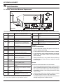
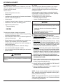
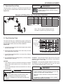
Installation Manual
Installation & Appliance Set-Up
INSTALLER: Leave this manual with party responsible for use and operation.
OWNER: Retain this manual for future reference.
NOTICE: DO NOT DISCARD THIS MANUAL
WARNING
If the information in these instructions is not followed exactly, a
fire may result causing property
damage, personal injury, or death.
MT VERNON PELLET INSERT
ADVANCED ENERGY (AE)
Model(s):
MTVERNINSAE-MBK
• Do not store or use gasoline or other flammable vapors and liquids in the vicinity of
this or any other appliance.
MTVERNINSAE-PMH
• Do not overfire - If heater or chimney connector glows, you are overfiring. Overfiring
will void your warranty.
MTVERNINSAE-CSB
• Comply with all minimum clearances to
combustibles as specified. Failure to
comply may cause house fire.
WARNING
HOT SURFACES!
Glass and other surfaces are hot
during operation AND cool down.
Tested and
Listed by
Portland
Oregon USA
O-T L
C
US
OMNI-Test Laboratories, Inc.
CAUTION
Tested and approved for wood pellets, shelled field
corn, wheat and black oil sunflower seeds. Burning of
any other type of fuel voids your warranty.
Hot glass will cause burns.
•
Do not touch glass until it is cooled
•
NEVER allow children to touch glass
•
Keep children away
•
CAREFULLY SUPERVISE children in same room as
fireplace.
•
Alert children and adults to hazards of high temperatures
•
High temperatures may ignite clothing or other
flammable materials.
•
Keep clothing, furniture, draperies and other flammable
materials away.
NOTE
CAUTION
Check building codes prior to installation.
• Installation MUST comply with local, regional, state and national codes and regulations.
• Consult local building, fire officials or authorities having jurisdiction about restrictions, installation inspection, and permits.
1
To obtain a French translation of this manual, please contact
your dealer or visit www.quadrafire.com
Pour obtenir une traduction française de ce manuel, s’il vous
plaît contacter votre revendeur ou visitez www.quadrafire.com
7036-188C
June 19, 2014
MT VERNON AE INSERT
Safety Alert Key:
•
DANGER! Indicates a hazardous situation which, if not avoided will result in death or serious injury.
•
WARNING! Indicates a hazardous situation which, if not avoided may result in death or serious injury.
•
CAUTION! Indicates a hazardous situation which, if not avoided, may result in minor or moderate injury.
•
NOTICE: Indicates practices which may cause damage to the appliance or to property.
TABLE OF CONTENTS
1 Important Safety Information ............3
4 Vent Information...............................12
A.
B.
C.
D.
E.
Appliance Certification ......................................................3
BTU & Efficiency Specifications........................................3
Glass Specifications .........................................................3
Electrical Rating................................................................3
Mobile Home Approved .................................................... 3
2 Getting Started ...................................4
A. Design, Installation & Location Considerations ..........................4
B. Thermostat Wall Control Location......................................5
C. Tools And Supplies Needed..............................................5
D. Inspect Appliance and Components .................................5
E. Install Checklist ..................................................................6
3 Dimensions and Clearances .............7
A. Appliance Dimensions ......................................................7
B. Clearances to Combustibles (UL and ULC) .......................8
C. Masonry and Zero Clearance Fireplaces ..........................9
D. Floor Protection .................................................................9
E. Minimum Opening for Masonry &
Zero Clearance Fireplaces .................................................9
F. Mantel Projections ..............................................................9
G. Removing Metal Floor of Factory-Built Firebox .................10
H. Prefabricated Metal Chimney ............................................11
I. Altering the Factory-Built Fireplace .....................................11
A. Venting Termination Minimum Requirements ...................12
B. Avoiding Smoke and Odors ...............................................13
C. Negative Pressure ............................................................14
D. Draft..... ............................................................................. 14
E. Chimney and Exhaust Connection ...................................14
F. Equivalent Feet of Pipe ....................................................15
G. Pipe Selection Chart ........................................................15
5 Venting Systems ..............................16
A. Full Reline With Outside Air - Horizontal ...........................16
B. Full Reline With Outside Air - Vertical ...............................17
6 Appliance Set-Up .............................18
A. Leveling System ...............................................................18
B. Outside Air Kit Instructions ................................................18
C. Hearth Support .................................................................19
D. Removal of Cast Sides ....................................................19
E. Surround and Trim Set - Cast ...........................................20
F. Surround & Trim Set, Basic ...............................................20
G. Optional Log Set Placement Instructions .........................21
H. Wall Control Thermostat Installation .................................21
7 Mobile Home Installation.................22
8 Accessory List .................................23
300 Watt Igniters come installed in brand new Mt. Vernon AE
units and are for pellet fuel only. The 380 Watt Igniter is required
for burning multi-grain fuels and is included in the component
pack. Multi-fuels include, corn, sunflower seeds, and wheat.
2
7036-188C
June 19, 2014
MT VERNON AE INSERT
1
Important Safety Information
A. Appliance Certification
Model
OMNI Test Laboratories, Inc.
Report No.
061-S-69-6
Type
Solid Fuel Room Heater/Pellet Type
Insert
FCC
• This appliance is approved for mobile home installations when not installed in a sleeping room and when
an outside combustion air inlet is provided.
Mt. Vernon Pellet Insert AE
Laboratory
Standard
E. Mobile Home Approved
• The structural integrity of the mobile home floor, ceiling, and walls must be maintained.
• The appliance must be properly grounded to the
frame of the mobile home and use only Listed pellet
vent Class “L” or “PL” connector pipe.
ASTM E1509-04, ULC S628-93 and
ULC/ORD-C1482-M1990 Room Heater
Pellet Fuel Burning type and (UM)
84-HUD, Mobile Home Approved.
Complies with Part 15 of FCC Rules.
Operation is subject to the following
two conditions: (1) this device may not
cause harmful interference, and (2) this
device must accept any interference
received, including interference that may
cause undesired operation.
• Outside Air Kit, part OAK-ACC must be installed in a
mobile home installation.
NOTICE: This installation must conform with local codes. In
the absence of local codes you must comply with the ASTM
E1509-04, ULC S628-93, (UM) 84-HUD and ULC/ORDC-1482-M1990.
WARNING
Fire Risk.
Hearth & Home Technologies disclaims any
responsibility for, and the warranty will be
voided by, the following actions:
B. BTU & Efficiency Specifications
EPA:
Compliant
*BTU Input:
14,620 - 52,500 / hr
Efficiency:
Up to 86.5%
Heating Capacity:
Up to 3,000 square feet depending
on climate zone
Vent Size:
3” or 4” Type “L” or “PL”
Hopper Capacity:
56 lbs +/-5 lbs
Fuels:
Pellets, Shelled Field Corn, Wheat
and Black Sunflower Seeds
Shipping Weight:
• Installation and use of any damaged appliance.
• Modification of the appliance.
• Installation other than as instructed by Hearth & Home
Technologies.
• Installation and/or use of any component part not approved by
Hearth & Home Technologies.
• Operating appliance without fully assembling all components.
• Operating appliance without legs attached (if supplied with unit).
• Do NOT Overfire - If appliance or chimney connector glows,
you are overfiring.
Any such action that may cause a fire hazard.
425 lbs
*BTU will vary, depending on the type of fuel you use in your
appliance. Consult your Quadra-Fire dealer for best results.
Improper installation, adjustment, alteration, service or
maintenance can cause injury or property damage.
For assistance or additional information, consult a qualified
installer, service agency or your dealer.
C. Glass Specifications
This stove is equipped with 5mm ceramic glass. Replace
glass only with 5mm ceramic glass. Please contact your
dealer for replacement glass.
D. Electrical Rating
115 VAC, 60 Hz, Start 5 Amps, Run 1.25 Amps
June 19, 2014
NOTE: Hearth & Home Technologies, manufacturer of
this appliance, reserves the right to alter its products, their
specifications and/or price without notice.
Quadra-Fire is a registered trademark of Hearth & Home
Technologies.
7036-188C
3
MT VERNON AE INSERT
2
Install Guide
Getting Started
A. Design, Installation & Location Considerations
1. Appliance Location
NOTICE: Check building codes prior to installation.
• Installation MUST comply with local, regional, state and
national codes and regulations.
•
Consult insurance carrier, local building inspector, fire
officials or authorities having jurisdiction over restrictions,
installation inspection and permits.
Since pellet exhaust can contain ash, soot or sparks, you
must consider the location of:
•
•
•
•
•
•
Windows
Air Intakes
Air Conditioner
Overhang, soffits, porch roofs, adjacent walls
Landscaping, vegetation
Horizontal or vertical vent termination
It is a good idea to plan your installation on paper, using exact
measurements for clearances and floor protection, before
actually beginning the installation. Location of the appliance
and chimney will affect performance.
2. Floor Support
Consideration must be given to:
Ensure that your floor will support these weights prior to
installation. Add sufficient additional support to meet this
weight requirement prior to installation. The weight of the
appliance is 425 lbs.
• Safety, convenience, traffic flow
• Placement of the chimney and chimney connector and to
minimize the use of chimney offsets.
The supporting floor under the appliance must be able to
handle the weight of the appliance, fuel load and the weight
of the chimney.
WARNING
• Place the appliance where there will be a clear passage
for a Listed chimney through the ceiling and roof (vertical)
or through exterior wall (horizontal).
Risk of Fire
Damaged parts could impair safe operation. Do
NOT install damaged, incomplete or substitute
components.
• Installing the required outside air kit will affect the location
of the vent termination.
When locating vent and venting termination, the ideal location is to vent above roof line when possible. This minimizes
the affects of wind loading.
CAUTION
If burning shelled field corn, you must use approved venting specifically designed for corn to prevent corrosion
or degradation. Follow the instructions from the venting
manufacturer.
Recommended Location:
• Above peak
Recommended Location:
• Above peak
• Inside heated space
Marginal Location:
• Below peak
Marginal Location:
• Wind loading possible
Location NOT recommended:
• Not the highest point of the roof
• Wind loading possible
Recommended:
• Insulated exterior chase
in cooler climates
Location NOT recommended:
• Too close to tree
• Below adjacent structure
• Lower roof line
• Avoid outside wall
Windward
Leeward
Recommended:
Outside Air Intake
on windward side
Multi-level Roofs
NOT recommended:
Outside Air Intake
on leeward side
Figure 4.1
4
7036-188C
June 19, 2014
MT VERNON AE INSERT
B. Thermostat Wall Control Location
D. Inspect Appliance and Components
The thermostat wall control’s location will have some affect
on the appliance’s operation.
•
Open the appliance and remove all the parts and articles
packed inside the Component Pack. Inspect all the parts
and glass for shipping damage.
•
Report to your dealer any parts damaged in shipment.
•
All labels have been removed from the glass door.
•
Plated surfaces have been wiped clean with a soft cloth,
if applicable.
•
Read all the instructions before starting the installation.
Follow these instructions carefully during the
installation to ensure maximum safety and benefit.
•
Follow pipe manufacturer instructions for installation
and air clearance requirements.
• Maximum wire length from appliance is 100 feet (30.48m)
continuous unspliced wire. Recommended 20 gauge wire,
solid copper .
• When located close to the appliance, it may require a
slightly higher temperature setting to keep the rest of the
house comfortable.
• When located in an adjacent room or on a different floor
level, you will notice higher temperatures near the appliance.
CAUTION
The wall control is an integral part of the appliance. No other
wall control or thermostat can be substituted.
C. Tools And Supplies Needed
Tools and building supplies normally required
for installation, unless installing into an existing
masonry fireplace:
Reciprocating Saw
Hammer
Tape Measure
1/4” Self-Tapping Screws
Hi-temp Caulking Material
Safety Glasses
Electric Drill & Bits (1/4”)
Channel Locks
Phillips Screwdriver
Plumb Line
Framing Material
Gloves
Framing Square
Level
May also need:
Vent Support Straps
Venting Paint
300 Watt Igniters come
installed in brand new Mt.
Vernon AE units and are
for pellet fuel only. The
380 Watt Igniter is required for burning multi-grain fuels and is included in the component pack. Multi-fuels include,
corn, sunflower seeds, and wheat.
WARNING
Risk of Fire
Damaged parts could impair safe operation.
Do NOT install damaged, incomplete or
substitute components.
WARNING
Hearth & Home Technologies disclaims any
responsibility for, and the warranty will be voided
by, the following actions:
• Installation & use of any damaged appliance.
• Modification of the appliance.
• Installation other than as instructed by Hearth & Home
Technologies.
• Installation and/or use of any component part not
approved by Hearth & Home Technologies.
• Operating appliance without fully assembling all
components.
• Operating appliance without legs attached (if supplied
with unit).
• Do NOT Overfire
Or any such action that may cause a fire hazard.
June 19, 2014
7036-188C
5
MT VERNON AE INSERT
E. Install Checklist
ATTENTION INSTALLER:
Follow this Standard Work Checklist
This standard work checklist is to be used by the installer in conjunction with, not instead of, the instructions contained in this installation manual.
Customer:
Date Installed:
Lot/Address:
Location of Fireplace:
Installer:
Dealer/ Distributor Phone #:
Serial #:
Model (circle one):
MTVERNINSAE-MBK
MTVERNINSAE-PMH
MTVERNINSAE-CSB
WARNING! Risk of Fire or Explosion! Failure to install fireplace according to these instructions can lead to a fire or explosion.
Appliance Install
YES
IF NO, WHY?
Verified clearances to combustibles. (Pg. 8)
Fireplace is leveled and liner is secured to appliance. (Pg. 18)
Hearth extension size/height decided. (Pg. 22)
Outside air kit installed. (Pg. 15)
Floor protection requirements have been met.
The masonry chimney is inspected by a professional and is clean or the
factory built metal chimney is installed according to the manufacturer’s
instructions and clearances.
Chimney Section 4 (Pg. 10)
Chimney configuration complies with diagrams.
Chimney installed, locked and secured in place with proper clearance.
Chimney meets the minimum height requirements.
Roof flashing installed and sealed.
Terminations installed and sealed.
Clearances Section 3 (Pg. 7)
Combustible materials not installed in non-combustible areas.
Verified all clearances meet installation manual requirements.
Mantels and wall projections comply with installation manual requirements.
Protective hearth strips and hearth extension installed per manual requirements.
Appliance Setup Section 5 (Pg. 15)
All packaging and protective materials removed.
Firebrick, baffle and ceramic blanket installed correctly.
All labels have been removed from the door.
All packaging materials are removed from inside/under the fireplace.
Manual bag and all of its contents are removed from inside/under the fireplace
and given to the party responsible for use and operation.
Hearth & Home Technologies recommends the following:
• Photographing the installation and copying this checklist for your file.
• That this checklist remain visible at all times on the fireplace until the installation is complete.
Comments: Further description of the issues, who is responsible (Installer/Builder/Other Trades, etc.) and corrective action needed:
Comments communicated to party responsible
by
on
(Builder/Gen. Contractor)
(Installer)
(Date)
Part # 4017-254 • Rev B • 01/29/13
6
7036-188C
June 19, 2014
MT VERNON AE INSERT
3
Dimensions and Clearances
A. Appliance Dimensions
32 in. (812mm)
23-7/8 in.
8-1/8 in.
(606mm)
(206mm)
15 in.
(382mm)
CL
2-3/8 in.
(59mm)
29-3/4 in.
(756mm)
23-7/8 in.
(605mm)
13-1/8 in.
(333mm)
26-1/4 in.
(667mm)
28-1/8 in.
(714mm)
Figure 7.1 - Top View
Figure 7.2 - Side View
36-5/8 in.
(929mm)
33 in.
838mm)
34-7/8 in.
(886mm)
46-1/8 in.
(1171mm)
50 in. (1270mm)
Figure 7.3 - Front View with Basic Surround Panel Set
June 19, 2014
Figure 7.4 - Front View with Cast Panel Set
7036-188C
7
MT VERNON AE INSERT
B. Clearances to Combustibles (UL and ULC)
Built-in Unit - Rear Vent
A
D
C
B
B
C
E
0 inch Clearance To Exposed Section And Face Trim
Figure 8.1
Location
A
Top of Hopper
Configuration
Inches
Millimeters
3
76
Top or Rent Vent
B
Side of Outside Skin
Top or Rear Vent
2
51
C
Back of Hopper
Top Vent
7-1/2
191
Rear Vent
2-3/4
70
D
Vent Pipe to Combustible
Top or Rear Vent
3
76
E
Cast Side to Side Wall
Top or Rear Vent
6
152
Built-in Unit - Rear Vent with Outside Air
WARNING
Fire Risk.
Comply with all minimum
clearances to combustibles as
specified.
Failure to comply may cause house fire.
NOTE:
•
•
•
Illustrations reflect typical installations
and are FOR DESIGN PURPOSES
ONLY.
Illustrations/diagrams are not drawn to
scale.
Actual installation may vary due to
individual design preference.
Figure 8.2
8
7036-188C
June 19, 2014
MT VERNON AE INSERT
Built-In Vertical
E. Minimum Opening for Masonry & Zero
Clearance Fireplaces
A
C
B
Figure 9.3
Location
Figure 9.1
C. Masonry and Zero Clearance Fireplaces
Inches
Millimeters
F
Rear Width
24
610
G
Depth
15
381
H
Height
23-7/8
606
I
Front Width
34
864
Face
Trim
Mantel
Side Wall
F. Mantel Projections
B
A
J
C
K
D
E
Figure 9.2
Location
A
Insert side to combustible side wall
Inches
6
Millimeters
152
B
Insert top to max. 2-1/4 inch face trim
0
0
C
Insert side to max. 2-1/4 inch face trim
0
0
D. Floor Protection
Location
Inches
Millimeters
D
Floor protection hearth extension from
door opening
6
152
E
Floor protection to the side of door
opening
6
152
•
•
Figure 9.4
Use a non-combustible floor protector, extending beneath
appliance and to the front, and sides as indicated.
If employing a hearth extension, any parts or materials used
in construction must be non-combustible.
June 19, 2014
The maximum mantel depth (J) is 12 inches (305mm)
with a minimum vertical height (K) of 12 inches (305mm).
However if your mantel has a depth of 10 inches (254mm)
then the vertical minimum height is 10 inches (254mm).
7036-188C
9
MT VERNON AE INSERT
G. Removing Metal Floor of Factory-Built
Firebox
•
•
•
The firebrick (refractory), glass doors, screen rails,
screen mesh and log grates can be removed from a factory-built firebox in order to gain minimum insert opening requirements.
Any smoke shelves, shields and baffles may be removed
from a factory-built firebox if attached with mechanical
fasteners.
Use 2 x 4 from insert
packaging to support insert
The metal floor of the factory-built firebox may be
removed to facilitate the installation of the insert only
when a 1/4 inch (6mm) airspace is provided between
the insert and the floor of outer wrap.
The following is only one example as there are many different models of factory-built fireplaces.
Figure 10.3. If the floor is made of thin metal,
we recommend using the 2 x 4 from the insert
packaging to support the insert. The 2 x 4
may need to be cut to the appropriate size.
Starter hole
Keep sharp edge of
metal floor away from
power cord
Mark area of
floor to cut
Figure 10.1. Measure and mark the metal
floor for cutting. With a drill, make a starter
hole in each corner.
Figure 10.4. Place the insert into the factory-built firebox. Ensure that the power cord
can not be damaged by the sharp metal
edge. You may need to cut out a notch to
accommodate the cord.
Leveling Leg
Figure 10.2. Using a saws-all, cut out the
floor.
Figure 10.5. Ensure that the leveling leg is
positioned over the 2 x 4 before leveling the
insert.
10
7036-188C
June 19, 2014
MT VERNON AE INSERT
H. Prefabricated Metal Chimney
I. Altering the Factory-Built Fireplace
The chimney can be new or existing, masonry or prefabricated
and must meet the following minimum requirements:
•
• Must be minimum 6 inch (152mm) inside diameter of
high temperature chimney listed to UL 103 HT (2100oF)
or ULC-S628.
The following modifications are permissible:
•
•
•
•
•
•
• Must use components required by the manufacturer for
installation.
• Must maintain clearances required by the manufacturer
for installation.
• Refer to manufacturers instructions for installation
•This insert is listed to ASTM E 1509 Standard and is
approved for installation into listed factory-built zero
clearance fireplaces listed to UL 127 conforming to the
following specifications and instructions:
•The liner must be securely attached to the insert flue collar
and the chimney top.
•The air flow of the factory-built zero-clearance fireplace
system must not be altered. The flue liner top support
attachment must not reduce the air flow for the existing
air-cooled chimney system.
•No dilution air is allowed to enter the chimney.
Removal of damper or locked in open position
Removal of smoke shelf or baffle
Removal of ember catches
Removal of fire grate
Removal of view screen/curtain
Removal of doors
•
External trim pieces which do not affect the operation of
the fireplace may be removed providing they can be stored
on or within the fireplace for reassembly if the insert is
removed.
•
The permanent metal warning label provided must be
attached to the back of the fireplace, with screws or
nails, stating that the fireplace may have been altered to
accommodate the insert, and must be returned to original
condition for use as a conventional fireplace. Figure 11.1
•
If the hearth extension is lower than the fireplace opening,
the portion of the insert extending onto the hearth must be
supported.
•
Manufacturer designed adjustable support kit can be
ordered from your dealer.
•
Final approval of this installation type is contingent upon
the authority having jurisdiction.
•The original factory-built clearance fireplace chimney
cap must be re-installed after installing the approved
chimney liner meeting type UL 103 HT requirements
(2100°F) per UL 1777.
•If the chimney is not listed as meeting HT requirements,
or if the factory built fireplace was tested prior to 1998, a
full height listed chimney liner must be installed from the
appliance flue collar to the chimney top.
The fireplace must not be altered, except for the exceptions
listed below. Do not remove the bricks and mortar from
the existing fireplace.
NOTE: Refer to chimney liner manufacturer for recommendations on supporting the liner. Installation into
fireplaces without a permit will void the listing
1. Secure the fireplace damper in the open position. If
this cannot be accomplished, it will be necessary to
remove the damper
WARNING
2. Seal damper area of chimney around chimney
connector with a high temperature sealant or seal
insert against the face of the fireplace.
Fire Risk.
Follow venting manufacturer’s clearances and
instructions when installing venting system.
3. Both methods must be removable and replaceable
for cleaning and re-installation.
NOTICE: In Canada when using a factory-built chimney it
must be safety listed, Type UL103 HT (2100oF) [1149oC]
CLASS “A” or conforming to CAN/ULC-S629M, STANDARD FOR 650oC FACTORY-BUILT CHIMNEYS.
WARNING
THIS FIREPLACE MAY HAVE BEEN ALTERED
TO ACCOMMODATE AN INSERT. IT MUST BE
RETURNED TO ITS ORIGINAL CONDITION
BEFORE USE AS A SOLID FUEL BURNING
FIREPLACE.
250-2061
250-2061
Figure 11.1
June 19, 2014
7036-188C
11
MT VERNON AE INSERT
4
Vent Information
A. Venting Termination Minimum Requirements
V
N
V
N
Inside Corner
Electrical
Service
N
V
N
V
G
V
A
D
O
V
P
E
L
C
V B
FIXED
CLOSED
V
F
FIXED
CLOSED
OPEN
V
B
OPEN
G
M
V
V
V Termination Cap
I
A
B
B
Figure 12.1
H
X Air Supply Inlet
V
X
J or K
G Gas Meter
Restricted Area
All minimum clearances are listed with an Outside Air Kit (OAK) installed, unless otherwise noted in table below.
A
12 in.
Above Finish Grade (the grade surface
must be a non-combustible material
24 in.
Above grass, top of plants, wood or any other combustible
B
12 in.
48 in. no OAK
Open door or window: below or to the side
12 in.
36 in. no OAK
Clearance from any forced air intake of other appliance
B
12 in.
Open door or window: above
12 in.
Clearance horizontally from combustible wall
C
6 in.
Permanently closed window: above, below
or to the side
15 in.
Vented directly through a wall, minimum length of
horizontal pipe
D
18 in.
36 in. no OAK
Vertical clearance to a ventilated soffit
located above the terminal within a horizontal distance of 2 ft from the center-line
of the terminal
6 in. horizontal
12 in. vertical
Minimum horizontal or vertical terminations must
protrude from wall
NOTICE:
E
12 in.
Clearance to unventilated soffit
Do NOT Terminate Vent:
F
12 in.
Clearance to outside corner
•
G
12 in.
Clearance to inside corner
In any location that will allow flue gases or soot from entering or staining the building
H
36 in.
Above gas meter/regulator measured from
horizontal center-line of regulator
•
In any location which could create a nuisance or hazard
I
36 in. USA
72 in. Canada
Clearance to service regulator vent outlet
•
J
12 in.
48 in. no OAK
Clearance to non-mechanical air supply
inlet to the building or the combustions air
inlet to any other appliance
In any enclosed or semi-enclosed area such as a carport,
garage, attic, crawl space, under a sun deck or porch,
narrow walkway
•
K
10 ft horizontal
3 ft vertical
Clearance to mechanical air supply
Closely fenced area, or any location that can build up
a concentration of fumes such as a stairwell, covered
breezeway, etc.
L
7 ft.
Above paved sidewalk, paved driveway
located on public property
M
12 in.
Under an open veranda, porch, deck or
balcony
N
See Note
below*
Electric service: above, below or to the
side (location must not obstruct or interfere
with access)
O
24 in.
Adjacent building, fences and protruding
parts of the structure
P
12 in.
Clearance above roof line for vertical
terminations
NOTICE:
Termination must exhaust above air inlet elevation.
*NOTE: Consult local building, fire officials or authorities having jurisdiction. Local codes or regulations may require different clearances.
12
•
It is recommended that at least 60 inches (1.52m) of vertical
pipe be installed when appliance is vented directly through a
wall. This will create a natural draft, which will help prevent
the possibility of smoke or odor venting into the home during
a power outage.
•
It will also keep exhaust from causing a nuisance or hazard
by exposing people or shrubs to high temperatures.
•
The safest and preferred venting method is to extend the vent
vertically through the roof or above the roof.
7036-188C
June 19, 2014
MT VERNON AE INSERT
B. Avoiding Smoke and Odors
Vent Configurations
Negative Pressure, Shut-Down and Electrical Power
Failure
To reduce probability of reverse drafting during shut-down
conditions Hearth & Home Technologies strongly recommends:
To reduce the probability of back-drafting or burn-back in
the pellet appliance during power failure or shut down conditions, it must be able to draft naturally without exhaust
blower operation.
•
Installing the pellet vent with a minimum vertical run of
5 feet (1.52m). Preferably terminating above the roof
line.
•
Installing the outside air kit at least 4 feet (1.22m) below
the vent termination.
Negative pressure in the house will resist this natural draft if
not accounted for in the pellet appliance installation.
Heat rises in the house and leaks out at upper levels. This
air must be replaced with cold air from outdoors which flows
into lower levels of the house.
Vents and chimneys into basements and lower levels of the
house can become the conduit for air supply and reverse
under these conditions.
Outside Air
An outside air kit is recommended in all installations. The
Outside Air Kit must be ordered separately.
Per national building codes, consideration must be given to
combustion air supply to all combustion appliances. Failure
to supply adequate combustion air for all appliance demands
may lead to back-drafting of those and other appliances.
To prevent soot damage to exterior walls of the house and to
prevent re-entry of soot or ash into the house:
•
Maintain specified clearances to windows, doors and
air inlets, including air conditioners.
•
Vents should not be placed below ventilated soffits.
Run the vent above the roof.
•
Avoid venting into alcove locations.
•
Vents should not terminate under overhangs, decks or
onto covered porches.
•
Maintain minimum clearance of 12 inches (305mm)
from the vent termination to the exterior wall. If you
see deposits developing on the wall, you may need to
extend this distance to accommodate your installation
conditions.
When the appliance is roof vented (strongly recommended):
The air intake is best located on the exterior wall oriented
towards the prevailing wind direction during the heating
season.
When the appliance is side-wall vented:
The air intake is best located on the same exterior wall as
the exhaust vent outlet and located lower on the wall than
the exhaust vent outlet.
The outside air supply kit can supply most of the demands of
the pellet appliance, but consideration must be given to the
total house demand.
House demand may consume the air needed for the appliance. It may be necessary to add additional ventilation to
the space in which the pellet appliance is located.
Consult with your local HVAC professional to determine the
ventilation demands for your house.
June 19, 2014
CAUTION
• DO NOT CONNECT THIS UNIT TO A CHIMNEY FLUE
SERVICING ANOTHER APPLIANCE.
• DO NOT CONNECT TO ANY AIR DISTRIBUTION DUCT
OR SYSTEM.
Optional Battery Back-Up
Hearth & Home Technologies supplies an optional battery
back-up system that operates the appliance during power
failure conditions to prevent smoking. In shutdown mode,
the battery back-up will not prevent smoking.
Hearth & Home Technologies assumes no responsibility for,
nor does the warranty extend to, smoke damage caused
by reverse drafting of pellet appliances under shut down or
power failure conditions.
7036-188C
13
MT VERNON AE INSERT
C. Negative Pressure
D. Draft
Negative pressure results from the imbalance of air available for the appliance to operate properly. It can be strongest
in lower levels of the house.
Draft is the pressure difference needed to vent an appliance successfully. When an appliance is drafting successfully, all combustion byproducts are exiting the home
through the chimney.
Causes include:
Install through the warm airspace enclosed by the building envelope. This helps to produce more draft, especially
during lighting and die-down of the fire.
•
Exhaust fans (kitchen, bath, etc.)
•
Range hoods
•
Combustion air requirements for furnaces, water heaters
and other combustion appliances
•
Clothes dryers
•
Location of return-air vents to furnace or air conditioning
•
Imbalances of the HVAC air handling system
•
Upper level air leaks such as:
•
•
Preventing negative pressure
Location of appliance and chimney
NOTICE
HEARTH & Home Technologies assumes no responsibility
for the improper performance of the chimney system caused
by:
• Inadequate draft due to environmental conditions
• Downdrafts
• Tight sealing construction of the structure
• Mechanical exhausting devices
- Recessed lighting
- Attic hatch
- Duct leaks
To minimize the effects of negative air pressure:
•
Considerations for successful draft include:
Install the outside air kit with the intake facing prevailing
winds during the heating season
•
Ensure adequate outdoor air for all combustion appliances
and exhaust equipment
•
Ensure furnace and air conditioning return vents are not
located in the immediate vicinity of the appliance
•
Avoid installing the appliance near doors, walkways or
small isolated spaces
•
Recessed lighting should be a “sealed can” design
•
Attic hatches weather stripped or sealed
•
Attic mounted duct work and air handler joints and seams
taped or sealed
WARNING
Risk of Asphyxiation!
Negative pressure can cause spillage of combustion fumes
and soot.
E. Chimney and Exhaust Connection
1. Chimney & Connector: Use 3 or 4 inch (76-102mm)
diameter type “L” or “PL” venting system. It can be vented
vertically or horizontally.
2. Mobile Home: Approved for all Listed pellet vent. If using
the 3 inch (76mm) vertical Top Vent Adapter Kit or the 3
to 6 inch (76-152mm) Top Vent Offset Adapter, use Listed
double wall flue connector. A Quadra-Fire Outside Air Kit
must be used with manufactured home installations.
3. Residential: The 3 inch (76mm) vertical Top Vent Adapter
Kit and the 3 to 6 inch (76-152mm) Top Vent Offset Adapter
are tested to use 24 gauge single wall flue connector or
Listed double wall flue connector to Class A Listed metal
chimneys, or masonry chimneys meeting International
Residential Code standards for solid fuel appliances.
4. INSTALL VENT AT CLEARANCES SPECIFIED BY THE
VENT MANUFACTURER.
5. Secure exhaust venting system to the appliance with at
least 3 screws. Also secure all connector pipe joints with
at least 3 screws through each joint.
6. DO NOT INSTALL A FLUE DAMPER IN THE EXHAUST
VENTING SYSTEM OF THIS UNIT.
7. DO NOT CONNECT THIS UNIT TO A CHIMNEY FLUE
SERVING ANOTHER APPLIANCE.
NOTE: All pipe must be welded seam pipe whenever possible. Seal pipe joints with high temperature silicone (500°F
[260°C] minimum rated only).
NOTE: If burning shelled field corn, you must use approved
venting specifically designed for corn. Follow the instructions
from the venting manufacturer.
14
7036-188C
June 19, 2014
MT VERNON AE INSERT
F. Equivalent Feet of Pipe
WARNING
The table below can help you calculate the equivalent feet
of pipe which is a method used to determine pellet vent size.
Figure 15.1.
Vent surfaces get HOT, can cause burns if
touched. Non-combustible shielding or guards
may be required.
Example of 3 Elbow-Rear Vent Termination Calculation
Pellet Venting
Component
# of
Elbows
90o Elbow or Tee
3
2 ft.
Feet of Multiplied
Pipe
By
45o Elbow
3 ft.
Equivalent
Feet
Equivalent Feet
X
5
15
X
3
Horizontal Pipe
7
X
1
Vertical Pipe
2
X
0.5
Components
7
1
Total Equivalent Feet
23
2 ft.
Note: This is a generic example and is not
intended to represent any specific fuel type.
2 ft.
Figure 15.1
G. Pipe Selection Chart
30
The chart will help you in determining proper venting size
according to the equivalent feet of pipe calculated previously
and the altitude above sea level of this installation.
Figure 15.2
4 in. (102mm) Diameter Pipe Only
Example 1
20
Equivalent Pipe
Length In Feet
Example 2
a. Locate the calculated equivalent feet of pipe on the vertical
left side of the chart.
10
3 in. or 4 in. (76mm or 102mm) Diameter Pipe
b. Move to the right horizontally on the chart until you reach
your altitude above sea level.
0
1
2
3
4
5
6
7
8
9
10
ALTITUDE IN THOUSANDS OF FEET
c. If you fall below the diagonal line, 3 or 4 inch (76 to 102mm)
pipe may be used.
Figure 15.2
d. If it is anywhere above the diagonal line, a 4 inch (102mm)
diameter pipe is required.
Example 1: If the equivalent length of pipe is 23 feet (7m) with
altitude of 8,000 feet (2438m) you must use 4 inch (102mm)
diameter type “L” or “PL” vent.
NOTICE:
•
A 90° elbow is 5 times as restrictive to the flow of exhaust
gases under positive pressure as 1 foot (305mm) of horizontal pipe.
•
A foot of horizontal pipe is twice as restrictive as a foot of
vertical pipe.
Example 2: If the equivalent length of pipe is 12 feet (3.7m)
with altitude of 6,000 feet (1829m) you may use 3 or 4 inch
(76 to 102mm) diameter type “L” or “PL” vent.
WARNING
RISK OF INJURY OR PROPERTY DAMAGE!
WARNING
•
Fire Risk.
• Only LISTED venting components may be used.
Improper installation, adjustment, alteration, service or maintenance can cause injury or property damage.
•
Refer to the owner’s information manual provided with this
appliance.
•
For assistance or additional information consult a qualified
installer, service agency or your dealer.
• NO OTHER vent components may be used.
• Substitute or damaged vent components may impair safe
operation.
June 19, 2014
7036-188C
15
MT VERNON AE INSERT
5
Venting Systems
A. Full Reline With Outside Air - Horizontal
WARNING
Fire Risk.
Inspection of Chimney:
• Masonry chimney must be in good condition.
• Meets minimum standard of NFPA 211
• Factory-built chimney must be a minimum 6 inch
(152mm) UL103 HT.
CAUTION
Never draw outside combustion air from:
• Wall, floor or ceiling cavity
• Enclosed space such as an attic or garage
NOTE; Use metal plate around
exhaust vent pipe and seal all
edges with non-flammable insulation such as fiberglass, mineral
wool or ceramic.
Do not use high temperature
caulking materials to seal any
edge to prevent furture serviceability.
Outside Air through Rear
Wall (Horizontal)
Figure 16.1
NOTE:
In Canada, where passage through a wall or partition of combustible construction is desired, the installation shall conform
to CAN/CSA-B365.
16
NOTE:
• Illustrations reflect typical installations and are FOR
DESIGN PURPOSES ONLY.
• Illustrations/diagrams are not drawn to scale.
• Actual installation may vary due to individual design
preference.
7036-188C
June 19, 2014
MT VERNON AE INSERT
B. Full Reline With Outside Air - Vertical
NOTE: Check clearances carefully for this type of installation to ensure adequate room for outside air venting.
NOTE: In Canada only a full reline is allowed per ULC
S628, ORD ULC C1482-M1990.
305mm min.
above
305mm min.
below
NOTE; Use metal plate around
exhaust vent pipe and seal all
edges with non-flammable insulation such as fiberglass, mineral
wool or ceramic.
Outside Air
Termination
at
Chimney Top
(Vertical)
Do not use high temperature caulking materials to seal any edge to
prevent furture serviceability.
Figure 17.1
NOTE: In Canada this fireplace insert must be installed
with a continuous chimney liner of 6 inch (152mm) diameter extending from the fireplace insert to the top of the
chimney. The chimney liner must conform to the Class
3 requirements of CAN/ULC-S635, Standard for Lining
Systems for Existing Masonry or Factory-Built Chimneys
and Vents, or CAN/ULC-S640, Standard for Lining Systems for New Masonry Chimneys.
June 19, 2014
CAUTION
Check building codes prior to installation.
• Installation MUST comply with local, regional, state and
national codes and regulations.
• Consult local building, fire officials or authorities having jurisdiction about restrictions, installation inspection, and permits.
7036-188C
17
MT VERNON AE INSERT
6
Appliance Set-Up
A. Leveling System
B. Outside Air Kit Instructions
The leveling bolts are located on the sides of the appliance,
front and rear. To access the bolts, remove the front access
panels. Reach in and turn the bolt to the desired height to
level the appliance.
Included in Kit: 2 wire ties, 1 collar assembly,
1 termination cap assembly, 1 trim ring, fasteners.
NOTE: 3 INCH (76mm) ALUMINUM FLEX PIPE NOT
INCLUDED.
Tools Needed: Phillips head screw driver; wire cutters;
hole saw or jig saw.
1. Measure distance from floor to air vent opening in appliance and mark location on wall.
2. Use saw to cut opening in wall. Cut a 3-1/2 to 4 inch
(89-102mm) opening on inside wall and a 4 to 4-1/2 inch
(102-114mm) opening on outside of house.
3. Use wire ties to secure flex pipe to collar assembly.
4. Slide trim ring over flex pipe and run pipe through wall.
5. Attach flex pipe (not included) to outside termination cap
with second wire tie.
6. Secure termination cap to outside surface.
7. Secure trim ring to interior wall.
Leveling Bolts - 2 on each side
CAUTION
Never draw outside combustion air from:
• Wall, floor or ceiling cavity
• Enclosed space such as an attic or garage
Figure 18.1
Collar
Wire Ties
3 inch Aluminum Flex
Pipe (not included)
Trim Ring
Termination Cap
Figure 18.2
18
7036-188C
June 19, 2014
MT VERNON AE INSERT
C. Hearth Support
Included in Kit: (1) bottom, (1) trim front, (2) trim sides, (2)
trim extensions
Tools Needed: Phillips head screw driver, measuring tape,
gloves
7. Place the assembled hearth support under the insert.
Lower the leveling bolts if necessary to keep the insert
level.
8. Open the door and attach the hearth support to the insert.
There are 9 attachment holes. Figure 19.3.
1. Remove contents from box and lay on protective surface
to avoid scratching the paint.
2. Lay front and sides face down. Bend the tabs down toward
the inside. Figure 19.1.
9 attachment holes - 3 on
each side and 3 in the front
3. The side pieces are shipped flat. It is must easier to flex the
sides into a bowed position before installing.
4. Lay the cast bottom face up. Attach the 2 sides FIRST and
then the front piece. Figure 19.2.
5. Turn the cast bottom right side up and attach the panel
extensions. Note the alignment hole.
6. Attach the appropriate footers depending on the panels &
trim set you are installing. The footers come in 2 sizes, 3
and 5 inches. Discard the footers not used.
Figure 19.3
D. Removal of Cast Sides
You will need to remove the cast sides in order to install
the panel and trim set.
1. There is a latch on the back side of the cast side in the
middle of the top opening of the cast side as indicated
in Figure 19.4.
Bend tabs down. Shipped
flat from the factory.
2. Place your fingers inside the opening and squeeze
the latch. The side can now be pulled toward you and
removed. Place on a protective surface so as not to
damage the finish.
3. To replace the side, set the bottom in first. Squeeze
the latch in an open position. Place the cast side into
position and then release the latch. The latch hooks
onto a bracket to hold the side in place.
Figure 19.1
3 inch
high Set
Location of Latch
for Removing
Cast Sides
Attach Trim to Insert from
inside Insert.
5 inch
high Set
Lower the leveling
bolts if necessary to
keep the insert level
when installing the
Hearth Support.
3 in
Basic
Cast
5 in
Install Front Trim Last,
Corner Overlap Side
Trim Pieces
Figure 19.2
June 19, 2014
Attach Trim to Base
from underneath
Figure 19.4 - Shown with Cast Panel Set
7036-188C
19
MT VERNON AE INSERT
E. Surround and Trim Set - Cast
F. Surround & Trim Set, Basic
Included in Surround Kit: (2) side panels, left and right;
(1) panel top; (1) fastener package.
Included in Surround & Trim Kit: (2) corner brackets and set
screws; (1) trim set, 3 piece; (2) side panels; (1) top panel;
(4) screws.
Included in Cast Trim Kit: (2) cast trim legs, left and right;
(1) cast trim header; (2) cast trim footers, left and right; (1)
fastener package.
Tools Needed: Powered Phillips head screw driver
Tools Needed: Powered Phillips head screw driver
1. Secure the top panel to the surround sides with the
screws provided. Figure 20.3
1. Remove contents from box being careful not to scratch or
damage the cast trim pieces.
2. Assemble the trim with the (2) corner brackets provided.
Figure 20.4
2. Lay the surround set face down on protective covering to
prevent scratching the painted surface.
3. Remove the 2 cast sides and slide the assembled trim
over the assembled surround set. Figure 20.5
3. Secure the surround legs to top panel with the screws
provided.
4.
4. Now bend the tabs down toward the backside of the panel
set, 5 on top and 2 on each leg. Leave the panel set face
down. Figure 20.1
Carefully slide surround and trim over the top of the insert
into place matching the mounting holes on the panel with
the mounting holes on the insert. Secure with screws
provided. Figure 20.5
5. Place the corresponding cast trim pieces ( 2 cast trim legs
and 1 cast trim header) underneath the panel set, also face
down.
Back of Top Surround
6. Place washer provided over tab and secure the trim and
panel together with screw. Continue for all tabs.
Screws
7. Secure cast footers with screws.
8. Remove both left and right cast sides from insert. Figure
20.5
Back of Side Surround
Figure 20.3
9. Carefully slide surround and trim over the top of the
insert into place matching the mounting holes on the
panel with the mounting holes on the insert. Secure with
screws provided. Figure 20.5.
2. Bend tabs down
1. Screw panels
together
1. Screw panels
together
2. Bend tabs
down
Figure 20.4
3. Install Cast Trim Header
Figure 20.1
Shown with Trim Installed on Surround Set
Figure 20.2- Completed View
20
Figure 20.5
7036-188C
June 19, 2014
MT VERNON AE INSERT
G. Optional Log Set Placement Instructions
2 PIECE LOG SET INSTALLATION
1. Place the left log as shown. There are 2 indentations in
the bottom of the log to fit over the screw heads in the
firebox. Figures 21.1 and 21.2.
2. Place the right log in front of the 2 screw heads in the
firebox. Figures 21.3 & 21.4.
CAUTION
The center 3 screws are for the wall control thermostat
wires and the 2 outer screws are mounting screw and
should not have wires attached to them.
The thermostat wires are color coded. The green wire
is on the top, the white in the middle and the red on the
bottom. Figure 21.5
There are colored dots corresponding with the same
colored wire on the right side which are easily seen by
the installer. If by chance it is put in upside down the
dots will be on the left side and will not be visible.
Logs are FRAGILE. Use extreme care when handling or
cleaning logs.
Log has indentations on the
bottom to fit over the screw
heads.
CAUTION
Shock hazard.
• Do NOT remove grounding prong from plug.
• Plug directly into properly grounded 3 prong
receptacle.
• Route cord away from appliance.
• Do NOT route cord under or in front of appliance.
Left Log
Figure 21.2
Log fits over screws
Figure 21.1
12 volt power inlet (for
optional battery back-up)
Right Log
Household power inlet
Log rests in front of screws
Green wire
White wire
Red wire
Figure 21.4
Figure 21.3
NOTICE:
Due to the abrasive nature of a pellet appliance fire, the logs
are not covered under warranty. Any placement variation
other than shown here can cause excessive heat and shall
void the appliance warranty.
Thermostat wires in center 3 screws
H. Wall Control Thermostat Installation
1.
When mounting the wall control thermostat on the wall,
be sure to follow your wall control’s installation instructions carefully.
NOTE: The wall control thermostat should be mounted on an inside wall and not in direct line with the
appliance convection air.
NOTE: If the wall control thermostat is located too
close to the appliance, you may need to set the
temperature setting slightly higher to maintain the
desired temperature in your home.
2.
There is a 5 screw terminal block located at the lower
left of the appliance, behind the cast side.
June 19, 2014
Figure 21.5
7036-188C
21
MT VERNON AE INSERT
7
Mobile Home Installation
CAUTION
You must use a Quadra-Fire Outside Air Kit
for installation in a mobile home.
1.
An outside air inlet must be provided for the combustion
air and must remain clear of leaves, debris, ice and/or
snow. It must be unrestricted while the appliance is in
use to prevent room air starvation which causes smoke
spillage. Smoke spillage can also set off smoke alarms.
2.
The combustion air duct system must be made of metal.
It must permit zero clearance to combustible construction and prevent material from dropping into the inlet or
into the area beneath the dwelling and contain a rodent
screen.
3.
The appliance must be secured to the mobile home
structure by bolting it to the floor (using lag bolts). Use
the same holes that secured the appliance to the shipping
pallet.
4.
The appliance must be grounded with #8 solid copper
grounding wire or equivalent, terminated at each end
with an NEC approved grounding device.
5.
Refer to Clearances to Combustibles and floor protection
requirements on page 8 for listings to combustibles and
appropriate chimney systems.
6.
THE STRUCTURAL INTEGRITY OF THE MOBILE
HOME FLOOR, WALL AND CEILING/ROOF MUST BE
MAINTAINED
Do NOT cut through:
• Floor joist, wall, studs or ceiling trusses.
• Any supporting material that would affect the structural
integrity.
This unit is to be connected to a factory-built chimney
conforming to CAN/ULC-S629, Standard for 650°C Factory-Built Chimneys.
For removal of the chimney for mobile home
transportation, contact the proper transportation officials.
Spark Arrestor Cap
Storm Collar
Roof Flashing
Use silicone to create an effective vapor barrier at the
location where the chimney or other component penetrates to the exterior of the structure.
7.
Follow the chimney manufacturer’s instructions when
installing the vent system for use in a mobile home.
8.
Installation shall be in accordance with the Manufacturers
Home & Safety Standard (HUD) CFR 3280, Part 24.
Joist Shield/Firestop
Approved Class L
or PL Pellet Vent
Figure 22.1
CAUTION
Never draw outside combustion air from:
• Wall, floor or ceiling cavity
• Enclosed space such as an attic or garage
WARNING
Products of combustion generate carbon monoxide and
different fuels generate different levels. Carbon monoxide
• Only use approved fuels in this appliance.
• Always keep door shut during operation. Operating
this unit with doors open can allow CO to leak into the
home.
WARNING
It is critical to have a working smoke detector
installed in the home of unit operation.
•
Smoke alarms that are properly installed and
maintained play a vital role in reducing fire deaths and
injuries. Having a working smoke alarm reduces the
chance of fire related injuries.
WARNING
CO can kill you before you are aware it is in your home.
At lower levels of exposure, CO causes mild effects that
are often mistaken for the flu. These symptoms include
headaches, dizziness, disorientation, nausea and fatigue.
The effects of CO exposure can vary greatly from person
to person depending on age, overall health and the
concentration and length of exposure.
NEVER INSTALL IN A SLEEPING ROOM.
22
7036-188C
June 19, 2014
MT VERNON AE INSERT
8
Accessory List
R
MT VERNON INSERT-AE
Service Parts
Beginning Manufacturing Date: Sept. 2006
Ending Manufacturing Date: Active
IMPORTANT: THIS IS DATED INFORMATION. Parts must be ordered from a dealer or distributor. Hearth and
Home Technologies does not sell directly to consumers. Provide model number and serial number when
requesting service parts from your dealer or distributor.
ITEM
DESCRIPTION
COMMENTS
Stocked
at Depot
PART NUMBER
Accessories
12 Volt Power Cord
12VCORD-AE
Y
Damper, 3 Inch - Tall Vertical Installs Only
PEL-DAMP3
Y
Damper, 4 Inch - Tall Vertical Installs Only
PEL-DAMP4
Firescreen
SCR-7005
Hearth Support
Log Set (2 Pc)
ZCSPT-MVI
Sold as set only
LOGS-60-AE-B
Outside Air Kit
OAK-3
Surround, Std, Panel, For Cast Trim
SP-MTVS-CST
Component Pack
7036-041
Surround, Std, Panel, w/Gold Trim
SP-MTVS-GD
Component Pack
7036-042
Trim, Panel Set, Gold
250-4660
Surround, Std, Panel w/Nickel Black Trim
SP-MTVS-NB
Component Pack
7036-042
Trim Set, Black Nickel
Trim Cast
Footer, Left
Footer, Right
Header
Trim Leg, Left
Trim Leg, Right
June 19, 2014
Y
7019-027
Matte Black
811-0930
Sienna Bronze
TR-CAST-CSB
Willow
TR-CAST-CWL
Mahogany
811-0960
Matte Black
414-7090MBK
Sienna Bronze
414-7090CSB
Willow
414-7090CWL
Mahogany
414-7090PMH
Matte Black
414-7100MBK
Sienna Bronze
414-7100CSB
Willow
414-7100CWL
Mahogany
414-7100PMH
Matte Black
414-7110MBK
Sienna Bronze
414-7110CSB
Willow
414-7110CWL
Mahogany
414-7110PMH
Matte Black
414-7120MBK
Sienna Bronze
414-7120CSB
Willow
414-7120CWL
Mahogany
414-7120PMH
Matte Black
414-7130MBK
Sienna Bronze
414-7130CSB
Willow
414-7130CWL
Mahogany
414-7130PMH
7036-188C
23
CONTACT INFORMATION
Hearth & Home Technologies
1445 North Highway
Colville, WA 99114
Division of HNI INDUSTRIES
Please contact your Quadra-Fire dealer with any questions or concerns.
For the number of your nearest Quadra-Fire dealer
log onto www.quadrafire.com
CAUTION
DO NOT DISCARD THIS MANUAL
• Important operating and • Read, understand and
follow these instrucmaintenance instructions for safe installations included.
tion and operation.
• Leave this manual with
party responsible for use
and operation.
D
DI O N
SC O
AR T
D
We recommend that you record the following pertinent
information for your heating appliance.
Date purchased/installed:
Serial Number:
Location on appliance:
Dealership purchased from:
Dealer phone:
Notes:
This product may be covered by one or more of the following patents: (United States) 5341794, 5263471, 6688302, 7216645, 7047962
or other U.S. and foreign patents pending.
24
7036-188C
June 19, 2014