1
Administrators Guide
Wyse Winterm™ 3 series,
Based on Microsoft Windows CE
®
®
Issue: 060606
PN: 883751-09 Rev. A
®
Copyright Notices
© 2006, Wyse Technology Inc. All rights reserved.
This manual and the software and firmware described in it are copyrighted. You may not reproduce, transmit,
transcribe, store in a retrieval system, or translate into any language or computer language, in any form or by any
means, electronic, mechanical, magnetic, optical, chemical, manual or otherwise, any part of this publication
without express written permission.
End User License Agreement (“License”)
A copy of the Wyse Technology End User License Agreement is included in the software and provided for your
reference only. The License at http://www.wyse.com/license as of the purchase date is the controlling licensing
agreement. By copying, using, or installing the software or the product, you agree to be bound by those terms.
Notice Regarding the MPEG-4 Visual Standard
The software installed on this device may include MPEG-4 visual decoding technology. MPEG LA, L.L.C. requires
the following notice:
USE OF THIS PRODUCT IN ANY MANNER THAT COMPLIES WITH THE MPEG-4 VISUAL STANDARD IS
PROHIBITED, EXCEPT FOR USE DIRECTLY RELATED TO (A) DATA OR INFORMATION (i) GENERATED BY
AND OBTAINED WITHOUT CHARGE FROM A CONSUMER NOT THEREBY ENGAGED IN A BUSINESS
ENTERPRISE, AND (ii) FOR PERSONAL USE ONLY; AND (B) OTHER USES SPECIFICALLY AND
SEPARATELY LICENSED BY MPEG LA, L.L.C.
If you have questions regarding this Notice, please contact MPEG LA, L.L.C., 250 Steele Street, Suite 300,
Denver, Colorado 80206; Telephone 303 331.1880; FAX 303 331.1879.
Trademarks
Wyse, WY, and WyseWorks are registered trademarks, and the Wyse logo, Winterm logo, Wyse, Winterm, Wyse
Expedian, and Alcatraz are trademarks of Wyse Technology Inc. Rapport is a registered trademark of Rapport
Technologies Inc., a division of Wyse Technology.
ICA is a registered trademark and MetaFrame is a trademark of Citrix Systems Inc.
Microsoft and Windows are registered trademarks of Microsoft Corporation.
All other products are trademarks and/or registered trademarks of their respective companies.
Specifications subject to change without notice.
Patents
This product and/or associated software are protected by copyright, international treaties, and various patents,
including the following U.S. patents: 6,836,885 and 5,918,039.
Restricted Rights Legend
You acknowledge that the Software is of U.S. origin. You agree to comply with all applicable international and
national laws that apply to the Software, including the U.S. Export Administration Regulations, as well as end-user,
end-use and country destination restrictions issued by U.S. and other governments. For additional information on
exporting the Software, see http://www.microsoft.com/exporting.
Ordering Information
For availability, pricing, and ordering information in the United States and Canada, call 1-800-GET-WYSE
(1-800-438-9973) or visit us at http://www.wyse.com. In all other countries, contact your sales representative.
FCC Statement
This equipment has been tested and found to comply with the limits for either Class A or Class B digital devices
(refer to “Thin Client Requirements Compliance”), pursuant to Part 15 of the FCC Rules. These limits are designed
to provide reasonable protection against harmful interference in a residential installation. This equipment
generates, uses, and can radiate radio frequency energy and, if not installed and used in accordance with the
instructions, may cause harmful interference to radio communications. However, there is no guarantee that
interference will not occur in a particular installation. If this equipment does cause harmful interference to radio or
television reception, which can be determined by turning the equipment off and on, the user is encouraged to try to
correct the interference by one or more of the following measures:
•
•
•
•
Reorient or relocate the receiving antenna.
Increase the separation between the equipment and the receiver.
Connect the equipment into an outlet on a circuit different from that to which the receiver is connected.
Consult the dealer or an experienced radio/TV technician for help.
Caution
Changes or modifications not covered in this manual must be approved in writing by the
manufacturer’s Regulatory Engineering department. Changes or modifications made without
written approval may void the user’s authority to operate the equipment.
Thin Client Requirements Compliance
FCC Compliance
Models x150SE, 3650XE, SX0, and VX0 Thin Clients meet Class B requirements.
IEC/EN Compliance3650XE,
Models x150SE, 3650XE, SX0, and VX0 Thin Clients meet Class B requirements.
Canadian DOC Notices
Refer to the previous section, “Thin Client Requirements Compliance,” to find out to which model Thin Client each
of the statements below refers.
Class A - This digital apparatus does not exceed the Class A limits for radio noise emissions from digital apparatus
set out in the Radio Interference Regulations of the Canadian Department of Communications.
Le présent appareil numérique n’émet pas de bruits radioélectriques dépassant les limites applicables aux
appareils numériques de la classe A prescrites dans le Réglement sur le brouillage radioélectrique édicté par le
Ministère des Communications du Canada.
Class B - This digital apparatus does not exceed the Class B limits for radio noise emissions from digital apparatus
set out in the Radio Interference Regulations of the Canadian Department of Communications.
Le présent appareil numérique n’émet pas de bruits radioélectriques dépassant les limites applicables aux
appareils numériques de la classe B prescrites dans le Réglement sur le brouillage radioélectrique édicté par le
Ministère des Communications du Canada.
IEC/EN Notice
This product conforms to the requirements of IEC950 and EN60950.
This product conforms to requirements of EN55022 for Class A equipment or EN55022 for Class B equipment
(refer to “Thin Client Requirements Compliance”).
Cable Notice
The use of shielded I/O cables is required when connecting this equipment to any and all optional peripheral or
host devices. Failure to do so may cause interference and violate FCC and international regulations for
electromagnetic interference.
Noise Suppressor
A noise suppressor (ferrite bead) must be installed on the network cable of your Thin Client (except Model SX0).
This installation is necessary to maintain compliance with U.S. FCC B limits and European CISPR B EN55022
Class B limits. The noise suppressor is supplied by the manufacturer and is packed in your Thin Client shipping
carton.
Device Power Supply
For use with external power supply included in the shipping carton, or a certified equivalent model supplied by the
manufacturer.
Model x150SE Thin Clients
For use with External Power Supply DVE Model DSA-0421S-12 3 30, or certified equivalent model supplied by the
manufacturer, rated 12V/2.5A.
Model 3650XE Thin Clients
For use with External Power Supply Li Shin Model LSE0219B1280 or certified equivalent model supplied by the
manufacturer, rated +12V/6.67A.
Battery information: The 3650XE Thin Clients contain a replaceable battery.
Warning
There is a risk of explosion if the battery is replaced by an incorrect type. Always dispose of used
batteries according to the instructions accompanying the battery.
Model SX0 Thin Clients
For use with External Power Supply DVE Model DSA-0421S-12 3 30, or certified equivalent model supplied by the
manufacturer, rated 12V/2.5A.
Model VX0 Thin Clients
For Use with External Power Supply Model LSE9802A1255, or UL Listed Power Unit marked "Class 2" or "LPS"
and rated for minimum 4.0A at 12 V DC.
Battery Information: The VX0 Thin Client contains a battery replaceable by qualified service personnel only.
Warning
There is a risk of explosion if the battery is replaced by an incorrect type. Always dispose of used
batteries according to the instructions accompanying the battery.
Contents
1
Introduction 1
About this Guide 1
Organization of this Guide 1
Wyse Technical Support 2
Related Online Resources Available at Wyse
2
2
Establishing a Server Environment 3
Setting-Up Access to the Enterprise Servers 3
Understanding the Network Services Used and Provided by the Thin Client
Using Dynamic Host Configuration Protocol (DHCP) 4
Using FTP File Servers 6
Using DNS 7
Configuring and Providing Line Printer Daemon (LPD) Services 7
Understanding Session Services 7
Configuring ICA Session Services 8
Configuring and Using the PNAgent 9
Configuring PNAgent Settings on the Web Interface Server 9
Configuring RDP Session Services 10
3
Configuring Basic Thin Client Settings 11
Setting Up the Thin Client for the First Time
Using the Setup Wizard 12
4
11
Managing Connections 15
Understanding the Connection Features 15
Using Multiple Sessions 15
Enabling AutoLogin 16
Enabling Single Button Connect for User Login 16
Enabling Failover 17
Starting Connections Automatically at Startup 18
Using the Desktop and Connection Manager to Manage Connections
Using the Administrator Desktop 18
Using the Administrator Connection Manager 20
5
18
Configuring Connections 21
Creating and Configuring Citrix ICA Client Connections 22
Adding a New ICA Connection 22
Editing an Existing ICA Connection 25
Creating and Configuring Dial-Up Client Connections 29
Adding a New Dial-up Connection 29
Configuring Remote Access Services for Dial-up Connections
Configuring Dialing Properties 33
Configuring Dial-up Device Properties 34
Configuring Dial-up TCP/IP Settings 35
Configuring Dial-up Security Settings 35
Editing an Existing Dial-up Connection 36
31
4
vi
Contents
Creating and Configuring Ericom PowerTerm Terminal Emulator Connections 36
Adding an Ericom PowerTerm Terminal Emulation Connection 36
Editing an Existing Ericom PowerTerm Terminal Emulation Connection 37
Creating and Configuring Internet Explorer Connections 37
Adding a New Internet Explorer Connection 37
Editing an Existing Internet Explorer Connection 38
Creating and Configuring Microsoft Remote Desktop Client Connections 38
Adding a New RDP Connection 38
Editing an Existing RDP Connection 42
Guidelines for Editing RDP Connections 43
Creating and Configuring PPPoE Connections 45
Adding a New PPPoE Connection 45
Editing an Existing PPPoE Connection 48
Creating and Configuring VPN (PPTP) Client Connections 48
Adding a New VPN (PPTP) Client Connection 48
Editing an Existing VPN (PPTP) Client Connection 51
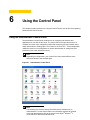
6
Using the Control Panel 53
Using the Administrator Control Panel 53
Managing Add-ons 55
Managing Certificates 57
Creating and Configuring Client Printers 58
Adding a Printer Using the WBT Printer Wizard 58
Editing Printer Properties 61
Selecting a Thin Client Desktop Option 62
Configuring DHCP Options 62
Using Edgeport for Port Expansion 64
Elo Touch 64
ELO Touch USB 65
Configuring Global ICA Settings 65
Configuring ICA Performance 68
Configuring Internet Settings 69
Configuring JETCET PRINT Settings 72
Setting the Language Option 73
Configuring Port Settings 74
Configuring the Rapport Agent 75
Configuring Remote Shadow 76
Configuring Security and Managing User Accounts 77
Adding a User Account 80
Modifying a User Account 81
Deleting a User Account 81
Managing Networks Using SNMP 81
Using the System Information Features 84
Using Administrator Tools 86
Managing TSC Licenses 88
Upgrading Thin Client Software 88
Managing USB Storage Devices Using USB Access 89
7
System Administration 91
About Updating Software 91
Using Wyse Device Manager Software for Remote Administration and Upgrades 92
Configuring the Thin Client for Automatic DHCP Firmware Upgrades 92
Performing FTP Pull Firmware Upgrades 94
Figures 97
1
Introduction
Wyse® WintermTM 3 series Thin Clients use Windows™ CE operating system. These thin
clients provide access to applications, files, and network resources made available on
machines hosting Citrix™ ICA and Microsoft™ RDP session services. Thin client
emulation software is installed locally by default. Other locally installed software permits
remote administration of the thin clients and provides local maintenance functions.
Session and network services available on enterprise networks may be accessed through
a direct Intranet connection, a dial-up server, or an ISP which provides access to the
Internet and thus permits the thin client to connect to an enterprise VPN (virtual private
network) server.
About this Guide
This guide is intended for administrators of the Wyse® WintermTM 3 series Thin Client. It
provides information and detailed system configurations to help administrators design and
manage a Wyse® WintermTM 3 series Thin Client environment.
Organization of this Guide
This guide is organized as follows:
Chapter 2, "Establishing a Server Environment," contains information on the network
architecture and enterprise server environment needed to provide network and session
services for Wyse® WintermTM 3 series Thin Clients. It also includes information to help
you to address important considerations when configuring access to the server
environment and when configuring the services to be provided by the server environment.
Chapter 3, "Configuring Basic Thin Client Settings," contains information on setting up the
basic functions for thin client use. It includes instructions for setting up a new thin client
and resetting a thin client to factory defaults.
Chapter 4, "Managing Connections," describes important connection features available for
you to use. It also provides instructions on using the administrator Desktop and
Connection Manger to manage the connections and applications you make available to
users.
Chapter 5, "Configuring Connections," contains information and detailed instructions on
setting up connections for selection and use by a thin client user.
Chapter 6, "Using the Control Panel," provides guidelines on using the Control Panel to
set-up thin client operating parameters and user accounts.
Chapter 7, "System Administration," contains information and detailed instructions to help
you manage your thin client environment through Wyse Device Manager Software, DHCP,
and FTP.
2
Chapter 1
Wyse Technical Support
To access Wyse technical resources, visit AskWyse.com. If you still have questions, you
can submit your questions using the Wyse Support Request Form, or call Customer
Support at 1-800-800-WYSE (toll free in U.S. and Canada). Hours of operation are from
7:00 am to 7:00 pm CST, Monday through Friday.
To access international support, visit http://www.wyse.com/global.
Related Online Resources Available at Wyse
Wyse® WintermTM 3 series Thin Client features can found in the Datasheet for your
specific thin client model. Datasheets are available on the Wyse Web site at:
http://www.wyse.com/serviceandsupport/support/documentindex.asp.
If you need to upgrade your CE .NET operating system, contact Wyse Customer Support
at: http://www.wyse.com/serviceandsupport.
The Users Guide: Wyse® WintermTM 3 series, Based on Microsoft® Windows® CE is
intended for users of the Wyse® WintermTM 3 series Thin Client. It provides detailed
instructions on using the thin client to manage the connections and applications available
to users from a network server. It is available at:
http://www.wyse.com/manuals.
The Add-on Administrators Guide: Wyse® WintermTM 3 series, Based on Microsoft®
Windows® CE is intended for administrators of the Wyse® WintermTM 3 series Thin Client.
It provides instructions on preparing for installing the Add-ons as well as obtaining and
verifying the Add-ons for the Wyse® WintermTM 3 series Thin Client. It also provides
detailed procedures for installing and removing the Add-ons. In addition, this guide
provides the Add-ons for Wyse® WintermTM 3 series Thin Client ReadMe documentation. It
is available at: http://www.wyse.com/manuals.
The Local Smart Card Administrators Guide: Wyse® WintermTM 3 series, Based on
Microsoft® Windows® CE is intended for administrators of the Wyse® WintermTM 3 series
Thin Client. It provides instructions on preparing to install the Local Smart Card Add-on as
well as instructions on obtaining and verifying the Add-on. It also provides detailed
procedures for installing, removing, and using the Add-on. It is available at:
http://www.wyse.com/manuals.
Wyse Thin Computing Software is available on the Wyse Web site at:
http://www.wyse.com/products/software.
2
Establishing a Server Environment
This chapter contains information on the network architecture and enterprise server
environment needed to provide network and session services for Wyse® WintermTM 3
series Thin Clients. It also includes information to help you to address important
considerations when configuring access to the server environment and when configuring
the services to be provided by the server environment.
Setting-Up Access to the Enterprise Servers
There are five basic methods of access to the enterprise server environment available to
the thin client. Except for Ethernet Direct, all of the access methods require that some
local settings be made on the thin client. These local settings are retained and are
available for the next thin client system start. Activating these local settings and the
defined connections can also be automated at thin client system start.
Methods of access include:
•
Ethernet Direct - This is a connection from the thin client Ethernet port directly to the
enterprise intranet. No additional hardware is required. In this configuration all network
services may be used, including the enterprise DHCP server. A DHCP server on the
network can provide not only the thin client IP address, but also the location of the file
server containing the software updates. For more information on DHCP, refer to "Using
Dynamic Host Configuration Protocol (DHCP)" and "Configuring DHCP Options."
•
Wireless Direct - A supported wireless adapter can be used to access the enterprise
intranet. A wireless adapter uses short-range wide-band radio to communicate with a
wireless access point. Typically, wireless access points are located at several locations
in the enterprise within range of the wireless adapters and directly connected to the
enterprise intranet. For more information on available wireless network devices and
wireless Add-on support available from Wyse, refer to the Add-on Administrators
Guide: Wyse® WintermTM 3 series, Based on Microsoft® Windows® CE.
•
PPPoE - Thin client support for PPPoE is intended for devices which connect to the
Internet directly from remote locations. The PPPoE Connection Wizard can be used
and is available from the desktop or the Connection Manager to configure and invoke
PPPoE connection to WAN. Once connected, all packets are through a PPP
connection over Ethernet to the DSL modem. For more information on the PPPoE
Connection Wizard, refer to "Creating and Configuring PPPoE Connections."
•
Dial-up Modem - A dial-up modem can be used with the thin client to access a dial-up
server. The dial-up server must be a Microsoft Remote Access Server or another
server that supports industry-standard protocols. The dial-up server can provide either
of the following methods of access to the enterprise intranet:
•
Direct access - An enterprise dial-up server directly connects to the enterprise
intranet.
•
Indirect access - An Internet Service Provider (ISP) dial-up server simply provides
access to the Internet, from which the thin client accesses an enterprise PPTP VPN
server that connects to the enterprise intranet.
4
Chapter 2
•
VPN (PPTP) - PPTP (Point-to-Point Tunneling Protocol) is a network protocol that
enables the secure transfer of data between a remote client (in this case the thin client)
and an enterprise server environment by creating a virtual private network (VPN)
across TCP/IP-based data networks such as the Internet. It provides a
password-protected path through the enterprise firewall to the enterprise server
environment in which the network and session services required by thin clients reside.
An Internet Service Provider (ISP) must be available to provide access to the Internet.
Any of the standard means of connecting to the ISP may be used, such as a dial-up
modem, cable modem, and DSL modem. The connection to the ISP must be
established first, before contacting the enterprise PPTP VPN server. This includes
dial-up access as well as direct access through the cable modem and DSL modem
paths. For more information on the VPN Connection Wizard, refer to "Creating and
Configuring VPN (PPTP) Client Connections."
Understanding the Network Services Used and Provided by the Thin
Client
Setting-up network services allows users to initiate connections to the enterprise servers
providing ICA, RDP and other services. Network services used by the thin client include
DHCP and FTP file services, DNS, and LPD.
Note
The thin client can act as an LPR client and use the LPD services provided
by other nodes on the network. In addition, the thin client can act as an LPD
server and provide print services to other nodes on the network.
Using Dynamic Host Configuration Protocol (DHCP)
A thin client is initially configured to obtain its IP address and network configurations from
a DHCP server (new thin client or a thin client reset to default configurations). A DHCP
server can also provide the IP address or DNS name of the FTP server and the FTP
root-path location of the upgrade images for access through the DHCP upgrade process.
Using DHCP to configure and upgrade thin clients saves you the time and effort needed to
complete these processes locally on multiple thin clients.
Note
If a particular thin client is to function as an LPD print server, it should be
assigned a fixed IP address. However, you can also guarantee that an LPD
server will get the same IP address every time by making a reservation for
that thin client in the DHCP server. In that way, you can preserve the
stateless nature of the thin client and still guarantee a fixed address for the
server. In fact, you can assign a symbolic name to the reservation address
so that other thin clients can reference the LPD server by name rather than
by static IP address (the symbolic name must be registered with a DNS
server before other thin clients will be able to locate this LPD server). The
thin client does not dynamically register its name and the DNS registration
must be manual.
5
Establishing a Server Environment
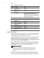
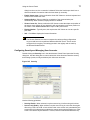
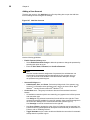
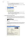
The DHCP options listed in Table 1 are accepted by the thin clients. For more information
on configuring the DHCP Options dialog box, refer to "Configuring DHCP Options."
Note
Use of DHCP is recommended. If a DHCP server is not available, fixed IP
addresses can be assigned (this does, however, reduce the stateless
functionality of the thin clients) and must be entered locally for each device.
Table 1
DHCP Options
Option
Description
Notes
1
Subnet Mask
Required.
3
Router
Optional but recommended. It is not required
unless the thin client must interact with servers
on a different subnet.
6
Domain Name Server
(DNS)
Optional but recommended.
12
Hostname
Optional.
15
Domain Name
Optional but recommended.
43
Vendor Class Specific
Information
Optional. The thin client will interpret this
information only if the Interpret Vendor Class
Info check box is selected in the DHCP Options
dialog box.
50
Requested IP
Required.
51
Lease Time
Required.
52
Option Overload
Optional.
53
DHCP Message Type
Required.
54
DHCP Server IP Address
Recommended.
55
Parameter Request List
Sent by thin client.
57
Maximum DHCP Message
Size
Optional (always sent by thin client).
58
T1 (renew) Time
Required.
59
T2 (rebind) Time
Required.
61
Client identifier
Always sent.
155
Remote Server IP Address
or name
Optional.
156
Logon User Name used for
a connection
Optional.
157
Domain name used for a
connection
Optional.
158
Logon Password used for a
connection
Optional.
6
Chapter 2
Table 1
DHCP Options, Continued
Option
Description
Notes
159
Command Line for a
connection
Optional.
160
Working Directory for a
connection
Optional.
161
FTP server list
Optional string. Can be either the name or the
IP address of the FTP server where the
updated thin client image is stored. If a name is
given, the name must be resolvable by the DNS
server(s) specified in Option 6.
162
Root path to the FTP files
Optional string.
163
SNMP Trap server IP
Address list
Optional.
164
SNMP Set Community
Optional.
165
RDP startup published
applications
Optional.
166
Terminal Emulation Mode
Optional.
167
Terminal Emulation ID
Optional.
168
Name of the server for the
virtual port
Optional.
Using FTP File Servers
Upgrade images used by the DHCP upgrade and FTP Pull Firmware upgrade processes
are stored on the FTP server in a directory in the FTP root path (this server name and
root-path directory must be made available to the thin client).
If Automatic DHCP upgrades are used, these items must be entered in the server DHCP
Options. The DHCP values to use are located in Table 1, "DHCP Options" and are
configured in the DHCP Options dialog box (defaults are 161 and 162, respectively). The
FTP server must provide anonymous log-on capability. For more information on the DHCP
Options dialog box, refer to "Configuring DHCP Options."
If FTP Pull Firmware upgrades are used, these items must be entered in the Upgrade
dialog box on the thin client, along with the Login name and password (the default name
and password are both anonymous). For more information on the FTP Pull Firmware
upgrade process, refer to "Performing FTP Pull Firmware Upgrades."
Note
Params.ini, Bootstrap212.exe, and the Bin file along with the update
firmware must be present on your FTP server to upgrade the thin client.
Upgrade software packages can be obtained through Wyse customer
support.
When the thin client boots, it accesses the software update images from the FTP file
server. The FTP file server and path to the update files are available through DHCP
vendor options 161 and 162 (see "Using Dynamic Host Configuration Protocol (DHCP)").
Establishing a Server Environment
7
Using DNS
Thin clients accept valid DNS names registered on a DNS server available to the
enterprise intranet. The thin client will query a DNS server on the network for name to IP
resolution. In most cases DNS is not required but may be used to allow hosts to be
accessed by their registered DNS names rather than their IP addresses. Every Windows
DNS server in Windows 2000 and later includes Dynamic DNS (DDNS) and every server
registers dynamically with the DNS server. However, the thin client does not do dynamic
registration and therefore, requires a static or non-variant IP address and manual DNS
registration in order to provide LPD support by name (for example, in the case where the
thin client is used as an LPD printer server). For DHCP entry of DNS domain and server
location information, refer to "Using Dynamic Host Configuration Protocol (DHCP)."
Configuring and Providing Line Printer Daemon (LPD) Services
A thin client can be configured to provide Line Printer Daemon (LPD) services (making the
thin client a printer server receiving print jobs from one or more clients and spooling these
jobs to a designated physical port). The LPD server receives print jobs sent to a named
line printer queue from the LPR client and prints them on the designated printer.
For more information on LPD configuration, refer to the Users Guide: Wyse® WintermTM 3
series, Based on Microsoft® Windows® CE.
A thin client can also be configured as an LPR client. LPR is a component of the Line
Printer Daemon Protocol. LPR is a client sending a print job to a server. LPR works in
conjunction with the Line Printer Daemon (LPD) server by assigning a print job to a named
line printer queue managed by the LPD server. The LPD is a server receiving print tasks
from one or more clients and spooling these jobs to a physical port.
For more information on LPR configuration, refer to the Users Guide: Wyse® WintermTM 3
series, Based on Microsoft® Windows® CE.
Understanding Session Services
Thin-client session services are made available by servers hosting Citrix ICA and
Microsoft RDP software products.
Independent Computing Architecture (ICA) is a three-tier, server-based computing
technology that separates the logic of an application from its user interface. The ICA client
software installed on the thin client allows the user to interact with the application GUI,
while all of the application processes are executed on the server. For information on
configuring ICA, refer to "Configuring ICA Session Services."
Using the ICA Program Neighborhood Agent (PNAgent) in conjunction with NFuse Classic
or the Web Interface, you can integrate published resources with user desktops. Users
access remote applications, desktops, and content by clicking icons on their Windows
desktop or in the Start menu.
The PNAgent includes the following functions:
•
User authentication - The thin client presents user credentials to the MetaFrame XP
server when users try to connect and, if configured to do so by you the administrator,
every time users launch published resources.
•
Application and content enumeration - The thin client presents users with their
individual set of published resources.
•
Application launching - The thin client is the local engine used to launch published
applications.
8
Chapter 2
•
Desktop integration - The thin client integrates a user set of published resources with
that user desktop.
•
User preferences - The thin client validates and implements local user preferences.
For more information on the configuring ICA session services, refer to "Configuring ICA
Session Services."
For more information on the PNAgent, refer to "Configuring and Using the PNAgent."
Note
The ICA server must be licensed from Citrix Systems, Inc. You must
purchase enough client licenses to support the total concurrent thin client
load placed on the Citrix server farm. A failure to connect when all client
seats are occupied does not represent a failure of Wyse equipment. The ICA
client software is installed on the thin client.
Remote Desktop Protocol (RDP) is a network protocol that allows a thin client to
communicate with the Terminal Server or Windows 2000/2003 Server with Terminal
Services over the network. This protocol is based on the T.120 protocol suite, an
international standard multi-channel conferencing protocol. The thin client supports RDP
version 5.x. For information on configuring RDP, refer to "Configuring RDP Session
Services."
Configuring ICA Session Services
ICA session services can be made available on the network using either of the following
services:
•
Windows 2000 or 2003 Server with Terminal Services and one of the following
installed:
•
Citrix MetaFrame XP
•
Citrix Presentation Server
Use the instructions accompanying these products to install them and make sessions and
applications available to the thin clients sharing the server environment.
Note
If a Windows 2000 or 2003 Server is used, a Terminal Services Client
Access License (TSCAL) server must also reside somewhere on the
network. The server will grant a temporary (90-day) license on an individual
device basis. Beyond the temporary (90-day) license, you must purchase
TSCALs and install them on the TSCAL server (you will not be able to make
a connection without a temporary or permanent license).
Establishing a Server Environment
9
Configuring and Using the PNAgent
The Program Neighborhood Agent (PNAgent) allows users to connect (without using a
Web browser) to a server running the Web interface and access all published applications
in the server farm. Users do not have to manually configure a connection to each
application as they do with the Connection Manager. The PNAgent also provides single
sign-on. That is, when users logon at the start of a session, they do not need to use logon
credentials again during that session (even if they connect to different applications).
Use the following guidelines for configuring and using the PNAgent:
•
Ensure that the configuration file on the server has suitable settings for users. Use the
Program Neighborhood Agent Administration tool to check the default settings and
change them if necessary. For procedures on configuring the settings on the server,
refer to "Configuring PNAgent Settings on the Web Interface Server."
•
Users who wish to connect using the PNAgent must then enable it on their thin client
(users can also customize their settings). For procedures on enabling and customizing
the PNAgent on the thin client, refer to the Users Guide: Wyse® WintermTM 3 series,
Based on Microsoft® Windows® CE.
Once users have the settings they require, they connect to the server, are prompted to
authenticate, and are presented with a list of the available applications.
Note
Connections will be populated in the thin client Connection Manager (if the
Standard Desktop UI option is selected) or to the user desktop (if the New
Desktop option is selected). For information on selecting a desktop option,
refer to "Selecting a Thin Client Desktop Option."
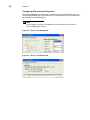
Configuring PNAgent Settings on the Web Interface Server
The PNAgent configuration settings are stored on the server in a file called Config.xml.
Administrators can edit this file using the Program Neighborhood Administration tool
(Admin tool), which provides an easy-to-use interface to the file parameters.
Caution
The settings in the configuration file are global. Therefore, the settings and
any changes you make to them affect all users connecting to the file.
You can modify the default settings for all users, and can allow or deny users the ability to
do any of the following:
•
Select their own options for an ICA connection.
•
Change their connection to a different server URL.
When a user enables the PNAgent on the thin client and connects to the server URL, the
thin client reads the configuration data from the server. The settings configured using the
Admin tool affect all users of this configuration file. The options and their settings are
displayed in the thin client.
To access the PNAgent Admin tool, connect to the following URL on the server running
the Web interface:
http://servername/Citrix/PNAgentAdmin/
The PNAgent Admin tool enables you to specify:
•
Which tabs users see in their Global ICA Client Settings dialog box - Users can see a
maximum of two tabs in the Global ICA Client Settings dialog box. The Options tab (to
select the preferences for a session) and Server tab (to select the server URL to which
10
Chapter 2
they want to connect). To hide or display a tab, use the Client Tab Control option in the
PNAgent Admin tool to make the configurations. Note that to hide or display the
Options tab, administrators must use Session Options within the Client Tab Control
option.
•
Server connections - To specify the URL to which users can connect, use the Server
Settings option in the PNAdmin tool.
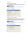
Configuring RDP Session Services
RDP session services can be made available on the network to allow you to connect
remotely to a desktop computer running Microsoft Windows NT®, Windows 2000,
Windows 2003, and Windows XP Professional, or a server running Microsoft® Windows
NT® Server 4.0, Terminal Server Edition. The Remote Desktop Protocol allows a thin
client to execute Windows applications within a Windows graphical user interface (GUI)
environment, even though they are actually being executed on the server
Use the instructions accompanying these products to install them and make sessions and
applications available to the thin clients sharing the server environment.
Note
If a Windows 2000 or 2003 Server is used, a Terminal Services Client
Access License (TSCAL) server must also reside somewhere on the
network. The server will grant a temporary (90-day) license on an individual
device basis. Beyond the temporary (90-day) license, you must purchase
TSCALs and install them on the TSCAL server (you will not be able to make
a connection without a temporary or permanent license).
3
Configuring Basic Thin Client
Settings
This chapter contains information on setting up the basic functions for thin client use. It
includes instructions for setting up a new thin client and resetting a thin client to factory
defaults.
Note
The password for the BIOS is Fireport.
Setting Up the Thin Client for the First Time
The first time a new thin client (or a thin client reset to factory-defaults) starts, the thin
client will log on automatically as an administrator (with no password required). You can
use the Setup Wizard to configure the settings necessary for basic operation and access
to the network resources needed for remote administration. For information on the Setup
Wizard, refer to "Using the Setup Wizard."
Note
You must enable security for login requirements to be active, otherwise, the
thin client automatically logs on as an administrator with no password
required. For more information on enabling security, refer to "Configuring
Security and Managing User Accounts."
After basic configurations, you can continue thin client configurations either locally or
remotely:
•
Local Setup - Manually (by you as an administrator) on each thin client. Depending on
the number of thin clients, this method can be time consuming as there are many
configurations available for each individual thin client on the network. For more
information on local configurations, refer to "Using the Desktop and Connection
Manager to Manage Connections" and "Using the Control Panel."
•
Remote Setup - By using Wyse Device Manager software (formally Rapport Remote
Administration Software) or SNMP tools you can configure and manage thin clients
remotely. Typically, a single thin client would be configured locally, and then the remote
software tools would be used to extract the settings into a database for broadcast as
an upgrade to other thin clients on the network. For information on remote
administration and software upgrades, refer to "System Administration." For
information on SNMP, refer to "Managing Networks Using SNMP."
12
Chapter 3
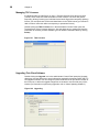
Using the Setup Wizard
The Setup Wizard allows you to quickly configure basic thin client settings (so that the thin
client is configured for network users and available for remote administration). Some
wizard dialog boxes are informational and require no user input, while other dialog boxes
prompt you for required information.
To reset the thin client to factory defaults and then use the Setup Wizard to configure
basic thin client settings, begin at step 1; to use the Setup Wizard to configure basic thin
client settings on a new thin client first boot, begin at step 5:
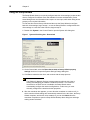
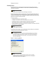
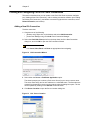
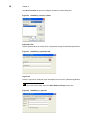
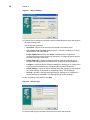
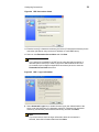
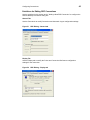
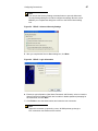
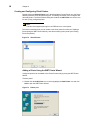
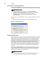
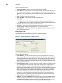
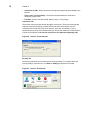
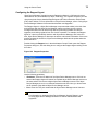
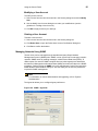
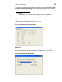
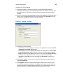
1. Double-click System in the Control Panel to open the System Info dialog box.
Figure 1
System Info dialog box - General tab
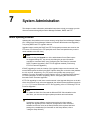
2. On the General tab, select the Reset the terminal to factory-default property
settings check box to open the System Settings Change dialog box.
3. Click Yes to restart the thin client, and continue with the setup process.
Note
The Waiting for Network Services message appears while the thin client is
starting and attempting to establish a network connection. If no network is
connected or no DHCP server is available, the Setup Wizard cannot
automatically configure the network configurations. In this case, you must
manually configure the network and other properties.
4. After the countdown box appears, you can allow the countdown to continue to 0 (in
which case the default settings are automatically selected for the thin client, the Setup
Wizard completes, and the thin client restarts) or you can click Next before the
countdown completes to open the Setup Wizard Desktop Area dialog box and begin
making custom selections.
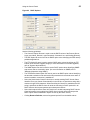
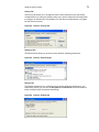
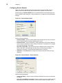
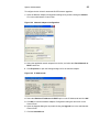
Configuring Basic Thin Client Settings
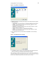
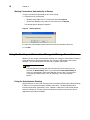
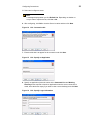
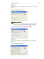
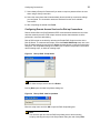
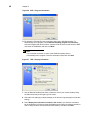
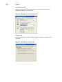
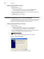
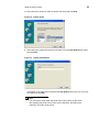
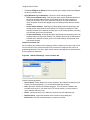
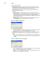
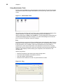
Figure 2
13
Setup Wizard - Desktop Area
5. Double-click an item in the Desktop Area dialog box and configure that item using the
following guidelines:
•
Client Printers - Use the procedures in "Creating and Configuring Client Printers."
•
Display - Use the procedures in the Users Guide: Wyse® WintermTM 3 series,
Based on Microsoft® Windows® CE.
•
Keyboard - Use the procedures in the Users Guide: Wyse® WintermTM 3 series,
Based on Microsoft® Windows® CE.
•
Internet - Use the procedures in "Configuring Internet Settings."
•
Network - Use the procedures in the Users Guide: Wyse® WintermTM 3 series,
Based on Microsoft® Windows® CE.
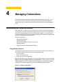
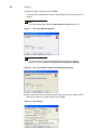
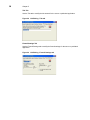
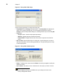
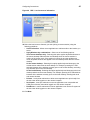
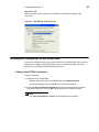
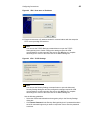
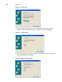
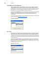
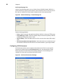
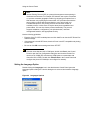
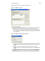
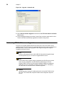
6. After configuring the items you want and then clicking Next, a success message
displays.
Figure 3
Setup Wizard success message
7. Click Finish to apply the settings, close the Setup Wizard, and restart the thin client
(the thin client will log on automatically with administrator privileges).
After completing the wizard and restarting the thin client, the initial setup is complete. As
discussed in "Setting Up the Thin Client for the First Time." any future changes to settings
that were made using the Setup Wizard can be made locally or remotely.
14
Chapter 3
This page intentionally blank.
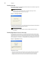
4
Managing Connections
This chapter describes important connection features available for you to use. It also
provides instructions on using the administrator Desktop and Connection Manger to
manage (add, edit, and delete) the connections and applications you make available to
users.
Understanding the Connection Features
How a user logs in and what they see after they log in, depends on your configurations.
For example, a username and password may be required to log in to a thin client or the
thin client may automatically log on when started. After logging in, a user may see the
Connection Manager dialog box or the windows desktop (or if configured, an application or
connection may be launched automatically).
This section discusses:
•
"Using Multiple Sessions"
•
"Enabling AutoLogin"
•
"Enabling Single Button Connect for User Login"
•
"Enabling Failover"
•
"Starting Connections Automatically at Startup"
Using Multiple Sessions
The Multiple Sessions feature allows the thin client to have multiple active connections.
The number of active connections you can have depends on the:
•
amount of RAM.
•
types of connections open.
•
number of connections configured.
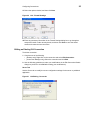
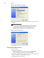
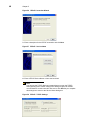
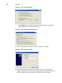
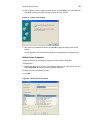
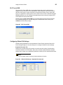
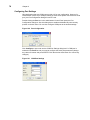
With the New Desktop (see "Selecting a Thin Client Desktop Option") you can also select
Support launching multiple instances on new Desktop to enable support for opening
multiple instances of one ICA or RDP connection (supported for published applications
configured as a Seamless Windows Connection or PNAgent enabled sessions).
Figure 4
Desktop Configuration
16
Chapter 4
Enabling AutoLogin
The AutoLogin feature is an automatic login function that uses a countdown to login to the
thin client (for example, 5 seconds).
Note
If you also want to automatically make a connection upon log-in, refer to
"Enabling Single Button Connect for User Login."
Figure 5
AutoLogin countdown
To enable the AutoLogin feature, use the administrator Security dialog box as described in
"Configuring Security and Managing User Accounts."
Note
Since AutoLogin is a global function, it does not matter what other functions
are enabled.
Enabling Single Button Connect for User Login
The Single Button Connect feature is an automatic login function that uses the Connect
command button to allow users to login to the thin client (and if configured, automatically
makes a connection upon log-in). To enable Single Button Connect, use the administrator
Security dialog box. as described in "Configuring Security and Managing User Accounts."
Figure 6
Single Button Connect
Single Button Connect:
•
Logs a user into their thin client using the account to which AutoLogin is associated.
•
Connects to the first connection in the Connections Name list of the Connection
Manager (unless another connection in the list has been made with Autostart).
Managing Connections
17
Enabling Failover
The Failover feature is a connection function that causes the thin client to ping the
intended device (to determine whether or not the device is available) before making a
connection to the device.
Note
Failover does not support Serial and PNAgent connections.
Packet Internet Groper (Ping) is a network utility. It tests communication with nodes in a
network by sending packets to each selected node. Ping then waits to receive the echo
response from that selected node. If pinging the intended connection fails, the thin client
pings each successive connection in the list.
For each connection:
•
If a ping is successful, the connection is made.
•
If a ping is not successful, the thin client pings the next connection.
•
A ping does not work on a serial connection. Failover will not continue after
encountering a serial connection, but will launch the serial connection.
•
If failover pings all the connections in the list and a connection is not made, the function
stops and an error message displays.
Note
Failover skips IE connections.
To enable the Failover feature, use the administrator Security dialog box as described in
"Configuring Security and Managing User Accounts."
Note
If the Verbose check box is selected on the Security dialog box, the Failover
Log Window displays when failover is finished. The Failover Log Window is a
list of all the connections that were pinged. The list reports both successful
and unsuccessful pings.
Figure 7
Failover Log Window
Note
Failover is global and wholly automatic to the thin client. It will work
regardless of what connection you are trying to make, or what type of
account under which you are logged in.
18
Chapter 4
Starting Connections Automatically at Startup
To start a connection automatically at thin client startup:
1. Complete one of the following:
•
(Desktop only) Right-click on a connection and select Options.
•
(Connection Manager only) Select a connection and click Startup.
The Startup Options dialog box appears.
Figure 8
Startup Options
2. Select the Automatically start the selected connection at startup check box.
3. Click OK.
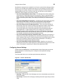
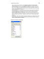
Using the Desktop and Connection Manager to Manage Connections
Whether you are using the administrator Desktop (see "Using the Administrator Desktop")
or the administrator Connection Manager (see "Using the Administrator Connection
Manager"), only an administrator can add, edit, or delete connections.
Note
The Administrator Desktop (with icons and menus) can be used only if you
selected the New Desktop option. If you selected the Standard Desktop UI
option, the Administrator Connection Manager can be used. For information
on selecting a desktop option, refer to "Selecting a Thin Client Desktop
Option."
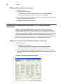
Using the Administrator Desktop
Wyse® WintermTM 3 series Thin Clients provide a windows interface option (New Desktop)
in which you can open and manage multiple connections. The New Desktop option
includes connections, applications, icons, a taskbar, a Start menu, and several related
features. It allows you to easily create and manage connections and use the various
applications and features available.
Managing Connections
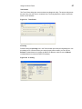
Figure 9
19
Administrator Desktop example
Note
The Start menu allows quick and easy access to all programs and settings
available, as well as shutting down the thin client. For example, to open the
Control Panel window, click Start | Settings | Control Panel. For information
about the administrator Control Panel, refer to "Using the Administrator
Control Panel."
Use the following guidelines:
•
To start connections you can double-click an icon, right-click an icon and select Open,
or use the Start menu.
•
To start a Control Panel application, double-click the application icon.
•
Desktop icons can easily be arranged by name, type, and so on by right-clicking on the
desktop and using the menu provided.
•
You can toggle between active connections using the taskbar (click on an open
connection) or by using the Alt+Tab key combination (for details on these and other
taskbar features, refer to the Users Guide: Wyse® WintermTM 3 series, Based on
Microsoft® Windows® CE).
•
To delete a connection, right-click on a connection, select Delete Connection, and
confirm the deletion by clicking Yes.
•
To add or edit a connection, refer to the following guidelines for the connection you
want:
•
"Creating and Configuring Citrix ICA Client Connections"
•
"Creating and Configuring Dial-Up Client Connections"
•
"Creating and Configuring Ericom PowerTerm Terminal Emulator Connections"
•
"Creating and Configuring Internet Explorer Connections"
•
"Creating and Configuring Microsoft Remote Desktop Client Connections"
•
"Creating and Configuring PPPoE Connections"
•
"Creating and Configuring VPN (PPTP) Client Connections"
20
Chapter 4
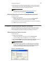
Using the Administrator Connection Manager
The Connection Manager allows you to create and manage multiple connections, and use
the various applications and features available.
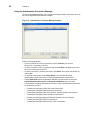
Figure 10
Administrator Connection Manager example
Use the following guidelines:
•
To start a connection, select a connection and click Connect (you can also
double-click a connection in the list).
•
To end a connection, select a connection and click End (End is enabled when one or
more connections become active).
•
To delete a connection, select a connection, click Delete, and confirm the deletion by
clicking Yes.
•
To open the Control panel, click Control Panel. For information about the
administrator Control Panel, refer to "Using the Administrator Control Panel."
•
Clicking Shut Down opens the Shutdown Window. Use this window to select the
Logout, Shutdown the terminal, or Shutdown and Restart option you want.
•
For information on adding and editing a connection, refer to the detailed procedures for
the connection you want:
•
"Creating and Configuring Citrix ICA Client Connections"
•
"Creating and Configuring Dial-Up Client Connections"
•
"Creating and Configuring Ericom PowerTerm Terminal Emulator Connections"
•
"Creating and Configuring Internet Explorer Connections"
•
"Creating and Configuring Microsoft Remote Desktop Client Connections"
•
"Creating and Configuring PPPoE Connections"
•
"Creating and Configuring VPN (PPTP) Client Connections"
5
Configuring Connections
This chapter contains information and detailed instructions on setting up connections for
selection and use by a thin client user.
This section discusses:
•
"Creating and Configuring Citrix ICA Client Connections"
•
"Creating and Configuring Dial-Up Client Connections"
•
"Creating and Configuring Ericom PowerTerm Terminal Emulator Connections"
•
"Creating and Configuring Internet Explorer Connections"
•
"Creating and Configuring Microsoft Remote Desktop Client Connections"
•
"Creating and Configuring PPPoE Connections"
•
"Creating and Configuring VPN (PPTP) Client Connections"
Note
Whether you are using the administrator Desktop (New Desktop option) or
the administrator Connection Manager (Standard UI option), you will use the
New Connection dialog box to add new connections.
Figure 11
New Connection dialog box
22
Chapter 5
Creating and Configuring Citrix ICA Client Connections
This section describes how you can create a new Citrix ICA Client connection definition
(see "Adding a New ICA Connection"), edit an existing connection definition (see "Editing
an Existing ICA Connection"), and delete a connection (right-click the connection, select
Delete Connection, and confirm).
Adding a New ICA Connection
To add a connection:
1. Complete one of the following:
•
(Desktop only) Right-click on the desktop and select Add Connection.
•
(Connection Manager only) Click Add in the Connection Manager.
2. Select the Citrix ICA Client option from the drop-down list of the New Connection
dialog box, and click OK to open the ICA Connection Wizard.
Note
Use Cancel, Next, Back, and Done as appropriate when navigating.
Figure 12
ICA Connection Wizard
3. Select either the Server or Published Application option.
The wizard prompts you to select a Citrix server from a list or to enter a server name.
The server name entry can be an IP address or a valid DNS name. The list entries are
created from browsing for servers on the network when the dialog box opens. The list
can be updated by clicking on the Refresh command button.
4. Click Server Location to open the Server Location dialog box.
Figure 13
ICA - Server Location
Configuring Connections
5. Select and configure a server.
Note
A message displays when you click Default List. Depending on whether or
not you want to replace the list, click Yes or No.
6. After configuring, click OK to close the Server Location and then click Next.
Figure 14
ICA - Connection title
7. Enter the title that is to appear for the connection and click Next.
Figure 15
ICA - Specify an Application
8. Specify an application (make the entries in the Command Line and Working
Directory boxes required to launch an application when the server connection is
made; leave the boxes empty if you want to view a server desktop) and click Next.
Figure 16
ICA - Specify Logon Information
23
24
Chapter 5
9. Specify the logon information and click Next.
The information in this dialog box may be required by the server before access is
granted.
Note
If you use a Smart Card, select the Allow Smart Card logon check box.
Figure 17
ICA - Select Window Options
Note
You can configure a new published application connection for seamless
windows by selecting View in a separate window (Seamless Window).
Figure 18
ICA - Select Window Options with Seamless Windows
10.Select the Window Colors options (a smaller color option results in faster network
speed at the expense of display quality) and click Next.
Figure 19
ICA - Options
Configuring Connections
25
11. Select the options desired, and then click Next.
Figure 20
ICA - Firewall Settings
12.Enter any necessary information in the Firewall Settings dialog box to go through an
enterprise firewall or other security barrier, and then click Done to save the wizard
entries and create the new connection.
Editing an Existing ICA Connection
To edit the connection:
1. Complete one of the following:
•
(Desktop only) Right-click on the connection and select Edit Connection.
•
(Connection Manager only) Select the connection and click Edit.
2. Use the following guidelines to make your modifications in the Edit Connection Details
dialog box (be sure to click OK after making your modifications):
Server Tab
Use the Server tab to modify the server configuration settings for the server or published
application.
Figure 21
ICA Editing - Server tab
26
Chapter 5
Use Server Location to open and configure the Server Location dialog box.
Figure 22
ICA Editing - Server Location
Application Tab
Use the Application tab to modify server configuration settings for published applications.
Figure 23
ICA Editing - Application tab
Logon Tab
Use the Logon tab to modify the logon information for the server or published application.
Note
If you use a Smart Card, select the Allow Smart Card logon check box.
Figure 24
ICA Editing - Logon tab
Configuring Connections
Window Tab
Use the Window tab to modify the Window Colors option for the server or published
application.
Figure 25
ICA Editing - Window tab
Note
You can configure an existing published application connection for seamless
windows by selecting View in a separate window (Seamless Window).
Figure 26
ICA Editing - Window tab with Seamless Windows
Options Tab
Use the Options tab to modify the supported options for the server or published
application.
Figure 27
ICA Editing - Options tab
27
28
Chapter 5
Title Tab
Use the Title tab to modify the title entered for the server or published application.
Figure 28
ICA Editing - Title tab
Firewall Settings Tab
Use the Firewall Settings tab to modify the firewall settings for the server or published
application.
Figure 29
ICA Editing - Firewall Settings tab
Configuring Connections
29
Creating and Configuring Dial-Up Client Connections
This section describes how you can create a new Dial-up Client connection definition (see
"Adding a New Dial-up Connection"), and edit an existing connection definition (see
"Editing an Existing Dial-up Connection").
Adding a New Dial-up Connection
To add a connection:
1. Complete one of the following:
•
(Desktop only) Right-click on the desktop and select Add Connection.
•
(Connection Manager only) Click Add in the Connection Manager.
2. Select the Dial-up Client option from the drop-down list of the New Connection dialog
box, and click OK to open the Dial-Up Configuration Wizard.
Note
Use Cancel, Next, Back, and Done as appropriate when navigating.
Figure 30
Dial-up description
3. Enter the name that is to appear for the connection and click Next.
Note
The Dial-up invalid massage is displayed if Next is clicked with an empty
description box or invalid characters (<>()[]//\.*?:”,|) entered in the description
box.
30
Chapter 5
Figure 31
Dial-up Settings
4. Enter the Dial-up settings by using the wizard command buttons to open and configure
the various dialog boxes.
Use the following guidelines:
•
Serial Port - Use the list to select the access path to the dial-up server.
•
Use Country Code and Area Code check box - If selected, enables you to enter
these codes for use when dialing.
•
Enable RAS Script check box and Script command button - Enables and
configures Remote Access Services as discussed in "Configuring Remote Access
Services for Dial-up Connections."
•
Dialing Properties - Opens the Dialing Properties dialog box, allowing you to
configure the dialing properties as discussed in "Configuring Dialing Properties."
•
Configure - Opens the Device Properties dialog box, allowing you to configure the
device properties as discussed in "Configuring Dial-up Device Properties."
•
TCP/IP Settings - Opens the TCP/IP Settings dialog box, allowing you to configure
the TCP/IP settings as discussed in "Configuring Dial-up TCP/IP Settings."
•
Security - Opens the Security Settings dialog box, allowing you to configure the
security settings as discussed in "Configuring Dial-up Security Settings."
5. After completing configurations, click Next.
Figure 32
Dial-up Login
6. Enter the dial-up login information required to access the dial-up server.
Configuring Connections
31
7. Select Always Prompt for Password if you want to require a password from the user
when using a dial-up connection.
8. Select the connections that will automatically launch the dial-up connection settings
you configured. The connection names are obtained from the list of available
connections.
9. After completing the wizard click Finish.
Configuring Remote Access Services for Dial-up Connections
Remote Access Services (RAS) facilitates PPP communications between the thin client
and other network protocols. RAS scripts automate actions that otherwise would be
performed in text mode after dialing.
Dial-up RAS scripts are enabled by selecting the Enable RAS Script check box in the
Dial-up Wizard. To create and edit scripts, select the Enable RAS Script check box in the
Dial-up Settings dialog box and click the Script command button to open the Script Name
dialog box. The Script Name dialog box enables you to create a script under a new name,
edit an existing script, or delete an existing script.
Figure 33
Dial-up RAS - Script Name
Note
To delete a script, select it and click Delete.
Clicking New opens the New Script Name dialog box.
Figure 34
Dial-up RAS - New Script Name
Enter the script name and click OK to open the RAS Script dialog box.
Note
You can also open and use the RAS Script dialog box to edit an existing
script by selecting the script in the Script Name dialog box and clicking Edit.
32
Chapter 5
Figure 35
Dial-up RAS - RAS Script
Use the following guidelines to configure the dialog box:
•
Script Name box and Change command button - The Script Name box displays the
name of the currently selected script. You can change the selection by clicking
Change to open the Script Name dialog box, selecting another script, and clicking OK.
•
Script area:
•
·
Script text area - Lists the script input/output strings:
·
Wait For - Displays strings received from the host.
·
Respond With - Displays what the thin client sends in response to the Wait For
string.
New and Edit - Open the Edit Script Line dialog box. Use this dialog box to create a
new line in the script or edit an existing (selected) line. The specific scripts are unique
to each target system.
Figure 36
Dial-up RAS - Edit Script Line
•
Delete - To delete a line, select it and click Delete. You will be prompted to confirm the
deletion of the line.
•
Up and Down - Use these to move a selected line in the script up or down in the list.
Note
After configuring, be sure to click OK to save your settings and return to the
Dial-Up Configuration Wizard.
Configuring Connections
33
Configuring Dialing Properties
Clicking the Dialing Properties command button in the Dial-up Settings dialog box of the
Dial-Up Configuration Wizard opens the Dialing Properties dialog box. Use this dialog box
to configure the dialing settings indicated in the dialog box.
Note
Refer to the modem instruction manual for information to configure the
Dialing Patterns area.
Figure 37
Dial-up - Dialing Properties
Note
After configuring, be sure to click OK to save your settings and return to the
Dial-Up Configuration Wizard.
34
Chapter 5
Configuring Dial-up Device Properties
Clicking the Configure command button in the Dial-Up Configuration Wizard opens the
Device Properties dialog box. Use this dialog box to configure the device properties for the
Port Settings and Call Options tabs.
Note
After configuring, be sure to click OK to save your settings and return to the
Dial-Up Configuration Wizard.
Figure 38
Dial-up - Port Settings tab
Figure 39
Dial-up - Call Options tab
Configuring Connections
35
Configuring Dial-up TCP/IP Settings
Clicking the TCP/IP Settings command button in the Dial-Up Configuration Wizard opens
the TCP/IP Settings dialog box. Use this dialog box to configure the TCP/IP settings.
Note
After configuring, be sure to click OK to save your settings and return to the
Dial-Up Configuration Wizard.
Figure 40
Dial-up - TCP/IP Settings
Configuring Dial-up Security Settings
Clicking the Security command button in the Dial-Up Configuration Wizard opens the
Security Settings dialog box. Use this dialog box to configure the security settings. Select
the Authentication and encryption policy option you want. You can click Unsave
password to ensure that a user password is not stored locally for this connection.
Note
After configuring, be sure to click OK to save your settings and return to the
Dial-Up Configuration Wizard.
Figure 41
Dial-up - Security Settings
36
Chapter 5
Editing an Existing Dial-up Connection
To edit the connection:
1. Complete one of the following:
•
(Desktop only) Right-click on the connection and select Edit Connection.
•
(Connection Manager only) Select the connection and click Edit.
2. Use the Dial-Up Configuration Wizard to make your modifications (use the guidelines
in "Adding a New Dial-up Connection").
3. Click OK to apply and save your settings.
Creating and Configuring Ericom PowerTerm Terminal Emulator
Connections
PowerTerm WBT Terminal Emulator is used by the thin client for running legacy
character-based applications on remote computers. You can set up a wide variety of
connections that a user can open. The host computers are accessed through TCP/IP
network, dial-up modem, or serial port. This section describes how you can create a new
Ericom PowerTerm Terminal Emulator connection definition (see "Adding an Ericom
PowerTerm Terminal Emulation Connection"), and edit an existing connection definition
(see "Editing an Existing Ericom PowerTerm Terminal Emulation Connection").
Adding an Ericom PowerTerm Terminal Emulation Connection
To add a connection:
1. Complete one of the following:
•
(Desktop only) Right-click on the desktop and select Add Connection.
•
(Connection Manager only) Click Add in the Connection Manager.
2. Select the Ericom PowerTerm Terminal Emulator option from the list in the New
Connection dialog box, and click OK to open the PowerTerm Connection Properties
dialog box.
Figure 42
PowerTerm Connection Properties
Configuring Connections
3. Use the PowerTerm Connections Properties dialog box to set up a wide variety of
connections that a user can open. Note that availability of the boxes and options
change according to your connection configuration selections.
Note
For complete information on configuring the dialog box, refer to the
PowerTerm online documentation at: http://www.ericom.com.
Editing an Existing Ericom PowerTerm Terminal Emulation Connection
To edit the connection:
1. Complete one of the following:
•
(Desktop only) Right-click on the connection and select Edit Connection.
•
(Connection Manager only) Select the connection and click Edit.
2. Use the PowerTerm Connections Properties dialog box to make your modifications.
3. Click OK to apply and save your settings.
Creating and Configuring Internet Explorer Connections
This section describes how you can create a new Internet Explorer (IE) connection
definition (see "Adding a New Internet Explorer Connection"), and edit an existing
connection definition (see "Editing an Existing Internet Explorer Connection").
Adding a New Internet Explorer Connection
To add a connection:
1. Complete one of the following:
•
(Desktop only) Right-click on the desktop and select Add Connection.
•
(Connection Manager only) Click Add in the Connection Manager.
2. Select the Internet Explorer option from the drop-down list of the New Connection
dialog box, and click OK to open the Internet Explorer Setup dialog box.
Note
Internet Explorer requires a minimum of 32 MB of flash memory installed on
the thin client. The application may not be factory-installed on some models
because of competition for available memory by other installed applications.
Contact Wyse for availability of Internet Explorer as an add-on.
Figure 43
Internet Explorer Setup
37
38
Chapter 5
Note
If the connection is to an NFuse server that provides ICA links within a Web
page to allow ICA sessions to be launched from within a browser window,
refer to "Understanding Session Services" for information concerning the
NFuse server application setup for use with the thin clients.
3. Use the following guidelines to configure the Internet Explorer Setup dialog box:
•
Title - Enter the title for the connection.
•
Start Page - Enter the URL of the page that will open when Internet Explorer is
launched.
•
Search Page - Enter the URL of the page that contains the search engine that will
be used when Search is clicked.
•
Allow to ping Start site - If the server on which the start page is located is to be
included in Failover, select the Allow to ping Start site check box. To help you
decide if you should check this box, refer to "Enabling Failover."
•
Kiosk - Select this box if the thin client is to be used as a kiosk with Internet
Explorer as the application.
•
Show Toolbar - Typically, you would use the IE toolbar for maintenance purposes,
and then clear this check box to hide the toolbar for users and guests.
Editing an Existing Internet Explorer Connection
To edit the connection:
1. Complete one of the following:
•
(Desktop only) Right-click on the connection and select Edit Connection.
•
(Connection Manager only) Select the connection and click Edit.
2. Use the Internet Explorer Setup dialog box to make your modifications (use the
guidelines in "Adding a New Internet Explorer Connection").
3. Click OK to apply and save your settings.
Creating and Configuring Microsoft Remote Desktop Client Connections
This section describes how you can create a new Microsoft RDP Client connection
definition (see "Adding a New RDP Connection"), and edit an existing connection
definition (see "Editing an Existing RDP Connection").
Adding a New RDP Connection
To add a connection:
1. Complete one of the following:
•
(Desktop only) Right-click on the desktop and select Add Connection.
•
(Connection Manager only) Click Add in the Connection Manager.
2. Select the Microsoft Remote Desktop Client option from the drop-down list of the
New Connection dialog box, and click OK to open the Remote Desktop Connection
Wizard.
Note
Use Cancel, Next, Back, and Done as appropriate when navigating.
Configuring Connections
Figure 44
39
RDP Connection wizard
3. Enter the name (31 characters maximum) and server (75 characters maximum) for the
connection (the Server entry can be an IP address or a valid DNS name).
4. Select or clear Remember Server Name and click Next.
Note
If you want to be prompted for an RDP server name when the connection is
launched (this is useful if you need to connect to different RDP servers and
do not want to pre-configure multiple RDP connections) be sure to clear the
Remember Server Name check box.
Figure 45
RDP - Logon information
5. Select Automatic Logon box to enable the auto logon user authentication to the
server, enter the Username (31 characters maximum), Password (16 characters
maximum), and Domain (129 characters maximum), and then click Next.
Note
If you want users to enter the logon information when the connection is
selected, leave this information blank and click Next.
40
Chapter 5
Figure 46
RDP - Program information
6. By default the Terminal Services connection opens at the Windows desktop. To
automatically start a program, select Start the following program on connection,
enter the Program path and file name, enter the folder in which to start when the RDP
connection is established, and then click Next.
Note
If you want the connection to open at the Windows desktop and not
automatically start a program, leave this information blank and click Next.
Figure 47
RDP - Display information
7. Use the Remote Desktop Size slider to select the size of your remote desktop. Drag
the slider all the way to the right to go full screen.
8. Select the color settings you want (settings on the remote computer might override this
setting).
9. Select Display the connection bar when in full screen if you want the connection
bar to show when in full screen mode (the Display the connection bar feature enables a
user to easily minimize and maximize an RDP session), and then click Next.
Configuring Connections
Figure 48
41
RDP - Local resources information
10.Select the local resource features you want (during a remote session) using the
following guidelines:
•
Audio redirection - Allows server applications to redirect audio to the location you
select.
•
Apply Windows key combinations - Select one of the following options:
In full screen desktops only - Selecting this option applies keyboard shortcuts to
the remote desktop rather than the local desktop when the remote session is
running in full screen mode. If the session is running in any other window size
mode, keyboard shortcuts are applied to the local desktop rather than the remote
desktop.
On the remote desktop - Selecting this option applies keyboard shortcuts to the
remote session rather than the local desktop. For example, pressing ALT+TAB
switches between all the windows currently open on the remote desktop, excluding
any windows open on the local desktop.
On the local desktop - Selecting this option applies keyboard shortcuts to the local
desktop rather than the remote desktop. For example, pressing ALT+TAB switches
between all the windows currently open on the local desktop, including both local
and remote windows.
•
Printers - Local-printer redirection to allow server applications to print locally from
the thin client while logged on to the remote computer.
•
Serial ports - Local-port redirection so server applications can use parallel and
COM ports of the thin client while logged on to the remote computer.
•
Disk Drives - Local file redirection so server applications can use the file system of
the thin client while logged on to the remote computer.
11. Click Next.
42
Chapter 5
Figure 49
RDP - Performance information
12.Select all of the performance features you want as described in the wizard, and then
click Next.
Note
Select the type of network connection speed to optimize performance for
your environment. Variable bandwidth allocation through client-side bitmap
caching and optional compression for low-bandwidth connections,
significantly improves performance over low-bandwidth connections.
Figure 50
RDP - Success window
13.Click Finish to save the settings and exit the wizard.
Editing an Existing RDP Connection
To edit the connection:
1. Complete one of the following:
•
(Desktop only) Right-click on the connection and select Edit Connection.
•
(Connection Manager only) Select the connection and click Edit.
2. Use the Remote Desktop Connection dialog box to make your modifications (use the
guidelines in "Guidelines for Editing RDP Connections").
3. Click OK to apply and save your settings.
Configuring Connections
43
Guidelines for Editing RDP Connections
Use the guidelines in this section and in "Adding a New RDP Connection" to configure the
Remote Desktop Connection dialog box.
General Tab
Use the General tab to modify Connection and Automatic Logon configuration settings.
Figure 51
RDP Editing - General tab
Display Tab
Use the Display tab to modify the Colors and Connection Bar feature configuration
settings for the connection.
Figure 52
RDP Editing - Display tab
44
Chapter 5
Local Resources Tab
Use the Local Resources tab to modify the sound, keyboard, and local device
configuration settings for the connection.
Figure 53
RDP Editing - Local Resources tab
Programs Tab
Use the Programs tab to modify the Start a program configuration settings for the
connection.
Figure 54
RDP Editing - Programs tab
Configuring Connections
45
Experience Tab
Use the Experience tab to modify the performance configuration settings for the
connection.
Figure 55
RDP Editing - Experience tab
Creating and Configuring PPPoE Connections
This section describes how you can create a new PPP over Ethernet (PPPoE) connection
definition (see "Adding a New PPPoE Connection"), and edit an existing connection
definition (see "Editing an Existing PPPoE Connection").
Adding a New PPPoE Connection
To add a connection:
1. Complete one of the following:
•
(Desktop only) Right-click on the desktop and select Add Connection.
•
(Connection Manager only) Click Add in the Connection Manager.
2. Select the PPP over Ethernet (PPPoE) option from the drop-down list of the New
Connection dialog box, and click OK to open the PPPoE Connection Wizard.
Note
Use Cancel, Next, Back, and Done as appropriate when navigating.
46
Chapter 5
Figure 56
PPPoE Connection Wizard
3. Enter a description for the PPPoE connection and click Next.
Figure 57
PPPoE - Service Name
4. Enter a PPPoE Service Name or leave the box blank.
Note
You can use the TCP/IP Settings command button to open the TCP/IP
Settings dialog box to further configure the settings required for PPPoE
communications on this connection. Be sure to click OK after you complete
this dialog box to return to the Service Name dialog box.
Figure 58
PPPoE - TCP/IP Settings
Configuring Connections
47
Note
You can use the Security Settings command button to open the Advanced
Security Settings dialog box to further configure the settings. Be sure to click
OK after you complete this dialog box to return to the Service Name dialog
box.
Figure 59
PPPoE - Advanced Security Settings
5. After you complete the Service Name dialog box, click Next.
Figure 60
PPPoE - Login information
6. Enter the Login Information (User Name, Password, and Domain), select or clear the
Always Prompt for Password check box to enable or disable password prompting for
the connection, and click Next.
7. Click Finish to save the wizard entries and create the new connection.
Note
When this connection is opened by a user, all WAN packets go though a
PPP connection over Ethernet to the modem.
48
Chapter 5
Editing an Existing PPPoE Connection
To edit the connection:
1. Complete one of the following:
•
(Desktop only) Right-click on the connection and select Edit Connection.
•
(Connection Manager only) Select the connection and click Edit.
2. Use the PPPoE Connection Wizard to make your modifications (use the guidelines in
"Adding a New PPPoE Connection").
3. Click OK to apply and save your settings.
Creating and Configuring VPN (PPTP) Client Connections
This section describes how you can create a new VPN (PPTP) Client connection definition
(see "Adding a New VPN (PPTP) Client Connection"), and edit an existing connection
definition (see "Editing an Existing VPN (PPTP) Client Connection").
Adding a New VPN (PPTP) Client Connection
To add a connection:
1. Complete one of the following:
•
(Desktop only) Right-click on the desktop and select Add Connection.
•
(Connection Manager only) Click Add in the Connection Manager.
2. Select the VPN (PPTP) Client option from the drop-down list of the New Connection
dialog box, and click OK to open the VPN Connection Wizard.
Note
Use Cancel, Next, Back, and Done as appropriate when navigating.
Figure 61
VPN Connection Wizard
3. Enter a description for the VPN connection and click Next.
Configuring Connections
Figure 62
49
VPN - Host name or IP address
4. Enter the Host name or IP address needed for communications with the enterprise
PPTP server providing VPN services.
Note
You can use the TCP/IP Settings command button to open the TCP/IP
Settings dialog box to further configure the settings required for VPN
communications on this connection. Be sure to click OK after you complete
this dialog box to return to the Host name or IP address dialog box.
Figure 63
VPN - TCP/IP Settings
Note
You can use the Security Settings command button to open the Advanced
Security Settings dialog box to further configure the settings required for VPN
communications on this connection. Be sure to click OK after you complete
this dialog box to return to the Host name or IP address dialog box.
Use the following guidelines:
•
Select the desired authentication and encryption policy in the Security Settings
dialog box.
•
Click Unsave Password in the Security Settings dialog box if a password has been
saved for automatic login and you want to require the user to enter the password
each time.
50
Chapter 5
Figure 64
•
VPN - Security Settings
Click Settings to open the Advanced Security Settings dialog box, which allows
further configuration of the security parameters.
Figure 65
VPN - Advanced Security Settings
5. After you complete the Host name or IP address dialog box, click Next.
Figure 66
VPN - Login information
6. Enter the login information required by the enterprise PPTP server (User Name,
Password, and Domain), select or clear the Always Prompt for Password check box to
enable or disable password prompting, and click Finish to save the settings.
Configuring Connections
Editing an Existing VPN (PPTP) Client Connection
To edit the connection:
1. Complete one of the following:
•
(Desktop only) Right-click on the connection and select Edit Connection.
•
(Connection Manager only) Select the connection and click Edit.
2. Use the VPN Connection Wizard to make your modifications (use the guidelines in
"Adding a New VPN (PPTP) Client Connection").
3. Click OK to apply and save your settings.
51
52
Chapter 5
This page intentionally blank.
6
Using the Control Panel
This chapter provides guidelines on using the Control Panel to set-up thin client operating
parameters and user accounts.
Using the Administrator Control Panel
The administrator Control Panel contains tools for configuring the Add-ons and
applications for use with the thin client. The Control Panel icons provide access to a
complete set of thin client configuration utilities that extend beyond the initial thin client
setup as described in "Setting Up the Thin Client for the First Time." These configuration
utilities are used for local configuration or remote administration of settings and user
preferences (thin client defaults for users).
Note
Depending on configuration, your Control Panel may include different icons
than those shown in the example figure.
Figure 67
Administrator Control Panel
Note
The following icon sections include information that is available only to
administrators. For other Control Panel icon information available to qualified
users and administrators, refer to the Users Guide: Wyse® WintermTM 3
series, Based on Microsoft® Windows® CE.
54
Chapter 6
This section includes information on the following:
•
"Managing Add-ons"
•
"Managing Certificates"
•
"Creating and Configuring Client Printers"
•
"Selecting a Thin Client Desktop Option"
•
"Configuring DHCP Options"
•
"Using Edgeport for Port Expansion"
•
"Elo Touch"
•
"ELO Touch USB"
•
"Configuring Global ICA Settings"
•
"Configuring ICA Performance"
•
"Configuring Internet Settings"
•
"Configuring JETCET PRINT Settings"
•
"Setting the Language Option"
•
"Configuring Port Settings"
•
"Configuring the Rapport Agent"
•
"Configuring Remote Shadow"
•
"Configuring Security and Managing User Accounts"
•
"Managing Networks Using SNMP"
•
"Using the System Information Features"
•
"Using Administrator Tools"
•
"Managing TSC Licenses"
•
"Upgrading Thin Client Software"
•
"Managing USB Storage Devices Using USB Access"
Using the Control Panel
55
Managing Add-ons
Double-clicking the Add-on icon in the administrator Control Panel opens the Add-on
dialog box. Use this dialog box to determine if there is sufficient flash memory to install
Add-ons or remove Add-ons.
Note
The thin client comes from the factory with a number of Add-ons
(applications and peripheral drives) already installed. Add-ons may be
installed and removed as needed. Add-ons are available from Wyse for free
or for a licensing fee. After obtaining an Add-on be sure to store it on an FTP
server that is accessible by the thin client as discussed in "Using FTP File
Servers." For more information on Add-ons, refer to the Add-on
Administrators Guide: Wyse® WintermTM 3 series, Based on Microsoft®
Windows® CE.
Using the Add-on Add/Remove Tab
The Add/Remove tab lists the currently installed Add-ons, and allows you to add or
remove Add-ons. Instructions for installing an Add-on accompanies the individual Add-on
from Wyse. To remove an Add-on, select an Add-on, click Remove, and follow the
instructions in the dialog box.
Note
You can upgrade several Add-ons consecutively from the Upgrade dialog
box without the need to reboot after each Add-on installation. Rebooting is
instead prompted upon closing of the Upgrade dialog box (back-to-back
upgrading is not supported for Primer or Padded images).
Figure 68
Add/Remove tab
Note
Clicking Add opens the Upgrade dialog box.
56
Chapter 6
Figure 69
Add-on - Upgrade dialog box
For information on configuring the Upgrade dialog box, refer to "Upgrading Thin Client
Software."
Flash Memory Tab
The Flash Memory tab displays information about available flash memory to determine if
sufficient flash memory is available to install an Add-on.
Figure 70
Add-on - Flash Memory tab
Using the Control Panel
57
Managing Certificates
You can manually download new custom digital certificates through FTP into the thin client
using the Wyse Certificates Add-on. Double-clicking the Certificates icon in the
administrator Control Panel opens the Certificates dialog box. Use this dialog box to
import and remove digital certificates, as well as view the details of installed digital
certificates. The Wyse Certificates Add-on supports X.509 certificate structure and
standard ASN.1 encoding.
Note
The digital certificates are installed in the thin client using Microsoft standard
certificate APIs. As the digital certificate is installed, a copy is saved in the
registry, and a copy is saved as a file on Flash to ensure functionality. With
proper registry settings, certificates that reside in Flash can be imported into
the certificate store automatically during boot up. In addition, the digital
certificates can be used through the virtual channels of both ICA and RDP
sessions.
You can obtain digital certificates from a third-party Certificate Authority (CA) or create
your own certificates using Microsoft Certificate Services on your server, and then ready
the certificate for thin client import:
1. Verify which format of the certificate you require:
•
DER encoded binary
•
Base-64 encoded
•
Cryptographic Message Syntax
2. Double-click on the Lock icon (located in the lower right hand corner of the taskbar).
3. Select the Details tab and select Copy to File.
4. Complete the wizard (be sure to select the proper format of the certificate you require).
5. Name the file and save it to your local desktop (the file should have a .cer extension).
6. Place the certificate into the FTP server directly under the root directory.
To import a certificate into the thin client:
1. Log-in to the thin client.
2. Double-click the Certificates icon in the Control Panel to open the Certificates dialog
box.
Figure 71
Certificates
3. Click Import and enter the information required (for Server Directory use / for root).
After you have successfully imported the certificate, the certificate displays in the
Certificates dialog box pane (for example: http:/www.valicert.com/).
58
Chapter 6
Creating and Configuring Client Printers
Double-clicking the Client Printers icon in the administrator Control Panel (or in the Setup
Wizard) opens the Client Printers dialog box. This dialog box allows you to configure and
edit local printers. The Client Printers dialog box contains an Add Printer icon and an icon
for each (if any) configured printer.
Note
The thin client supports printing from an RDP server to a local printer.
This section describes how you can create a new client printer for users (see "Adding a
Printer Using the WBT Printer Wizard"), and edit an existing client printer (see "Editing
Printer Properties").
Figure 72
Client Printers
Adding a Printer Using the WBT Printer Wizard
Configured printers can be added to the Client Printers utility by using the WBT Printer
Wizard.
To add a printer:
1. Double-click the Add Printer icon or select (highlight) the Add Printer icon and click
Add to open the WBT Printer Wizard.
Figure 73
Printer port
Using the Control Panel
59
2. Select the port to which you want the printer connected and click Next.
Figure 74
Printer model
3. Select the printer model (if the printer is not listed, select the User Defined check box),
and click Next.
Figure 75
Printer manufacturer
If the printer is not listed and you selected the User Defined check box, you can enter
the model and click Next.
Note
The model name must match the printer driver name shown on the server
after installing the printer driver on the server. Otherwise, the RDP printer
redirection to the thin client will fail.
60
Chapter 6
Figure 76
Printer name
4. Confirm the name for the printer (the box is populated with the name of the printer,
however, as this is a friendly name you can change the name) and click Next.
Figure 77
Printer default
5. If this is not the first printer you have configured, select whether or not to set this printer
as the default printer, and click Next.
Figure 78
Printer success window
Using the Control Panel
61
6. Select whether or not to configure another printer, and click Next (if you select Yes and
click Next, configure the printer using the guidelines in this section).
Figure 79
Printer finish window
7. After you have completed the wizard, click Finish to apply the settings and exit the
wizard.
An icon appears in the Client Printers dialog box representing the configured printer.
Editing Printer Properties
Configured printers can be edited by using the Printer Properties dialog box.
To edit a printer:
1. Double-click the printer icon in the Client Printers dialog box (or right-click the icon and
select Properties) to open the Printer Properties dialog box.
2. Modify the printer properties you want.
3. Click OK.
Figure 80
Editing Printer Properties
62
Chapter 6
Selecting a Thin Client Desktop Option
Double-clicking the Desktop icon in the administrator Control Panel opens the Desktop
Configuration dialog box. Use this dialog box to select the desired desktop user interface.
Note
With the New Desktop option you can also select Support launching
multiple instances on new Desktop to enable support for opening multiple
instances of one ICA or RDP connection (supported for published
applications configured as Seamless Windows Connection or PNAgent
enabled sessions).
For information on the Standard Desktop UI, refer to "Using the Administrator Connection
Manager."
For information on the New Desktop, refer to "Using the Administrator Desktop."
Figure 81
Desktop Configuration
Configuring DHCP Options
A DHCP connection is a connection that will use most of the DHCP option data obtained
from the DHCP server. A connection can be either ICA, RDP, or terminal emulation. The
option data is the DHCP option IDs populated as discussed in "Using Dynamic Host
Configuration Protocol (DHCP)." This option data are the Common Option IDs, RDP
Option IDs, and Terminal Emulation Option IDs groups which provide information such as
Server address, user login name and password, command line, working directory,
terminal ID, and so on. The local vs. DHCP rule still applies here when a connection is
DHCP enabled. That is, DHCP information for this designated connection will always
override the local settings as discussed in "Configuring Security and Managing User
Accounts."
Double-clicking the DHCP Options icon in the administrator Control Panel opens the
DHCP Options dialog box. Use this dialog box to select the desired DHCP options. To
change an option ID, type over the current number in the ID box you want. Specific
numbers must match those set on the DHCP server.
Note
The values shown in the figure are the thin client default values. For DHCP
option values, descriptions and notes, refer to Table 1, "DHCP Options."
Using the Control Panel
Figure 82
63
DHCP Options
Use the following guidelines:
•
The Common Option IDs area is used to set the DHCP values of the Remote Server,
Logon user Name, Domain, Logon Password, Command Line, and Working Directory.
•
The RDP Option ID area is used to set DHCP option value identifying the RDP startup
published applications.
•
The FTP Option IDs area is used to set the DHCP option values identifying the FTP
location of the firmware upgrade image (for more information on firmware upgrades,
refer to "System Administration").
•
The SNMP Option IDs area is used to set the DHCP option values identifying SNMP
trap servers and set community name. (for more information on SNMP, refer to
"Managing Networks Using SNMP").
•
The Terminal Emulation Option IDs area is used to set DHCP option values identifying
the terminal emulation mode and terminal ID presented to the terminal server when a
terminal emulation connection is established.
•
Select the Send Vendor Class ID check box to enable sending DHCP Vendor Class
Identifier. Enter your Vendor Class Identifier in the VID box. It should be a string with a
maximum length of 50 characters. When Send Vendor Class ID is enabled and a VID
string is specified, the DHCP client will send the VID string in DHCP option 60 in all
DHCP discover and request packets upon subsequent reboots.
•
Select the Interpret Vendor Class Info check box to enable interpreting DHCP Vendor
Class information (once enabled, the DHCP client in the thin client will interpret the
DHCP option values embedded in Option 43 sent by the DHCP server).
•
Clicking Reset to Defaults, resets all supported option IDs to the default values.
64
Chapter 6
Using Edgeport for Port Expansion
The Wyse Edgeport Add-on is provided with the thin client to provide driver support for
Edgeport USB-to-serial and USB-to-parallel converters. Edgeport USB-to-serial and
USB-to-parallel converters offer an easy Plug and Play solution for COM port expansion.
An alternative to PCI cards, Edgeport connects through USB to a thin client or server,
eliminating the need to open the chassis, reconfigure, and reboot.
Double-clicking the Edgeport icon in the administrator Control Panel opens the Edgeport
dialog box. The Edgeport dialog box lists the additional COM/Parallel ports made
available by the connected Edgeport device. Use this dialog box to make your
configurations.
For more information on Edgeport, refer to the Edgeport documentation on the Inside Out
Networks Web site at: http://www.ionetworks.com.
Figure 83
Edgeport
Elo Touch
The Wyse ELO Touch Add-on is provided with the thin client to provide driver support for
touch monitors over a Serial interface. When attached, ELO Touch monitors allow thin
client users to make a selection by touching the monitor screen, rather than typing on a
keyboard or pointing with a mouse. After a touch screen is attached through a standard
Serial port, you can configure and calibrate the touch screen by using the ELO Touch icon
in the Control Panel.
Double-clicking the Elo Touch icon in the administrator Control Panel opens the ELO
Touch Screen dialog box. Use this dialog box to select the serial port to which the touch
screen is connected (required on some models), and to calibrate the touch screen (click
Calibrate and follow the prompts).
Figure 84
ELO Touch
Using the Control Panel
65
ELO Touch USB
The Wyse ELO Touch USB Add-on is provided with the thin client to provide driver
support for touch monitors over a USB interface. When attached, ELO Touch monitors
allow thin client users to make a selection by touching the monitor screen, rather than
typing on a keyboard or pointing with a mouse. After a touch screen is attached through a
standard USB port, you can configure and calibrate the touch screen by using the ELO
Touch USB icon in the Control Panel.
Double-clicking the Elo Touch USB icon in the administrator Control Panel opens the
ELO Calibration dialog box. Use this dialog box to calibrate the touch screen (click
Calibrate and follow the prompts).
Figure 85
ELO Touch USB
Configuring Global ICA Settings
Double-clicking the ICA icon in the administrator Control Panel opens the Global ICA
Client Settings dialog box. Use this dialog box to configure Global ICA client settings.
Keyboard Shortcuts Tab
Hotkeys can be used during ICA sessions to invoke various functions. Some hotkeys
control the behavior of ICA windows, while others emulate standard Windows hotkeys.
Use the lists to select key combinations (defaults are shown) for the associated functions.
Note
An ICA session must be running for these hotkeys to function.
Figure 86
Global ICA Settings - Keyboard Shortcuts tab
66
Chapter 6
Use the following guidelines:
•
Connection Status - Displays an ICA connection status message.
•
Close Session - Disconnects an ICA client from a server and closes the client window
on the local desktop. When you use this hotkey, the open session continues to run on
the server. If you do not want to leave the session running in a disconnected state, log
off.
•
ESC - Functions as the Esc (escape) key.
•
CTRL-ALT-DEL - Opens the thin client Security dialog box.
•
CTRL-ESC •
On WinFrame servers, using this key sequence displays the Remote Task List.
•
On MetaFrame servers, using this key sequence displays the Windows Start menu.
•
ALT-ESC - Cycles the focus through the minimized icons.
•
ALT-TAB - Cycles sequentially through applications that are open in a session. A
window appears to display the applications as you cycle through them.
•
ALT-BACKTAB - Cycles sequentially through applications that are open in a session,
but in the opposite direction.
ICA Preferences Tab
Use the Preferences tab to configure various ICA preference settings.
Figure 87
Global ICA Settings - Preferences tab
Use the following guidelines:
•
Serial Number - This is the serial number of your ICA Client software. This entry is
only necessary when you are using the ICA Windows CE Client with a product such as
WinFrame Host/Terminal, which requires each client to have a Citrix PC Client Pack
serial number in order to connect to the server. If a serial number is required, you must
enter it exactly as it appears on the Serial Number card. The Serial Number entry is not
used by MetaFrame servers.
•
Default Windows Colors - If the thin client Color Palette (located in the Display dialog
box - opened from the Control Panel) is 256 colors, options for 16 or 256 colors are
displayed. If 65536 is selected for the Color Quality, Thousands and Millions are
displayed after restarting the thin client. The ICA server must be capable of supporting
16-bit color for the Thousands option to work properly or 24-bit color for the Millions
option to work properly. If not, the thin client will display only 256 (8-bit) colors when
Thousands or Millions options are selected. When using a PPTP or PPPoE
connection, 16 color mode may provide faster performance. If the window options
specified exceed the capabilities of the client hardware, the maximum size and color
depth supported by the operating system are used.
•
PNAgent - The PNAgent Enable check box allows you to enable the PNAgent and the
PNAgent Settings command button. The PNAgent Settings command button opens
the PNAgent Configuration dialog box to allow you to enter the Server URL (for more
information on the PNAgent, refer to "Configuring and Using the PNAgent").
Using the Control Panel
67
•
The Force PNAgent on Reboot check box allows you to always enable the PNAgent
on reboot of the thin client.
•
Apply Windows key combinations - Select one of the following options:
•
In full screen desktops only - Selecting this option applies keyboard shortcuts to
the remote desktop rather than the local desktop when the remote session is
running in full screen mode. If the session is running in any other window size
mode, keyboard shortcuts are applied to the local desktop rather than the remote
desktop.
•
On the remote desktop - Selecting this option applies keyboard shortcuts to the
remote session rather than the local desktop. For example, pressing ALT+TAB
switches between all the windows currently open on the remote desktop, excluding
any windows open on the local desktop.
•
On the local desktop - Selecting this option applies keyboard shortcuts to the local
desktop rather than the remote desktop. For example, pressing ALT+TAB switches
between all the windows currently open on the local desktop, including both local
and remote windows.
ICA Server Location Tab
Server location (also called server browsing) provides a method for a user to view a list of
all Citrix servers on the network that have ICA connections configured, and a list of all
published applications. The way in which server location works depends on which network
protocol has been configured.
Figure 88
Global ICA Settings - Server Location tab
Use the following guidelines:
•
Server Group - Select whether the servers entered in the Address List belong to your
Primary, first backup (Backup 1), or second backup (Backup 2) group.
•
Add - Opens the Add Server Address dialog box. The new server is added to the
selected server group. If you check Use HTTP server location, you must enter the
server address and port to use.
•
Delete - Deletes the name or IP address of a server from the selected group.
•
Rename Group - Opens the Rename Server Location Group dialog box.
•
Default List - Use this command button to recall the server list.
68
Chapter 6
ICA Firewall Settings Tab
Use the Firewall Settings tab to set up a Socket Secure (SOCKS) firewall. SOCKS is a
protocol that sets up a proxy server between a thin client and a server. This proxy server
then acts as a channel for communication between the thin client and the server.
Figure 89
Global ICA Settings - Firewall Settings tab
Use the following guidelines:
•
Proxy - Select connection through direct (default), SOCKS, or Secure (HTTPS) proxy.
•
Proxy Address and Port - Enter the address and port of the direct (default), SOCKS,
or Secure (HTTPS) proxy server, if used.
•
SSL/TLS Relay - Enter the address and port of the secure sockets layer (SSL) relay, if
used.
•
Use alternate address through firewalls - Select this check box to enable the use of
an alternate IP address returned from an ICA master browser to go through firewalls.
Configuring ICA Performance
ICA Performance allows users to optimize the performance of ICA for a user specific
environment. Double-clicking the ICA Performance icon in the administrator Control
Panel opens the ICA Client Performance Settings dialog box. Use this dialog box to
configure ICA client cache and delay performance values.
Figure 90
ICA Client Performance Settings
Using the Control Panel
69
By default the settings that are enabled for an ICA user are the default settings provided
by Citrix. You can clear the use default check box for an ICA setting you want to modify.
The following set of registry settings can be modified using the ICA Client Performance
Settings dialog box (be sure to clear the check box you want and use the following
guidelines to set the sliders to the values you want):
•
Use Citrix Default Windows Cache Value - The Windows Cache Value setting sets
up the amount of cache taken up by an ICA connection. There is a speed benefit to
larger cache sizes, depending heavily on what application/benchmark you run, but, in
general, diminishing returns apply. This setting is controlled by the Windows Cache
Slider.
•
Use Citrix Default Bitmap Cache Value - The Bitmap Cache Value setting is used to
set the size for Disk Cache. It sets the maximum disk space in bytes allowed or
caching bitmaps. This setting is controlled by the Bitmap Cache Value Slider.
•
Use Citrix Default Overscroll Adjustment Value - There are several situations in
which the thin client can continue scrolling much longer than needed, such as when
the user holds down the mouse button on the Microsoft Excel scroll bar. This
over-scrolling effect can be reduced by setting the Overscroll Adjustment Value to
values higher than 1. Higher settings reduce over scrolling more, but also slow
scrolling in general, which is particularly noticeable in DOS windows. Depending on
hardware speeds and the user requirements, values from 10 to 35 may be suitable.
This setting is controlled by the Overscroll Adjustment Slider.
•
Use Citrix Default Keyboard Delay Adjustment Value - Specifies a time interval, in
milliseconds, during which keyboard input is collected before being sent to the Citrix
server. Using too low a value in a LAN environment may cause a large number of small
packets to be generated, which may affect network performance. This setting is
controlled by the Keyboard Delay Adjustment Slider.
•
Use Citrix Default Mouse Delay Adjustment Value - Specifies a time interval, in
milliseconds, during which mouse input will be collected before being sent to the Citrix
server. This setting is controlled by the Mouse Delay Adjustment Slider.
Configuring Internet Settings
Double-clicking the Internet icon in the administrator Control Panel opens the Internet
Settings dialog box. Use this dialog box to configure browser parameter settings.
General Tab
The General tab allows you to configure general browser preferences.
Figure 91
Internet - General tab
Use the following guidelines:
•
Start Page - Enter the URL of the Web page you want to automatically open when the
browser is started.
•
Search Page - Enter the URL of the page containing the search engine that you will be
using.
70
Chapter 6
•
Cache Size (in KB) - Shows the amount of temporary storage set and available to the
browser.
•
Clear Cache and Clear History - Click these command buttons to clear these
temporary storage areas.
•
Font Size - Select a font size (Small, Normal, Large, or Very Large).
Connection Tab
The browser may access the Internet through a proxy server. The proxy server typically
improves security by providing a firewall to filter and cache Web content. Use the
Connection tab to enter the proxy server location, port used, and whether or not to
by-pass the proxy server for local addresses (you can use the Advanced command button
to enter the exceptions for Do not use proxy server for addresses beginning with).
Figure 92
Internet - Connection tab
Security Tab
The Security tab allows you to select Internet security settings. To configure Sites and
security Settings, select an icon, click Sites or Settings, and follow the prompts.
Figure 93
Internet - Security tab
Using the Control Panel
71
Privacy Tab
The Privacy tab allows you to configure browser cookie preferences (use the Default
command button to restore the default privacy level; use the Advanced command button
to configure the Advanced Privacy Settings; use the Sites command button to configure
Per Site Privacy Actions).
Figure 94
Internet - Privacy tab
Advanced Tab
The Advanced tab allows you to select various browser operating preferences.
Figure 95
Internet - Advanced tab
Popups Tab
The Popups tab allows you to configure browser Popup Windows preferences (if you
select Block popups, you can use the Exceptions and Advanced command buttons to
further configure popup exceptions and filtering).
Figure 96
Internet - Popups tab
72
Chapter 6
Configuring JETCET PRINT Settings
Double-clicking the JETCET PRINT icon in the administrator Control Panel opens the
JETCET PRINT Professional dialog box. Use this dialog box to configure JETCET utility
settings that support local printing from a thin client.
Note
JETCET supports IE 4.0, IE 5.5, IE 6.0, ICA, and RDP.
Figure 97
JETCET Print Professional
Use the following guidelines:
•
Default Printer - Displays a list of supported printers for selection as default.
•
Manufacturer Model - Displays a list of models of the currently selected default
printer.
•
Serial Handshaking - Allows selection of Software or Hardware handshaking between
the thin client and the printer (default is Software).
•
Spooler area - Controls in this area are used to select print spooler options. Selecting
Use Spooler (default is checked) enables the Hold Jobs check box and the spooler
memory selection options. If you select Hold Jobs, the print jobs will be held in main
memory until the check box is cleared.
•
Display this Dialog While Printing - Select this check box if you want this dialog box
to automatically open when printing.
•
Properties - Opens the Printer Properties dialog box. Use this dialog box to configure
IPP ports for the selected printer.
Figure 98
JETCET - Printer Properties
Using the Control Panel
73
Note
Internet Printing Protocol (IPP) is a protocol that supports remote printing in
distributed environments. For example, IPP allows a user to print a document
on a printer at another geographic location by choosing print options from a
Web browser or by specifying an Internet URL. IPP provides users with the
same printing controls and concepts that they use to print locally or to
LAN-attached printers. IPP printing services can show the location of
available printers, or allow users to inquire about printer capabilities and
printer status. You can also choose printers interactively. The protocol
supports installation, configuration, print job submission, and other
management features, with appropriate security.
Use the following guidelines:
•
Enter the of the IP of IPP enabled printer and click Add Port to view the IPP Printer Port
Added message.
•
If the message is Invalid IPP Server, then the Printer is not IPP compatible and printing
will not work.
•
Be sure to click OK to save settings and close JETCET.
Note
If the thin client has two built-in COM ports, double-click Port in the Control
Panel to open the Port Configuration dialog box and clear the Enable Port
check box for COM2 (IPP uses dummy COM2 ports to communicate with
clients like ICA or RDP). Double-click Client Printer in the Control Panel and
configure the printer for COM2 (do not configure for network).
Setting the Language Option
Double-clicking the Languages icon in the administrator Control Panel opens the
Language Options dialog box. Use this dialog box to select a User Interface Language
option.
Figure 99
Languages Options
74
Chapter 6
Configuring Port Settings
Most applications that use COM ports provide a UI for port configuration. However, for
cases without such a UI (for example, setting up a thin client printer connected to a serial
port), the Port Configuration dialog box can be used.
Double-clicking the Port icon in the administrator Control Panel opens the Port
Configuration dialog box. Use this dialog box to enable and disable I/O ports currently
present on the thin client. You can also configure COM ports to the desired settings.
Figure 100
Port Configuration
Click Configure to open and use the COM Port Settings dialog box if a COM port is
selected in the Ports list and you need to configure the serial port parameters (change
any values of interest and press ENTER. Click the window close button X to cancel any
changes).
Figure 101
COM Port Settings
Using the Control Panel
75
Configuring the Rapport Agent
Wyse Device Manager (formally known as Rapport) software is a full-featured remote
administration tool set available from Wyse Technology. The software accesses your thin
client through the factory-installed Rapport Agent and Preboot Execution Environment
(PXE) client utilities. For more information on Wyse Device Manager, refer to "Using Wyse
Device Manager Software for Remote Administration and Upgrades."
The Rapport Agent is a Wyse Device Manager component that resides in the thin client
and interfaces with the Wyse Device Manager system to perform specific remote
management tasks such as discovering devices, performing firmware and Add-on
upgrades, and cloning registries from one device to another. For example, the Rapport
Agent for a device periodically checks-in with Wyse Device Manager, and at check-in
time, Wyse Device Manager re-discovers the device and its basic information. If there are
pending updates for the device, Wyse Device Manager distributes the update when the
device checks-in.
Double-clicking the Rapport icon in the administrator Control Panel opens the Rapport
Properties dialog box, Use this dialog box to configure the Rapport Agent residing on the
thin client.
Figure 102
Rapport Properties
Use the following guidelines:
•
IP address - Enter the IP address of the Wyse Device Manager server. If this is not
entered the Rapport Agent will search for available Wyse Device Manager servers on
the same subnet. If there are multiple Wyse Device Manager servers or the Wyse
Device Manager server is on a different subnet than the thin client, you should enter
the IP address of the desired Wyse Device Manager server.
•
Port - Enter the TCP port number that the Wyse Device Manager server listens to.
Note
For information on obtaining Wyse Device Manager (formally Rapport), refer
to "Using Wyse Device Manager Software for Remote Administration and
Upgrades."
76
Chapter 6
Configuring Remote Shadow
Wyse VNC (Remote Shadow) allows the remote system running the VNC Viewer to
shadow a thin client and remotely interact with the user interface of the thin client.
Double-clicking the Remote Shadow icon in the administrator Control Panel opens the
Remote Shadow Setup dialog box. Use this dialog box to configure the Remote Shadow
settings.
Figure 103
Remote Shadow Setup
Use the following guidelines:
•
Password Enable - Select to enable password functionality where a user will need to
enter a password before remotely shadowing a thin client.
•
Password boxes - Enter the password in each password box. The Remote Shadow
Server requires a password to permit Viewer connections. The password is encrypted
for security and stored in the registry.
•
Stop VNC or Start VNC - Start or Stop the Remote Shadow Server using the Stop
VNC or Start VNC command button (the title of the command button changes
depending on whether or not the Remote Shadow Server is running).
•
Advanced - Click Advanced and configure the settings using the Advanced Setup
dialog box.
Figure 104
Remote Shadow - Advanced Setup
Use the following guidelines:
•
Launch On Startup - Select to have the Remote Shadow Server launch on Windows
CE startup.
•
Query On Accept/Reject Connection - Select to cause the server to display a dialog
box giving the user a choice of whether or not to allow a Viewer connection. If this
Using the Control Panel
77
dialog box times out, the connection is allowed. Select the AutoAccept check box to
allow an automatic connection within the time shown (in seconds).
•
Enable Viewer Input - Select to allow the client VNC Viewer to use their keyboard and
mouse on the remote thin client.
•
Autoport Select - Select to allow for negotiation of the communication port
automatically. When selected, Display Number is disabled.
•
Viewer Cursor On - Select to allow the VNC Viewer to show the shape and position of
the server cursor. When off (not checked) it will only show the local cursor position on
the Viewer. Clear Viewer Cursor On to improve VNC performance.
•
Display Number - Typically zero, this requires the VNC Viewer to view at a specific
port offset.
•
Info - Click Info to display the license information.
Note
The Remote Shadow icon does not expose the various polling configurations
as you would see on the traditional Windows WinVNC server. These can be
configured in the registry. The settings persist in the registry and are read by
the Remote Shadow Server.
Configuring Security and Managing User Accounts
Double-clicking the Security icon in the administrator Control Panel opens the Security
dialog box. Use this dialog box to control various thin client functions related to security
and manage (create, modify, and delete) thin client user accounts.
Figure 105
Security
Use the following guidelines:
•
Security Enable - When selected, requires users to log in before using a thin client.
•
Screen Lock Enable - When selected, requires users to log in to the thin client again
after using CTRL+ALT+DEL to lock the thin client or the screen lock is activated by the
screen saver (for information on enabling the screen saver using the Display icon, refer
to the Users Guide: Wyse® WintermTM 3 series, Based on Microsoft® Windows® CE).
78
Chapter 6
•
Failover Enable - Select to enable the Failover function. Failover allows the thin client
to try the next connection in a list if a current connection attempt (ping) is unsuccessful.
Enabling this function activates the Multiple Connect and Verbose check boxes. By
default this function is disabled. For more information about Failover, refer to "Enabling
Failover."
•
Multiple Connect - Failover must be enabled before you can access this function. If
Multiple Connect is selected, the thin client will attempt a connection to all servers
listed starting from where the first connection is launched.
•
PingBeforeConnect - When selected, the server is pinged before a connection is
attempted to avoid wasting time waiting for failure responses.
•
Verbose - When selected, a Failover Log Window is displayed reporting details about
the connection process.
•
AutoLogin Enable - When selected, enables the automatic login function that uses a
countdown to login to the thin client (see "Enabling AutoLogin"). Selecting AutoLogin
Enable enables Security automatically.
•
User Name - Enabled when AutoLogin Enable is checked. Enter the User Name for
automatic login.
•
Single Button Connect - When selected, enables the automatic login function that
uses the Connect command button to login to the thin client (see "Enabling Single
Button Connect for User Login").
•
DHCP Connection Enable and Connection Name and Type - As discussed earlier, a
DHCP connection is a connection that will use most of the DHCP option data obtained
from the DHCP server. A connection can be either ICA, RDP, or terminal emulation.
The option data is the DHCP option IDs populated as discussed in "Using Dynamic
Host Configuration Protocol (DHCP)." This option data are the Common Option IDs,
RDP Option IDs, and Terminal Emulation Option IDs groups which provide information
such as Server address, user login name and password, command line, working
directory, terminal ID, and so on as discussed in "Configuring DHCP Options." The
local vs. DHCP rule still applies here when a connection is DHCP enabled (select
DHCP Connection Enable). That is, DHCP information for this designated connection
(selected from the Connection Name and Type list) will always override the local
settings as described in "Configuring DHCP Options."
When DHCP Connection Enable is disabled (default), the Connection Name and
Type list is inaccessible (grayed out). This means that no connection in the system
exists that uses the DHCP supplied information such as remote server IP address,
remote user login name and password, remote application, working directory, and so
on. Instead, each connection uses whatever static information that has been created
locally on the thin client.
However, when DHCP Connection Enable is enabled, the list shows all connections
on the system that can be selected to use the DHCP supplied information instead of
local static information when making a connection. The list displays the unique
connection name along with its connection type. After a connection is associated, that
connection will use the DHCP information on the next reboot. Note that only one
connection in the system can be selected to use the DHCP information.
•
Auto Fail Recovery - Select to enable an automatic re-connection attempt to this
same connection in the case of a failed connection.
•
Reset Hotkey Enable - Select to allow users to reset the thin client to factory defaults
using the G-Key Reset feature. To reset the thin client to factory default settings,
restart the thin client and continuously tap the G key during the restart process. G-key
reset impacts all configuration items, including but not limited to both network
configuration and connections defined locally on the thin client. Be aware that if you do
not select and enable Reset Hotkey Enable the only method to reset the thin client to
Using the Control Panel
79
factory default settings will be to use the Reset the terminal to factory-default
property settings check box in the System Info General tab. However, this check
box is only accessible if the operating system can boot up successfully. Therefore, if
there is an operating system boot up failure due to invalid settings, the thin client may
require factory attention to recover it.
•
User Accounts area - Lists all the operator accounts. Each listing includes the name,
security privilege level, and whether or not auto start and auto login are enabled.
•
Add User, Modify User and Delete User - Opens a User Account dialog box for
adding, modifying or deleting a user account. For More information on user accounts,
refer to "Adding a User Account", "Modifying a User Account", and "Deleting a User
Account."
•
Permissions - Opens the Permissions dialog box allowing you to configure the Control
Panel for User-level and Guest-level operators (use the Restore Defaults command
button to reset permissions to defaults.
Figure 106
Security - Permissions
80
Chapter 6
Adding a User Account
To add a user account, click Add User in the Security dialog box to open the Add User
Account dialog box and configure the settings.
Figure 107
Add User Account
Use the following guidelines:
•
Enable Password Change area:
•
Select Enable Password Change to allow the operator to change the password by
selecting this option at log on.
•
Enter the User Name, Password, and Confirm Password.
Note
After the first administrative assignment of a password, the administrator can
not change it; the password may be changed only by the operator at log on.
The log on account will be disabled if the administrator attempts to change
the password using this dialog box.
•
Account Privilege area:
•
•
Administrator, User, and Guest - Select the privilege level of the operator user
account. For information about privilege levels, refer to the Users Guide: Wyse®
WintermTM 3 series, Based on Microsoft® Windows® CE.
Connections area - This group includes two lists and five associated command
buttons:
•
All available connections (which are created by you) appear in the left list by name
and connection type.
Use Assign to copy selected connections from the left list to the right list. These
connections are then available for a user (for example, these connections appear in
the Connection Manager list of connections when the operator logs on).
Use Unassign to remove connections from the right list.
•
Use Up and Down to arrange the order of the list. Ordering may be required if the
Failover feature is operational and an attempted connection fails (for information on
Failover, refer to "Enabling Failover."
•
Toggle Autostart may be used to enable and disable the connection for automatic
startup when the operator logs on.
Using the Control Panel
81
Modifying a User Account
To modify a user account:
1. Select a user from the User Accounts list in the Security dialog box and click Modify
User.
2. Use the Modify User Account dialog box to make your modifications (use the
guidelines in "Adding a User Account").
3. Click OK to apply and save your settings.
Deleting a User Account
To delete a user account:
1. Select a user from the User Accounts list in the Security dialog box.
2. Click Delete User to open the Delete User Account Confirmation dialog box.
3. Click Yes to confirm the deletion.
Managing Networks Using SNMP
The thin client can be managed through standard third-party Simple Network
Management Protocol (SNMP) tools. SNMP, is a set of protocols for managing complex
networks. SNMP works by sending messages, called Protocol Data Units (PDUs), to
different parts of a network. SNMP-compliant devices (called agents) store data about
themselves in Management Information Bases (MIBs) and return this data to the SNMP
requesters. Double-clicking the SNMP icon in the administrator Control Panel opens the
SNMP Network Administration dialog box. Use this dialog box to enter the parameters
required for SNMP management.
Note
For information on remote administration and upgrading, refer to "System
Administration."
The Agent tab allows you to configure Agent preferences.
Figure 108
SNMP - Agent tab
82
Chapter 6
Use the following guidelines:
•
SNMP Upgrade Enable area - These controls contains a check box for enabling
firmware update through SNMP, and boxes to enter the physical location of the thin
client and the name of the contact person responsible for the thin client.
•
Custom Fields area - Use these boxes to supply any supplemental information
required by the SNMP manager.
•
Traps area:
•
Community Name - An SNMP community is a logical relationship between an
SNMP agent and one or more SNMP managers. The community has a name, and
all members of that community have the same access privileges. Select the
Community Name that the thin client will participate in for SNMP management (the
default community is public).
•
Add Community - To add a community name to the Community Name list, click
Add Community, enter the Community Name, and click OK.
Figure 109
•
•
SNMP - Community name
Remove Community - To remove a community name from the Community Name
list, select a community, click Remove Community, and click OK.
Trap Destinations area (Agents send unsolicited reports, called traps, back to the
NMS when certain network activity occurs. These traps can spawn various types of
events):
•
Add - To add an NMS trap server to the Trap Destinations list, click Add, enter the
IP address or Host name of the server to which the thin client will send traps, and
click OK.
Figure 110
SNMP - Host name or IP address
•
Edit - To edit an NMS trap server in the Trap Destinations list, select an NMS trap
server, click Edit, configure the settings, and click OK.
•
Remove - To remove an NMS trap server from the Trap Destinations list, select an
NMS trap server, click Remove, and click OK.
Using the Control Panel
83
The Security tab allows you to configure security preferences.
Figure 111
SNMP - Security tab
Use the following guidelines:
•
Enable Authentication Failure Trap area allows the authentication failure trap to be
enabled, and allows the configuration of rights to Accepted Community Names:
•
Add - To add an Accepted Community Name to the Accepted Community Names
list, click Add, type the Accepted Community Name, select a right from the Rights
list, and click OK.
Figure 112
•
SNMP - Community name and rights
•
Edit - To edit an Accepted Community Name in the Accepted Community Names
list, select an Accepted Community Name, click Edit, configure the settings, and
click OK.
•
Remove - To remove an Accepted Community Name from the Accepted
Community Names list, select an Accepted Community Name, click Remove, and
click OK.
The SNMP packets options area allows selection of hosts from which SNMP packets
can be accepted. You can globally authorize all hosts by selection Accept SNMP
packets from any host or you can authorize only specific hosts appearing in the list
84
Chapter 6
by selecting Accept SNMP packets from these hosts. You can add, edit, and
remove hosts from the list using the following guidelines:
•
Add - To add a host to the Accept SNMP packets from these hosts list, click Add,
type the host, and click OK.
Figure 113
SNMP - Host name or IP address
•
Edit - To edit a host in the Accept SNMP packets from these hosts list, select a
host, click Edit, configure the settings, and click OK.
•
Remove - To remove a host from the Accept SNMP packets from these hosts list,
select a host, click Remove, and click OK.
Using the System Information Features
Double-clicking the System icon in the Control Panel opens the System Info dialog box.
Use this dialog box to view information about the thin client, system, and thin client
memory. You can also use this dialog box to allocate thin client memory and reset the thin
client to factory defaults.
Note
This feature is not available to guest-level users.
General Tab
The General tab displays the manufacturer name, product information, installed memory,
operating system version, copyright information, and so on. It also contains a check box
that allows you to reset the thin client to factory defaults (the check box is active for
administrators only).
Figure 114
System Info - General tab
Using the Control Panel
85
You can reset the thin client to factory default settings by selecting the Reset the terminal
to factory-default property settings check box (the System Settings Change message
displays and you can confirm and follow the instructions provided to reset the thin client).
Caution
All prior changes to the factory default settings will be lost. Be prepared to
restore settings either manually or through remote administration.
System Info Tab
The System Info tab displays the system information (including, the Network Settings,
Hardware Number, Flash Memory information, and so on).
Figure 115
System Info - System Info tab
Memory Tab
The Memory tab displays the memory allocated to run programs and for storage. Use the
slider to allocate RAM to either Storage Memory or Program Memory, and click OK.
Figure 116
System Info - Memory tab
86
Chapter 6
Using Administrator Tools
Double-clicking the Tools icon in the administrator Control Panel opens the Tools window.
This window contains the available administrator tools include Ping, Trace Route, and IP
Config.
Figure 117
Administrator Tools
The network test tools Ping and Trace Route can be used for checking the integrity of the
network connection. These tools can be accessed from the Tools window by
double-clicking either the Ping or the TraceRt icon. The Ping dialog box executes the ping
command and displays response messages. The Trace Route dialog box executes the
tracert command and displays response messages.
Ping
The ping dialog box executes the Packet InterNet Groper (ping) diagnostic utility. Ping is a
diagnostic tool that sends an echo request to a network host. The host parameter is either
a valid host name or an IP address. If the host is operational and on the network, it
responds to the echo request. By default, echo requests are sent four times. The ping
utility sends one echo request per second and calculates round trip times and packet loss
statistics. It also displays a brief summary upon completion of the calculation in the
message area.
Use the ping utility to:
•
Determine the status of the network and various foreign hosts.
•
Track and isolate hardware and software problems.
•
Test and measure network latency.
•
Determine the IP address of a host if only the hostname is known.
Figure 118
Ping
Using the Control Panel
87
Trace Route
The Trace Route dialog box executes the tracert diagnostic utility. The tracert utility traces
the path from your thin client to a network host. The host parameter is either a valid host
name or an IP address.
Figure 119
Trace Route
IP Config
Double-clicking the IpConfig icon in the Tools window opens the IpConfig dialog box. Use
this dialog box to view and select your network card (when needed, you can use the
Release command button to release the DHCP IP Address, and then use the Renew
command button to renew the DHCP IP Address).
Figure 120
IP Config
88
Chapter 6
Managing TSC Licenses
If a Windows 2000 or 2003 Server is used, a Terminal Services Client Access License
(TSCAL) server must also reside somewhere on the network. The server will grant a
temporary (90-day) license on an individual device basis. Beyond the temporary (90-day)
license, you must purchase TSCALs and install them on the TSCAL server (you will not be
able to make a connection without a temporary or permanent license).
Double-clicking the TSC Licenses icon in the administrator Control Panel opens the
Terminal Server Client Licenses dialog box. Use this dialog box to manage and view the
information of licenses you have available (you can delete a selected license by clicking
Delete).
Figure 121 TSC Licenses
Upgrading Thin Client Software
Double-clicking the Upgrade icon in the administrator Control Panel opens the Upgrade
dialog box. Use this dialog box to enter information required for Automatic DHCP and FTP
Pull Upgrade methods. You can configure to have the DHCP server provide the location of
the file server on which the upgrade image files are located or use the local entry of this
location (for information on performing upgrades, refer to "About Updating Software").
Figure 122
Upgrading
Using the Control Panel
89
Managing USB Storage Devices Using USB Access
Double-clicking the USB Access icon in the administrator Control Panel opens the USB
Mass Storage Access dialog box. Use this dialog box to access supported USB Storage
Devices (described as Mass Storage Devices) for use with the thin client.
Figure 123
USB Mass Storage Access
Wyse Mass Storage support includes the following features:
•
USB device support - Supports USB devices (with supported file systems) which
conform to the USB Mass Storage Specification.
•
FAT and FAT32 File System support - File system support includes FAT and FAT32
file systems (devices with an NTFS file system are not supported).
Note
Devices must be pre-formatted to FAT32 or FAT.
•
ICA server support - An attached device is presented on an ICA server as a local
drive which can be used to store documents. For example, a user can use an attached
Mass Storage Device within the ICA connection through Client drive A: in Windows
Explorer as a drive.
Note
ICA Drive Mapping must be enabled.
•
USB Floppy Drive, USB Pen Drive, USB Flash Key, USB CD-ROM, and USB Zip
Drive support - Supports writing and reading operations on USB Floppy Drive, USB
Pen Drive, USB Flash Key, and USB Zip Drive devices. Supports reading operations
on USB CD-ROM.
90
Chapter 6
This page intentionally blank.
7
System Administration
This chapter contains information and detailed instructions to help you manage your thin
client environment through Wyse Device Manager Software, DHCP, and FTP.
About Updating Software
Updating thin client software can be done remotely using Wyse Device Manager Software
(see "Using Wyse Device Manager Software for Remote Administration and Upgrades")
or by using DHCP and FTP upgrade methods.
Upgrade images used by the DHCP and FTP Pull upgrade processes are stored on the
FTP server in a directory in the FTP path (this server name and path directory must be
made available to the thin client).
Note
Double-clicking the Upgrade icon in the administrator Control Panel opens
the Upgrade dialog box. You can use this dialog box to enter information
required for Automatic DHCP (see "Configuring the Thin Client for Automatic
DHCP Firmware Upgrades") and FTP Pull Upgrade methods ("Performing
FTP Pull Firmware Upgrades").
If DHCP upgrading is used, the location of the upgrade images must be entered in the
server DHCP options identified in the DHCP Options dialog box on the thin client (defaults
are 161 and 162, respectively). The FTP server must provide anonymous log-on
capability. For more information on DHCP Options, refer to "Configuring DHCP Options."
For more information on DHCP upgrading, refer to "Configuring the Thin Client for
Automatic DHCP Firmware Upgrades."
If FTP Pull upgrading is used, items must be entered in the Upgrade dialog box on the thin
client, along with the Login name and password (the default name and password are both
anonymous). For more information on FTP Pull upgrading, refer to "Performing FTP Pull
Firmware Upgrades."
Note
To update the Citrix ICA Client and the Microsoft RDP Client installed on the
thin client, you must use the Wyse update procedures and mechanisms.
Caution
Upgrades to newer software versions preserve the thin client settings
through the upgrade process. However, downgrades to older versions of
software boot the thin client to the Setup Wizard, which requires that initial
settings be re-established (for information on the Setup Wizard, refer to
"Using the Setup Wizard").
92
Chapter 7
Using Wyse Device Manager Software for Remote Administration and
Upgrades
Wyse Device Manager (formally known as Rapport) software is a full-featured remote
administration tool set available from Wyse Technology. The software accesses your thin
client through the factory-installed Rapport Agent and Preboot Execution Environment
(PXE) client utilities. PXE upgrade services and a Virtual Network Computing (VNC)
Viewer are built into Wyse Device Manager software. Wyse Device Manager software
allows the thin client administration functions (including firmware upgrades) to be
performed without requiring an administrator to visit the individual thin client sites. For
information on installing Wyse Device Manager software and configuring the server
environment, refer to the Wyse Device Manager software documentation.
Note
Ordering information for Wyse Device Manager software is available on the
Wyse Web site at: http://www.wyse.com/products/software/rapport/.
Wyse Device Manager software can also be used to do the following operations:
•
Remote Reboot - Wyse thin clients can be rebooted remotely using the Wyse Device
Manager administration software.
•
Wake-On-LAN - Your power-connected thin client can also be turned on by the
Wake-On-LAN feature. Using this feature within a single Ethernet subnet, an
administrator can turn on the thin client connection by using a LAN message that the
thin client recognizes.
Configuring the Thin Client for Automatic DHCP Firmware Upgrades
The software version is embedded in both the RAM and flash memory images. This
version information is used to compare the images on the FTP server to the
currently-loaded flash image on the thin client.
After obtaining software updates from Wyse, you must place the software images on the
FTP Server to allow the thin clients to automatically detect and self-install the new
software (upon thin client system start). The server address and exact path to these files
can be specified in DHCP Options 161 and 162 (if DHCP is not used, the path can be
specified in the Upgrade dialog box).
Each time a thin client boots, it checks the software images on the FTP file server, and if
configured, automatically performs an update if a newer version is detected. The build
number determines whether or not the update is different than the version currently
installed on the thin client.
Note
The upgrade image and params.ini files must be available on the FTP file
server for an upgrade to be performed.
Caution
Interrupting power during the update process can corrupt the FLASH on the
thin client. Thin clients with corrupted FLASH must be shipped to Wyse for
service.
System Administration
93
To configure the thin client for automatic DHCP firmware upgrades:
1. Open the Network Adapters Configuration dialog box by double-clicking the Network
icon in the administrator Control Panel.
Figure 124
Network Adapters Configuration
2. Select the applicable network adapter from the list, and select the Check Network on
BOOT check box.
3. Click Properties to open the Settings dialog box for the selected adapter.
Figure 125
IP Address tab
4. Select the Obtain an IP address via DHCP option on the IP Address tab and click OK.
5. Click OK to close the Network Adapters Configuration dialog box and return to the
Control Panel.
6. Open the Upgrade dialog box by double-clicking the Upgrade icon in the administrator
Control Panel.
7. Click the Automatic tab.
94
Chapter 7
Figure 126
Upgrade - Automatic tab
8. Select Allow Automatic Upgrade and select the Use FTP Information from DHCP
Server option.
9. Close the Upgrade dialog box and the Control Panel, and then restart the thin client.
The thin client will automatically upgrade the firmware during restart.
Performing FTP Pull Firmware Upgrades
FTP pull is an upgrade initiated from the thin client by the user. The location of the
upgrade image on an FTP file server is entered locally at the thin client or obtained from
the DHCP server. The thin client upgrades to this image as long as the image is
compatible with the thin client.
Note
Params.ini, Bootstrap212.exe, and the Bin file along with the upgrade image
must be present on your FTP server to upgrade the thin client.
Note
If the location of the upgrade image is supplied by the DHCP server, the thin
client must be configured to use DHCP before performing an FTP Pull
Upgrade. DHCP can be set up through the Network Adapters Configuration
dialog box (for more information on setting up DHCP, refer to "Configuring
the Thin Client for Automatic DHCP Firmware Upgrades."
Caution
Interrupting power during the update process can corrupt the FLASH on the
thin client. Thin clients with corrupted FLASH must be shipped to Wyse for
service.
System Administration
95
To perform an FTP pull upgrade:
1. Obtain the firmware or Add-on binary image (.bin) and associated parameters
initialization file (params.ini) from Wyse and place them in a directory under your FTP
home directory on a FTP server to which you have anonymous access permission
enabled.
2. Log on to the thin client as administrator (this is done by default if no security has been
set up), open the Upgrade dialog box by double-clicking on the Upgrade icon in the
administrator Control Panel, and then click the Local tab.
Figure 127
Upgrade - Local tab
3. Complete one of the following:
•
If the DHCP server is to supply the location of the upgrade file, select the Use FTP
Information From DHCP Server option.
•
If the DHCP server is not supplying the location of the upgrade file, select the Use
Local FTP Information option, enter the location of the upgrade files in Server
Name (IP address or valid DNS name of the FTP file server) and Server Directory
(FTP path to the upgrade files). Then enter the required FTP server login
information in User ID (anonymous by default) and Password (anonymous by
default).
4. Depending on whether or not you want to save the password information, select or
clear Save Password.
5. Click Upgrade to start the transfer of the firmware or Add-on files to the thin client.
Informative messages are displayed in the Status box during the transfer. When the
process completes, a message appears prompting you to restart the thin client (you
can also continue to add other Add-ons before you restart the thin client).
96
Chapter 7
This page intentionally blank.
Figures
1
2
3
4
5
6
7
8
9
10
11
12
13
14
15
16
17
18
19
20
21
22
23
24
25
26
27
28
29
30
31
32
33
34
35
36
37
38
39
40
41
42
43
44
45
46
47
48
49
50
51
52
System Info dialog box - General tab 12
Setup Wizard - Desktop Area 13
Setup Wizard success message 13
Desktop Configuration 15
AutoLogin countdown 16
Single Button Connect 16
Failover Log Window 17
Startup Options 18
Administrator Desktop example 19
Administrator Connection Manager example 20
New Connection dialog box 21
ICA Connection Wizard 22
ICA - Server Location 22
ICA - Connection title 23
ICA - Specify an Application 23
ICA - Specify Logon Information 23
ICA - Select Window Options 24
ICA - Select Window Options with Seamless Windows 24
ICA - Options 24
ICA - Firewall Settings 25
ICA Editing - Server tab 25
ICA Editing - Server Location 26
ICA Editing - Application tab 26
ICA Editing - Logon tab 26
ICA Editing - Window tab 27
ICA Editing - Window tab with Seamless Windows 27
ICA Editing - Options tab 27
ICA Editing - Title tab 28
ICA Editing - Firewall Settings tab 28
Dial-up description 29
Dial-up Settings 30
Dial-up Login 30
Dial-up RAS - Script Name 31
Dial-up RAS - New Script Name 31
Dial-up RAS - RAS Script 32
Dial-up RAS - Edit Script Line 32
Dial-up - Dialing Properties 33
Dial-up - Port Settings tab 34
Dial-up - Call Options tab 34
Dial-up - TCP/IP Settings 35
Dial-up - Security Settings 35
PowerTerm Connection Properties 36
Internet Explorer Setup 37
RDP Connection wizard 39
RDP - Logon information 39
RDP - Program information 40
RDP - Display information 40
RDP - Local resources information 41
RDP - Performance information 42
RDP - Success window 42
RDP Editing - General tab 43
RDP Editing - Display tab 43
98
53
54
55
56
57
58
59
60
61
62
63
64
65
66
67
68
69
70
71
72
73
74
75
76
77
78
79
80
81
82
83
84
85
86
87
88
89
90
91
92
93
94
95
96
97
98
99
100
101
102
103
104
105
106
RDP Editing - Local Resources tab 44
RDP Editing - Programs tab 44
RDP Editing - Experience tab 45
PPPoE Connection Wizard 46
PPPoE - Service Name 46
PPPoE - TCP/IP Settings 46
PPPoE - Advanced Security Settings 47
PPPoE - Login information 47
VPN Connection Wizard 48
VPN - Host name or IP address 49
VPN - TCP/IP Settings 49
VPN - Security Settings 50
VPN - Advanced Security Settings 50
VPN - Login information 50
Administrator Control Panel 53
Add/Remove tab 55
Add-on - Upgrade dialog box 56
Add-on - Flash Memory tab 56
Certificates 57
Client Printers 58
Printer port 58
Printer model 59
Printer manufacturer 59
Printer name 60
Printer default 60
Printer success window 60
Printer finish window 61
Editing Printer Properties 61
Desktop Configuration 62
DHCP Options 63
Edgeport 64
ELO Touch 64
ELO Touch USB 65
Global ICA Settings - Keyboard Shortcuts tab 65
Global ICA Settings - Preferences tab 66
Global ICA Settings - Server Location tab 67
Global ICA Settings - Firewall Settings tab 68
ICA Client Performance Settings 68
Internet - General tab 69
Internet - Connection tab 70
Internet - Security tab 70
Internet - Privacy tab 71
Internet - Advanced tab 71
Internet - Popups tab 71
JETCET Print Professional 72
JETCET - Printer Properties 72
Languages Options 73
Port Configuration 74
COM Port Settings 74
Rapport Properties 75
Remote Shadow Setup 76
Remote Shadow - Advanced Setup 76
Security 77
Security - Permissions 79
99
107
108
109
110
111
112
113
114
115
116
117
118
119
120
121
122
123
124
125
126
127
Add User Account 80
SNMP - Agent tab 81
SNMP - Community name 82
SNMP - Host name or IP address 82
SNMP - Security tab 83
SNMP - Community name and rights 83
SNMP - Host name or IP address 84
System Info - General tab 84
System Info - System Info tab 85
System Info - Memory tab 85
Administrator Tools 86
Ping 86
Trace Route 87
IP Config 87
TSC Licenses 88
Upgrading 88
USB Mass Storage Access 89
Network Adapters Configuration 93
IP Address tab 93
Upgrade - Automatic tab 94
Upgrade - Local tab 95
Administrators Guide
Wyse® WintermTM 3 series, Based on Microsoft® Windows® CE
Issue: 060606
Written and published by:
Wyse Technology Inc., June 2006
Created using FrameMaker® and Acrobat®