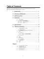
1
INSTRUCTION MANUAL
NL120 Ethernet Module
Revision: 4/15
C o p y r i g h t © 2 0 0 6 - 2 0 1 5
C a m p b e l l S c i e n t i f i c , I n c .
Limited Warranty
“Products manufactured by CSI are warranted by CSI to be free from defects in
materials and workmanship under normal use and service for twelve months
from the date of shipment unless otherwise specified in the corresponding
product manual. (Product manuals are available for review online at
www.campbellsci.com.) Products not manufactured by CSI, but that are resold
by CSI, are warranted only to the limits extended by the original manufacturer.
Batteries, fine-wire thermocouples, desiccant, and other consumables have no
warranty. CSI’s obligation under this warranty is limited to repairing or
replacing (at CSI’s option) defective Products, which shall be the sole and
exclusive remedy under this warranty. The Customer assumes all costs of
removing, reinstalling, and shipping defective Products to CSI. CSI will return
such Products by surface carrier prepaid within the continental United States of
America. To all other locations, CSI will return such Products best way CIP
(port of entry) per Incoterms ® 2010. This warranty shall not apply to any
Products which have been subjected to modification, misuse, neglect, improper
service, accidents of nature, or shipping damage. This warranty is in lieu of all
other warranties, expressed or implied. The warranty for installation services
performed by CSI such as programming to customer specifications, electrical
connections to Products manufactured by CSI, and Product specific training, is
part of CSI's product warranty. CSI EXPRESSLY DISCLAIMS AND
EXCLUDES ANY IMPLIED WARRANTIES OF MERCHANTABILITY
OR FITNESS FOR A PARTICULAR PURPOSE. CSI hereby disclaims,
to the fullest extent allowed by applicable law, any and all warranties and
conditions with respect to the Products, whether express, implied or
statutory, other than those expressly provided herein.”
Assistance
Products may not be returned without prior authorization. The following
contact information is for US and international customers residing in countries
served by Campbell Scientific, Inc. directly. Affiliate companies handle
repairs for customers within their territories. Please visit
www.campbellsci.com to determine which Campbell Scientific company serves
your country.
To obtain a Returned Materials Authorization (RMA), contact CAMPBELL
SCIENTIFIC, INC., phone (435) 227-9000. After an application engineer
determines the nature of the problem, an RMA number will be issued. Please
write this number clearly on the outside of the shipping container. Campbell
Scientific’s shipping address is:
CAMPBELL SCIENTIFIC, INC.
RMA#_____
815 West 1800 North
Logan, Utah 84321-1784
For all returns, the customer must fill out a “Statement of Product Cleanliness
and Decontamination” form and comply with the requirements specified in it.
The form is available from our web site at www.campbellsci.com/repair. A
completed form must be either emailed to [email protected] or faxed to
(435) 227-9106. Campbell Scientific is unable to process any returns until we
receive this form. If the form is not received within three days of product
receipt or is incomplete, the product will be returned to the customer at the
customer’s expense. Campbell Scientific reserves the right to refuse service on
products that were exposed to contaminants that may cause health or safety
concerns for our employees.
Precautions
DANGER — MANY HAZARDS ARE ASSOCIATED WITH INSTALLING, USING, MAINTAINING, AND WORKING ON OR AROUND
TRIPODS, TOWERS, AND ANY ATTACHMENTS TO TRIPODS AND TOWERS SUCH AS SENSORS, CROSSARMS, ENCLOSURES,
ANTENNAS, ETC. FAILURE TO PROPERLY AND COMPLETELY ASSEMBLE, INSTALL, OPERATE, USE, AND MAINTAIN TRIPODS,
TOWERS, AND ATTACHMENTS, AND FAILURE TO HEED WARNINGS, INCREASES THE RISK OF DEATH, ACCIDENT, SERIOUS
INJURY, PROPERTY DAMAGE, AND PRODUCT FAILURE. TAKE ALL REASONABLE PRECAUTIONS TO AVOID THESE HAZARDS.
CHECK WITH YOUR ORGANIZATION'S SAFETY COORDINATOR (OR POLICY) FOR PROCEDURES AND REQUIRED PROTECTIVE
EQUIPMENT PRIOR TO PERFORMING ANY WORK.
Use tripods, towers, and attachments to tripods and towers only for purposes for which they are designed. Do not exceed design
limits. Be familiar and comply with all instructions provided in product manuals. Manuals are available at www.campbellsci.com or
by telephoning (435) 227-9000 (USA). You are responsible for conformance with governing codes and regulations, including safety
regulations, and the integrity and location of structures or land to which towers, tripods, and any attachments are attached. Installation
sites should be evaluated and approved by a qualified engineer. If questions or concerns arise regarding installation, use, or
maintenance of tripods, towers, attachments, or electrical connections, consult with a licensed and qualified engineer or electrician.
General
• Prior to performing site or installation work, obtain required approvals and permits. Comply
with all governing structure-height regulations, such as those of the FAA in the USA.
• Use only qualified personnel for installation, use, and maintenance of tripods and towers, and
any attachments to tripods and towers. The use of licensed and qualified contractors is
highly recommended.
• Read all applicable instructions carefully and understand procedures thoroughly before
beginning work.
• Wear a hardhat and eye protection, and take other appropriate safety precautions while
working on or around tripods and towers.
• Do not climb tripods or towers at any time, and prohibit climbing by other persons. Take
reasonable precautions to secure tripod and tower sites from trespassers.
• Use only manufacturer recommended parts, materials, and tools.
Utility and Electrical
• You can be killed or sustain serious bodily injury if the tripod, tower, or attachments you are
installing, constructing, using, or maintaining, or a tool, stake, or anchor, come in contact
with overhead or underground utility lines.
• Maintain a distance of at least one-and-one-half times structure height, 20 feet, or the
distance required by applicable law, whichever is greater, between overhead utility lines and
the structure (tripod, tower, attachments, or tools).
• Prior to performing site or installation work, inform all utility companies and have all
underground utilities marked.
• Comply with all electrical codes. Electrical equipment and related grounding devices should
be installed by a licensed and qualified electrician.
Elevated Work and Weather
• Exercise extreme caution when performing elevated work.
• Use appropriate equipment and safety practices.
• During installation and maintenance, keep tower and tripod sites clear of un-trained or nonessential personnel. Take precautions to prevent elevated tools and objects from dropping.
• Do not perform any work in inclement weather, including wind, rain, snow, lightning, etc.
Maintenance
• Periodically (at least yearly) check for wear and damage, including corrosion, stress cracks,
frayed cables, loose cable clamps, cable tightness, etc. and take necessary corrective actions.
• Periodically (at least yearly) check electrical ground connections.
WHILE EVERY ATTEMPT IS MADE TO EMBODY THE HIGHEST DEGREE OF SAFETY IN ALL CAMPBELL SCIENTIFIC PRODUCTS,
THE CUSTOMER ASSUMES ALL RISK FROM ANY INJURY RESULTING FROM IMPROPER INSTALLATION, USE, OR
MAINTENANCE OF TRIPODS, TOWERS, OR ATTACHMENTS TO TRIPODS AND TOWERS SUCH AS SENSORS, CROSSARMS,
ENCLOSURES, ANTENNAS, ETC.
Table of Contents
PDF viewers: These page numbers refer to the printed version of this document. Use the
PDF reader bookmarks tab for links to specific sections.
1. Introduction ................................................................. 1
2. Cautionary Statements ............................................... 1
3. Initial Inspection ......................................................... 1
4. Quickstart .................................................................... 2
4.1
4.2
Physical Setup ...................................................................................... 2
Communicating via Ethernet ................................................................ 2
4.2.1 Step 1 – Configure Datalogger ...................................................... 2
4.2.2 Step 2 – LoggerNet Setup ............................................................. 3
4.2.3 Step 3 – Connect ........................................................................... 4
5. Specifications ............................................................. 4
6. TCP/IP Functionality ................................................... 5
6.1
6.2
6.3
6.4
6.5
6.6
6.7
6.8
6.9
Communicating over TCP/IP ............................................................... 6
6.1.1 Data Callback ................................................................................ 6
6.1.2 Datalogger-to-Datalogger Communication ................................... 7
HTTP Web Server ................................................................................ 7
FTP ....................................................................................................... 8
6.3.1 FTP Server .................................................................................... 8
6.3.1.1 Step 1 – Configure Datalogger ......................................... 10
6.3.1.2 Step 2 – Access File System............................................. 10
6.3.2 FTP Client ................................................................................... 10
Telnet ................................................................................................. 11
Ping .................................................................................................... 11
Serial Server ....................................................................................... 11
6.6.1 Serial Input .................................................................................. 11
6.6.2 Serial Output ............................................................................... 12
TCP ModBus...................................................................................... 12
DHCP ................................................................................................. 12
DNS.................................................................................................... 12
Figures
4-1.
4-2.
5-1.
6-1.
6-2.
6-3.
NL120 attached to a CR1000 ............................................................... 2
LoggerNet setup ................................................................................... 4
NL120 Ethernet Module....................................................................... 5
Datalogger home page.......................................................................... 8
FTP root directory ................................................................................ 9
FTP USR directory............................................................................... 9
i
NL120 Ethernet Module
1.
Introduction
Campbell Scientific’s NL120 Ethernet Module enables 10Base-T Ethernet
communications. It allows the datalogger to communicate over a local network
or a dedicated Internet connection via TCP/IP. This small, rugged
communication device connects to the 40-pin peripheral port on a CR1000 or
CR3000 datalogger.
This manual describes how to use LoggerNet to connect to your datalogger
with an NL120 attached. You can also use other software packages such as
PC400, RTDAQ, or LoggerLink Mobile Apps for iOS and Android.
Before using the NL120, please study:
•
•
•
Section 2, Cautionary Statements (p. 1)
Section 3, Initial Inspection (p. 1)
Section 4, Quickstart (p. 2)
The Quickstart section explains how to quickly begin using an NL120 for
straightforward Ethernet communications. Section 6 describes in detail the
TCP/IP functionality of the NL120.
2.
3.
Cautionary Statements
•
The NL120 is rugged, but it should be handled as a precision scientific
instrument.
•
The 28033 Surge Suppressor and/or a shielded, 10Base-T Ethernet cable
should be used for locations susceptible to power surges and for cable
length longer than 9 ft.
•
Always power down the datalogger before installing or removing the
NL120 to or from the datalogger.
•
The first time an NL120 is attached to a datalogger, the datalogger’s
memory has to be reorganized to allow room in memory for the IP stack.
To avoid the loss of data, collect your data before attaching the NL120 to a
datalogger.
Initial Inspection
Upon receipt of the NL120, inspect the packaging and contents for damage.
File damage claims with the shipping company.
1
NL120 Ethernet Module
4.
Quickstart
This section describes the basics of communicating via Ethernet with the
NL120.
4.1
Physical Setup
CAUTION
Always power down the datalogger before installing or
removing the NL120 to or from the datalogger.
After powering down the datalogger, plug the NL120 into the datalogger
peripheral port (see FIGURE 4-1). Attach Ethernet cable to the 10Base-T port.
If using the 28033 Surge Protector, connect the other end of the Ethernet cable
to the 28033 and connect another Ethernet cable to the other end of the 28033.
Restore power to the datalogger.
FIGURE 4-1. NL120 attached to a CR1000
4.2
Communicating via Ethernet
4.2.1 Step 1 – Configure Datalogger
2
a.
Connect serial cable from PC COM port to datalogger RS-232 port.
b.
Open Campbell Scientific’s Device Configuration Utility. Select the
device type of the datalogger (CR1000 or CR3000), the appropriate Serial
Port, and baud rate. Connect to the datalogger.
c.
Under the TCP/IP tab, input the IP Address, Subnet Mask, and IP
gateway. These values should be provided by your network
administrator.
NL120 Ethernet Module
d.
Press the Apply button to save the changes and then close the Device
Configuration Utility.
NOTE
A temporary IP address may be obtained from a DHCP server.
For more information, see Section 6.8, DHCP (p. 12).
NOTE
The NL120 must be connected to the datalogger before
configuring the datalogger with the Device Configuration Utility.
If it is not connected, the TCP/IP settings will not be displayed.
4.2.2 Step 2 – LoggerNet Setup
The next step is to run LoggerNet and configure it to connect to the datalogger
via the Ethernet port.
a.
In LoggerNet’s Setup Screen, press Add Root and choose IPPort. Input
the datalogger’s IP address and port number. The IP address and port
number are input on the same line and separated by a colon. (The
datalogger’s default port number is 6785. It can be changed using Device
Configuration Utility or by modifying its value in the Status Table.)
b.
Add a PakBus port and set the desired baud rate.
c.
Add the datalogger (CR1000 or CR3000). Input the PakBus address of
the datalogger.
3
NL120 Ethernet Module
FIGURE 4-2. LoggerNet setup
4.2.3 Step 3 – Connect
You are now ready to connect to your datalogger using the LoggerNet Connect
screen.
Datalogger program transfer, table-data display, and data collection are now
possible.
5.
Specifications
Datalogger Compatibility:
CR1000, CR3000
Power Requirements:
12 V supplied through datalogger’s peripheral
port
Typical Current Drain:
20 mA
(Note: To save power, the IPNetPower()
instruction can be used to turn off power to the
NL120. See the CRBasic help for an example
of using the IPNetPower instruction.)
Operating Temp. Range:
–25 to 50 °C Standard
–40 to 85 °C Extended
EMI and ESD Protection:
Meets requirements for a class-A device under
European Standards
Application of Council Directive(s):
89/336/EEC as amended by 89/336/EEC and
93/68/EEC
Standards to which conformity is declared:
EN55022-1: 1995 and EN50082-1: 1992
4
NL120 Ethernet Module
Cable Requirements:
NOTE
Use a straight-through Ethernet cable when the
cable is run from the hub to the NL120. Use a
crossover Ethernet cable when the cable is run
directly from the computer to the NL120. Use
a shielded Ethernet cable and/or the 28033
surge suppressor when the cable length is
greater than 9 ft.
The maximum recommended segment length for 10BaseT
networks using CAT5 cable is 100 meters. Segment length is the
length of cable between the NL device and the Ethernet repeater,
hub, switch, or router it is connected to.
Ethernet Speed:
10Base-T (10 Mbps), half-duplex
Software Requirements:
LoggerNet 3.2 or later
PC400 1.3 or later
Dimensions:
10.2 x 6.4 x 2.8 cm (4.0 x 2.5 x 1.1 in)
Weight:
66.6 g (2.35 oz)
FIGURE 5-1. NL120 Ethernet Module
6.
TCP/IP Functionality
This section describes the main TCP/IP functionality of a datalogger with an
NL120 attached. Additional functionality may be added in the future. For
5
NL120 Ethernet Module
more information, refer to the Information Services section of the datalogger
manual and CRBasic Editor Help.
6.1
Communicating over TCP/IP
Once the datalogger, the NL120, and LoggerNet have been set up as described
in Sections 4.1, Physical Setup (p. 2), and 4.2, Communicating via Ethernet (p. 2),
communication is possible over TCP/IP. This includes program send and data
collection. These are straightforward operations and are accomplished through
LoggerNet’s Connect screen. For more information, see the LoggerNet
manual.
Data callback and datalogger-to-datalogger communications are also possible
over TCP/IP, as well as the creation of simple HTML pages to view datalogger
variables using a web browser.
6.1.1 Data Callback
The following program is an example of doing data callback over TCP/IP. It
first checks to see if a port to the LoggerNet Server already exists. (The
LoggerNet Server is assumed to be at the default PakBus Address, 4094.) If
not, a socket to LoggerNet is opened using the TCPOpen() instruction. The
SendVariables() instruction is then used to send data.
PROGRAM
'CR1000
'IP_Callback.cr1
'LoggerNet server Pak Bus Address assumed = 4094
'PC IP address assumed = 192.168.7.231
'LoggerNet IPPort "IP Port Used for Call-Back" = 6785
'LoggerNet IPPort "Call-Back Enabled" is checked
'LoggerNet CR1000 "Call-Back Enabled" is checked
'LoggerNet PakBusPort "PakBus Port Always Open" is checked
'IP Call-back using auto-discover (-1) neighbor in SetVariables
Public PanelTemperature, BatteryVoltage, Result1, dummy1
Dim Socket as LONG
DataTable (CLBK1,1,1000)
DataInterval (0,0,Sec,10)
Sample (1,PanelTemperature,FP2)
Sample (1,BatteryVoltage,FP2)
EndTable
BeginProg
Scan (5,Sec,6,0)
PanelTemp (PanelTemperature,250)
Battery (BatteryVoltage)
If not Route(4094) then Socket = TCPOpen ("192.168.7.231",6785,0)
SendVariables (Result1,Socket,-1,4094,0000,100,"Public","Callback",dummy1,1)
CallTable CLBK1
NextScan
EndProg
6
NL120 Ethernet Module
6.1.2 Datalogger-to-Datalogger Communication
Communication between dataloggers is possible over TCP/IP. In order to do
this, a socket must be opened between the two dataloggers. This is done using
the TCPOpen() instruction. The socket opened by this instruction is then used
by the instructions performing datalogger-to-datalogger communication.
The example program below gets the battery voltage from a remote datalogger
and sends its panel temperature to the remote datalogger. The remote
datalogger is at IP address 192.168.7.125 and port 6785 is used for
communication between the dataloggers. The remote datalogger must have its
battery voltage stored in a public variable, BattVolt. It must also have a Public
variable declared, PTemp_Base. This will be used to store the panel
temperature of the base datalogger.
PROGRAM
'CR1000
'DL-to-Dl_Comms_1.cr1
'Send this program to CR1000 #1
'Remote CR1000 #2 has PBA = 2, IP addr = 192.168.7.125, and port 6785
Public BattVolt,, BattVolt_Remote
Public PTemp
Public Result1, Result2
Dim Socket as LONG
DataTable (Test,1,-1)
DataInterval (0,12,Sec,10)
Minimum (1,BattVolt,FP2,0,False)
EndTable
BeginProg
Scan(2,Sec,0,0)
Socket = TCPOpen(“192.168.7.125”,6785,0)
BatteryVoltage(BattVolt)
PanelTemp(PTemp,250)
GetVariables (Result1,Socket,-1,2,0000,50,"Public","BattVolt",BattVolt_Remote,1)
SendVariables (Result2,Socket,-1,2,0000,50,"Public","PTemp",PTemp_Base,1)
CallTable(Test)
NextScan
EndProg
6.2
HTTP Web Server
Typing the datalogger’s IP address into a web browser will bring up its home
page as shown in FIGURE 6-1. This default home page provides links to the
current record in all tables, including data tables, the Status table and the Public
table. Clicking on a Newest Record link will bring up the latest record for that
table. It will be automatically refreshed every 10 seconds. Links are also
provided to the last 24 records in each data table. Clicking on a Last 24
Records link will bring up the last 24 records for that table. The Last 24
7
NL120 Ethernet Module
Records Display must be manually refreshed. In addition, links are provided to
all HTML files, all XML files, and all JPEG files in the datalogger.
FIGURE 6-1. Datalogger home page
If there is a default.html file on the datalogger, this will automatically become
the user-configurable home page.
The WebPageBegin/WebPageEnd declarations and the HTTPOut instruction
can be used in a datalogger program to create HTML or XML files that can be
viewed by the browser. For more information on using these instructions, see
the datalogger manual or CRBasic Editor Help.
NOTE
6.3
FileOpen() and FileWrite() can be used to create HTML pages,
but this requires first writing the file to the datalogger’s USR
drive. It is less convenient, and the page will be only as current as
it is written to the file.
FTP
6.3.1 FTP Server
With an NL120 attached, the datalogger will automatically run an FTP server.
This allows Windows Explorer to access the datalogger’s file system via FTP.
In the FTP world, the “drives” on the datalogger are mapped into directories
(or folders). The “root directory” on the datalogger will include CPU and
possibly USR. The files will be contained in one of these directories. Files can
be pasted and copied to/from the datalogger “drives” as if they were drives on
the PC. Files on the datalogger drives can also be deleted through FTP.
8
NL120 Ethernet Module
FIGURE 6-2. FTP root directory
FIGURE 6-3. FTP USR directory
9
NL120 Ethernet Module
In order to use FTP, the datalogger’s FTP User Name and FTP Password must
be set. This is done using Device Configuration Utility.
6.3.1.1 Step 1 – Configure Datalogger
NOTE
a.
Connect serial cable from PC COM port to datalogger RS-232 port.
b.
Open Campbell Scientific’s Device Configuration Utility. Select the
device type of the datalogger (CR1000 or CR3000), the appropriate Serial
Port, and baud rate. Connect to the datalogger.
c.
Under the Net Services tab, verify that FTP Enabled is checked. Input the
FTP User Name and FTP Password.
d.
Press the Apply button to save the changes and then close the Device
Configuration Utility.
Using “anonymous” as the user name with no password allows
FTP access without inputting a user name or password.
6.3.1.2 Step 2 – Access File System
NOTE
a.
Datalogger must be set up for Ethernet communications as explained in
Sections 4.1, Physical Setup (p. 2), and 4.2, Communicating via Ethernet (p. 2)
(Step 1 only).
b.
Open a Windows Explorer window. Enter
ftp://username:[email protected] where nnn.nnn.nnn.nnn is the
IP address of the datalogger.
If the user name is “anonymous” with no password, enter
ftp://nnn.nnn.nnn.nnn where nnn.nnn.nnn.nnn is the IP address of
the datalogger.
6.3.2 FTP Client
The datalogger can also act as an FTP Client to send a file to or get a file from
an FTP Server (for example, another datalogger or web camera). This is done
using the FTPClient() instruction. The following program is an example of
using FTPClient() to send a file to another datalogger and get a file from that
datalogger. The first parameter in the instruction is the FTP Server’s IP
address. The second parameter is the FTP username. The third parameter is
the FTP password. The fourth parameter is the local filename. The fifth
parameter is the remote file name. The final parameter is the put/get option: 0
for put and 1 for get. The instruction returns –1 if the instruction was
successful and 0 if it was not.
10
NL120 Ethernet Module
PROGRAM
'CR1000
'FTPClient.cr1
Public Result1, Result2
BeginProg
Scan (20,Sec,1,1)
Result1 = FTPClient("192.168.7.85","user","password","USR:pic.jpg","USR:pic.jpg",0)
Result2 = FTPClient("192.168.7.85","user","password","USR:file.html”,"USR:file.html",1)
NextScan
EndProg
6.4
Telnet
Telnetting to the datalogger’s IP address allows access to the same commands
as the Terminal Emulator in LoggerNet Connect screen’s Datalogger menu.
6.5
Ping
Pinging the datalogger’s IP address may be used to verify communication.
6.6
Serial Server
With an NL120 attached, the datalogger can be configured to act as a serial
server over the 10Base-T port. (A serial server is a device that allows serial
communication over a TCP/IP port.) This function may be useful when
communicating with a serial sensor over an Ethernet.
6.6.1 Serial Input
The TCPOpen() instruction must be used first to open up a TCP socket. An
example of this instruction is shown below. The first parameter in TCPOpen()
is the IP address to open a socket to. “” means to listen on this port rather than
connect. The second parameter is the port number to be used. The third
parameter is buffer size. For a SerialIn() instruction that will use this
connection, it gives a buffer size. The TCPOpen() instruction returns the
socket number of the open connection or ‘0’ if it cannot open a connection.
socket = TCPOpen(“”,6784,100)
Once a socket has been opened with the TCPOpen() instruction, serial data
may be received with a SerialIn() Instruction. An example of this instruction
is shown below. The first parameter is the string variable into which the
incoming serial data will be stored. The second parameter is the socket
returned by the TCPOpen() instruction. The third parameter is the timeout.
The fourth parameter is the termination character. The last parameter is the
maximum number of characters to expect per input. For more information on
this instruction, see the CRBasic Editor Help.
SerialIn(Received,socket,0,13,100)
11
NL120 Ethernet Module
6.6.2 Serial Output
The TCPOpen() instruction must be used first to open up a TCP socket. An
example of this instruction is shown below. The first parameter in TCPOpen()
is the IP address to open a socket to. The second parameter is the port number
to be used. The third parameter is buffer size. The TCPOpen() instruction
returns the socket number of the open connection or ‘0’ if it cannot open a
connection.
socket = TCPOpen(“192.168.7.85”,6784,100)
Once a socket has been opened with the TCPOpen() instruction, serial data
may be sent out with a SerialOut() instruction. An example of this instruction
is shown below. The first parameter is the socket returned by the TCPOpen()
instruction. The second parameter is the variable to be sent out. The third
parameter is the wait string. The last parameter is the total number of times the
datalogger should attempt to send the variable. For more information on this
instruction, see the CRBasic Editor Help.
result = SerialOut(socket,sent,"",0,100)
6.7
TCP ModBus
With an NL120 attached, the datalogger can be set up as a TCP ModBus
Master or Slave device. For information on configuring the datalogger as a
TCP ModBus Master or Slave, see the ModBus section of the datalogger
manual.
6.8
DHCP
The IP address of the datalogger may be obtained through DHCP, if a DHCP
server is available. The DHCP address will be automatically assigned if there
is a DHCP server available and no static IP address has been entered. The IP
address should be available a few minutes after the datalogger has been
powered up with the NL120 attached and Ethernet cable plugged in. The IP
address can be found with Device Configuration Utility’s Settings tab under
TCP/IP info. It can also be found using a CR1000KD attached to the
datalogger. Go to Configure, Settings | Settings, scroll down to IP Status and
press the right arrow.
An IP address obtained through DHCP is not static but is leased for a period of
time set by the network administrator. The address may change, if the
datalogger is powered down.
6.9
DNS
The datalogger provides a DNS client that can query a DNS server to resolve a
fully qualified domain name. When a DNS server is available, domain names
can be used in place of the IP address in the datalogger instructions.
12
Campbell Scientific Companies
Campbell Scientific, Inc. (CSI)
815 West 1800 North
Logan, Utah 84321
UNITED STATES
www.campbellsci.com • [email protected]
Campbell Scientific Centro Caribe S.A. (CSCC)
300 N Cementerio, Edificio Breller
Santo Domingo, Heredia 40305
COSTA RICA
www.campbellsci.cc • [email protected]
Campbell Scientific Africa Pty. Ltd. (CSAf)
PO Box 2450
Somerset West 7129
SOUTH AFRICA
www.csafrica.co.za • [email protected]
Campbell Scientific Ltd. (CSL)
Campbell Park
80 Hathern Road
Shepshed, Loughborough LE12 9GX
UNITED KINGDOM
www.campbellsci.co.uk • [email protected]
Campbell Scientific Australia Pty. Ltd. (CSA)
PO Box 8108
Garbutt Post Shop QLD 4814
AUSTRALIA
www.campbellsci.com.au • [email protected]
Campbell Scientific Ltd. (CSL France)
3 Avenue de la Division Leclerc
92160 ANTONY
FRANCE
www.campbellsci.fr • [email protected]
Campbell Scientific (Beijing) Co., Ltd.
8B16, Floor 8 Tower B, Hanwei Plaza
7 Guanghua Road
Chaoyang, Beijing 100004
P.R. CHINA
www.campbellsci.com • [email protected]
Campbell Scientific Ltd. (CSL Germany)
Fahrenheitstraße 13
28359 Bremen
GERMANY
www.campbellsci.de • [email protected]
Campbell Scientific do Brasil Ltda. (CSB)
Rua Apinagés, nbr. 2018 ─ Perdizes
CEP: 01258-00 ─ São Paulo ─ SP
BRASIL
www.campbellsci.com.br • [email protected]
Campbell Scientific Spain, S. L. (CSL Spain)
Avda. Pompeu Fabra 7-9, local 1
08024 Barcelona
SPAIN
www.campbellsci.es • [email protected]
Campbell Scientific Canada Corp. (CSC)
14532 – 131 Avenue NW
Edmonton AB T5L 4X4
CANADA
www.campbellsci.ca • [email protected]
Please visit www.campbellsci.com to obtain contact information for your local US or international representative.