1
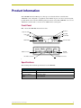
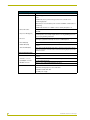
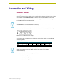
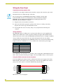
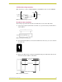
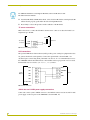
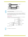
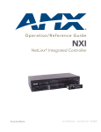
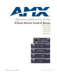
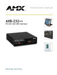
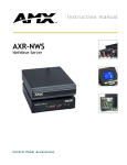
instruction manual
AXB-TM5
Television Manager
AXlink Bus Controllers
AMX Limited Warranty and Disclaimer
AMX Corporation warrants its products to be free of defects in material and workmanship under normal use for
three (3) years from the date of purchase from AMX Corporation, with the following exceptions:
•
Electroluminescent and LCD Control Panels are warranted for three (3) years, except for the display and touch
overlay components that are warranted for a period of one (1) year.
•
Disk drive mechanisms, pan/tilt heads, power supplies, MX Series products, and KC Series products are
warranted for a period of one (1) year.
•
Unless otherwise specified, OEM and custom products are warranted for a period of one (1) year.
•
Software is warranted for a period of ninety (90) days.
•
Batteries and incandescent lamps are not covered under the warranty.
This warranty extends only to products purchased directly from AMX Corporation or an Authorized AMX Dealer.
AMX Corporation is not liable for any damages caused by its products or for the failure of its products to perform.
This includes any lost profits, lost savings, incidental damages, or consequential damages. AMX Corporation is not
liable for any claim made by a third party or by an AMX Dealer for a third party.
This limitation of liability applies whether damages are sought, or a claim is made, under this warranty or as a tort
claim (including negligence and strict product liability), a contract claim, or any other claim. This limitation of
liability cannot be waived or amended by any person. This limitation of liability will be effective even if AMX
Corporation or an authorized representative of AMX Corporation has been advised of the possibility of any such
damages. This limitation of liability, however, will not apply to claims for personal injury.
Some states do not allow a limitation of how long an implied warranty last. Some states do not allow the limitation or
exclusion of incidental or consequential damages for consumer products. In such states, the limitation or exclusion of
the Limited Warranty may not apply. This Limited Warranty gives the owner specific legal rights. The owner may
also have other rights that vary from state to state. The owner is advised to consult applicable state laws for full
determination of rights.
EXCEPT AS EXPRESSLY SET FORTH IN THIS WARRANTY, AMX CORPORATION MAKES NO
OTHER WARRANTIES, EXPRESSED OR IMPLIED, INCLUDING ANY IMPLIED WARRANTIES OF
MERCHANTABILITY OR FITNESS FOR A PARTICULAR PURPOSE. AMX CORPORATION
EXPRESSLY DISCLAIMS ALL WARRANTIES NOT STATED IN THIS LIMITED WARRANTY. ANY
IMPLIED WARRANTIES THAT MAY BE IMPOSED BY LAW ARE LIMITED TO THE TERMS OF THIS
LIMITED WARRANTY.
Table of Contents
Table of Contents
Product Information .................................................................................................1
Front Panel........................................................................................................................ 1
Specifications .................................................................................................................... 1
Connection and Wiring ............................................................................................3
Device DIP Switch............................................................................................................. 3
Wiring the Rear Panel ....................................................................................................... 4
Preparing/connecting captive wires ......................................................................................... 4
Wiring Guidelines ..................................................................................................................... 4
Using the AXlink connector for data and power ....................................................................... 4
CC-IRC emitter wiring connections .......................................................................................... 5
IR emitter to device installation ................................................................................................ 5
TV sensor connections............................................................................................................. 6
PCS connections...................................................................................................................... 6
AXlink data and 12 VDC power supply connections ................................................................ 6
IRX-SM connections ................................................................................................................ 7
Programming ............................................................................................................9
Channel Setting Commands ............................................................................................. 9
Device Assignment .................................................................................................................. 9
System Send_Commands............................................................................................... 10
AXB-TM5 Television Manager
i
Table of Contents
ii
AXB-TM5 Television Manager
Product Information
Product Information
The AXB-TM5 Television Manager is a microprocessor-based television controller. The
AXB-TM5 can be configured as a peripheral on the AXlink. As part of an Axcess Control System,
provides media source selection and management via remote control. The AXB-TM5 acts as a local
AXlink bus controller and as a receiver for an AMX wireless control panel.
Front Panel
FIG. 1 shows the AXB-TM5 front and rear views.
IR Sensor
Response LED
IR In LED
Device DIP
switch
IR Out LED
DEVICE
TV
POWER
IR
AXlink
RESPONSE
OUT
IN
ON
GND
IN
12V
AUX
GND
I/O 1
I/O 3
I/O 2
12V
TV Power LED
TO
IRX-SG
INPUT / OUTPUT
I/O 4
GND
GND
TV
IRE
IR
AXP
WIRED
PWR
AXM
GND
AXlink
SER
AXlink LED
IRX-SM
connector
AXlink connector
IR emitter connector
Input/Output connector
FIG. 1 AXB-TM5 front and rear views
Specifications
The following table details the specifications for the AXB-TM5.
Specifications
Dimensions (HWD)
1.50" x 5.09" x 5.27" (3.81 cm x 12.93 cm x 13.39 cm)
Enclosure
High impact black matte plastic
Power Consumption
200 mA @ 12 VDC
Weight
11.0 oz. (312.0 g)
AXB-TM5 Television Manager
1
Product Information
Specifications (Cont.)
Front Panel Components
AXlink LED
AXlink LED (green and blinks to indicate AXlink communication activity and
power:
• Full-Off indicates no power is being received or the controller is not
• functioning properly.
• One blink per second indicates power is active and AXlink communication is
• functioning.
• Full-On indicates there is no AXlink control or activity, but power is on.
Device DIP switch
An eight-position DIP switch used to set the AXlink device number for the
AXB-TM5.
Response LED (big red)
It can be programmed for flash, full On, and Off modes for control
system responses to local input signals. Refer to the Programming section on
page 9 for programming information.
IR sensor
It receives incoming IR signals from a wireless transmitter. Internal high- and
low-frequency (455 kHz or 38 kHz) IR sensors for AMX IR panels.
IR In LED (Red)
Flashes when the AXB-TM5 receives an IR signal from a wireless transmitter.
IR Out LED (Red)
Flashes when the AXB-TM5 IR port sends an IR command to the television
receiver.
TV Power LED (Red)
Lights when the CC-XPS External Frequency Television Scan Sensor detects
power on a television or monitor as the horizontal scanning frequency from the
television receiver.
Rear Panel Components
AXlink connector
Receives power and information via the AXlink bus and AXlink system
controller.
IR Emitter connector
TV sensor connector to detect horizontal scan frequencies from 15 - 65kHz.
Input/Output connector
Four TTL input/output ports.
IRX-SM connector
Allows for up to eight (parallel) IRX-SM connections.
Optional Accessories
• AXB-TM5 control box unit
• CC-XPS scanning frequency sensor with cable
• CC-IRC IR emitter with cable
• 12 VDC power supply
2
AXB-TM5 Television Manager
Connection and Wiring
Connection and Wiring
Device DIP Switch
The eight-position Device DIP switch, shown in FIG. 2, sets the AXlink device number. Every
device on the bus must have a unique device code. An eight-position DIP switch is used to set the
device number for the AXB-TM5. The device number must match the number assigned in the
Axcess software program. The AXlink device number range is 1-255 and is sent according to the
Device DIP switch positions and their values.
After setting the AXlink device number, remove and reconnect the AXlink connector
on the AXB-TM5 to store the new number into memory.
As an example, FIG. 2 is set to 85 (1 + 4 + 16 + 64 = 85), which is the factory default setting.
FIG. 2 Device Code DIP switch setting example
The following table describes the Device Code DIP switch settings and its corresponding DIP
switch arrangements.
Device DIP switch settings
Position
1
2
3
4
5
6
7
8
Value
1
2
4
8
16
32
64
128
The device number takes effect only on power-up. If you later change the device
number, remove and reconnect the AXlink connector. This enters the new device
number into memory.
AMX standard device numbers are assigned as follows:
!
Cards are 1 through 25.
!
Boxes are 96 through 127.
!
Panels are 128 through 255.
AXB-TM5 Television Manager
3
Connection and Wiring
Wiring the Rear Panel
Preparing/connecting captive wires
You will need a wire stripper and flat-blade screwdriver to prepare and connect the captive wires.
Never pre-tin wires for compression-type connections.
Do not connect power to the AXB-TM5 until the wiring is complete. If you are using
power from AXlink, disconnect the wiring from the control system before wiring the
AXB-TM5. If you are using an optional 12 VDC power supply, apply power to the
AXB-TM5 only after installation is complete.
1. Strip 0.25 inch of wire insulation off all wires.
2. Insert each wire into the appropriate opening on the connector according to the wiring
diagrams and connector types described in this section.
3. Do not tighten the screws excessively; doing so may strip the threads and damage the
connector.
Wiring Guidelines
The AXB-TM5 requires 12 VDC power to operate properly. The power can be supplied by the
AMX system's AXlink cable or with an optional 12 VDC power supply. The maximum wiring
distance between the control system and AXB-TM5 is determined by power consumption, supplied
voltage, and the wire gauge used for the cable. The following table lists wire sizes and the
maximum lengths allowable between the AXB-TM5 and the control system. The maximum wiring
lengths are based on a minimum of 13.5 volts available at the control system's power supply.
Wiring Guidelines @ 200 mA
Wire size
Maximum wiring length
18 AWG
586.55 feet (178.78 meters)
20 AWG
371.29 feet (113.17 meters)
22 AWG
231.48 feet (70.56 meters)
24 AWG
145.91 feet (44.47 meters)
If the AXB-TM5 is installed farther away from the control system than recommended in the above
table, connect an external 12 VDC power supply to the two-pin PWR connector on the rear panel.
Using the AXlink connector for data and power
To use the AXlink 4-pin connector for data communication and for power supply, the incoming
PWR and GND cable from the control system must be connected to the AXlink cable connector
going to the control system as sown in the AXlink wiring diagram (FIG. 3).
PWR +
PWR +
AXP/TX
AXP/TX
AXM/RX
GND To the AXB-TM5
AXM/RX
GND To the Control system
FIG. 3 AXlink connector wiring diagram
4
AXB-TM5 Television Manager
Connection and Wiring
CC-IRC emitter wiring connections
FIG. 4 shows how to connect a CC-IRC IR Emitter to the IR Emitter connector on the AXB-TM5.
CC-IRC
Television
To emitter GND
connector
SIG
FIG. 4 CC-IRC Emitter wiring connections
IR emitter to device installation
The following steps describe the installation of the IR emitter to the television IR window.
1. Using a sharp edged tool (knife blade, razor knife, etc.), separate the factory-installed shell as
shown in FIG. 5.
FIG. 5 Removing factory-installed shell
2. Test-fit the IR shield (FIG. 6) to the television's IR window. If necessary, use scissors and trim
the shield to fit.
FIG. 6 IR shield
3. Remove the adhesive back covering from the IR shield and place the IR emitter diode into the
mirrored recessed area (FIG. 7) of the shield.
IR input window
IR shield
IR emitter code
CC-IRC cable assembly
FIG. 7 IR emitter diode installed
AXB-TM5 Television Manager
5
Connection and Wiring
For additional information concerning the IR emitter, refer to the IR Sensors and
Receivers instruction manual.
4. Attach the IR shield, with IR emitter diode, to the television IR window, ensuring that the IR
emitter diode is properly positioned in the television input IR window.
5. Press firmly to activate the pressure-sensitive adhesive of the IR shield.
TV sensor connections
FIG. 8 shows how to connect the CC-XPS to the TV sensor connector to detect horizontal scan
frequencies up to 65 kHz.
CC-IRC
TV sensor
connector
GND
Television
SENSOR
FIG. 8 TV sensor wiring connections
PCS connections
The optional AMX Power Current Sensor (PCS) provides power sensing for equipment that does
not generate horizontal scan frequencies. Connect the optional PCS as shown in FIG. 9 for
automated power control using Send_Commands PON and POF. A PIN command must be sent to
the AXB-TM5 either from terminal mode or from within an Axcess program. If PIN is not used,
then the PCS state is received as [TM-Device, 251] for I/O 1.
Input/
Output
GND
GND
I/O 1
STANDBY
I/O 2
ON
I/O 3
PWR
PCS
I/O 4
12 VDC PWR
FIG. 9 PCS connections
AXlink data and 12 VDC power supply connections
Connect the control system's AXlink connector to the AXlink connector and an external 12 VDC
power supply on the rear panel of the AXB-TM5 as shown in FIG. 10.
6
AXB-TM5 Television Manager
Connection and Wiring
PWR
GND
12 VDC power
supply
PWR
PWR
AXP
AXP
AXM
AXM
GND
GND
FIG. 10 AXlink 12 VDC power supply wiring example
If you are using power from AXlink, disconnect the wiring from the Axcess Control
System before wiring the AXB-TM5.
Use a 12 VDC power supply when the distance between the control system and AXB-TM5 exceeds
the limits described in the Wiring Guidelines section on page 4. Make sure to connect only the
GND wire on the AXlink connector when using a 12 VDC power supply. Do not connect the PWR
wire to the AXlink connector's PWR (+) terminal.
IRX-SM connections
Connect one or more (eight maximum in parallel) optional IRX-SM sensors to the AXB-TM5 as
shown in FIG. 11. You can also use TX-series wired control panels.
GND
OUT
IRX-SM #2
AUX OUT
+12 VDC
To IRX-SG
GND
GND
IN
OUT
AUX
AUX OUT
PWR
+12 VDC
IRX-SM #1
FIG. 11 IRX-SM connections
This configuration is for 40 kHz operation only.
AXB-TM5 Television Manager
7
Connection and Wiring
8
AXB-TM5 Television Manager
Programming
Programming
You can program the AXB-TM5 to perform a wide variety of operations using Axcess
Send_Commands. This section describes channel settings, IR functions, and system
Send_Commands. Refer to the AXCESS Programming Guide for additional programming
information.
Channel Setting Commands
The AXB-TM5 use the channel setting commands listed in the following table.
AXB-TM5 Channel Settings
Channel
Function
1
Generates IR/Serial functions 1, else Off
2 - 127
Channels the generate IR code for the corresponding functions
128 - 247
Push and release channels for received IR code
248
A push on this channel indicates a power failure error
249
Response LED blinks when channels 249 and 250 are On
250
Response LED lights when channel is On
251
I/O is On (switch to GND) when channel is On
252
I/O 2 is On (switch to GND) when channel is On
253
I/O 3 is On (switch to GND) when channel is On
254
I/O 4 is On (switch to GND) when channel is On
255
Channel is On if the TV Power Sensor detects a horizontal scan frequency
Turning a channel (IR/Serial function) on while another one is currently on will
automatically turn the current one off first. Contact closure inputs on I/O 1 through I/O
4 will also generate PUSHes and RELEASEs on channels 251 through 254,
respectively.
Device Assignment
The device assignment must be the same as the device number set on the Device DIP switches
(FIG. 2 on page 3).
AXB-TM5 Television Manager
9
Programming
System Send_Commands
System Send_Commands are stored in the Axcess Control System and direct the AXB-TM5 to
perform various operations.
System Send_Commands
Command
Description
'CARON'
Turns the IR carrier On (default).
Example:
SEND_COMMAND AXBTMX,'CARON'
'CAROFF'
Turns the IR carrier Off.
Example:
SEND_COMMAND AXBTMX,'CAROFF'
'CH',<TV Channel>
Generates IR digit pulses to select a television channel number.
Channels 1-99 pulse as two digits.
Syntax:
"'CH',<TV Channel>"
Variables:
TV Channel = 0 through 199
Channels 100 and greater, the one-hundredth digit pulses as 127. If
IR function 21 (enter) exists, it follows the IR digit pulses. ’CTON’ sets
the pulse length for each digit and ’CTOF’ sets the time between each
digit or any after-pulse.
Example:
SEND_COMMAND AXBTMX,"'CH',25"
Sets the television connected to channel 25 on the AXB-TM5.
'CTOF',<Time>
Sets the single IR pulses off time between channel digits and IR
functions.
Syntax:
"'CTOF',<Time>"
Variables:
Time = 0 through 255 in tenths of a second
Time is stored in permanent memory. System default is 5 (.5 second).
This is the time between digits, or pulses, that are associated with an
SP command.
Example:
SEND_COMMAND AXBTMX,"'CTOF',10"
Sets the off-time pulse time (delay) to 1 second for the AXB-TM5.
'?CTOF'
Sends the current off-time pulse string ’CTOF,<Time>’ to the Control
system. The <Time> value is returned in .10 second increments.
Example:
SEND_COMMAND AXBTMX,'?CTOF'
Sends the current off-time pulse string from the AXB-TM5 to the
Control system in the ’CTOF <Time>’ format.
10
AXB-TM5 Television Manager
Programming
System Send_Commands (Cont.)
Command
Description
'CTON',<Time>
Sends the current on-time pulse string CTON,<Time> to the control
system.
Syntax:
"'CTON',<Time>"
Variables:
Time = 0 through 255 in tenths of a second
Time is stored in permanent memory. System default is 5 (.5 second).
Example:
SEND_COMMAND AXBTMX,"'CTON',20"
Sets the pulse length to 2 seconds on the AXB-TM5.
'?CTON'
Sends the current off-time pulse string ’CTOF,<Time>’ to the Control
system. The <Time> value is returned in .10 second increments.
Example:
SEND_COMMAND AXBTMX,'?CTON'
Sends the current on-time pulse string from the AXB-TM5 to the
control system in the ’CTON <Time>’ format.
'DC',<IR in>,<IR out>
Sets a direct connection so the ’IR out’ (IR function) data transmits
while the ’IR in’ code is received.
Syntax:
"'DC',<IR in>,<IR out>"
Variables:
IR in = custom IR functions assigned to hand-held IR transmitting
device
IR out = IR functions
The PUSH and RELEASE for the ’IR in’ code is not sent to the
AXC-EM. The maximum number of direct connections is 16.
Example:
SEND_COMMAND AXBTMX,"'DC',145,24"
Connects IR-in 145 to IR-out 24 and increases the volume level on the
equipment connected to the AXB-TM5.
'DE',<Time>
Set the delay time in .10 second increments for the television power
sensor (CC-XPS or PCS) to stabilize before sensing for a status
change.
Syntax:
"'DE',<Time>"
Variables:
Time = 0 through 255
System default time is 10 (1 second).
Example:
SEND_COMMAND AXBTMX,"'DE',10"
Sets the delay time to 1 second for the CC-XPS or PCS connected to
the AXB-TM5.
AXB-TM5 Television Manager
11
Programming
System Send_Commands (Cont.)
Command
Description
'?DE'
Sends the current television power sensor (CC-XPS) delay time string
’DE,<Time>’ to the AXC-EM. Set the <Time> value in .10 second
increments.
Example:
SEND_COMMAND AXBTMX,'?DE'
The AXB-TM5 sends the current television power sensor delay time to
the control system in the ’DE <Time>’ format.
'DK'
Deletes all direct connections set with the ’DC’ command.
Example:
SEND_COMMAND AXBTMX,'DK'
'PIF'
Disables the ’PIN’ command.
Example:
SEND_COMMAND AXBTMX,'PIF'
'PIN'
Turns on function that will OR together I/O 1 and frequency sensor to
determine actual TV status. I/O 2 will follow ’PON’ and ’POF’
commands. The status of this function is stored in permanent memory
until changed.
Example:
SEND_COMMAND AXBTMX,'PIN'
'POD'
Disables the current ’PON’ (power On) or ’POF’ (power Off) command
settings. Channel 255 changes are enabled.
Example:
SEND_COMMAND AXBTMX,'POD'
'POF'
Sends IR function 28 (if available) to turn device power off. After three
attempts, if the CC-XPS (power sensor) still detects a power-on status, the television controller starts processing stored buffer commands. Then, if another IR function 28 fails to turn the television's
power off, the television controller sends a ’PUSH’ and ’RELEASE’ to
channel 248 and generates a power failure error. If the device is
turned on manually, this command turns television power off unless
the television controller receives a ’PON’ (power On) or ’POD’ (disable
’POF’) command.
Example:
SEND_COMMAND AXBTMX,'POF'
'PON'
Sends IR function 27 (if available) to turn device power on. After three
attempts, if the power sensor (CC-XPS) still detects a power-off status, the television controller starts processing stored buffer commands. Then, if another IR function 27 fails to turn the television's
power on, the television controller sends a ’PUSH’ and ’RELEASE’ to
channel 248 and generates a power failure error. If the device is
turned off manually, this command turns television power on unless
the television controller receives a 'POF' (power Off) or 'POD' (disable
'PON' command) command.
Example:
SEND_COMMAND AXBTMX,'PON'
12
AXB-TM5 Television Manager
Programming
System Send_Commands (Cont.)
Command
Description
'PTOF',<Time>
Sets the IR power-off pulse time after a power-on pulse in increments
of .10 seconds.
Syntax:
"'PTOF',<Time>"
Variables:
Time = 0 through 255
Time is stored in permanent memory. System default is 15 (1.5
seconds).
Example:
SEND_COMMAND AXBTMX,"'PTOF',15"
Sets the power-off pulse time after a power-on pulse to 1.5 seconds
for the AXB-TM5.
'?PTOF'
Sends the current IR power pulse off time string ’PTOF, <Time>’ to the
control system. Set the <Time> value in .10 second increments.
Example:
SEND_COMMAND AXBTMX,'?PTOF'
Sends the current IR power pulse off time from the AXB-TM5 to the
control system in the ’PTOF <Time>’ format.
'PTON',<Time>
Sets the IR power pulse on time in increments of .10 seconds. Time is
stored in permanent memory.
Syntax:
"'PTON',<Time>"
Variables:
Time = 0 through 255
System default is 5 (.5 second). ’PTON’ sets the pulse length for all
power pulses, regardless if the pulse is due to a ’PON’ or ’POF’
command.
Example:
SEND_COMMAND AXBTMX,"'PTON',20"
Sets the IR power pulse on time (delay) to 2 seconds for the
AXB-TM5.
'?PTON'
Sends the current IR power pulse on time string ’PTON, <Time>’ to
the control system. Set the <Time> value in .10 second increments.
Example:
SEND_COMMAND AXBTMX,'?PTON'
Sends the current IR power pulse on time from the AXB-TM5 to the
control system in the ’PTON <Time>’ format.
The PTOF time affects how quickly the AXB-TM5 evaluates the power state of a TV. If
a TV toggles between on and off when changing the power state, then the ’PTOF’
time should be extended. ’PTOF’ sets the time in-between each power pulse when
the AXB-TM5 is attempting to change the TV's power state (regardless if pulse if On
or Off).
AXB-TM5 Television Manager
13
Programming
System Send_Commands (Cont.)
Command
Description
'RO',<offset>
Sets the offset value subtracted from the IR function before sending
the code to the AXC-EM.
Syntax:
"'RO',<offset>"
Variables:
Offset = 0 through 255
Example:
SEND_COMMAND AXBTMX,"'RO',5"
Subtracts 5 from the incoming IR code number and sends the
appropriate IR function from the AXB-TM5 to the control system.
'SP',<IR out>'
Generates a single <IR out> function pulse.
Syntax:
"'SP',<IR out>'"
Variables:
IR out = 1 through 127.
The ’CTON’ sets pulse length and ’CTOF’ sets time between pulses.
Example:
SEND_COMMAND AXBTMX,"'SP',25"
Pulses IR code 25 which decreases the volume level on the
equipment connected to the AXB-TM5.
XCH <Channel>
Transmit the IR code in the format set with the XCHM mode
command.
Syntax:
SEND_COMMAND <DEV>,'XCH <Channel>'
Variable:
<Channel> = 0 through 999
14
AXB-TM5 Television Manager
Programming
System Send_Commands (Cont.)
Command
Description
XCHM
Syntax:
Changes the IR output pattern for the
XCH command.
SEND_COMMAND <DEV>,'XCH-<Mode>'
Variable:
Mode = 0-3
Example:
SEND_COMMAND AXBTMX,'XCH 3'
Sets the device's extended channel command to mode 3.
Mode 0 Example (default): [x] [x] <x> <enter>
SEND_COMMAND IR_1, 'XCH 3'
Transmits the IR code as 3-enter.
SEND_COMMAND IR_1, 'XCH 34'
Transmits the IR code as 3-4-enter.
SEND_COMMAND IR_1, 'XCH 343'
Transmits the IR code as 3-4-3-enter.
Mode 1 Example: <x> <x> <x> <enter>
SEND_COMMAND IR_1, 'XCH 3'
Transmits the IR code as 0-0-3-enter.
SEND_COMMAND IR_1, 'XCH 34'
Transmits the IR code as 0-3-4-enter.
SEND_COMMAND IR_1, 'XCH 343'
Transmits the IR code as 3-4-3-enter.
Mode 2 Example: <x> <x> <x>
SEND_COMMAND IR_1, 'XCH 3'
Transmits the IR code as 0-0-3.
SEND_COMMAND IR_1, 'XCH 34'
Transmits the IR code as 0-3-4.
SEND_COMMAND IR_1, 'XCH 343'
Transmits the IR code as 3-4-3.
Mode 3 Example: [[100][100]…] <x> <x>
SEND_COMMAND IR_1, 'XCH 3'
Transmits the IR code as 0-3.
SEND_COMMAND IR_1, 'XCH 34'
Transmits the IR code as 3-4.
SEND_COMMAND IR_1, 'XCH 343'
Transmits the IR code as 100-100-100-4-3.
AXB-TM5 Television Manager
15
brussels • dallas • los angeles • mexico city • philadelphia • shanghai • singapore • tampa • toronto* • york
3000 research drive, richardson, TX 75082 USA • 469.624.8000 • 800.222.0193 • fax 469.624.7153 • technical support 800.932.6993
032-004-1023 6/02 ©2002 AMX Corporation. All rights reserved. AMX, the AMX logo, the building icon, the home icon, and the light bulb icon are all trademarks of AMX Corporation.
AMX reserves the right to alter specifications without notice at any time. *In Canada doing business as Panja Inc.
AMX reserves the right to alter specifications without notice at any time.