1
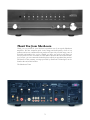
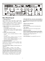
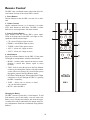
Table of Contents 3 Thank You From Sherbourn 4 Safety Precautions 6 NEC (National Electrical Code) Standards A Note for the 5Cable Television (CATV) Installer Antenna Grounding Outside the House 6 Unpacking Your Sherbourn Preamplifier 7 PRE-1 Preamplifier Features 8 Front Panel Layout 9 Rear Panel Layout 10 Remote Control 11 Connecting Audio Source Units Connecting to Phono, CD, Tuner, Aux1 and Aux2, Tape, HT Input Connecting to Amplifiers and Speakers Trigger Connections 12 Troubleshooting Guide No Sound (from one or more full range speakers) No Low Frequency (or poor output) Sound Drops Out with CD or DVD Playback Remote Not Working External Amplifier(s) Shut Down (often or prematurely) Remotely Connected External Amplifier(s) Do Not Turn Off With PRE-1 “Hum” Noises Other Probable Causes of Speaker Noise Problems with the whole A/V System 13 Licensing and Trademark Disclosures 13 Technical Specifications Thank You from Sherbourn Thank you very much for your decision to purchase one of our superb Sherbourn amplifiers. We take enormous pride in the design and build quality of all of our products and we are confident that our product will provide you with many years of enjoyable and trouble free service. Should you have any need to call upon our services please feel free to contact us at the address shown at the end of this booklet; or, of course, you can contact the dealership from which you purchased the product. Full details of the warranty coverage provided by Sherbourn Technologies can be found at the end of this booklet. The Sherbourn Team 3 Important Safety Precautions and Explanation of Symbols ! The exclamation point within an equilateral triangle is intended to alert the user to the presence of important installation, operation, and service instructions in this manual. The lightning flash with arrowhead symbol within an equilateral triangle is intended to alert the user to the presence of uninsulated dangerous voltages within the enclosure that may be of sufficient magnitude to constitute a risk of electrical shock to the user. Please read this Installation and Operation Manual thoroughly before attempting to install, configure, or operate the PRE-1. After successful installation and configuration of the PRE-1, be sure to retain this manual in a safe place for future reference. Safety is a key component to a long lasting and trouble free installation. Please read and follow all instructions and heed all warnings on the PRE-1 and in this manual. The vast majority of the subsequent safety precautions are common sense. If you are not comfortable with the installation of audio/video entertainment equipment, you should seek the services of a qualified installation professional or call us for help. ! WARNING: TO REDUCE THE RISK OF FIRE OR ELECTRIC SHOCK, DO NOT USE THE PRE-1 NEAR WATER OR IN WET LOCATIONS, DO NOT EXPOSE IT TO RAIN OR MOISTURE, DO NOT EXPOSE IT TO DRIPPING OR SPLASHING FROM OTHER SOURCES, AND ENSURE THAT NO OBJECTS FILLED WITH LIQUIDS (SUCH AS VASES) ARE PLACED ON IT. DOING SO MAY RESULT IN DAMAGE TO THE PRE-1 AND THE RISK OF ELECTRIC SHOCK, WHICH MAY RESULT IN BODILY INJURY OR DEATH. WARNING: TO REDUCE THE RISK OF ELECTRIC SHOCK, DO NOT REMOVE THE COVER FROM THE PRE-1. THERE ARE NO USER-SERVICEABLE PARTS INSIDE THE PRE-1. REFER ALL SERVICE TO QUALIFIED SERVICE PERSONNEL. Do not install the PRE-1 near or above any heat sources such as radiators, heating vents, or other apparatus that produces heat. Do not block any ventilation openings or heat sinks. Avoid installing the PRE-1 directly above other heat-producing equipment unless sufficient ventilation or forced-air cooling is provided. Do not install the PRE-1 in locations without proper ventilation. The PRE-1 should not be operated on a bed, sofa, rug, or similar surface that may block vents. The PRE-1 should not be installed in an enclosed location such as a bookcase, cabinet, or closed equipment rack unless sufficient forced-air ventilation is provided. Always install your PRE-1 according to the manufacturer’s instructions and only use attachments or accessories specified by the manufacturer. Do not install the PRE-1 on any stand, shelf, or other piece of furniture that is unable to support its weight. If a cart is used to move the PRE-1, use caution to avoid injury from tip-over. Connect the PRE-1 only to power sources of the correct voltage (as shown in this manual and on the PRE-1). Ensure that the Input Voltage selector switch on the rear of the PRE-1 is set to the appropriate voltage. Protect power supply cables from being pinched, walked on, or otherwise damaged. Be especially careful where the power cable enters the power outlet and the PRE-1 unit. Only connect the PRE-1 to an electrical outlet or extension cord of appropriate type and rating. DO NOT defeat the safety purpose of a grounding or polarized plug by removing ground pins or using unsafe adapters. A polarized plug has two blades - one wider than the other. A grounding plug has a third ground prong in addition to the two main conductors. The wide blade or third groundling prong is provided for your safety. If the provided plug does not fit your outlet, consult an electrician to replace your obsolete outlet. If you replace the PRE-1 power cord, only use one of similar type and equal or greater current rating. 4 The power cable for the PRE-1 should be unplugged from the outlet during severe electrical storms, or when unused for a long period of time. Only replace the fuse in the PRE-1 with a fuse of proper value and voltage rating. The PRE-1 should only be cleaned as directed in the Installation and Operation Manual. Avoid spraying liquids directly onto the PRE-1 and NEVER spray liquids into the vents. Care should be taken so that small objects do not fall into the inside of the PRE-1. ! You should seek service for your PRE-1 by qualified service personnel if any of the following occur: 1. The power-supply cord or the plug has been damaged 2. Objects or liquid have fallen or spilled into the vents 3. The PRE-1 has been exposed to rain 4. The PRE-1 exhibits a marked change in performance 5. The PRE-1 has been dropped, or its enclosure or chassis is damaged. NOTE: TO COMPLETELY DISCONNECT THE PRE-1 FROM THE AC POWER MAINS, DISCONNECT THE AC POWER CORD FROM THE AC RECEPTACLE. NOTE: THE POWER CORD ON THE PRE-1 MUST REMAIN READILY ACCESSIBLE AT ALL TIMES. CAUTION CAUTION: TO REDUCE THE RISK OF ELECTRICAL SHOCK, DO NOT REMOVE COVER. NO USER SERVICEABLE PARTS INSIDE. REFER SERVICING TO QUALIFIED SERVICE PERSONNEL. FCC Interference Statement Note: This equipment has been tested and found to comply with the limits for a Class B digital device, pursuant to Part 15 of the FCC rules. These limits are designed to provide reasonable protection against harmful interference in a residential installation. This equipment generates, uses and can radiate radio frequency energy and, if not installed and used in accordance with the instructions, may cause harmful interference to radio communications. However, there is no guarantee that the interference will not occur in a particular installation. If this equipment does cause harmful interference to radio or television reception, which can be determined by turning the equipment off and on, the user is encouraged to try to correct the interference by one or more of the following measures: Reorient or relocate the receiving antenna. Increase the separation between the equipment and receiver. Connect the equipment into an outlet on a circuit different from that of the receiver. Consult the dealer or an experienced radio/TV technician for help. For questions regarding service, please contact: Sherbourn Technologies, Inc. 131 SE Parkway Court Franklin, Tennessee 37064 Tel (615) 791-4046 Fax (615) 791-6287 Web www.sherbourn.com 5 NEC (National Electrical Code) Standards Unpacking the PRE-1 All Sherbourn preamplifiers are double boxed to survive the rigors of long distance shipping and arrive to you undamaged. The outer box may show wear and tear, but this is no cause for alarm. The outer box’s purpose is to protect the inner box. If the inner looks heavily damaged, and you are concerned about damage to the preamplifier, please call Sherbourn Technical Support at 615-791-4046. A Note for the Cable Television (CATV) Installer This reminder is to call the CATV system installer’s attention to Article 820-40 of the NEC that provides guidelines for proper grounding and in particular, specifies that the cable ground shall be connected to the grounding system of the building as close to the point of cable entry as practical. Inside the laminated inner box, the preamplifier is securely seated between to two reinforced pieces of high-density impact foam. At first glance, the cardboard backing on the foam may give the appearance of a third box, but it is easily lifted to reveal the preamplifier, which is wrapped in static free plastic. The plastic sheeting is tucked underneath the preamplifier and securely taped. It is recommended that the plastic sheeting be removed after the amp is lifted out from the box. Antenna Grounding Outside the House If an outside antenna is connected to the receiver, be sure the antenna system is grounded so as to provide some protection against voltage surges and built-up static charges. Article 810 of the National Electrical Code, ANSI/NFPA 70, provides information with regard to proper grounding of the lead-in wire to an antenna-discharge unit, connection to grounding electrodes, and requirements for the grounding electrode. See diagram below. The bottom piece of foam is molded to fit tightly against the preamplifier, but there is a recessed area on each side, allowing you to get your hands under the preamplifier and lift it out of the box. Inventory: Included with your PRE-1 preamplifier should be an IEC Class 1 two prong power cord and this manual. It is important to save all the packing materials and the boxes in case your PRE-1 ever needs to be moved or shipped back to the factory for service. Make sure you keep your sales receipt. It is the only way for Sherbourn to establish the duration of your Limited Warranty and it may come in useful for insurance purposes. Cable TV Coaxial Cable, Satellite Dish Cables and Television Antennas should be grounded BEFORE the point of entry into the house. Recording the Serial Number Please read the serial number located on the rear panel and record it below along with the date of purchase. Always observe proper antenna or satellite dish grounding techniques. When lightning strikes, there is always the possibility that your antenna or dish (mounted high on the roof) can become a conduit for lightning and electrically damage any equipment to which it’s connected. Additionally, proper grounding offers safety to the people using the audio/video system in the event of an electrical problem. 6 Model PRE-1 Serial Number ____________________ Place of Purchase ____________________ Date of Purchase ____________________ PRE-1 Features Precision low noise phono input with moving magnet or moving coil capability Seven stereo inputs with precision instrumentation grade relay switching Microprocessor controlled pure analog signal path Full remote control operation Gold plated discrete RCA connectors for all inputs and outputs Tape monitor loop Home Theater Bypass Stereo / Mono switching Large format precision film volume potentiometer with motorized control Headphone output Illuminated input indicators 12V trigger output I EC power inlet, 120/230 VAC user configurable 7 Front Panel Layout Input Indicator LEDs LEDs above each selectable button illuminate when the labeled function is engaged. All of the labeled indicators are available as remote commands. 9. Mono Button Push to combine left and right (L+R) channels of the PRE1. 10. Tone Button Activates or bypasses use of treble and bass controls. 1. I/R Receiver Window Point the remote at this window for operation of the PRE1 by remote. 11. Mute Button Push to mute the PRE-1. 2. CD Player Source Selection Button Selects a properly connected CD Player as input source. 12. Power Button and standby LED The power button is a non-latching momentary button that turns the PRE-1 on or off. On indicates with a blue LED. Off indicates with red LED. 3. Tuner Source Selection Button Selects a properly connected Tuner as input source. 4. Auxiliary 1 Source Selection Button Selects any 2 channel audio device with analog outputs connected to the AUX 1 inputs as input source. 13. Headphone Jack Standard 1/4” gold-plated headphone jack is provided on the front panel. 5. Auxiliary 2 Source Selection Button Selects any 2 channel audio device with analog outputs connected to the AUX 2 inputs as input source. 14. Bass Control Knob Increases or decreases bass level. 6. Phono Source Selection Button Selects a properly connected turntable as input source. 15. Treble Control Knob Increases or decreases treble level. 7. Tape Monitor button This ‘loop’ connects an external recording device to the PRE-1 Preamplifier via RCA outputs and inputs. While this traditionally has been a cassette player or DAT player, this connection could also be a hard drive based recording device as long as the input and output connections are analog RCA audio connections. 16. Motorized Volume Control Knob Motorized precision film pot volume control is adjustable manually or with remote. 8. HT Bypass Button Push to bypass all of the preamp functions of the PRE-1, allowing the PRE-1 to be a pass through. 8 Rear Panel Layout NOTE: HT INPUTS are only active when the PRE-1 is on. ALL PRE-1 functions become disabled in HT BYPASS mode, allowing the external processor to control volume, EQ, etc. 1. TRIGGER OUTPUT Allows a mono to mono 3.5mm cable to remotely trigger another device on and off, along with the PRE-1. Current is limited to 500mA, which is sufficient to trigger two devices. For triggering more devices, you may want to use a separate triggering device, like the Sherbourn ET-3. AUDIO OUTPUT SECTION 6. Balanced Output Balanced (XLR) connection for left and right speakers. 2. PHONO INPUT Section (clockwise from top left) • Phono Ground • Left and Right channel RCA inputs • MC/MM Switch. Use this switch to select your cartridge type. MC for Moving Coil or MM for Moving Magnet. 7. RCA Outputs Standard RCA connections for left and right speakers. 8. Main Power Switch This rocker switch provides the master power for the PRE-1. After it is in the ON position, the PRE-1 can be turned on manually from the front panel switch, remote control, or automatically with the trigger input via a 3.5mm input jack. 3. AUDIO Section (from left to right) • CD Player inputs (Switchable Balanced or Unbalanced) • Tuner inputs • Auxiliary 1 inputs - Suitable to connect to any audio device with Left and Right analog outputs. • Auxiliary 2 inputs - Suitable to connect to any audio device with Left and Right analog outputs. 9. Power Receptacle Uses standard IEC power cord. 4. TAPE INPUT/OUTPUT A tape loop is provided for recording 2-channel source material from a Cassette, DAT or a Hard Disk Audio device with analog outputs. 5. HT INPUT (Home Theater) Switchable Balanced or Unbalanced Allows the PRE-1 to connect to an external multichannel/home theater processor. This connection is disengaged when the PRE-1 is in normal mode, but becomes active when the HT BYPASS button is selected on either the PRE-1 front panel or remote control. In HT BYPASS mode, this connection becomes active and the PRE-1 becomes a pass-through. This is a true 'straight wire' pass-through - what comes in is what goes out. 9 Remote Control The PRE-1 has a dedicated remote control that offers discrete buttons for most of the critical PRE-1 controls. 1. Power Buttons Discrete buttons to turn the PRE-1 on and off, as indicated. 2. Volume Controls Applies continuous increase (+) or decrease (-) in volume levels while buttons are held down. The PRE-1 volume knob moves in correspondence with these controls. 3. Source Selection Buttons These buttons select the various PRE-1 source inputs. LEDs on the front panel of the PRE-1 will light in correspondence with the selected input. • CD - selects CD player input as source. • PHONO - selects Phono input as source. • TUNER - selects Tuner input as source. • AUX 1 - selects Aux 1 input as source. • AUX 2 - selects Aux 2 input as source. 4. Mode Buttons Select the indicated function for the PRE-1. Front panel LEDs light in correspondence with the selected mode. • MONO - switches audio output from stereo to mono. Pressing a second time restores signal to stereo (default). • TAPE - Push to select the inputs on the Tape Monitor section to pass through the outputs of the tape monitor section. When not selected, any selected input passes through the output of the Tape Monitor output. • HT (Home Theater Bypass) -When pushed, the HT Input connections will pass through the PRE-1, bypassing the PRE-1 completely. PRE-1 • TONE – Allows one to activate or deactivate the bass/treble controls. • MUTE - mutes the PRE-1. Changing the Battery The PRE-1 remote is powered by 2 AAA batteries. To add fresh batteries, press in the battery cover tab, remove the battery cover, exchange the batteries and orient the negative and positive ends as indicated by the images in the battery compartment. Sherbourn recommends using alkaline batteries. 10 Connecting Audio Source Units AUX1 & AUX2 These inputs can be used with most 2 channel audio source devices, including DVD players, personal computers, portable media players, MP3 players/docks, etc. Depending on the type of media player and/or docking station available, direct RCA outputs may not be available, so a 1/8" stereo mini jack to RCA adapter may be necessary to complete the connection. Analog outputs on the audio devices are necessary to connect to the PRE-1. The PRE-1 can connect to up to seven different audio devices, using standard RCA analog connectors. PHONO Connects to a turntable using standard RCA type connectors. Connect the Left output on the turntable to the Left input of the PHONO INPUT section on the PRE-1, and the Right output to the Right input of the PHONO INPUT section of the PRE-1. TAPE This 'loop' connects an external recording device to the PRE-1 preamplifier via RCA outputs and inputs. While this traditionally has been a cassette player or DAT player, this connection could also be a hard drive based recording device as long as the input and output connections are analog RCA audio connections. Also note the connection of the chassis ground tab between the turntable and preamplifier. This is necessary for audio signal reference so the PRE-1 processes signal from the turntable with minimal unwanted noise. Select the type of cartridge, either high output Moving Magnet (MM) or low output Moving Coil (MC) by moving the switch to the appropriate positions. To enable the tape monitor loop you must connect to the inputs AND outputs on the PRE-1 labeled "TAPE" on the rear panel. To engage the tape monitor loop, select TAPE from the PRE-1 front panel or remote. If you are not sure which type of cartridge you have, select MM first and then if the noise level is too high, try selecting MC instead. Please note -these outputs are unaffected by any external signal processing. The PHONO input is not designed for line level sources such as CD players or other devices. Please ONLY connect turntables with Moving Magnet or Moving Coil needle cartridges to this input to avoid damage. To engage the recording device, first press TAPE from the front panel or remote and then it will allow you to "monitor" the audio that the recording device will record. When you are ready to record, engage the recording device. If you are using a separate preamplifier for your turntable, do not use the PRE-1 Phono input section. Use either the AUX1 orAUX2 inputs. The PRE-1 Phono input is a high gain input, and turntable preamplifiers have high gain output. Combining the two would result in an extremely high gain signal that would cause unwanted distortion. HT INPUT Connects to an external multi-channel, or 'home theater' processor using standard RCA type analog connectors. When the HT BYPASS button is selected, all PRE-1 functions are disabled, and it becomes a pass-through for the connected external processor. The HT inputs are only active when the PRE-1 is on. CD Connects to a CD player using standard RCA type connectors. Connect the Left output on the CD player to the Left input of the CD INPUT section of the PRE-1, and the Right output on the CD player to the Right input of the CD INPUT section of the PRE-1. * This is not a dedicated input, and can be used as an input for a device other than a CD player. Connecting To Amplifiers and Speakers When connecting to amplifiers and speakers, make sure to use the properly labeled connections. Check to make sure that you have connected the proper cables in the proper sequence: • Left and right channel PRE-1 outputs into left and right channel amplifier inputs. • Left and right channel amplifier outputs to left and right speakers. TUNER Connects to a Tuner using standard RCA type connectors. Connect the Left output on the Tuner to the Left input of the TUNER section of the PRE-1, and the Right output on the Tuner to the Right input of the TUNER section of the PRE-1. * This is not a dedicated input, and can be used as an input for a device other than a Tuner. NOTE: Do not connect speakers directly to the PRE-1. 11 Also use high quality, 100% shielded, oxygen free copper cables. less than your amplifiers can safely handle. • The amplifier(s) have good ventilation, no vents are covered. • Check that the amplifier(s) power output is a good match for your speakers. If your speakers are inefficient, consider using larger power amplifiers. • Make sure all wiring is correct and there are no shorts. If wires have been run under carpet, under base boards (or along tack strips) there is a possibility they can easily be shorted by sharp edges or something that punctures the insulation. Also, if your wiring is in the walls - make sure that there was not an accidental "staple" puncture from securing wiring to framing studs or wall/floor joists. This evaluation is easily done with an Ohm meter. Trigger Connections 12VDC trigger used to remotely trigger a connected device on and off. Please ensure that the total of the loads connected to this trigger do not exceed 500mA. Troubleshooting Guide The Sherbourn PRE-1 is expertly designed and built to provide years of trouble-free performance. Most problems that occur can usually be solved by checking your connections or making sure that the audio and video components connected to the PRE-1 are on and fully operational. The following information will help you deal with common problems you may experience during initial use of your unit. If problems persist, contact Sherbourn’s service department for assistance. Remotely Connected External Amplifier(s) Do Not Turn Off with PRE-1 Check the following: • Make sure the 1/8" plug is connected between PRE-1 trigger output and the amplifier(s) trigger input(s). • Make sure the total consumption of the connected devices do not exceed 500mA • If you have spliced the plug to one or more amplifier turn on inputs, remember the center pin is positive and the outer shield is negative. This output is 12VDC. No Sound (from one or more full range speakers) • Speaker cables may have come undone from the amplifier. Turn off your system and check the speaker cables, and tighten the binding posts. • Audio output cables that connect PRE-1 to the amplifier(s) may not have a good connection. Turn off your system and check all audio cable connections. • An audio cable may have an internal break. Switch cable with a different channel to see if the problem migrates to a different channel or stays in the affected channel(s). • The correct input is not currently selected. • The mute switch is on. Sound Drops Out with CD or DVD Playback • Make sure the disc is not dirty or scratched. • Some inexpensive players and changers tend to mistrack more often than you would like. "Hum" Noises This problem is more than likely caused by a "ground loop" in your system, rather than a fault in the PRE-1. Follow these steps to isolate the main cause of the hum; there may even be more than one. Remember to turn off all components in your system (including the PRE-1) before disconnecting or connecting any cables. Disconnect the following items in order, and check each time if the hum has gone away: • Disconnect all cables which come from outside the room, such as cable TV, satellite TV, or roof top antennas. Make sure that they are disconnected where they first enter the room, so they are making no connection to the PRE-1, the TV, or any other component. If the hum is caused by the cable TV line, you will need a "ground loop isolator." This is an inexpensive device fitted in-line with the coaxial cable feed. Contact your cable company or your Sherbourn Dealer for assistance. • Disconnect any component which has a grounded power cord. • If the hum persists, disconnect all the source components one at a time from the back of the PRE-1 until you identify the problem. (Ground loop isolators are available for audio lines and video. Ask Sherbourn Remote Not Working • Make sure the AAA batteries are not dead or installed incorrectly. • Make sure that the PRE-1 front panel receiver window is not obstructed. External Amplifier(s) Shut Down (Often or Prematurely) • Make sure each speaker's average impedance is not 12 for assistance) • Try moving the speaker cables away from any power cords. Try just one speaker, connecting it to different channels and see if an amplifier channel is bad. • If you are still having a problem, remember that Sherbourn's technical support staff will assist you. Technical Specifications Preamp Audio Section Phono Input: Moving Coil – 240 ohm Moving Magnet – 47k ohm Other Probable Causes of Speaker Noise • Speaker noise may also be caused by interference or noise on your AC line. Make sure there are no large appliances sharing the line, halogen lamps, or light-dimming Triac devices. • Try connecting your system to another AC socket on a separate line. • If the hum is heard from within the PRE-1 and not through the speakers, this may also be caused by interference on the AC or DC lines. The power transformers may turn this interference into an audible noise. Internal hum can be made worse by a shelf or cabinet resonating, so try moving the PRE-1 to another shelf. • Try moving your components further away from the TV, especially if you ever notice the screen has changed color in the area closest to the component. • If you have very high efficiency speakers, these may tend to reveal noises which other speakers do not. Input Impedance Line In: 47K ohm +/-5% Problems with the whole A/V System If you are having more complex problems in your overall home entertainment system (not just with the PRE-1 preamplifier/processor), please contact Sherbourn directly for professional installation assistance. These professionals have years of experience with a wide range of home entertainment and products and can offer you assistance in troubleshooting and rectifying problems. Other Details Signal-to-Noise Ratio (rel 2V out): >116dB (ref 2V) Distortion: < 0.005% 20Hz - 20kHz with 80kHz measurement bandwidth Frequency Response: 5Hz - 80kHz +/- 0.05 dB 5Hz - 250kHz +/- 1 dB Maximum Line Out Level: 9V RMS Ground Floor Noise Level: > 20uV Channel Separation @ 1kHz: > 80dB Trigger Output: 12 VDC, 3.5mm jack, Center Pin is Positive / Current Load <120mA Electrical Power Requirement: 115VAC, 60Hz or 230VAC, 50-60Hz User Selectable Raw Weight: 14 Ibs Dimensions: Width: 17 inches Depth: 14 inches (including RCA jack extension) Height: 3.75 inches (faceplate only) - 4.25 inches including feet Licensing and Trademark Disclosures Sherbourn Disclosure All Rights Reserved. Sherbourn reserves the right to make improvements to its products at any time. Therefore, the specifications of the product and the specific details of this manual are subject to change at any time. 13 Sherbourn Technologies, LLC Ten-Year Limited Warranty What does this warranty cover? Sherbourn Technologies, LLC (“Sherbourn”) warrants its products against defects in materials and workmanship. This warranty is subject to revision at any time. How long does this coverage last? This warranty commences on the date of retail purchase by the original retail purchaser and runs for a period of ten (10) years thereafter, with the following exceptions: (1) receivers (including the SR-8100, SR-8200, and SR-120), preamp/processors (including the PT-7030, PT-720C4, and PT-7020), preamplifiers (including the PRE-1), and the CD-1 CD Player (with the exception of the slot load CD engine) are covered by this warranty for five (5) years from the date of retail purchase by the original purchaser; and (2) electromechanical components, including the slot load CD engine on the CD-1 CD Player, and all fans (including the C-12 Cooling Unit), are covered by this warranty for three (3) years from the date of retail purchase by the original retail purchaser. This warranty is transferrable, upon written notification to Sherbourn, to any person that owns the warranted product, however, if ownership is transferred, the Term shall be no longer than five (5) years from the date of purchase by the original purchaser. Sherbourn warrants any replacement product or part furnished hereunder against defects in materials and workmanship for the longer of the following: (i) the amount of time remaining under the original warranty, or (ii) 120 days from your receipt of the repaired or replaced product. The duration described in the previous 3 sentences is hereinafter referred to as the “Term”. TO THE FULLEST EXTENT PERMITTED BY LAW, ALL IMPLIED WARRANTIES RELATED TO THE ORIGINAL PRODUCT AND ANY REPLACEMENT PRODUCT OR PARTS (INCLUDING IMPLIED WARRANTIES OF MERCHANTABILITY AND FITNESS FOR A PARTICULAR PURPOSE) ARE EXPRESSLY LIMITED TO THE TERM OF THIS LIMITED WARRANTY. SOME STATES DO NOT ALLOW LIMITATIONS ON HOW LONG AN IMPLIED WARRANTY LASTS, SO THE ABOVE LIMITATION MAY NOT APPLY TO YOU. A claim under this warranty must be made by you within the Term. A claim shall not be valid (and Sherbourn has no obligation related to the claim) if it is not made within the Term and if it is not made in strict compliance with the requirements of the “How do you get service?” section. What will Sherbourn do? Sherbourn will, at its option, either: (i) repair the product, or (ii) replace the product with a new consumer product which is identical or reasonably equivalent to the product. Sherbourn may provide you with a refund of the actual purchase price of the product in the event (i) Sherbourn is unable to provide replacement and repair is not commercially practicable or cannot be timely made, or (ii) you agree to accept a refund in lieu of other remedies hereunder. When a product or part is repaired or replaced, any replacement item becomes your property and the replaced item becomes Sherbourn’s property. When a refund is given, the product for which the refund is provided must be returned to Sherbourn and becomes Sherbourn’s property. What is not covered by this warranty? This warranty does not apply: (i) to damage caused by use with non-Sherbourn products, where the non-Sherbourn product is the cause of the damage; (ii) to damage caused by service or maintenance performed by anyone who is not a representative of Sherbourn; (iii) to damage caused by accident, abuse, misuse, flood, fire, earthquake or other external causes; (iv) to a product or part that has been modified after its retail purchase, where the modification caused or contributed to the damage; (v) to consumable parts, such as batteries; (vi) normal wear tear; or (vii) if any Sherbourn serial number has been removed or defaced and Sherbourn cannot otherwise confirm that you are the original retail purchaser or authorized transferee. SHERBOURN SHALL NOT BE LIABLE FOR ANY INCIDENTAL OR CONSEQUENTIAL DAMAGES ARISING FROM OR RELATED TO ANY DEFECTS IN OR DAMAGES TO ITS PRODUCTS. SOME STATES DO NOT ALLOW THE EXCLUSION OR LIMITATION OF INCIDENTAL OR CONSEQUENTIAL DAMAGES, SO THE ABOVE LIMITATION OR EXCLUSION MAY NOT APPLY. How do you get service? In order to make a claim under the warranty, you must: 1. Call a customer service representative (“CSR”) of Sherbourn at (1-877-366-8324). Provide the CSR with a description of your problem and the serial number of the product for which the warranty claim is being made. 2. The CSR will provide you with a returned material authorization number (“RMA”). 3. Ship the product to Sherbourn at the following address, with the RMA written in large, bold letters on the outside of the box, and with the letters “RMA” written before the number. Parcels arriving without an RMA number on the outside of the box will be refused. Sherbourn Technologies, LLC Attn: Repair Department 131 Southeast Parkway Court Franklin, TN 37064 How does state law apply? This warranty gives you specific legal rights, and you may also have other rights which vary from state to state. CERTAIN STATES HAVE ENACTED LAWS WHICH PRECLUDE THE WAIVER OF CONSEQUENTIAL AND INCIDENTAL DAMAGES AND/ OR PRECLUDE THE WAIVER/LIMITATION OF IMPLIED WARRANTIES. TO THE EXTENT YOUR STATE HAS ENACTED A LAW WHICH PROHIBITS SUCH A WAIVER/LIMITATION, ALL SUCH WAIVERS/LIMITATIONS CONTAINED IN THIS WARRANTY ARE INAPPLICABLE TO YOU. CERTAIN STATES HAVE ENACTED LAWS WHICH REQUIRE THE DURATION OF A WARRANTY TO BE EXTENDED (INCLUDING BUT NOT LIMITED TO DURING PERIODS OF REPAIR). TO THE EXTENT YOUR STATE HAS ENACTED A LAW OF THIS NATURE, THEN THE DURATION OF THIS WARRANTY WILL BE EXTENDED AS REQUIRED BY APPLICABLE LAW.