1
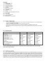
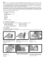
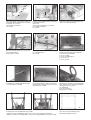
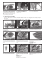
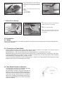
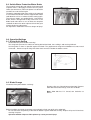
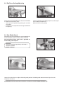
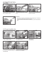
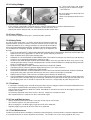
Assembly/Operating Instructions
Site Saw BKS 400/BKS 450
Model No. 1001
3305
Stock-no. 115 107 8059
Contents
1.0
2.0
3.0
4.0
5.0
6.0
7.0
8.0
9.0
10.0
11.0
12.0
13.0
14.0
15.0
16.0
Scope of Application
Specifications
User Responsibility
Standard Accessories
Optional Accessories
Assembly
Mitre Fence Assembly
Installation
Operation/Settings
Cutting
Saw Dust Collection (optional accessory)
Crane Lifting
Safety Rules
Care and Maintenance
Wiring Diagrams
Spare Parts List and Drawing
1.0 Scope of Application
- This site saw model BKS 400/BKS 450 has been designed to perform rip and cross cuts in wood having a
square or rectangular cross section.
- Cross cuts should only be performed with the help of the mitre fence.
- Round stock or firewood should not be cut without an appropiate jig holding the work safely.
- The maximum/minimum blade diameters are 400/350 mm for model BKS 400 and 450/350 mm for model
BKS 450.
2.0 Specifications
Table size
Table height from floor
Depth of cut
Motor speed 50/60 Hz
Cutting speed
Motor capacity P1 S6 40%
Motor capacity P2 S1 100%
Voltage
Mains fuse
Max. saw blade diameter
Min. saw blade diameter
Saw blade bore
BKS 400/3.1 WNB
BKS400/4.2 DNB
BKS450/4.75DNB
1000 x 665 mm
850 mm
127 mm
2800/3360 rpm
58.5 m/sec
3.1 kW
1.5 kW
1~ 220/240V
1 x 16A
400 mm
350 mm
30 mm dia.
1000 x 665 mm
850 mm
127 mm
2800/3360 rpm
58.5 m/sec
4.2 kW
2.1 kW
3~ 380/440V
3 x 16A
400 mm
350 mm
30 mm dia.
1000 x 665 mm
850 mm
152 mm
2800/3360 rpm
66 m/sec
4,75 kW
2.4 kW
3~ 380/440V
3 x 16A
450 mm
350 mm
30 mm dia.
Note: Saw blade 450mm diameter requires 4.75kW motor. Use of 450mm blades with 3.1kW and 4.2kW
motor voids factory warranty!
3.0 User Responsibility
This machine will perform in conformity with the description contained in the instructions provided. This machine must
be checked periodically. Defective equipment (including service leads) should not be used. Parts that are broken,
missing, plainly worn, distorted or contaminated, should be replaced immediately. Should such repair or replacement
become necessary, it is recommended that such repairs are carried out by qualified persons approved by the equipment
manufacturer or its representative. This machine or any of its parts should not be altered or changed from standard
specifications. The user of this machine shall have the sole responsibility for any malfunction which results from
improper repair by anyone other than qualified persons approved by the equipment manufacturer or its representatives.
Note
Within the U.K., this machine falls under the Woodworking Machinery Regulations 1974, under which certain
operations, e.g. grooving, rebatting, tenoning and moulding are prohibited without special guards. For your own safety
it is recommended to follow the instructions given in the Health and Safety at Work booklet No.41, entitled “Safety in
the Use of Woodworking Machines” and “A Guide to Woodworking Machinery Regulations” HS(R)9. Both publications
are available from Her Majesty’s Stationary Office and other bookshops.
The information contained in this manual is intended to make the operator of this saw familiar with its safety features,
setting of guards and fences, and the safe performance of the different basic cutting operations normally carried out
with this type of saw. It does not teach the operator how to become an expert woodworker. Those persons interesting
in gaining a more intimate knowledge on the tasks which can be carried out on this type of saw are advised to refer to
commercially available literature on the subject.
4.0 Standard Accessories
-
Saw blade
Riving knife DIN 38820 Gr. 50x3
Saw blade guard
Rip fence
Mitre fence
Lifting eyes
Push stick
Tool set
Operating instructions
5.0 Optional Accessories
For the metabo Site Saws BKS the following accessories are available at extra cost:
- Sliding Carriage BKS/BKH
Stock-no. 0910 00666 5
- Extension Table BKS/BKH
Stock-no. 0910 00667 3
- Dust Extraction Adaptor BKS 100mm
Stock-no. 0910 00874 9
- Log Cutting Attachment BKS/BKH
Stock-no. 0910 00886 2
6.0 Assembly
Place table onto firm support (e.g. saw horses).
Attach table insert (aluminium extrusion) to table; use 10 pcs. countersunk flat-head screw 4.2x13. Bolt rip fence guide
extrusion to front of table.
Bolt both support brackets to the motor. Use 4
each hex. head screw M8x16 hex. nut M8.
Attach the thus preassembled motor to the
table, but do not yet tighten fully. Use 4 each
countersunk screw M8x16
hex.nut M8
washer 8.4
Install saw blade onto motor, than align motor
so that the saw blade is centered in the table
insert’s slot.
When positioned correctly fully tighten the
motor on the table.
Attach mounting plate for the riving knife carrier bracket to the table.
Use 4 each
countersunk screw M6x16
hex. nut M6
top
Attach riving knife carrier bracket loosely to
mounting plate.
Use 4 each
hex. head screw M6x16
washer 6.4
hex. nut M6
Place carriage bolt M12x30 into slot of carrier
braand slide riving knife carrier onto bolt. The
imprint “Oben” must point towards the table.
Mount riving knife and secure in place with
pressure plate and self-locking hex. nut M12.
Align riving knife with saw blade, then fully tighten the screws ficing the riving knife carrier
bracket to the mounting plate.
90°
Place both support struts onto the table, set
square with the slot of the table insert and bolt
to the table. Use 10 each
countersunk screw M6x16,
hex. nut M6
Install the guard support bracket without fully
tightening the screws.
Use 2 each
countersunk screw M6x16, hex. nut M6,
hex. head screw M8x16,
hex. nut M8
Attach gusset plate with carriage bolt M10x25,
washer 10.5 and starknob M10
Bolt switch to front support strut. Use 2 each
hex. head bolt M6x16
torque type hex. nut M6
Attach strain relief clamp to support strut. Use
hex. head bolt M6x16
hex. nut M6
Remove saw blade and bolt chip case to both
support struts and motor plate. Hardware:
4 ea. hex head screw M8x16
4 ea. hex. nut M8
2 ea. hex. head bolt M6x16
2 ea. washer 6.4
2 ea. hex. nut M6
Install both hex. head bolts M8x90 into chipcase, secure with hex. nuts M8
Re-install saw blade, be sure of correct direction of rotation. Install chip case lid. Use 2 each
torque type hex. nut M8
Bolt lifting eyes to table (at rear left and front
right). Place pressure spring onto bolt before
screwing on nut. Use 2 each
hex. bolt M8x35
pressure spring 9x20
torque type hex. nut M8
"A"
Install legs with struts and diagonal struts to table.
- Tighten all screws handtight only at this stage. - Install struts as shown in drawing “A”.
Hardware: 22 each hex. head bolt M8x16; 4 each hex. head bolt M8x20; 26 each hex. nut M8
Turn saw over and stand onto its legs.
Align and fully tighten all screws.
Place guard support into guard support brakket. Align with blade and riving knife and to
exact 90 against the table by moving the not
yet fully tightened guard support bracket. Tighten.
Note: An improperly set up guard support may
cause personal injury to the operator.
Install the hex. socket head screw holding the
push stick to the front left leg. Hardware:
1 hex. socket head screw M6x30
2 each hex. nut M6
Install bolt for holding the rip fence to front right
leg. Use hex. nut M8 and bolt M8
7.0 Mitre Fence Assembly
- Cross cuts and mitre cuts must not be carried out without a suitable cross-cutting attachment (sliding carriage or
mitre fence).
If no mitre fence is installed use the Sliding Carriage stock-no. 091 000 06665.
Bolt guide rod brackets to front and rear of
table. Use 4 each
hex. head bolt M8x16
hex. nut M8
Slide both plastic guide bushes onto guide rod,
then bolt guide rod to brackets. Use 2 hex.
head bolts M8x20.
Bolt mitre fence carrier to guide bushes. Use 8
raised countersunk tapping screws 4.8x22.
Screw vernier scale carrier to mitre fence carrier with raised countersunk head tapping screw
4.8x13
Screw vernier scale to vernier scale carier with
2 each raised countersunk head tapping screw
2.9x6.5
Install adjustable backstop on mitre fence segment. Hardware:
1 hex. head bolt M6x20
2 hex. nut M6
1 washer 6.4
Place wave spring washer onto fitting bolt and
plastic glide piece into mitre fence carrier.
Place mitre fence segment onto carrier and
screw fitting bolt through segment into glide
piece.
Hardware:
fitting bolt SW 19x42
spring washer 12
plastic glide piece with threaded bush.
Attach mitre scale to segment using 3 each
tapping screw 3.9x9.5
washer 4.3
Place carriage bolt M10x30 from underneath
through carrier and slot of fence segment.
Install washer Ø 10.5 and ratched lever M10
female.
Install 0° (90°) setting screw into mitre fence
carrier.
Hardware:
1 set screw M8x20
2 hex. thin nut M8
7.1 Mitre Fence Setting
A
To set mitre fence square with the blade turn
setting screw in or out, as required.
B
Make trial cut to verify setting.
C
Loosen mitre scale and adjust so that zero
mark corresponds with mark on vernier scale,
then retighten.
8.0 Installation
8.1 Setup
This saw must be placed on a firm and level ground. The work area must be kept clear of all waste to provide firm
footing for the operator.
8.2 Connection to Power Mains
- Check if voltage of power mains matches with voltage stated on machine’s name plate. This machine must be
earthed while in use to protect the operator from electric shock.
- Models BKS400/3.1 kW must be connected to an earthed outlet with a 3-conductor mains lead.
- Models BKS 450/4.2 kW and 4.75 kW have to be connected to an earthed outlet with a 5-conductor mains lead.
- A minimum conductor cross section of 1.5mm /16 AWG is required. For the 3.1kW single-phase motor extension
cords should have a conductor cross section of 2.5mm .
- Use of an extension cord with too small a conductor cross section causes voltage drop and consequently starting
problems and excessive heat build-up in the motor.
8.3 Saw Blade Direction of Rotation
-
-
On single-phase machines the saw blade’s direction
of rotation does not need to be checked.
For three-phase machines start saw briefly with all
guards in place and check direction of rotation. If
incorrect interchange two phases by rotating two pins
in the switch by 180°. Remove plug, use screwdriver
with 6mm/1/4" blade to push lock down and turn pins.
To prevent unauthorized use the switch can be blokked with a padlock.
8.4 Switch/Motor Protection/Motor Brake
The magnetic switch does not engage if not connected
to power mains. It disengages in the event of a power
failure (no-volt release). When the power is restored the
machine has to be started again.
The built-in motor protection relay switches the motor off
in case it becomes too hot. If this has happened let motor
cool down for at least 10 minutes before starting again.
Three-phase motors are equipped with a mechanical
brake, which is designed for a long service life. If the
blade needs more than 10 sec. to come to a complete
standstill the brake has to be replaced. Check with your
metabo dealer for replacement.
An inoperative motor brake increases danger of injury!
9.0 Operation/Settings
9.1 Riving Knife Setting
-
Disconnect from power before servicing!
The riving knife prevents the work from closing behind the blade, thus stalling it and causing kickback.
Set riving knife as close as possible against the blade. The gap between riving knife and blade must not exceed
10mm/3/8 “. Do not set top of riving knife lower than 2mm-5/64” below the blade’s crown.
9.2 Blade Change
Disconnect from power before servicing!
Remove chip case lid and loosen arbor bolt. Remove
arbor bolt and counter flange, then take off blade.
Note: Arbor bolt has L.H. thread, turn clockwise to
loosen.
Before installing new blade clean blade seat and apply a light coat of oil to the arbor bolt.
- Be sure that teeth are pointing in direction of rotation. Tighten arbor bolt carefully. Replace chip case lid and nuts
securing it in place.
Operation without chip case lid in place may cause personal injury!
9.3 Rip Fence Setting/Adjusting
Set rip fence to required width of cut. Distance from blade
is shown on the rip fence scale.
- Lock rip fence in position by pushing the cam-lock
lever down.
- If rip fence is not required it can be hung to the bolt on
the right leg.
Loosen scale fixing screw to adjust rip fence scale to give
exact reading of width of cut.
Make trial cut to verify setting.
9.4 Saw Blade Guard
After loosening the starknob on the guard support brakket the complete guard assembly can be removed.
Risk of personal injury when saw is operated without blade guard in place!
Attention!
Remove/install blade guard only with blade at
complete standstill.
Danger of injury!
Loosen the ratched lever to adjust the blade guard position. Set blade guard about 8mm/3/8“ higher than the
workpiece’s thickness.
Attention! Set blade guard only with blade at complete standstill. Danger of injury!
10.1 Ripping/Through Sawing
10.0 Cutting
Have riving knife and blade guard in
place - danger of injury.
Set blade guard to thickness of workpiece.
Set rip fence to desired width of cut
and lock in position.
Important!
-
Have blade at complete standstill before making adjustments - Disconnect
machine from power before setting riving knife
If width of cut is less than 120mm-41/2” always use a push stick to feed the
work
10.2 Through Cross/Mitre Cuts
A - Have riving knife and blade guard
in place - danger of injury.
D - Push mitre and work forward to
feed into blade
B - Swing mitre fence onto table and
set to required angle
E - When cut is completed pull back
both mitre fence and work
C - Pull mitre fence back and place
work against it.
- Start machine
10.3 Cutting Wedges
A - Place work firmly into wedge
cutting jig and set to desired angle.
- Start machine
B - Push mitre fence forward to feed
work into blade.
When cut is complete pull mitre fence
back.
11.0 Saw Dust Collection (optional accessory)
-
If this machine is operated in enclosed spaces it must be connected to a saw dust collection device.
The dust collection device must have a minimum air flow rate of 20 m/sec.
Connection to dust collector with 100 mm/4" diameter flexible suction hose.
12.0 Crane Lifting
For crane lifting swing both lifting eyes, attached to table, upwards.
13.0 Safety Rules
As with all power tools there is a certain amount of hazard involved with the
operator and his use of the machine. Using the machine with the respect and
caution demanded as far as safety precautions are concerned will considerably lessen the possibility of personal injury. If, however, normal safety precautions
are overlooked or completely ignored, personal injury to the operator can
develop.
FOR YOUR OWN SAFETY; READ AND UNDERSTAND INSTRUCTION MANUAL BEFORE OPERATING THE
1.
SAW:Learn the saw’s applications as well as the specific hazards peculiar to it.
KEEP GUARDS IN PLACE and in working order.
2.
REMOVE ALL ADJUSTING KEYS AND WRENCHES: Form habit of checking to see that all keys and adjusting
3.
wrenches are removed from tool before switching it “ON”.
ALWAYS USE SAW BLADE GUARD AND RIVING KNIFE for every operation for which they can be used,
4.
including through sawing. Through sawing operations are those when the blade cuts completely through the work
piece as in ripping or cross cutting.
ALWAYS HOLD WORK FIRMLY AGAINST RIPFENCE OR MITRE FENCE.
5.
USE PUSH-STICK if distance between blade and rip fence is less than 120mm/5".
6.
NEVER PERFORM ANY OPERATION “FREE-HAND”.
7.
NEVER REACH BEHIND, OVER OR UNDER THE CUTTING TOOL WITH EITHER HAND FOR ANY REASON.
8.
Keep hands away from saw blade; do not reach into area 120mm left and right of saw blade.
9.
DIRECTION OF FEED: Feed work into saw blade against direction of rotation only.
10. AVOID KICKBACKS (work thrown back at you) by keeping the rip fence parallel to the blade, keeping riving knife
and guards in place and operating, by not releasing work before it is pushed all the way past the saw blade, and
by not ripping stock that is twisted or warped or does not have a straight edge to guide along the fence.
13.1 Problems
-
If saw blade is stalled by waste, or the discharge port of the chip case clogged, switch machine off and let blade come
to a complete standstill before attempting to remove obstruction.
Switch motor off immediately if blade has stalled. A dull blade is most often the cause for what appears to be a loss
of power of the motor.
An extremely dull blade leaves burn marks in the kerf. Replace or resharpen at once.
After a power failure the machine has to be switched on again.
14.0 Care and Maintenance
-
Always disconnect from power before servicing. Do not rely on switch alone.
This machine requires very little maintenance
When changing the saw blade apply a light coat of oil to the arbor bolt.
Regularly apply a light coat of oil to the mitre fence guide rod.
14.1 Tool Maintenance
Residue resin built-up on the saw blade(s) should be removed regularly. Immerse blade in a natrium carbonate solution
or in paraffin/kerosene or mineral turpentine for 24 hours. The residue resin is then easily wiped off with a rag.
U4BA_M1.FM
Achtung!
Diese Seite ersetzen durch „ More of metabo- tools “
Attention!
Please replace this page by „ More of metabo - tools “