1
m=l
T E T E R
B R I D G C
Reference
Manual
EEI'RM=|
Reference
Manual
Corooration
@1993Alesis
'.ABLE OF GONIENJS
CHAPPJEP.I t INIP,ODUGIION
1.0 ABOUTTHERMB...........
1.1 ABOUTTTTTSMANUAL.....................
1.2 OVERVIEWOF MAIN FI.JNCTIONS
2.3 MOUNTING TO THE BRC
CHAPPIEP,3c BAEIG OPERAIION
3.0 POWERING-UP
..............1
..........,.....2
NE
,JR
EE
Ft
s$
b^S
*
Sn
IS
{
rrl
z
s
t-
^2
0<
Frr
E
E
o
5=
>6
26
ILH
{=
EE ri#
\ l
,n'X
>Q
d !
s
!"1
Eo
.h{
J h
t *5
^a::E
sst
>Ft
A,* s
bt
st
*l
tul
z
s
A<
{
FU
t'_t
m l
ta
-
d
rl l\
lt F
llF
s l l - "Illl l lg
lr
s;P
t
iisE
rn.ii9Es
sE
i;0<
N L
A ! e
d l
!*p
\.i
{:
S.,i
SF
h'8
gg
EiiEg
\ EEE
E*
Eg!E
Ds
r-r i l t 3
F
*
t t 3
ti<J
{-l
U]g
l-nl s
I
t R
t t *
I
t 3
L:<J tr
CHAPJER l s ftttRODUCJtOrt
I.O
ABOUI rHE F/NB
Congratulations! You,ve just purchased an invaluable addition
to the BRC/ADAT system. The RMB Remote Meter Bridge is
designed_to_giveyou instant level information by providing 15_
se€mentLED bargraph meters for up to gZ aOaf tracks. Inaddition, LED indicators are provided for displaying the record
and input status of each track. Th"
\MB is plrfect ior mounting
atop the BRC Master RemoteControl,
or ini standard 19"
equipment rack, or it can be installed above your mixing console.
Here are some of the features the RMB will provide yori:
o 32 channel meter Uri{gc. 15-segmentLED bargraph
meters
kq:p you informed of the leveli for up to gZ tiacis (a
ADATs). The meters have two decay ipeeds, fast and slow,
which control the time it takes for ihe level indicators to fall
back down when audio is no longer present or the tape
transport is stopped.
Selectablepeak mode. Each time a track,s level reachesa new
peak, the corresponding LED on the RMB will either remain
lit momentarily,or continuouslp or not at all, depending on
the mode you selectfrom the front panel. All peak LEDsian
be instantly clearedfrom the displai with the press of a single
button.
ADAT interaction. Not only does the RMB display the levels
of eachADAT track, it also adjusts eachADAT,i bargraph
display to match the RMB,s configuration. If you sel6ct'
Momentary Peak Mode, the ADAIs will also be set to the
same mode automatically. When you clear the peak LEDs on
the RMB, the peaks in the ADATJ displays areilso cleared.
Easy hookup and operation. The RMB can either be mounted
atop the BRC, or rack-mounted in a standard 19,'equipment
rack. Four dual male, 9-pin D connector cables are ..ied to
link the RMB with up to four ADATs.
Voltage-tolerant power supply. The RMB acceptsany AC
voltage between 90 and 250 volts.
I.I
ABOUI IHT9 MANUAL
This manual is designed to give you a basic overview of the
RMB's sehrp and operation. For more information on digital
recording, see Appendix 1 in the ADAT manual. Appendix 2 in
the ADAT manual is a glossary of digital recording terms that
may be helpful as you read this manual.
In this manual, buttons and LEDs are spelled with all capital
letters (such as DECAY SPEEDLEDs or PEAK CLEAR button).
1.2
OYERY'EW OF '',A'N }UNCJIONS
Here is a brief rundown of the RMB's main functions:
1.2A BargraphMeters
Levels for 32 ADAT tracks are displayed using lFsegment I.ED
bargraph indicators, ranging from -50 to 0 dB. Below each
bargraph indicator are two additional LEDs, used to indicate each
track's record and input status.
For information about setting levels, refer to section 3.3 in the
ADAT Reference Manual.
1.2B DecaySpeeds
The RMB has two speeds (fast or slow) to control the rate at
which eadr track's level indicator will fall back down when
audio is no longer present/ or the tape transport is stopped.
1.2C Peak Modes
The RMB uses three different peak modes: Momentary,
Continuous and Off. When a track's level reaches its peak, the
corresponding LED will either remain lit for a moment, or
remain lit continuously (until the PEAK CLEAR button is
pressed), or will not remain lit if the Peak Mode is turned off.
CHAPIER 2s HOOKUP
2.O
POWER
The RMB works with any AC voltage from 90 to 250 volts, 50 to
60 Hz. This eliminates the need for transformers or voltage
switches. The RMB comes with a line cord for the destination to
whidr the RMB is shipped.
The RMB's IEC-spec AC cord (do not substitute any other AC
cord) is designed for connection to an outlet that includes three
pins, with the third pin connected to ground. The ground
connection is an important safety feature designed to keep the
chassisof electronic devicessuch as the ADAT, BRC, AI-1 and
RMB at ground potential. Unfortunately, the presenceof a third
ground pin does not always indicate that an outlet is properly
grounded. Use an AC line tester to determine this. If the outlet is
not grounded, consult with a licensed electrician. When AC
currents are suspected of being highly unstable in voltage and
frequencp a professional power conditioner should be used.
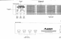
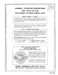
2.1 coturuEc',oil to ADAIfst
The RMB comes with a snake with four male,9-pin D
connectors at each end (labeled 1-4), which is used to connect the
RMB to up to four ADATs. The end of the snake fanned out into
short cablesshould connectto the RMB, and the end with longer
cablesshould connect to the ADATs. If the installation requires
a cable longer than that supplied, use high-quality shielded
cableswired pin-to-pin. Lengths of 100feet or more may be
acceptable,depending upon the quality of the cables and
connectorsused. The ADATs are connectedto the corresponding
connectors on the back of the RMB, with respect to the tracks
eadr ADAT is being used for (see figure 1). These connections
can be made while the power is on.
To connect the RMB to a four-ADAT system:
1. Connect one end of the cable labeled "1" to the Meter Bridge
Out connector of the first ADAT (tracks 1-€), and connect the
other end to the Tracks 1-8 connector on the RMB. Push each
connector firmly into its socket, then tighten both screws;
'Z' to the Meter Bridge
2. Connect one end of the cable labeled
(tracks
9-15), and connect
Out connector of the second ADAT
on the RMB;
connector
Tracks
9-15
the other end to the
"3" to the Meter Bridge
3. Connect one end of the cable labeled
Out connector of the third ADAT (tracks 17-24), and connect
the other end to the Tracks 17-24 connector on the RMB;
4. Connect one end of the cable labeled '(' to the Meter Bridge
Out connector of the fourth ADAT (tracks 25-32), and
connect the other end to the Tracks 2ts32 connector on the
RMB.
Figure 1
f_____-l-_ir-__5
I I r - r l
l
-
4
----------------
Sy c
+
MeterBridge
t
q
t
a
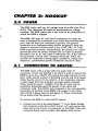
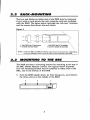
2.2
R,AGK-MOUNTINE
The two end blocks on either end of the RMB may be removed,
if you wish to rack-mount the unit using the rack ears induded
with the RMB. The figure below indicates the rack ears' locations
and the screws that mount the end blocks.
Fizure 2
T
g UseONLYthe 1" hex screws
t to attach the end blocks
, UseONLYthe5/15" phillips
I sc?ewsto attach the rackear!
NOTE: Unlike the BRC, the RMB end blocks will not fit over the rack ears. Depending
on your installation neds, one or the other will be attached to the RMB.
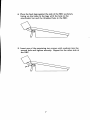
2.3
INOUNJ|/NE JO THE BRC
The RMB includes a mounting bracket for attaching to the top of
the BRC Master Remote Control. The figures below illustrate
how the mounting bracket may be attached to either side of the
BRC, and to the bottom of the RMB.
1. Turn the RMB upside down, its front facing you, and remove
the three screws in the middle of the RMB.
Place the attachment bar on the bottom of the RMB, with its
arms extending towards you. Fasten the attachment bar to
the RMB using the three soews rernoved in step L and the
washers provided.
Match up the two holes in the side of the attachment bar with
the threaded holes in the side of the RMB. Attach the
RMB/bar assemblyto the BRC by inserting one screw and
washer on each side, through the front hole. Tighten these
two screws securelv.
IMPORTANTi MAKE SURE THESE SCREWSARE THE 5/16"
SCREWSINCLUDED WITI{ THE RMB PACKAGE, NOT
THE LONGER SCREWSINCLUDED WTTFI THE BRC AND
INTENDED FOR USE WITH THE ROLL-AROTIND STAND.
NOTE; If your BRC is attachedto a stand, skip to step 5. If your
BRC is table standing, move on to step 4.
4. Place the back legs against the side of the BRC as shown,
lining up the holes in the legs with the hole in the
attachment bar and the threaded hole in the BRC.
Insert one of the remaining two screws with washers into the
second hole and tighten securely. Repeat for the other side of
the BRC.
GHAPIER 3g BASI9
OPER.A7|ON
3.O
POWERIN@-UP
Normally, the RMB does not need to be powered up in any order
with respectto the ADATs and the BRC for it to work properly.
The power switch may be found on the left side of the back of the
RMB.
When the RMB is powered up, a welcome messageis displayed
in the bargraph indicators with the "Alesis" company logo. This
messagedisappearsafter a brief moment. At this point, the RMB
recalls the most recent mode of operation (the Iast mode before
power down). The mode is indicated by the LEDs on the left side
of the front panel, above the control buttons. These buttons are
used to changethe operating mode. The DECAY SPEEDand
PEAK MODE buttons define the possible usesof the RMB.
3.1
DECAYSPEED
The DECAY SPEEDbutton is used to toggle between the two
decay speeds(FAST or SLOW) which the bargraph indicators
will use. The currently selectedDecaySpeedis indicated by the
two LEDs located directly above the DECAY SPEEDbutton. Only
one of the speedsmay be selected at a time. If the Decay Speed is
set to SLOW, pressing the DECAY SPEEDbutton will selectthe
FAST setting. If the Decay Speedis set to FAST, pressing the
DECAY SPEEDbutton will select the SLOW setting.
The RMB will automatically adjust the connectedADATs'
displays to match the currently selectedDecay Speedsetting.
3.2
PEAK ITODE
The PEAK MODE button is used to rycle through the three Peak
Modes: Momentary, Continuous or Off. Only one of the modes
may be selectedat a time. Each time the PEAK MODE button is
pressed,the Peak Mode will advance through these three modes.
The PEAK MODE LEDs, located directly above the PEAK MODE
button, indicate the currently selectedmode.
Here are descriptions of the three Peak Modes:
o Momentary: Each track's peak LED indicator will remain lit
for about two seconds.The MOMENTARY LED will be lit to
indicate this mode has been selected.
.
Continuous: Each track's peak LED indicator will remain lit
continuously, until the PEAK CLEAR button is pressed, or
the PEAK MODE is changed.The CONTINUOUS LED will be
lit to indicate this mode has been selected.
.
Off: No peak indicators will appear on any tracks. Both the
MOMENTARY and CONTINUOUS LEDs will be off to
indicate neither of these modes has been selected.
The RMB will automatically adjust the connected ADATs'
displays to match the currently selectedPeak Mode setting.
3.3
PEAK GLEAN.
The PEAK CLEAR button is used to remove any track peak LED
indicators which remain lit while Continuous Peak Mode is
selected.This button will have no effect if the Peak Mode is set to
Momentary or Off.
The RMB will automatically clear the connectedADATs'
bargraph displays whenever the RMB's PEAK CLEAR button is
pressed.
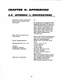
CTIAPTER4s APPENDTCES
4.O
APPENDTX lc SPECIIIGAITONS
Number of Track Indicators:
Front Panel Controls and
Indicators:
Rear Panel Controls and
Connectors:
32
32 drannels of 1S-segmentLED
bargraph indicators; 32 pairs of
LED indicators for track record/
input status; Pushbuttons for
Decay Speed,Peak Mode and
Peak Clea4 LED indicators for
Decay Speed (Fast, Slow) and
Peak Mode (Momentary,
Continuous).
Four 9 pin D-Sub connectors for
ADAT; AC power switch; IECspec AC cord connector.
90-250VAC, 5(H0 FIz,50 W
max.
3-l/2" x79" x3-7/2"
(2 Rack Spaces)
4lbs (1.9kg)
11 bs (a.9kg)
IEC style AC power cord
Owne/s Manual
30' snakeof four 9 pin Dconnectors
BRC mounting bracket, screws/
rack ears and two support legs
AI-1 Digital Interface and
Sample Rate Converter
BRC Master Remote Control
Power Requirements:
Dimensions(HxWxD):
Weight:
Shipping Weight:
Accessories Induded:
Optional Accessories:
10
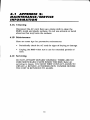
4.1 APPENDIX 2:
TUATNITENANGE/SERYTGE
TNFOR.TUATION
4.1A Cleaning
Disconnect the AC cord, then use a damp cloth to dean the
RMB's metal and plastic surfaces. Do not use solvents or harsh
abrasivesthat mav harm the surfaces.
4.18 Maintenance
Here are some tips for preventive maintenance:
o Periodically check the AC cord for signs of fraying or damage.
o Unplug the RMB when not in use for extended periods of
time.
4.1C Servicing
DO NOT ATTEMPT REPAIRS YOURSELF. THERE ARE NO
USER SERVICEABLE PARTS INSIDE THE RMB. Refer all
servicing to Alesis. YOU MUST FIRST CONTACT ALESIS TO
OBTAIN A RETURN AUTHORIZATION NUMBER BEFORE
THE UNIT IS REruRNED TO ALESIS.
11
,NSIRUGI/,ONS JO f']E USEN,
This equipment has been tested and found to comply with the limits for a dass B
digital device,pursuant to Part 15 of the FCC Rules. Theselimits are designedto
provide reasonableprotection against harmful interference in a residential
installation. This equipment generates,usesand can radiate radio frequency
energy and, if not installed and used inaccordancewith the instructions,may
causeharmful interferenceto radio communications. However, thereis no
guarantee that interference will not occur in a particular installation. If this
equipment does causeharmful interference to radio or television reception,
which can be determined by turning the equipment off and o& the user is
encouraged to try to correct the interference by one or more of the following
measures:
o Reorientor relocatethe receivingantenna.
. Increasethe separationbetweenthe equipment
and receiver.
o Connectthe equipment into an outlet on a circuit
different from that to which the receiver is
connected.
. Consult the dealeror an experiencedradio/TV
technician for help.
This equipment has beenverified to comply with the limits for a classB
computing device,pursuant to FCC Rules. In order to maintain compliance
with FCC regulations,shielded cablesmust be used with this equipment.
Operation with non-approvedequipment or unshielded cablesis likely to result
in interferenceto radio and TV reception. The user is cautionedthat changes
and modifications made to the equipment without the approval of manufacturer
could void the user's authority to operatethis equipment.
ALESIS L'MIIED u'.AN.R.ANJY
("ALESIS"I
ALESIS
CORPORATION
worronlsthisproductfir be freeof defectsin moteriol
ondworkmonshipforoperiodof
I yeorfromtheddteof
originolretoilpurchose.This
worronv is enforceoble
only by theoriqinolretoilpurchoser.
Tobe protectedby thisw'orronty,the-purchoser
mustcompleteond returntheenclosed
worronfycord wifiin l4 doysof purchose.
Duringlhe worronVperiodALESIS
sholl,ot its soleond obsoluteoption,eilherrepoiror
r.eploce
or its
Freeof chorgJony productthotprovesto be defectiveon inspection
by ALESIS
outhorizedservicereoresenlolive.
Toobtoinworron! service,lhe purchosermustfirstcoll or wrifeALESIS
ot theoddress
ond telephonenumberpriniedbelowto obtoino ReturnAufhorizotionNumberond
wherelo returntheunitfor service.
All inquiries
muslbe
instructions
concerninq
occomponied
by o deicriptionof theproblem.,Allouthorizedrehrrnsmustbe senlto ALESIS
or on outhorizedALESIS
repoirfocilitypostogeprepoid,insuredond properlypockoged.
Proofof purchosemuslbe presenbdin theformof o bill of sole,concelledcheckor some
the right
reserves
otherpoiitiveproof thottheproductis withintheworrontyperiod.ALESIS
to updoteony unil relurnedfor repoir.ALESIS
reserves
the rightto chongeor improve
designof the produclot ony iimewithoutprior notice.
ThisworronVdoesnot covercloimsbr domoqedueio obuse,neolect,olterotionor
personnel,
repoirby unouthorized
onJis limitedto foiiure!oriiingduringnormol
oitempted
in moteriolor workmonship
in theproduct.
usethotoredueto defects
ANY IMPLIED
WARMNTIES,INCLUDING
IMPLIED
WARRANTIES
OF MERCHANTABILIW
FORA PARTICUIAR
PURPOSE,
ARELIMITED
IN DURATIONTO THELENGTH
AND FITNESS
WARRANTY.
Somestotesdo not ollow limitotionson how long on implied
OF THISLIMITED
worrontylosts,so theobovelimitotionmoy nol opplyto you.
FORINCIDENTAL,
CONSEOUENTIAL
OR OTHER
IN NO EVENTWILLALESIS
BELIABLE
WARRANW.
FROMTHEBREACHOF ANY EXPRESS
OR IMPLIED
DAIv1AGES
RESULTING
DAMAGEBASEDON
INCLUDING,
AMONG OTHERTHINGS,DAMAGETO PROPERry
AND,TOTHEEXIENT
INCONVENIENCE
ORON LOSSOF USEOF THEPRODUCT,
INJURY.
PERMITTED
BYLAW DAMAGESFORPERSONAL
Someslotesdo not ollowthe
domoges,so theobo"e limilofionor
exclusionor limitotionof incidentolor consequentiol
exclusionmoy notopply to you.
Thisworrontygirbi you ipecificlegolrights,ond you moy olsohoveotherrightswhich
vory trom sloteto stote.
fhis worrontyonly oppliesto productssoldond usedin the UnitedStotesof Americo.For
worrontyinformqtioniri oll othei counlriespleosereforto your locoldistributrcr.
r#Hlo*"*
3630
90016
Los
Angeles,
Colifornio
I -(800)-5-ALESIS
Your worronty will be in effect
ond you will receive worronty informotion
ONLY IF YOU SENDIN YOUR WARRANTYCARD
ForCustomer
ServiceIn Mexicocoll:95-(800)-5-ALESIS
-tcG|Er
Alesisoorporation
3630HoldrcgeA\,enue
LosAngeles
CA 90016
E
O 1993
Alesis
Corporation
Sp€cificalions
Subject
ToChanoe
Without
NoticePrinted
InUSAA2997.51n072