1
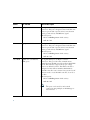
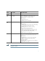
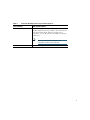
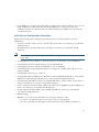
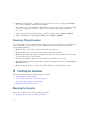
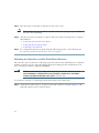
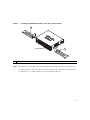
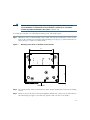
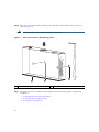
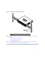
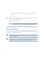
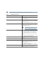
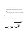
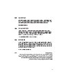
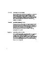
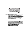
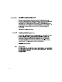
GETTING STARTED GUIDE
Cisco 2500 Series Wireless Controller
May 2011
Revised June 2, 2011
1
About This Guide
2
Unpacking and Preparing the Controller for Operation
3
Installing the Controller
4
Running the Bootup Script and Power-On Self Test
5
Logging into the Controller
6
Connecting to the Network
7
What’s New in Cisco Product Documentation
8
Translated Safety Warnings
1 About This Guide
This guide is designed to help you install and minimally configure your Cisco 2504 Wireless Controller
(2504 controller), which is part of the Cisco 2500 Series Wireless Controllers.
FCC Safety Compliance Statement
This equipment has been tested and found to comply with the limits for a Class B digital device,
pursuant to Part 15 of the FCC Rules. These limits are designed to provide reasonable protection
against harmful interference in a residential installation. This equipment generates, uses, and can
radiate radio frequency energy and, if not installed and used in accordance with the instructions, may
cause harmful interference to radio communications. However, there is no guarantee that interference
will not occur in a particular installation. If this equipment does cause harmful interference to radio
or television reception, which can be determined by turning the equipment off and on.
Try to correct the interference by one or more of the following measures:
• Reorient or relocate the receiving antenna.
• Increase the separation between the equipment and receiver.
• Connect the equipment to an outlet on a circuit different from that to which the receiver is
connected.
• Consult the dealer or an experienced radio/TV technician for help. (cfr reference 15.105)
Safety Information
Safety warnings appear throughout this guide in procedures that may harm you if performed
incorrectly. A warning symbol precedes each warning statement. The warnings below are general
warnings that are applicable to the entire guide. Translated versions of the safety warnings in this guide
are provided in the “Translated Safety Warnings” section on page 39.
Warning
2
This warning symbol means danger. You are in a situation that could cause bodily injury.
Before you work on any equipment, be aware of the hazards involved with electrical
circuitry and be familiar with standard practices for preventing accidents. Use the
statement number provided at the end of each warning to locate its translation in the
translated safety warnings that accompanied this device. Statement 1071
SAVE THESE INSTRUCTIONS
Warning
There is the danger of explosion if the battery is replaced incorrectly. Replace the battery
only with the same or equivalent type recommended by the manufacturer. Dispose of
used batteries according to the manufacturer’s instructions. Statement 1015
Warning
This equipment must be grounded. Never defeat the ground conductor or operate the
equipment in the absence of a suitably installed ground conductor. Contact the
appropriate electrical inspection authority or an electrician if you are uncertain that
suitable grounding is available. Statement 1024
Warning
Ultimate disposal of this product should be handled according to all national laws and
regulations. Statement 1040
Safety Considerations
• Verify that the ambient temperature remains between 32 to 104° F (0 to 40° C), taking into
account the elevated temperatures when installed in a rack or enclosed space.
• When multiple 2504 controllers are mounted in an equipment rack, be sure that the power source
is sufficiently rated to safely run all the equipment in the rack (input: 100 to 240 VAC, 50–60 Hz,
output: 80 W per controller).
• Verify the integrity of the electrical ground before installing the controller.
Introduction to the Controller
The 2504 controller works in conjunction with Cisco lightweight access points and the Cisco Wireless
Control System (WCS) to provide system-wide wireless LAN functions. As a component of the Cisco
Unified Wireless Network (CUWN), the 2504 controller provides real-time communication between
wireless access points and other devices to deliver centralized security policies, guest access, Wireless
Intrusion Prevention System (WIPS), context-aware (location), award-winning RF management,
quality of services for mobility services such as voice and video, and OEAP support for the Teleworker
solution.
The 2504 controllers supports up to 50 lightweight access points in increments of 5 access points with
a minimum of 5 access points, making it a cost-effective solution for retail, enterprise branches, and
small and medium-sized businesses. The 2504 controller comes with four 4 Gigabit Ethernet ports.
3
Note
Direct connection of access points to Cisco 2500 Series Wireless Controllers are not currently
supported.
The 2504 controller offers robust coverage with 802.11 a/b/g and delivers unprecedented reliability
using 802.11n with Cisco Next-Generation Wireless Solutions and Cisco Enterprise Wireless Mesh.
To best use this guide, you should have already designed the wireless topology of your network and
have a working knowledge of how controllers function in a wireless LAN network.
Figure 1 shows a 2504 controller network topology and network connections, showing the medium
dependent interface (MDI) Ethernet cables required. The controller has an auto MDI feature, so you
can use straight-through or crossover cables.
Figure 1
Typical Controller Topology and Network Connections
Console emulator
for initial boot-up
Cisco WCS software,
web user interface
Null modem serial
cable (DB-9 -> RJ-45)
to console connection
10/100/1000BASE-T
MDI cable
Network
Distribution
system
connection
LAN link for
management software
connections
WAN or LAN
connection to
main office
10/100/1000BASE-T
MDI cables
282297
Access
point
connections
Cisco Access Points
4
Figure 2 shows the front panel and location of the ports and light-emitting diodes (LEDs) for the 2504
controller. Table 1 describes the components of the front panel.
Note
It is expected that there will be small variations in LED color intensity and hue from unit to
unit. This is within the normal range of the LED manufacturer’s specifications and is not a
defect.
Figure 2
Front Panel and LEDs
Model 2504
RESET
CONSOLE
CONSOLE
1
2
1
2
3
4
3-4 POE
PWR
SYS
ALM
282249
CISCO 2500 Series WIRELESS CONTROLLER
RESET
PWR ALM
SYS
Table 1
WLC2504 Front Panel Component Descriptions
Callout
Port and LEDs
State and Description
CONSOLE
CPU console port
The CPU console port is an RS-232 port that supports
a RJ-45 connector. At boot-up the controller configures
the RS-232 port as a console port with default settings
of 9600, N, 8, 1. The boot-loader supports baud rates
of 1200, 2400, 4800, 9600, 19200, 38400, 57600, and
115200. A default baud-rate recovery mechanism is not
available; however the bootloader ensures that the
stored baud rate setting matches one of the allowed
values before setting the baud rate. If a nonstandard
value is detected the baud rate will default to 9600.
5
Callout
Port and LEDs
State and Description
1
GigE port and LED
The Gigabit Ethernet port is an RJ-45 connector
form-factor. This port is designed so that 1500 VAC rms
isolation (per the 802.3 specification) is met between
chassis ground and any 48V/Ethernet signal.
LED description:
• Green or Blinking Green—Link activity
• Off—No link
2
GigE port and LED
The Gigabit Ethernet port is an RJ-45 connector
form-factor. This port is designed so that 1500 VAC rms
isolation (per the 802.3 specification) is met between
chassis ground and any 48V/Ethernet signal.
LED description:
• Green or Blinking Green—Link activity
• Off—No link
3 & 4 POE
GigE Power-over-Ethernet
(POE) ports
The Gigabit POE ports are RJ-45 connector
form-factor. They provide a I2C communications
channel between the PSE controller and host CPU TWSI
bus #1. This interface supports the proper voltage
isolation as defined by 802.3. The POE controller is
configured to I2C address 0x40/41 (0100 000r/w).
The POE controller reset is driven from system reset. If
software needs to reset the POE controller, it can do so
over I2C.
LED description:
• Green or Blinking Green—Link activity
• Off—No link
Note
6
The ports can be used for infra-switch
connection using multiple an AP-Manager or
data interface.
Callout
Port and LEDs
State and Description
RESET
Reset button
Pushing the Reset button reboots the system.
PWR
Power LED
The power LED light is on when all the power
conversion circuits are running normally.
LED description:
• Green—Power is on
• Off—No power to the system
SYS
System LED
The system LED determines if the system is powered up.
LED description:
• Blinking Amber—Boot-loader is active and waiting
for user input from the system console.
• Blinking Green—Boot-loader or booting.
• Green—Normal System Operation.
• Amber—System failed the bootup process or an
error caused the system to halt. A status or error
message is posted on the console screen.
• Off—System not receiving power.
ALM
Alarm LED
The alarm LED determines a status or error occurred.
The status or error is posted on the console screen.
LED description:
• Blinking Green—Controller image upgrading.
• Amber—Controller status activity, such as
firmware upgrade.
• Blinking Amber—Controller error. For example, a
temperature error exists.
Caution
Do not connect a Power over Ethernet (PoE) cable to the console port. Doing so will
damage the controller.
7
Note
Wait at least 20 seconds before reconnecting an access point to the controller. Otherwise, the
controller may fail to detect the device.
Note
From the AireOS V 7.3 onward, APs can be connected directly to all ports. However the PoE
powering to the APs is not fully supported. Power Injectors or external power source for APs
is needed.
Note
Precautions for the direct AP connection: Do not configure interfaces on the physical
ports, if AP is connected to the port. If an interface is configured on the port where AP is
connected, the behavior is undefined. If the physical ports are configured, remove it and
reload the controller.
Figure 3 shows the back panel and identifies its components. Table 2 describes the back panel
components.
Controller Back Panel and Components
282250
Figure 3
POWER 48VDC
8
Cable Lock
Slot
Table 2
Controller Back Panel and Component Descriptions
Ports and Slots
State and Description
POWER 48VDC
The 48 V input power is provided via an external
AC/DC adapter. Power is provided to the system board
from the 48 VDC input. There is enough power
available to power the system board plus two 802.3af
PoE devices.
Note
Cable Lock slot
The Cisco 2106 power adapter is not
compatible with a 2504 controller.
Security locking slot.
9
2 Unpacking and Preparing the Controller for Operation
Follow these steps to unpack the 2504 controller and prepare it for operation:
Step 1
Open the shipping container and carefully remove the contents.
Step 2
Return all packing materials to the shipping container and save it.
Step 3
Ensure that all items listed in the “Package Contents” section are included in the shipment.
Check each item for damage. If any item is damaged or missing, notify your authorized Cisco
sales representative.
Package Contents
Each 2504 controller package contains the following items:
• One Cisco 2504 Wireless Controller.
• One Power supply and power cord (power cord option configurable).
• Cisco 2504 Wireless Controller software pre-loaded on the controller (software option
configurable).
• Optional licenses will be pre-installed on controller at factory, if selected.
• Two Number 6 Phillips pan-head screws for mounting the controller on a desk, shelf, or wall.
• Two wall anchors.
• Strain relief clip and screw.
• Optional hardware will be included, if selected.
Required Tools and Information
You will need the following tools and information before you can install the controller:
• Wireless controller hardware
– Controller with factory-supplied power cord and mounting hardware
– Network, operating system service network, and access point cables as required
• Command-line interface (CLI) console
– VT-100 terminal emulator on CLI console (PC, laptop, or palmtop)
– Null modem serial cable to connect CLI console and controller
10
• Local TFTP server (required for downloading operating system software updates). Cisco uses an
integral TFTP server. This means that third-party TFTP servers cannot run on the same
workstation as the Cisco WCS because Cisco WCS and third-party TFTP servers use the same
communication port.
Initial System Configuration Information
Obtain the following initial configuration parameters from your wireless LAN or network
administrator:
• A system (controller name), such as controller. The system name can contain up to 32 printable
ASCII characters.
• An administrative username and password, which can contain up to 24 printable ASCII
characters.
Note
You must enter a username and password and the configured username and password cannot
be the same.
• A management interface (DS Port or network interface port) IP address, such as 10.40.0.4.
• A management interface netmask address, such as 255.255.255.0.
• A management interface default router IP address, such as 10.40.0.5.
• A VLAN identifier if the management interface is assigned to a VLAN, such as 40 or 0 for an
untagged VLAN.
• A management interface port, such as 1.
• A management interface DHCP server IP address, such as 10.40.0.6 (the IP address of the default
DHCP server that will supply IP addresses to clients and the management interface.
• A virtual gateway IP address (a fictitious, unassigned IP address, such as 1.1.1.1, used by all Cisco
wireless controller Layer 3 security and mobility managers).
• A Cisco wireless controller mobility or RF group name, such as rfgrp40 if required. An RF group
name can contain up to 19 printable ASCII characters.
• An 802.11 network name (SSID), such as wlan1. An SSID can contain up to 32 printable,
case-sensitive ASCII characters.
• DHCP bridging
• Whether or not to allow static IP addresses from clients, either Yes or No.
– Yes is more convenient, but has lower security (session can be hijacked).
– No is less convenient, but has higher security and works well for Windows XP devices.
11
• RADIUS server IP address, communications port, and secret if you are configuring a RADIUS
server, such as 10.40.0.3, 1812, and mysecretcode.
• The country code for this installation. Enter help to see a list or refer to the Cisco Wireless LAN
Controller Configuration Guide for country code information. This guide is available at
cisco.com.
• Status of the 802.11a, 802.11b, 802.11g, or 802.11n networks, either enabled or disabled.
• Status of Radio Resource Management (RRM), either enabled or disabled.
Choosing a Physical Location
You can install the controller almost anywhere, but it is more secure and reliable if you install it in a
secure equipment room or wiring closet. For maximum reliability, mount the controller while
following these guidelines:
• Make sure you can reach the controller and all cables attached to it.
• Make sure that water or excessive moisture cannot get into the controller.
• Make sure that airflow through the controller is not obstructed. Leave at least 4 in. (10 cm) clear
on both sides and rear of the controller.
• Verify that the ambient temperature remains between 32 to 104° F (0 to 40° C).
• Make sure that the controller is within 328 ft. (100 m) of equipment connected to the 10/100/1000
Mb/s Ethernet ports.
• Make sure that the power cord can reach a 100 to 240 VAC grounded electrical outlet.
3 Installing the Controller
This section includes the following installation procedures:
• Mounting the Controller, page 12
• Connecting the Controller Console Port, page 22
• Securing the Power Adapter Cable, page 22
• Installing a Security Lock, page 24
Mounting the Controller
This section includes the following mounting procedures:
• Mounting the Controller on a Desktop or Shelf
12
• Mounting the Controller on a Wall (Rack-Mount Brackets)
• Mounting the Controller on a Wall (Mounting Screws)
• Mounting the Controller in a Rack
Mounting the Controller on a Desktop or Shelf
Before mounting the controller on a desktop or shelf, install the rubber feet located in accessory kit
shipped with the controller.
To install the rubber feet to the controller, follow these steps:
Step 1
Locate the adhesive strip with the rubber feet in the mounting-kit envelope.
Step 2
Remove the four rubber feet from the adhesive strip and attach the feet to the recessed areas
on the bottom of the unit as shown in Figure 4.
Figure 4
We strongly recommend that you attach the rubber feet. Doing so helps prevent airflow
restriction and overheating.
Installing the Rubber Feet on the Bottom of the Controller
282084
Note
13
Step 3
Place the switch on the table or shelf near an AC power source.
Note
Step 4
Allow 3 inches of space around the controller ventilation openings to prevent airflow
restriction and overheating.
After the controller is mounted on a shelf or desk, perform the following tasks to complete
the installation:
• Connecting the Controller Console Port
• Securing the Power Adapter Cable
• Connecting to the Network
Step 5
For configuration instructions about using the CLI setup program, see the “Running the
Bootup Script and Power-On Self Test” section on page 24.
Mounting the Controller on a Wall (Rack-Mount Brackets)
The controller can be mounted on a wall using an optional rack-mount bracket kit that is not included
with the controller. You can order a kit with 19-inch rack mounting brackets and hardware from
Cisco. The kit part number is AIR-CT2504-RMNT.
Warning
Read the wall-mounting carefully before beginning installation. Failure to use the
correct hardware or to follow the correct procedures could result in a hazardous
situation to people and damage to the system. Statement 378
To mount the controller on a wall using rack-mount brackets, follow these steps:
Step 1
14
Attach the 19-inch brackets to each side of the 2504 controller as shown in Figure 5 with
#10-32 flat head screws provided in the kit.
Figure 5
Installing the Rack-Mount Brackets to the Sides of the Controller
282083
1
BASE MOUNT
1
1
#10-32 flat head screws (mounting screws for each side of the controller)
Step 2
Mount the 2504 controller on the wall with the front panel facing down, as shown Figure 6.
For the best support of the controller and cables, make sure the controller is attached securely
to wall studs or to a firmly attached plywood mounting backboard.
15
Mounting the Controller on the Wall
1
1
Front panel (facing down)
2
#10-32 flat head screws
Step 3
2
3
3
282085
Figure 6
Wall mounting screws
After the controller is mounted on the wall, perform the following tasks to complete the
installation:
• Connecting the Controller Console Port
• Securing the Power Adapter Cable
• Connecting to the Network
Step 4
For configuration instructions about using the CLI setup program, see the “Running the
Bootup Script and Power-On Self Test” section on page 24.
Mounting the Controller on a Wall (Mounting Screws)
When mounting the 2504 controller on a wall using mounting screws, always mount the controller
with the front panel facing down.
16
Warning
Read the wall-mounting carefully before beginning installation. Failure to use the
correct hardware or to follow the correct procedures could result in a hazardous
situation to people and damage to the system. Statement 378
To mount the controller on a wall using mounting screws, follow these steps:
Step 1
Figure 7
Mark the location of the mounting screws on the wall. Use the mount hole locations on the
back of the controller for placement of the mounting screws (Figure 7). (The mount holes are
shown in Figure 7 with a cross-hatch mark.)
Mounting Screw Holes on the Back of the Controller
FRONT PANEL
282087
3.9
5.5
Step 2
Use a 0.107-inch (2.7mm) or #32 drill bit to drill a 3/4 inch (19mm) hole for the two mounting
screws.
Step 3
Insert two screws into the screw holes and tighten until the top of the screws are 1/8 inch from
the wall (leaving enough room for the back panel to slide onto the screws firmly).
17
Place the controller onto the mounting screws and slide it down until it lock into place, as
shown in Figure 8.
Note
Figure 8
The front panel of the controller should be facing down.
Place the Controller on the Mounting Screws
2
1
1
2
Front panel (facing down)
Step 5
2
Mounting screws
After the controller is mounted ion the wall, perform the following tasks to complete the
installation:
• Connecting the Controller Console Port
• Securing the Power Adapter Cable
• Connecting to the Network
18
282085
Step 4
Step 6
For configuration instructions about using the CLI setup program, see the “Running the
Bootup Script and Power-On Self Test” section on page 24.
Mounting the Controller in a Rack
To mount the 2504 controller in a 19-inch equipment rack, you can order an optional Optional Rack
Mount kit (AIR-CT2504-RMNT).
Warning
To prevent bodily injury when mounting or servicing this unit in a rack, you must take
special precautions to ensure that the system remains stable. The following guidelines
are provided to ensure your safety:
• This unit should be mounted at the bottom of the rack if it is the only unit in the rack.
• When mounting this unit in a partially filled rack, load the rack from the bottom to the
top with the heaviest component at the bottom of the rack.
• If the rack is provided with stabilizing devices, install the stabilizers before mounting
or servicing the unit in the rack. Statement 1006
To install the controller in a rack, follow these steps.
Step 1
Attach the 19-inch brackets to each side of the controller as shown in Figure 9 with #10-32
flat head screws provided in the kit.
19
Figure 9
Attaching the 19-Inch Brackets to the Side of the Controller.
282082
1
RACK MOUNT
1
1
#10-32 flat head screws (mounting screws for each side of the controller)
Step 2
20
After the brackets are attached to the sides of the controller, insert the controller into the
19-inch rack. Use either the 10-32 pan-head screws or the 12-24 slotted head screws to secure
the controller in the rack, as shown in Figure 10.
Figure 10
Mounting the Controller in a 19-Inch Rack
282086
1
1
Step 3
#10-32 pan-head screws or #12-24 slotted head screws
After the controller is mounted in the rack, perform the following tasks to complete the
installation:
• Connecting the Controller Console Port
• Securing the Power Adapter Cable
• Connecting to the Network
Step 4
For configuration instructions about using the CLI setup program, see the “Running the
Bootup Script and Power-On Self Test” section on page 24.
21
Connecting the Controller Console Port
Caution
Do not connect a Power over Ethernet (PoE) cable to the console port. Doing so will
damage the controller.
Before you can configure the 2504 controller for basic operations, you need to connect it to a PC that
uses a VT-100 terminal emulator (such as HyperTerminal, ProComm, Minicom, or Tip). To connect
the PC to the controller console port, follow these steps:
Step 1
Plug the RJ-45 connector on a null-modem serial cable into the controller console port and
the other end of the cable into the serial port of the PC.
Step 2
Start the PC terminal emulation program.
Step 3
Configure the terminal emulation program for the following parameters:
• 9600 baud
• 8 data bits
• No flow control
• 1 stop bit
• No parity
Securing the Power Adapter Cable
To secure the power adapter cable to the 2504 controller, use the plastic relief clip shipped with the
cable. The clip relieves the cable in the event it falls and prevents the connector from being sheared off
at the plug pins.
Caution
Note
If the relief clip is not installed, the power connector can be damaged if the power cable
is pulled or if the power adapter falls.
The Cisco 2106 power adapter is not compatible with a 2504 controller.
To secure the power adapter cable and plug, follow these steps:
22
Step 1
Wrap the power adapter cable through the plastic security clip as shown in Figure 11.
Plastic Relief Clip
281917
Figure 11
Fasten the security clip with a screw to the existing hole on the back panel on the 2504
controller (see Figure 12).
Figure 12
Securing the Power Adapter Cable
281918
Step 2
1
3
2
23
Security clip secured with screw
1
2
3
Power plugged into the POWER 48VDC
port.
AC/DC power adapter cable
Installing a Security Lock
The controller has a security slot on the back panel. You can install an optional customer-supplied
cable lock, such as the type that is used to secure a laptop computer, to secure the controller. Refer to
Figure 3 for the location of the security lock.
4 Running the Bootup Script and Power-On Self Test
When you plug the controller into an AC power source, the bootup script initializes the system, verifies
the hardware configuration, loads its microcode into memory, verifies its operating system software
load, and initializes itself with its stored configurations. Before performing this test, you should have
connected your PC to the CLI console on the controller as described in the “Connecting the Controller
Console Port” section on page 22.
To run the bootup script and conduct the power-on self test (POST), follow these steps:
Step 1
Plug the external power supply into the power jack on the back of the controller.
Step 2
Plug a country-specific power cord into the external power supply, then plug the other end
into a grounded 100 to 240 VAC, 50–60 Hz electrical outlet.
24
Note
If you wish to run a previous release of the controller code, press Esc when the boot
loader prompt appears. The Bootloader Options menu appears.
Note
When the controller receives power, the green front panel Power LED lights. If the
Power LED does not light, make sure that the electrical outlet is supplying power and
that the power connections to the controller are correct.
Step 3
Observe the bootup using the CLI screen.
The bootup script displays operating system software initialization (code download and POST
verification) and basic configuration as shown in the following bootup display example:
CISCO SYSTEMS
WLCNG Boot Loader Version 1.0.15 (Built on Nov 23 2010 at 07:51:36 by cisco)
Board Revision 0.0 (SN: PSJ143302MT, Type: AIR-CT2504-K9) (P)
Verifying boot loader integrity... OK.
OCTEON CN5230C-SCP pass 2.0, Core clock: 750 MHz, DDR clock: 330 MHz (660 Mhz data
rate)
CPU Cores: 4
DRAM: 1024 MB
Flash: 32 MB
Clearing DRAM........ done
Network: octeth0', octeth1, octeth2, octeth3
' - Active interface
E - Environment MAC address override
CF Bus 0 (IDE): OK
IDE device 0:
- Model: 1GB CompactFlash Card Firm: CF B612J Ser#: C181101244A1Yb3A5QNU
- Type: Hard Disk
- Capacity: 977.4 MB = 0.9 GB (2001888 x 512)
Press <ESC> now to access the Boot Menu...
Continue booting the controller or press Esc to access the following menu:
============================================================
Boot Loader Menu
============================================================
1. Run primary image (7.0.114.76) - Active
2. Run backup image (7.0.114.75)
3. Change active boot image
4. Clear configuration
5. Format FLASH Drive
6. Manually update images
-----------------------------------------------------------Enter selection:
If you did not press Esc, the boot process continues and takes two to three
minutes. Do not reboot the controller until the user login prompt appears.
Loading primary image (7.0.114.76)
100%
31427987 bytes read
Launching images...
init started: BusyBox v1.6.0 (2010-05-13 17:50:10 EDT) multi-call binary
starting pid 672, tty '': '/etc/init.d/rcS'
type = block
dump-device = 254:4
disrupt
level = header
25
compress = none
ifconfig: SIOCGIFFLAGS: No such device
Detecting Hardware ...
Installing ether-pow driver - 0x6008
starting pid 805, tty '/dev/ttyS0': '/usr/bin/gettyOrMwar'
Cryptographic library self-test....passed!
XML config selected
Validating XML configuration
octeon_device_init: found 1 DPs
/dev/fpga: No such device or address
readCPUConfigData: cardid 0x6060001
Cisco is a trademark of Cisco Systems, Inc.
Software Copyright Cisco Systems, Inc. All rights reserved.
Cisco AireOS Version 7.0.114.76
Firmware Version PIC 14.0
Initializing OS Services: ok
Initializing Serial Services: ok
Initializing Network Services: ok
Initializing Licensing Services: ok
Starting ARP Services: ok
Starting Trap Manager: ok
Starting Network Interface Management Services: ok
Starting System Services: ok
Starting Fastpath Hardware Acceleration: ok
Starting Fastpath Console redirect : ok
Starting Fastpath DP Heartbeat : ok
Fastpath CPU00: Starting Fastpath Application. SDK-1.8.0, build 269. Flags-[DUTY
CYCLE] : ok
Fastpath CPU00: Initializing last packet received queue. Num of cores(2)
Fastpath CPU00: Init MBUF size: 1856, Subsequent MBUF size: 2040
Fastpath CPU00: Core 0 Initialization: ok
Fastpath CPU00: Initializing Timer...
Fastpath CPU01: Core 1 Initialization: ok
Fastpath CPU00: Initializing Timer...done.
Starting Switching Services: ok
Starting QoS Services: ok
Starting Policy Manager: ok
Starting Data Transport Link Layer: ok
Starting Access Control List Services: ok
Starting System Interfaces: ok
Starting Client Troubleshooting Service: ok
Starting Management Frame Protection: ok
Starting Certificate Database: ok
Starting VPN Services: ok
Starting Licensing Services: ok
Starting LWAPP: ok
Starting CAPWAP: ok
Starting LOCP: ok
Starting Security Services: ok
26
Starting Policy Manager: ok
Starting Authentication Engine: ok
Starting Mobility Management: ok
Starting Virtual AP Services: ok
Starting AireWave Director: ok
Starting Network Time Services: ok
Starting Cisco Discovery Protocol: ok
Starting Broadcast Services: ok
Starting Logging Services: ok
Starting DHCP Server: ok
Starting IDS Signature Manager: ok
Starting RFID Tag Tracking: ok
Starting Power Supply and Fan Status Monitoring Service: ok
Starting Mesh Services: ok
Starting TSM: ok
Starting CIDS Services: ok
Starting Ethernet-over-IP: ok
Starting DTLS server: enabled in CAPWAP
Starting CleanAir: ok
Starting WIPS: ok
Starting SSHPM LSC PROV LIST: ok
Starting RRC Services: ok
Starting FMC HS: ok
Starting Management Services:
Web Server: ok
CLI: ok
Secure Web: Web Authentication Certificate not found (error). If you cannot
access management interface via HTTPS please reconfigure Virtual Interface.
License Agent: ok
(Cisco Controller)>
Step 4
If desired, press Esc key to interrupt the boot process and access the Boot menu.
27
Step 5
Continue booting the controller or press Esc to access the following menu:
1. Run primary image (7.0.114.76) - Active
2. Run backup image (7.0.114.75)
3. Change active boot image
4. Clear configuration
5. Format FLASH Drive
6. Manually update images
-----------------------------------------------------------Enter selection:
If you did not press Esc, the boot process continues and takes two to three minutes. Do not
reboot the controller until the user login prompt appears.
Loading primary image (7.0.114.76)
100%
31427987 bytes read
Launching images...
init started: BusyBox v1.6.0 (2010-05-13 17:50:10 EDT) multi-call binary
starting pid 672, tty '': '/etc/init.d/rcS'
type = block
dump-device = 254:4
disrupt
level = header
compress = none
ifconfig: SIOCGIFFLAGS: No such device
Detecting Hardware ...
Installing ether-pow driver - 0x6008
starting pid 805, tty '/dev/ttyS0': '/usr/bin/gettyOrMwar'
Cryptographic library self-test....passed!
XML config selected
Validating XML configuration
octeon_device_init: found 1 DPs
/dev/fpga: No such device or address
readCPUConfigData: cardid 0x6060001
Cisco is a trademark of Cisco Systems, Inc.
Software Copyright Cisco Systems, Inc. All rights reserved.
Cisco AireOS Version 7.0.114.76
Firmware Version PIC 14.0
Initializing OS Services: ok
Initializing Serial Services: ok
Initializing Network Services: ok
Initializing Licensing Services: ok
Starting ARP Services: ok
Starting Trap Manager: ok
Starting Network Interface Management Services: ok
Starting System Services: ok
Starting Fastpath Hardware Acceleration: ok
Starting Fastpath Console redirect : ok
28
Starting Fastpath DP Heartbeat : ok
Fastpath CPU00: Starting Fastpath Application. SDK-1.8.0, build 269. Flags-[DUTY
CYCLE] : ok
Fastpath CPU00: Initializing last packet received queue. Num of cores(2)
Fastpath CPU00: Init MBUF size: 1856, Subsequent MBUF size: 2040
Fastpath CPU00: Core 0 Initialization: ok
Fastpath CPU00: Initializing Timer...
Fastpath CPU01: Core 1 Initialization: ok
Fastpath CPU00: Initializing Timer...done.
Starting Switching Services: ok
Starting QoS Services: ok
Starting Policy Manager: ok
Starting Data Transport Link Layer: ok
Starting Access Control List Services: ok
Starting System Interfaces: ok
Starting Client Troubleshooting Service: ok
Starting Management Frame Protection: ok
Starting Certificate Database: ok
Starting VPN Services: ok
Starting Licensing Services: ok
Starting LWAPP: ok
Starting CAPWAP: ok
Starting LOCP: ok
Starting Security Services: ok
Starting Policy Manager: ok
Starting Authentication Engine: ok
Starting Mobility Management: ok
Starting Virtual AP Services: ok
Starting AireWave Director: ok
Starting Network Time Services: ok
Starting Cisco Discovery Protocol: ok
Starting Broadcast Services: ok
Starting Logging Services: ok
Starting DHCP Server: ok
Starting IDS Signature Manager: ok
Starting RFID Tag Tracking: ok
Starting Power Supply and Fan Status Monitoring Service: ok
Starting Mesh Services: ok
Starting TSM: ok
Starting CIDS Services: ok
Starting Ethernet-over-IP: ok
Starting DTLS server: enabled in CAPWAP
Starting CleanAir: ok
Starting WIPS: ok
Starting SSHPM LSC PROV LIST: ok
Starting RRC Services: ok
Starting FMC HS: ok
Starting Management Services:
Web Server: ok
29
CLI: ok
Secure Web: Web Authentication Certificate not found (error). If you cannot
access management interface via HTTPS please reconfigure Virtual Interface.
License Agent: ok
(Cisco Controller)>
Step 6
If the controller passes the POST, the bootup script runs the Startup Wizard, which prompts
you for basic configuration information.
Welcome to the Cisco Wizard Configuration Tool
Use the '-' character to backup
System Name [Cisco_d9:16:24]:
Note
The startup wizard runs the first time that you power on the controller. The second
time you power it on, the controller prompts you for a login ID and password.
Using the Startup Wizard
Before you can use the startup wizard, you must obtain the information discussed in the “Required
Tools and Information” section on page 10. Table 3 contains startup wizard information you can use
to configure your controller for basic operation.
Note
The available options appear in brackets after each configuration parameter. The default value
appears in all uppercase letters.
Note
If you enter an incorrect response, the controller provides you with an appropriate error
message such as invalid response, and returns to the wizard prompt.
30
Note
Table 3
Press the hyphen key if you need to return to the previous command line.
Startup Wizard Information
Wizard Setting
Action
System Name
Enter the system name, which is the name you
want to assign to the controller. You can enter up
to 31 ASCII characters.
Administrative user name
Enter the administrative user name to be assigned
to this controller. You can enter up to 24 ASCII
characters for each.
The default administrative username is admin.
Administrative password
Enter the administrative password to be assigned
to this controller. You can enter from 3 to 24
ASCII characters for each.
Note
Management Interface IP Address
There is no default administrative
password, you must enter a password.
Enter the IP address of the management interface.
The management interface is the default interface
for in-band management of the controller and
connectivity to enterprise services such as AAA
servers.
You can access the controller GUI interface using
the management interface IP address.
Management Interface Netmask
Enter the IP address of the management interface
netmask.
Management Interface Default Router
Enter the IP address of the default router.
Management Interface VLAN Identifier
Enter the VLAN identifier of the management
interface (a valid VLAN identifier or 0 for an
untagged VLAN).
The VLAN identifier should be set to match the
switch interface configuration.
Management Interface Port Num [1 to 4]
Enter the port number of the access point
manager interface. Ports values are 1 to 4.
31
Table 3
Startup Wizard Information (continued)
Wizard Setting
Action
Management Interface DHCP Server IP Address
Enter the management interface DHCP server IP
address.
Virtual Gateway IP Address
Enter the IP address of the controller virtual
interface. You should enter a fictitious,
unassigned IP address, such as 1.1.1.1.
The virtual interface is used to support mobility
management, DHCP relay, and embedded Layer
3 security such as guest web authentication and
VPN termination. All controllers within a
mobility group must be configured with the same
virtual interface IP address.
Mobility/RF Group Name
If desired, enter the name of the mobility
group/RF group to which you want the controller
to belong.
Although the name that you enter here is assigned
to both the mobility group and the RF group,
these groups are not identical. Both groups define
clusters of controllers, but they have different
purposes. All of the controllers in an RF group
are usually also in the same mobility group and
vice versa. However, a mobility group facilitates
scalable, system-wide mobility and controller
redundancy while an RF group facilitates
scalable, system-wide dynamic RF management.
Network Name (SSID)
Enter the network name, or service set identifier
(SSID). This is the default SSID that the access
points use when they join a controller.
Configure DHCP Bridging Mode
Enter yes to configure DHCP Bridging Mode.
Values are yes or no. The following message
appears:
Warning! The default WLAN security policy
requires a RADIUS server. Please see
documentation for more details.
32
Table 3
Startup Wizard Information (continued)
Wizard Setting
Action
Allow Static IP Addresses
Enter YES to allow clients to assign their own IP
address or no to make clients request an IP
address from a DHCP server. Values are YES or
no. The default setting is YES.
Configure a RADIUS Server Now?
If you select YES, you are prompted to enter the
following:
• RADIUS server IP address
• RADIUS server port (default port is 1812)
• RADIUS server secret
If you select no, the following message appears:
Warning! The default WLAN security policy
requires a RADIUS server. Please see
documentation for more details.
Enter Country Code List
Enter the two letter country code. The default
country code is the United States (US). Enter
‘help’ to see a list of countries.
Enable 802.11b Network
Choose YES to enable or no to disable the
802.11b radio network. The default is YES.
Enable 802.11a Network
Choose YES to enable or no to disable the
802.11a radio network. The default is YES.
Enable 802.11g Network
Choose YES to enable or no disable the 802.11g
radio network. The default is YES.
Enable Auto-RF
Choose YES to enable or no to disable radio
resource management. The default is YES.
Configure a NTP server now?
Enter YES to configure an NTP server. The values
are YES or no. The default value is YES.
Enter the NTP server IP address
Enter the NTP server IP address.
Note
This prompt only displays if YES was
entered in the “Configure a NTP Server
Now?” prompt.
33
Table 3
Startup Wizard Information (continued)
Wizard Setting
Action
Enter a polling interval between 3600 and
604800 secs
Enter the polling interval between 3600 and
604800 seconds.
Note
Configuration correct?
This prompt only displays if YES was
entered in the “Configure a NTP Server
Now?” prompt.
Enter yes if the configuration entered is correct.
Values are yes and no. If yes is entered. the
controller saves your configuration, reboots, and
prompts you to log in.
5 Logging into the Controller
To log into the 2504 controller, follow these steps:
Step 1
Enter a valid username and password to log into the controller CLI.
Note
34
The administrative username and password you created in the startup wizard are case
sensitive.
Step 2
The CLI displays the root level system prompt:
#(system prompt)>
The system prompt can be any alphanumeric string up to 31 characters. You can change it by
entering the config prompt command. For example, to change the system prompt to
CISCO2504, enter config prompt "CISCO2504" and press Enter. Make sure you enter the
new prompt using double quotation marks.
Note
The CLI automatically logs out without saving any changes after 5 minutes of
inactivity. You can set the automatic logout from 0 (never log out) to 160 minutes
using the config serial timeout command.
6 Connecting to the Network
Figure 13 shows the connection from the network (802.11 distribution system) to the controller. The
connection uses 10/100/1000BASE-T Ethernet (RJ-45 physical port, UTP, Category-5 or higher cable).
Always use Category-5, Category-5e, Category-6, or Category-7 Ethernet cables to connect the office
network equipment to the controller.
Figure 13
External Network Equipment Connection to the Controller
Cisco
Access Points
10/100/1000BASE-T
MDI cable
CLI console
Firewall
Connection to
main office
Office
network
10/100/1000BASE-T
MDI cable
282298
Network
35
Note
If the link does not activate, check the cable. When you are connecting to a hub or a switch,
use a straight-through cable.
Connecting Access Points
After you have configured the controller, use Category-5, Category-5e, Category-6, or Category-7
Ethernet cables to connect up to 50 Cisco lightweight access points to the controller Ethernet ports or
to the network (distribution system) as shown in Figure 14. The controller has an auto MDI feature,
so you can use an MDI-X or MDI cable (crossover or straight-through) to make the connections.
As soon as the controller is operational, the controller is available to connect access that are scanning
for a controller. When it detects an access point, it records the access point MAC address in its
database. The controller Radio Resource Management (RRM) feature automatically configures the
access point to start transmitting and allowing clients to associate.
Note
Direct connection of access points to Cisco 2500 Series Wireless Controllers are not currently
supported.
You have prepared the controller for basic operation. Refer to the Cisco Wireless LAN Controller
Configuration Guide for information on configuring the controller to meet the specific needs of your
wireless network.
36
Figure 14
Access Points Connected to a Controller
Network
10/100/1000BASE-T
MDI cable
Cisco 2504 Wireless
Controller
Network
Cisco Access Points
282081
10/100/1000BASE-T
MDI cables
Checking the Controller LEDs
If your 2504 controller is not working properly, check the LEDs on the front panel of the unit. You
can use the LED indications to quickly assess the status of the unit. See Table 1 on page 5 for a
description of the front panel LEDs.
The installation is complete. Refer to the Cisco Wireless Controller Configuration Guide for more
information about configuring your controller. The guide is available on cisco.com.
Using the Reset Button
The Reset button on the front panel of the controller becomes active after the controller boots. To reset
the controller using the Reset button, follow these steps:
Step 1
Connect a PC to the controller console point.
37
Step 2
Press and hold the Reset button for at least 3 seconds using a pointed object, such as a ball
point pen, pencil, or paper clip.
Step 3
After the controller reboots, enter your username and password at the prompts.
If you have configured the controller, it reboots and loads the configuration. If you have not configured
the controller, the configuration wizard appears.
7 What’s New in Cisco Product Documentation
For information on obtaining documentation, submitting a service request, and gathering additional
information, see the monthly What’s New in Cisco Product Documentation, which also lists all new
and revised Cisco technical documentation, at:
http://www.cisco.com/en/US/docs/general/whatsnew/whatsnew.html
Subscribe to the What’s New in Cisco Product Documentation as a Really Simple Syndication (RSS)
feed and set content to be delivered directly to your desktop using a reader application. The RSS feeds
are a free service and Cisco currently supports RSS Version 2.0.
38
8 Translated Safety Warnings
Statement 1071—Warning Definition
Warning
IMPORTANT SAFETY INSTRUCTIONS
This warning symbol means danger. You are in a situation that could cause
bodily injury. Before you work on any equipment, be aware of the hazards
involved with electrical circuitry and be familiar with standard practices for
preventing accidents. Use the statement number provided at the end of each
warning to locate its translation in the translated safety warnings that
accompanied this device. Statement 1071
SAVE THESE INSTRUCTIONS
Waarschuwing
BELANGRIJKE VEILIGHEIDSINSTRUCTIES
Dit waarschuwingssymbool betekent gevaar. U verkeert in een situatie die
lichamelijk letsel kan veroorzaken. Voordat u aan enige apparatuur gaat
werken, dient u zich bewust te zijn van de bij elektrische schakelingen
betrokken risico's en dient u op de hoogte te zijn van de standaard praktijken
om ongelukken te voorkomen. Gebruik het nummer van de verklaring
onderaan de waarschuwing als u een vertaling van de waarschuwing die bij
het apparaat wordt geleverd, wilt raadplegen.
BEWAAR DEZE INSTRUCTIES
Varoitus
TÄRKEITÄ TURVALLISUUSOHJEITA
Tämä varoitusmerkki merkitsee vaaraa. Tilanne voi aiheuttaa ruumiillisia
vammoja. Ennen kuin käsittelet laitteistoa, huomioi sähköpiirien
käsittelemiseen liittyvät riskit ja tutustu onnettomuuksien yleisiin
ehkäisytapoihin. Turvallisuusvaroitusten käännökset löytyvät laitteen
mukana toimitettujen käännettyjen turvallisuusvaroitusten joukosta
varoitusten lopussa näkyvien lausuntonumeroiden avulla.
SÄILYTÄ NÄMÄ OHJEET
39
Attention
IMPORTANTES INFORMATIONS DE SÉCURITÉ
Ce symbole d'avertissement indique un danger. Vous vous trouvez dans une
situation pouvant entraîner des blessures ou des dommages corporels. Avant
de travailler sur un équipement, soyez conscient des dangers liés aux circuits
électriques et familiarisez-vous avec les procédures couramment utilisées
pour éviter les accidents. Pour prendre connaissance des traductions des
avertissements figurant dans les consignes de sécurité traduites qui
accompagnent cet appareil, référez-vous au numéro de l'instruction situé à la
fin de chaque avertissement.
CONSERVEZ CES INFORMATIONS
Warnung
WICHTIGE SICHERHEITSHINWEISE
Dieses Warnsymbol bedeutet Gefahr. Sie befinden sich in einer Situation, die
zu Verletzungen führen kann. Machen Sie sich vor der Arbeit mit Geräten mit
den Gefahren elektrischer Schaltungen und den üblichen Verfahren zur
Vorbeugung vor Unfällen vertraut. Suchen Sie mit der am Ende jeder Warnung
angegebenen Anweisungsnummer nach der jeweiligen Übersetzung in den
übersetzten Sicherheitshinweisen, die zusammen mit diesem Gerät
ausgeliefert wurden.
BEWAHREN SIE DIESE HINWEISE GUT AUF.
Avvertenza
IMPORTANTI ISTRUZIONI SULLA SICUREZZA
Questo simbolo di avvertenza indica un pericolo. La situazione potrebbe
causare infortuni alle persone. Prima di intervenire su qualsiasi
apparecchiatura, occorre essere al corrente dei pericoli relativi ai circuiti
elettrici e conoscere le procedure standard per la prevenzione di incidenti.
Utilizzare il numero di istruzione presente alla fine di ciascuna avvertenza per
individuare le traduzioni delle avvertenze riportate in questo documento.
CONSERVARE QUESTE ISTRUZIONI
40
Advarsel
VIKTIGE SIKKERHETSINSTRUKSJONER
Dette advarselssymbolet betyr fare. Du er i en situasjon som kan føre til skade
på person. Før du begynner å arbeide med noe av utstyret, må du være
oppmerksom på farene forbundet med elektriske kretser, og kjenne til
standardprosedyrer for å forhindre ulykker. Bruk nummeret i slutten av hver
advarsel for å finne oversettelsen i de oversatte sikkerhetsadvarslene som
fulgte med denne enheten.
TA VARE PÅ DISSE INSTRUKSJONENE
Aviso
INSTRUÇÕES IMPORTANTES DE SEGURANÇA
Este símbolo de aviso significa perigo. Você está em uma situação que poderá
ser causadora de lesões corporais. Antes de iniciar a utilização de qualquer
equipamento, tenha conhecimento dos perigos envolvidos no manuseio de
circuitos elétricos e familiarize-se com as práticas habituais de prevenção de
acidentes. Utilize o número da instrução fornecido ao final de cada aviso para
localizar sua tradução nos avisos de segurança traduzidos que acompanham
este dispositivo.
GUARDE ESTAS INSTRUÇÕES
¡Advertencia!
INSTRUCCIONES IMPORTANTES DE SEGURIDAD
Este símbolo de aviso indica peligro. Existe riesgo para su integridad física.
Antes de manipular cualquier equipo, considere los riesgos de la corriente
eléctrica y familiarícese con los procedimientos estándar de prevención de
accidentes. Al final de cada advertencia encontrará el número que le ayudará
a encontrar el texto traducido en el apartado de traducciones que acompaña
a este dispositivo.
GUARDE ESTAS INSTRUCCIONES
41
Varning!
VIKTIGA SÄKERHETSANVISNINGAR
Denna varningssignal signalerar fara. Du befinner dig i en situation som kan
leda till personskada. Innan du utför arbete på någon utrustning måste du vara
medveten om farorna med elkretsar och känna till vanliga förfaranden för att
förebygga olyckor. Använd det nummer som finns i slutet av varje varning för
att hitta dess översättning i de översatta säkerhetsvarningar som medföljer
denna anordning.
SPARA DESSA ANVISNINGAR
42
43
44
45
46
47
Statement 1015—Battery Handling
Warning
There is the danger of explosion if the battery is replaced incorrectly. Replace
the battery only with the same or equivalent type recommended by the
manufacturer. Dispose of used batteries according to the manufacturer’s
instructions. Statement 1015
Waarschuwing
Er is ontploffingsgevaar als de batterij verkeerd vervangen wordt. Vervang de
batterij slechts met hetzelfde of een equivalent type dat door de fabrikant
aanbevolen is. Gebruikte batterijen dienen overeenkomstig
fabrieksvoorschriften weggeworpen te worden.
Varoitus
Räjähdyksen vaara, jos akku on vaihdettu väärään akkuun. Käytä
vaihtamiseen ainoastaan saman- tai vastaavantyyppistä akkua, joka on
valmistajan suosittelema. Hävitä käytetyt akut valmistajan ohjeiden mukaan.
Attention
Danger d'explosion si la pile n'est pas remplacée correctement. Ne la
remplacer que par une pile de type semblable ou équivalent, recommandée
par le fabricant. Jeter les piles usagées conformément aux instructions du
fabricant.
Warnung
Bei Einsetzen einer falschen Batterie besteht Explosionsgefahr. Ersetzen Sie
die Batterie nur durch den gleichen oder vom Hersteller empfohlenen
Batterietyp. Entsorgen Sie die benutzten Batterien nach den Anweisungen des
Herstellers.
Avvertenza
Pericolo di esplosione se la batteria non è installata correttamente. Sostituire
solo con una di tipo uguale o equivalente, consigliata dal produttore.
Eliminare le batterie usate secondo le istruzioni del produttore.
Advarsel
Det kan være fare for eksplosjon hvis batteriet skiftes på feil måte. Skift kun
med samme eller tilsvarende type som er anbefalt av produsenten. Kasser
brukte batterier i henhold til produsentens instruksjoner.
Aviso
Existe perigo de explosão se a bateria for substituída incorrectamente.
Substitua a bateria por uma bateria igual ou de um tipo equivalente
recomendado pelo fabricante. Destrua as baterias usadas conforme as
instruções do fabricante.
¡Advertencia!
Varning!
Existe peligro de explosión si la batería se reemplaza de manera incorrecta.
Reemplazar la batería exclusivamente con el mismo tipo o el equivalente
recomendado por el fabricante. Desechar las baterías gastadas según las
instrucciones del fabricante.
Explosionsfara vid felaktigt batteribyte. Ersätt endast batteriet med samma
batterityp som rekommenderas av tillverkaren eller motsvarande. Följ
tillverkarens anvisningar vid kassering av använda batterier.
49
Statement 1024—Ground Conductor
Warning
Waarschuwing
50
This equipment must be grounded. Never defeat the ground conductor or
operate the equipment in the absence of a suitably installed ground conductor.
Contact the appropriate electrical inspection authority or an electrician if you
are uncertain that suitable grounding is available. Statement 1024
Deze apparatuur dient geaard te zijn. De aardingsleiding mag nooit buiten
werking worden gesteld en de apparatuur mag nooit bediend worden zonder
dat er een op de juiste wijze geïnstalleerde aardingsleiding aanwezig is.
Neem contact op met de bevoegde instantie voor elektrische inspecties of met
een elektricien als u er niet zeker van bent dat er voor passende aarding
gezorgd is.
Varoitus
Laitteiden on oltava maadoitettuja. Älä koskaan ohita maajohdinta tai käytä
laitteita ilman oikein asennettua maajohdinta. Ota yhteys
sähkötarkastusviranomaiseen tai sähköasentajaan, jos olet epävarma
maadoituksen sopivuudesta.
Attention
Cet équipement doit être mis à la masse. Ne jamais rendre inopérant le
conducteur de masse ni utiliser l'équipement sans un conducteur de masse
adéquatement installé. En cas de doute sur la mise à la masse appropriée
disponible, s'adresser à l'organisme responsable de la sécurité électrique ou
à un électricien.
Warnung
Dieses Gerät muss geerdet sein. Auf keinen Fall den Erdungsleiter unwirksam
machen oder das Gerät ohne einen sachgerecht installierten Erdungsleiter
verwenden. Wenn Sie sich nicht sicher sind, ob eine sachgerechte Erdung
vorhanden ist, wenden Sie sich an die zuständige Inspektionsbehörde oder
einen Elektriker.
Avvertenza
Questa apparecchiatura deve essere dotata di messa a terra. Non escludere
mai il conduttore di protezione né usare l'apparecchiatura in assenza di un
conduttore di protezione installato in modo corretto. Se non si è certi della
disponibilità di un adeguato collegamento di messa a terra, richiedere un
controllo elettrico presso le autorità competenti o rivolgersi a un elettricista.
Advarsel
Aviso
Dette utstyret må jordes. Omgå aldri jordingslederen og bruk aldri utstyret
uten riktig montert jordingsleder. Ta kontakt med fagfolk innen elektrisk
inspeksjon eller med en elektriker hvis du er usikker på om det finnes
velegnet jordning.
Este equipamento deve ser aterrado. Nunca anule o fio terra nem opere o
equipamento sem um aterramento adequadamente instalado. Em caso de
dúvida com relação ao sistema de aterramento disponível, entre em contato
com os serviços locais de inspeção elétrica ou um eletricista qualificado.
¡Advertencia!
Este equipo debe estar conectado a tierra. No inhabilite el conductor de tierra
ni haga funcionar el equipo si no hay un conductor de tierra instalado
correctamente. Póngase en contacto con la autoridad correspondiente de
inspección eléctrica o con un electricista si no está seguro de que haya una
conexión a tierra adecuada.
Varning!
Denna utrustning måste jordas. Koppla aldrig från jordledningen och använd
aldrig utrustningen utan en på lämpligt sätt installerad jordledning. Om det
föreligger osäkerhet huruvida lämplig jordning finns skall elektrisk
besiktningsauktoritet eller elektriker kontaktas.
51
52
Statement 1040—Product Disposal
Warning
Waarschuwing
Varoitus
Ultimate disposal of this product should be handled according to all national
laws and regulations. Statement 1040
Het uiteindelijke wegruimen van dit product dient te geschieden in
overeenstemming met alle nationale wetten en reglementen.
Tämä tuote on hävitettävä kansallisten lakien ja määräysten mukaisesti.
Attention
La mise au rebut ou le recyclage de ce produit sont généralement soumis à des
lois et/ou directives de respect de l'environnement. Renseignez-vous auprès
de l'organisme compétent.
Warnung
Die Entsorgung dieses Produkts sollte gemäß allen Bestimmungen und
Gesetzen des Landes erfolgen.
53
Avvertenza
Lo smaltimento di questo prodotto deve essere eseguito secondo le leggi e
regolazioni locali.
Advarsel
Endelig kassering av dette produktet skal være i henhold til alle relevante
nasjonale lover og bestemmelser.
Aviso
¡Advertencia!
Varning!
54
Deitar fora este produto em conformidade com todas as leis e regulamentos
nacionais.
Al deshacerse por completo de este producto debe seguir todas las leyes y
reglamentos nacionales.
Vid deponering hanteras produkten enligt gällande lagar och bestämmelser.
55
Statement 371—Power Cable and AC Adapter
When installing the product, please use the provided or designated connection cables/power cables/AC
adaptors/batteries. Using any other cables/adaptors could cause a malfunction or a fire. Electrical
Appliance and Material Safety Law prohibits the use of UL-certified cables (that have the “UL” or
“CSA” shown on the cord), not regulated with the subject law by showing “PSE” on the cord, for any
other electrical devices than products designated by Cisco.
Statement 157—VCCI Compliance for Class B Equipment
Warning
This is a Class B product based on the standard of the Voluntary Control
Council for Interference from Information Technology Equipment (VCCI). If this
is used near a radio or television receiver in a domestic environment, it may
cause radio interference. Install and use the equipment according to the
instruction manual.
56
Cisco and the Cisco Logo are trademarks of Cisco Systems, Inc. and/or its affiliates in the U.S. and other countries. A listing of Cisco's trademarks
can be found at www.cisco.com/go/trademarks. Third party trademarks mentioned are the property of their respective owners. The use of the word
partner does not imply a partnership relationship between Cisco and any other company. (1005R).
57
58