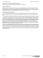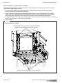
1
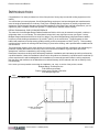
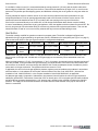
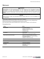
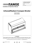
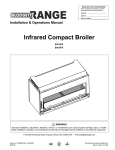
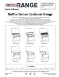
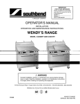
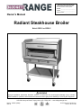
IMPORTANT FOR FUTURE REFERENCE
Please complete this information and retain
this manual for the life of the equipment:
Model #: __________________________
Serial #: __________________________
Date Purchased: ___________________
Owner’s Manual
Radiant Steakhouse Broiler
Models BSB-36 and BSB-45
WARNING
Improper installation, adjustment, alteration, service, or maintenance can cause property damage, injury, or death.
Read installation, operation, and maintenance instructions thoroughly before installing or servicing this equipment.
1100 Old Honeycutt Road, Fuquay-Varina, NC 27526 USA • www.blodgettrange.com
MANUAL 1190951 (02/09)
$30.00
RADIANT STEAKHOUSE BROILER
MANUAL SECTION SR
SAFETY PRECAUTIONS
RADIANT STEAKHOUSE BROILER
SAFETY PRECAUTIONS
Before installing and operating this equipment, be sure everyone involved in its operation is fully trained and aware of
precautions. Accidents and problems can be caused by failure to follow fundamental rules and precautions.
The following symbols, found throughout this manual, alert you to potentially dangerous conditions to the operator,
service personnel, or to the equipment.
DANGER
This symbol warns of immediate hazards that will result in severe injury or death.
WARNING
This symbol refers to a potential hazard or unsafe practice that could result in injury or
death.
CAUTION
This symbol refers to a potential hazard or unsafe practice that could result in injury,
product damage, or property damage.
NOTICE
This symbol refers to information that needs special attention or must be fully understood,
even though not dangerous.
WARNING
FIRE HAZARD
FOR YOUR SAFETY
Do not store or use gasoline or other flammable vapors and liquids in the vicinity of cooking appliances.
Keep area around cooking appliances free and clear of combustibles.
Purchaser of equipment must post in a prominent location detailed instructions to be followed in the event the
operator smells gas. Obtain the instructions from the local gas supplier.
WARNING
BURN HAZARD
Contact with hot surfaces will cause severe burns. Always use caution when operating cooking appliances.
WARNING
EXPLOSION AND ASPHYXIATION HAZARD
In the event a gas odor is detected, shut down equipment at the main gas shutoff valve and immediately call the
emergency phone number of your gas supplier.
Improper ventilation can result in headaches, drowsiness, nausea, and could result in death. Do not obstruct the
flow of combustion and ventilation air to and from cooking appliances.
WARNING
ELECTRIC SHOCK HAZARD
For appliances that use electric power, disconnect the power to the appliance before cleaning. Do not remove
panels that require tools to remove.
NOTICE
Blodgett Range appliances are intended for commercial use only. Not for household use.
Warranty will be void if service work is performed by other than a qualified technician, or if other than genuine
Blodgett Range replacement parts are installed.
Give this Owner’s Manual and important papers to the proper authority to retain for future reference.
Copyright © 2009 by Blodgett Range. All rights reserved. Published in the United States of America.
PAGE 2 OF 20
OWNER’S MANUAL 1190951 (02/09)
RADIANT STEAKHOUSE BROILER
INTRODUCTION
INTRODUCTION
Congratulations! You have purchased one of the finest pieces of heavy-duty commercial cooking equipment on the
market.
You will find that your new equipment, like all Blodgett Range equipment, has been designed and manufactured to
meet the toughest standards in the industry. Each piece of Blodgett Range equipment is carefully engineered and
designs are verified through laboratory tests and field installations. With proper care and field maintenance, you will
experience years of reliable, trouble-free operation. For best results, read this manual carefully.
RETAIN THIS MANUAL FOR FUTURE REFERENCE.
This manual is for the Blodgett Range Radiant Steakhouse Broiler, which may be mounted on a stand, a cabinet, a
refrigeration base, or a countertop. The serial plate is located in the rear right lower corner (see Figure 1 below).
Blodgett Range steakhouse broilers are unique in design. They utilize Blodgett Range’s high performance radiant
burners to provide broiling temperatures of up to 850°F (454°C) on the rack surface. The spent gases are then
baffled and transferred to the top searing griddle providing a uniform temperature of 650°F (343°C). This secondary
cooking surface is perfect for searing meat and locking in juices before broiling, and is provided without additional fuel
cost or burners.
The broiler design supplies 100% clean primary air to the burners, ensuring efficient combustion and maintaining full
production capacity and maximum recovery even in the most severe conditions of grease vapors and smoke
atmospheres, which are created during any broiling process.
Read these instructions carefully before attempting installation. Installation and initial startup should be performed by
a qualified installer. Unless the installation instructions for this product are followed by a qualified service technician (a
person experienced in and knowledgeable of the installation of commercial gas and/or electric cooking equipment)
then the terms and conditions on the Manufacturer’s Limited Warranty will be rendered void and no warranty of any
kind shall apply.
In the event you have questions concerning the installation, use, care, or service of the product, contact:
Blodgett Range Technical Service
1100 Old Honeycutt Road
Fuquay-Varina, North Carolina 27526 USA
www.blodgettrange.com
Figure 1
Location of Serial Plate
Location of Serial Plate
(on rear of unit)
OWNER’S MANUAL 1190951 (02/09)
PAGE 3 OF 20
SPECIFICATIONS
RADIANT STEAKHOUSE BROILER
SPECIFICATIONS
NOTICE
Local codes regarding installation vary greatly from one area to another. The National Fire Protection Association,
Inc. states in its NFPA 96 latest edition that local codes are the “authority having jurisdiction” when it comes to
installation requirements for equipment. Therefore, installations must comply with all local codes, or in the absence
of local codes, with the National Fuel Gas Code, ANSI Z223.1, Natural Gas Installation Code, CAN/CGA-B149.1,
or the Propane Installation Code CAN/CGA-B149.2, as applicable, including:
1. The appliance and its individual shutoff valve must be disconnected from the gas supply piping system during
any pressure testing of that system at test pressures in excess of 1/2 psi (3.45 kPa).
2. The appliance must be isolated from the gas supply piping system by closing its individual manual shutoff
valve during any pressure testing of the gas supply piping system at test pressures equal to or less than 1/2
psi (3.45 kPa).
Blodgett Range reserves the right to change specifications and product design without notice. Such revisions do
not entitle the buyer to corresponding changes, additions, or replacements for previously purchased equipment.
This product is intended for commercial use only, not for household use.
CLEARANCES
There must be adequate clearance between the broiler and adjacent construction due to the heat generated by the
broiler. Clearance must also be provided for servicing and for operation.
The minimum clearance from non-combustible construction is 6 inches (152 mm) on the sides and rear (to permit
combustion air to enter the rear of the broiler). To service the broiler components, all models require at least 6 inches
(152 mm) accessibility-clearance on the right and left side.
Adequate clearance must be provided in front of the broiler for operation and cleaning.
The high-temperature flue products from the broiler burners flow out through a flue chamber at the top rear of the
broiler. Installation under a vented hood is recommended.
WARNING
MINIMUM CLEARANCES FROM COMBUSTIBLE CONSTRUCTION
The stand mount, cabinet mount and countertop model require a minimum clearance from combustible surfaces of
6 inches (152 mm) on the sides and rear.
PAGE 4 OF 20
OWNER’S MANUAL 1190951 (02/09)
RADIANT STEAKHOUSE BROILER
SPECIFICATIONS
DIMENSIONS
Figure 2
Dimensions in Inches (Millimeters)
Minimum Clearances 6" (152) Rear and Sides
A
41.5" (1054)
38.75" (984)
57.0"
(1448)
Floor to
Griddle Surface
52.5" (1334)
Floor to
Broiler Surface
(Lowest Position)
41.0" (1041)
FRONT VIEW
RIGHT SIDE VIEW
Total BTU’s
Nat Gas
Propane
Crated Weight
2
84,000
73,000
512 lbs (232 kg)
3
126,000
109,500
616 lbs (279 kg)
Width “A”
Number
Burners
BSB-36
36" (914 mm)
BSB-45
45" (1143 mm)
Model Number
VENTILATION
WARNING
Improper ventilation can result in personal injury or death. Ventilation, which fails to properly remove flue products,
can cause headaches, drowsiness, nausea, or could result in death.
The flue vent, located at the top rear of the unit, must not be blocked or covered at any time.
All gas appliances must be installed in such a manner that the flow of combustion and ventilation air is not
obstructed. Provisions for adequate air supply must be provided.
NOTICE
Proper ventilation is the owner’s responsibility. Any problem due to improper ventilation will not be covered by the
warranty.
Do not obstruct the rear of the broiler since combustion air enters through this area. Be sure to inspect and clean
the ventilation system according to the ventilation equipment manufacturer’s instructions.
OWNER’S MANUAL 1190951 (02/09)
PAGE 5 OF 20
SPECIFICATIONS
RADIANT STEAKHOUSE BROILER
If a ventilation canopy is used, it is recommended that the canopy extend 6" (152 mm) past the broiler and that the
bottom edge be located 6'6" (1980 mm) from the floor. Filters should be installed at an angle of 45° or more from the
horizontal. This position prevents dripping grease, and facilitates collecting the run-off grease in a drip pan under the
filter.
A strong exhaust fan tends to create a vacuum in the room and may interfere with burner performance or may
extinguish pilot flames. Fresh air openings approximately equal to the fan area will relieve such a vacuum. The
exhaust fan should be installed at least 2" (51 mm) above the vent opening on the top rear of the broiler.
If the broiler is connected directly to an outside flue, a CSA design-certified down draft diverter must be installed.
In case of unsatisfactory performance by any gas appliance, check the appliance with the exhaust fan turned OFF. Do
this only long enough to check whether doing so corrects any problems with equipment performance. Then turn the
exhaust fan back on and let it run to remove any exhaust that may have accumulated during the test.
GAS SUPPLY
The broiler is design-certified for operation on natural or propane gases. The broiler is shipped configured and
adjusted for the type of gas specified by the purchaser, which is indicated on the serial plate (see Figure 1 on page 3).
Connect the broiler ONLY to the type of gas for which it is configured and adjusted.
Gas Type
Natural Gas
Propane
Total BTU/hour
42,000 Per
Burner
36,500 Per
Burner
Burner Orifice
Bar Pilot.
Min. Supply Pressure
Manifold Pressure
No. 36 (P/N 1006436)
No. 75 (P/N 1176664)
7" W.C.
6" W.C.
No. 51 (P/N 1006451)
No. 79 (P/N 1176665)
11" W.C.
10" W.C.
Models with a rear gas connection have a 1" rear gas connection to an external regulator that is located at the rear
bottom corner on the right side. Models with a front gas supply are connected by unions assembled to the front
manifold.
Minimum supply pressure is 7" W.C. for natural gas, 11" W.C. for propane. An external pressure regulator and shutoff
valve are provided. If using a flexible-hose gas connection, the inside diameter of the hose must not be smaller than
the connector on the broiler, and must comply with ANSI Z21.69. Provide an adequate means of restraint to prevent
undue strain on the gas connection. Test pressure should not exceed 14" W.C.
If applicable, the vent line from the gas appliance pressure regulator must be installed to the outdoors in accordance
with local codes, or in the absence of local codes, with the National Fuel Gas Code, ANSI Z223.1, Natural Gas
Installation Code, CAN/CGA-B149.1, or the Propane Installation Code CAN/CGA-B149.2, as applicable.
An adequate gas supply is imperative. Undersized or low-pressure lines will restrict the volume of gas required for
satisfactory performance. Fluctuations of more than 25% on natural gas or 10% on propane gas will create problems
and affect burner-operating characteristics. A 1/8" pressure tap is located on the manifold to measure the manifold
pressure. The supply line to the broiler should be no smaller than the inside diameter of the pipe on the broiler to
which it is connected.
PAGE 6 OF 20
OWNER’S MANUAL 1190951 (02/09)
RADIANT STEAKHOUSE BROILER
OPERATION
OPERATION
DANGER
EXPLOSION HAZARD
In the event a gas odor is detected, shut down equipment at the main shutoff valve. Immediately call the
emergency phone number of your gas supplier.
CAUTION
If the broiler pilots should go out, the flow of gas to the broiler burners is NOT interrupted. Consequently, it is the
responsibility of the operator to check the ignition of the burners immediately EVERY TIME the broiler is turned on.
Should ignition fail after 10 seconds, turn off burners, wait 5 minutes, and then try again.
OPERATION OF RADIANT STEAKHOUSE BROILER
The location of the broiler controls and other components are shown in Figure 3 on the next page.
Blodgett Range radiant steakhouse broilers offer the intensity to broil the thickest cuts of meat at reduced cook times,
the adjustability to finish delicate dishes to perfection, and the versatility of a griddle surface to sear and prepare nonbroiled menu items.
Blodgett Range radiant steakhouse broilers require a preheat time of 5 minutes to stabilize rack temperatures and 30
minutes for the griddle to reach even heat distribution temperatures for searing. The burner flame may lift until
temperatures stabilize and reach operating temperature. When the ceramic tiles appear to glow evenly red, the
broiler is ready to accept product. The broiling rack adjusts to nine heights, and rolls out for easy access.
The cooking area has removable racks and drip trays for cleaning. As food cooks, drippings drain into a grease
drawer located on the front of the unit next to the burner control knobs. To operate the broiler, do the following:
1. Light the constant-burning pilots located near the front of the broiler burners (unless they are already lit).
2. If necessary, pull out and empty the bottom grease drawer and the griddle grease chute. Keep the drip pans in
place below the rack when broiling! Without them in place, excessive air will be pulled past the burners, reducing
temperature and cooking efficiency.
3. Turn the burner controls to HIGH and visually check that the burners have ignited. When the burners ignite, a blue
flame will carry across the ceramic tiles. Flames may lift from the burner until temperatures stabilize. When the
burner control is set to HIGH, the ceramic tips will glow red across the entire tile. When the burner control is set
to LOW, the ceramics tips will glow red across 2/3 of each tile. (If the flame continues to lift after 10 minutes, or if
the flame remains yellow and sooting occurs, the broiler requires adjustment by a service technician.)
4. If searing the food to mark it with grid marks is desired, before placing food on the broiler rack move the rack to its
highest position and allow the burners to operate on HIGH for five minutes to heat the rack surface.
5. Turn the burner control to HIGH or LOW (as appropriate for the food to be cooked).
6. Raise or lower the broiler rack to the height appropriate for the food to be cooked. A clicking noise will indicate
changes in rack position when lowering the rack. To lower the rack, simply push down on the ball knob. To raise
the rack, depress the paddle handle.
7. Pull out the rack, place food on the rack, and slide the rack back into the broiler. (It is recommended the rack be in
the lowest position when loading food.)
8. Broil food for the appropriate time, turning it when appropriate. Periodically check the broiler grease drawer and
grease chute and empty them when necessary.
9. When done broiling, turn the burner controls to OFF. (To keep the broiler rack hot in order to mark food with sear
marks without preheating, turn the burner controls to LOW and move the broiler rack to its highest position.)
OWNER’S MANUAL 1190951 (02/09)
PAGE 7 OF 20
OPERATION
RADIANT STEAKHOUSE BROILER
Figure 3
Broiler Controls and Components
Flue Vent Chamber
Removable
Grease Chute
Pilot Adjustment
Access Hole
Removable
Heavy-Duty
Broil Rack
Removable
Stainless Steel
Drip Pan
Gas Regulator with
1" Rear Connection
Variable High-Low-Off
Independent Gas
Adjustment
Release Paddle
Nine-Position Rack
Adjustment Arm
Removable
Grease Drawer
Keep the drip pans in place below the rack when broiling! Without them in place,
excessive air will be pulled past the burners, reducing temperature and cooking efficiency.
LIGHTING AFTER GAS HAS BEEN SHUT OFF
When turning on the main gas supply to an appliance or a group of appliances, do the following:
1. Make sure that all the control valves and power switches of all the appliances are in the OFF position.
2. Turn on the main gas supply valve.
3. Light the standing pilots of each connected appliance.
LIGHTING BROILER PILOTS
The pilots should burn continuously unless the broiler is to be completely shut down. The broiler cavity has two or
three pilots, one near each burner. If the pilots are extinguished, the pilot gas supply is NOT automatically interrupted.
To light the pilots, do the following:
1. Turn the control valves on the front of the broiler to OFF.
2. Turn on the gas supply to the broiler (if not already on).
3. Light the pilots.
SHUTDOWN OF BROILER
To place the broiler in a standby state (ready for use), turn the burner control valves to OFF. The pilots will remain lit.
To completely shut down the broiler for an extended period (or prior to disconnecting the gas supply), turn OFF the
manual shutoff valves of all gas supply connections. (This will extinguish all pilots.)
PAGE 8 OF 20
OWNER’S MANUAL 1190951 (02/09)
RADIANT STEAKHOUSE BROILER
CLEANING & MAINTENANCE
CLEANING & MAINTENANCE
WARNING
Shut off the gas supply to the appliance before cleaning or performing maintenance on any gas appliance.
The appliance may be equipped with a restraint device to limit its movement in order to prevent damage to the
gas connection. If disconnection of this restraint is necessary to move the appliance for cleaning or
maintenance, reconnect the restraint when the appliance is moved back to its original installed position.
Blodgett Range equipment is sturdily constructed of the best materials and is designed to provide durable service
when treated with ordinary care. To provide the best performance, your equipment must be maintained in good
condition and cleaned daily. Naturally, the periods for this care and cleaning depend on the amount and degree of
usage.
Following daily and periodic maintenance procedures will enhance long life for your equipment. Climatic conditions
(such as salt air) may require more thorough and frequent cleaning or the life of the equipment could be adversely
affected.
Keep exposed, cleanable areas of the broiler clean at all times. (See next page for instructions on cleaning stainless
steel and baked-enamel surfaces.)
DAILY CLEANING AND MAINTENANCE
To prevent excess smoking, the broiler grids, bottom grease drawer, griddle grease chute, and the other broiler
components must be kept clean of food remnants. Use a wire brush or similar scraping utensil. DO NOT use steel
wool or a similar scrub pad that will leave small particles, which can get into food. The daily cleaning procedure is as
follows:
1. Use a Norton Alundum Griddle Brick to clean the griddle. Never wash a griddle with soap and water.
2. Remove the griddle grease chute and clean it.
3. Move the broiling rack to the low position. Pull out the rolling broiler rack.
4. Lift out the broiler grids and clean them with a wire brush or non-toxic solvent.
5. Lift out the drip shields and clean them with soap and water.
6. With the rolling rack pulled-out to its stop, clean all parts where residue can collect.
7. Clean all parts of the raising and lowering frame.
8. Lubricate bearings with cooking oil (this helps to extend the life of the bearings).
9. Reassemble broiling rack drip shields and grids.
10. Remove the bottom grease drawer and clean it.
11. Wipe clean all exterior surfaces.
12. Check that nothing has been placed on top of the broiler flue (which will block the escape of combustion exhaust).
13. Check that the air-intake openings on the rear of the broiler are not obstructed.
MONTHLY CLEANING AND MAINTENANCE
The following tasks should be performed monthly:
1. Check for proper pilot operation. The flame on each pilot should be just large enough to extend along the flame
carrier to the burner surface. If adjustment is necessary, call for service.
2. Check for proper burner operation. When the burner control is set to HIGH, a blue flame will carry across the
ceramics tiles. The ceramics tile tips will glow red across entire tile. When the burner control is set to LOW, the
ceramics tips will glow red across 2/3 of each tile. If the flame is yellow or sooting occurs, request adjustment by a
service technician.
OWNER’S MANUAL 1190951 (02/09)
PAGE 9 OF 20
CLEANING & MAINTENANCE
RADIANT STEAKHOUSE BROILER
SEMIANNUAL CLEANING AND MAINTENANCE
At least twice a year the venting system should be examined and cleaned.
CARE OF GRIDDLES
The griddle should be carefully cared for in order to avoid possible damage. Use a Norton Alundum Griddle Brick to
clean the griddle. Do not use any type of steel wool because small particles may be left on the surface and get into
food products. Never allow water on a hot griddle, and never wash it with soap and water. Do not strike the griddle
with utensils as this will cut and pit the griddle plate, leaving it rough and hard to clean.
STAINLESS-STEEL SURFACES
To remove normal dirt, grease and product residue from stainless steel surfaces that operate at LOW temperature,
use ordinary soap and water (with or without detergent) applied with a sponge or cloth. Dry thoroughly with a clean
cloth.
To remove BAKED-ON grease and food splatter, or condensed vapors; apply cleanser to a damp cloth or sponge and
rub cleanser on the metal in the direction of the polishing lines on the metal. Rubbing cleanser, as gently as possible,
in the direction of the polished lines will not mar the finish of the stainless steel. NEVER RUB WITH A CIRCULAR
MOTION. Soil and burnt deposits, which do not respond to the above procedure, can usually be removed by rubbing
the surface with SCOTCH-BRITE scouring pads or STAINLESS scouring pads. DO NOT USE ORDINARY STEEL
WOOL as any particles left on the surface will rust and further spoil the appearance of the finish. NEVER USE A
WIRE BRUSH, STEEL SCOURING PADS (EXCEPT STAINLESS), SCRAPER, FILE OR OTHER STEEL TOOLS.
Surfaces, which are marred, collect dirt more rapidly and become more difficult to clean. Marring also increases the
possibility of corrosive attack. Refinishing may then be required.
“Heat tint” is darkened areas that sometimes appear on stainless steel surfaces where the area has been subjected to
excessive heat. These darkened areas are caused by thickening of the protective surface of the stainless steel and
are not harmful. Heat tint can normally be removed by the foregoing, but tint which does not respond to this procedure
calls for a vigorous scouring in the direction of the polish lines using SCOTCH-BRITE scouring pads or a STAINLESS
scouring pad in combination with a powered cleanser. Heat tint may be lessened by reducing heat to the equipment
during slack periods.
PAGE 10 OF 20
OWNER’S MANUAL 1190951 (02/09)
RADIANT STEAKHOUSE BROILER
INSTALLATION
INSTALLATION
NOTICE
These installation procedures must be followed by qualified personnel or warranty will be void.
Local codes regarding installation vary greatly from one area to another. The National Fire Protection Association,
Inc. states in its NFPA 96 latest edition that local codes are the “authority having jurisdiction” when it comes to
installation requirements for equipment. Therefore, installations must comply with all local codes, or in the absence
of local codes, with the National Fuel Gas Code, ANSI Z223.1, Natural Gas Installation Code, CAN/CGA-B149.1,
or the Propane Installation Code CAN/CGA-B149.2, as applicable, including:
1. The appliance and its individual shutoff valve must be disconnected from the gas supply piping system during
any pressure testing of that system at test pressures in excess of 1/2 psi (3.45 kPa).
2. The appliance must be isolated from the gas supply piping system by closing its individual manual shutoff valve
during any pressure testing of the gas supply piping system at test pressures equal to or less than 1/2 psi (3.45
kPa).
STEP 1: UNPACKING
IMMEDIATELY INSPECT FOR SHIPPING DAMAGE
All containers should be examined for damage before and during unloading. The freight carrier has assumed
responsibility for its safe transit and delivery. If damaged equipment is received, either apparent or concealed, a
claim must be made with the delivering carrier.
Apparent damage or loss must be noted on the freight bill at the time of delivery. The freight bill must then be
signed by the carrier representative (Driver). If the bill is not signed, the carrier may refuse the claim. The carrier
can supply the necessary forms.
A request for inspection must be made to the carrier within 15 days if there is concealed damage or loss that is not
apparent until after the equipment is uncrated. The carrier should arrange an inspection. Be certain to hold all
contents plus all packing material.
1. Cut the banding straps and remove the corrugated cardboard surrounding the broiler. Do not remove any of the
attached tags or labels until the broiler is installed and working properly.
2. Cut the banding strap holding the broiler to the wooden skid.
3. If installing the broiler on a stand, go to Step 2a.
If installing the broiler on a countertop, go to Step 2b.
OWNER’S MANUAL 1190951 (02/09)
PAGE 11 OF 20
INSTALLATION
RADIANT STEAKHOUSE BROILER
STEP 2A: MOUNT ON HEAVY DUTY STAND
The stand is crated separately, but is shipped with the broiler. Depending on the shipping requirements, the broiler
may already be assembled to the stand.
1. The broiler will be attached to the stand using four ¼"-20 bolts and lock washers provided with the stand.
Remove the bolts and lock washers from the stand.
2. Lift the broiler (using two people is recommended). (Depending on the size and weight of the unit, it may be
helpful to remove the griddle plate before lifting the broiler. To do so, remove the body sides to access griddle
plate mounting bolts.) Place the broiler on the stand so the holes in the mounting flange align with the
corresponding holes in the stand. The valve panel flange should sit flush with front frame of the stand. Secure the
broiler to the stand with the ¼"-20 bolts and lock washers.
3. Go on to Step 3.
Figure 4
Mounting Broiler on Stand
If assembled broiler is too heavy to lift, remove side panels
and then remove griddle top by removing four bolts.
Fasten broiler to stand with four 1/4-inch bolts here.
PAGE 12 OF 20
OWNER’S MANUAL 1190951 (02/09)
RADIANT STEAKHOUSE BROILER
INSTALLATION
STEP 2B: ATTACH COUNTERTOP LEGS
The broiler may set on a countertop using short legs. Be sure that the countertop is rated to support the crated weight
of the broiler (see Figure 2 on page 5). The model number is shown on the serial plate located in the rear right corner
of you broiler (see Figure 1 on page 3).
1. With the broiler lying on its back side, screw the four legs tightly into the leg pads, as shown below. Lift the broiler
(using two people is recommended) and set it in place on the countertop. Adjust the legs as needed to level unit.
2. Position the broiler to the specified minimum clearances (see page 4).
3. Go on to Step 3.
Figure 5
Installation on Countertop
Screw legs into leg pads here.
OWNER’S MANUAL 1190951 (02/09)
PAGE 13 OF 20
INSTALLATION
RADIANT STEAKHOUSE BROILER
STEP 3: CONNECT GAS SUPPLY
If the broiler is being installed at over 2,000 feet (610 meters) altitude and that information was not specified when
ordered, contact the appropriate authorized Blodgett Range Service Representative or the Blodgett Range Service
Department. Failure to install with proper orifice sizing will result in poor performance and may void the warranty.
The broiler is design-certified for operation on natural or propane gases. The broiler is shipped configured and
adjusted for the type of gas specified by the purchaser, which is indicated on the serial plate (see Figure 1 on page 3).
Connect the broiler ONLY to the type of gas for which it is configured and adjusted.
The broiler will have a 1" NPT female thread in the regulator at the rear of the unit, or may be connected by the front
manifold when connected to a battery of other sectional equipment.
Minimum supply pressure is 7" W.C. for natural gas, 11" W.C. for propane. An external pressure regulator is provided.
If using a flexible-hose gas connection, the inside diameter of the hose must not be smaller than the connector on the
broiler, and must comply with ANSI Z21.69. Provide an adequate means of restraint to prevent undue strain on the
gas connection.
If applicable, a vent line from the gas appliance pressure regulator must be installed to the outdoors in accordance
with local codes, or in the absence of local codes, with the National Fuel Gas Code, ANSI Z223.1, Natural Gas
Installation Code, CAN/CGA-B149.1, or the Propane Installation Code CAN/CGA-B149.2, as applicable.
An adequate gas supply is imperative. Undersized or low-pressure lines will restrict the volume of gas required for
satisfactory performance. Fluctuations of more than 25% on natural gas or 10% on propane gas will create problems
and affect burner-operating characteristics. A 1/8" pressure tap is located on the manifold to measure the manifold
pressure. The supply line to the broiler should be no smaller than the inside diameter of the pipe on the broiler to
which it is connected.
CAUTION
ALL PIPE JOINTS AND CONNECTIONS MUST BE TESTED THOROUGHLY FOR GAS LEAKS. USE ONLY
SOAPY WATER FOR TESTING ON ALL GASES. NEVER USE AN OPEN FLAME TO CHECK FOR GAS LEAKS.
ALL CONNECTIONS MUST BE CHECKED FOR LEAKS AFTER THE APPLIANCE HAS BEEN PUT INTO
OPERATION. TEST PRESSURE SHOULD NOT EXCEED 14" W.C.
1. Check that the control valves on the broiler are in the OFF position.
2. Purge the gas supply line to clean out dust, dirt, or other foreign matter before connecting the line to the broiler.
3. For stand mount and countertop mounting, connect the gas supply to the inlet at right rear corner.
CAUTION
HOLD THE INLET SUPPLY PIPE WITH A WRENCH WHEN TIGHTENING ADDED FITTINGS TO AVOID
DAMAGE TO THE REGULATOR, VALVE, AND OTHER COMPONENTS.
4. Turn on the gas and check for leaks using soapy water.
STEP 4: CHECK THE INSTALLATION
1. Check that all screws and bolts are tightened.
2. Check that the gas connection has been made correctly.
3. Move the broiler into the final position at which it will be operated.
4. Check that the broiler is level.
5. Check that the appropriate minimum clearances are satisfied (see page 4), including adequate clearance for
combustion air to enter the rear of the broiler.
6. Check that there is sufficient clearance to pull out the broiler rack, grease drawer, and griddle grease chute; and
to operate the rack-height adjustment lever.
7. Check that adequate ventilation (fresh air supply and hood exhaust) is available to the room in which the
appliance will operate.
8. Wipe clean all surfaces.
PAGE 14 OF 20
OWNER’S MANUAL 1190951 (02/09)
RADIANT STEAKHOUSE BROILER
INSTALLATION
STEP 5: CHECK BROILER OPERATION
1. Turn the gas supply on. Immediately check all gas connections for leaks using soapy water.
2. Light the pilots and check that the pilot flames are large enough to extend along the flame carrier to the burner
surface. If not, adjust the pilots (see page 17).
3. Turn the burner control to HIGH and visually check that the burners have ignited. When the burners ignite, a blue
flame will carry across the ceramics tiles. Flames may lift from the burners until temperatures stabilize. When the
burner control is set to HIGH, the ceramics tips will glow red across the entire tile. When the burner control is set
to LOW, the ceramics tips will glow red across 2/3 of each tile. (If the flame continues to lift after 10 minutes or if
flame remains yellow and sooting occurs, adjust the burner venturi.)
4. Check that the gas supply is adequate by simultaneously turning on all burners of all appliances connected to the
same gas supply to their highest setting, then again checking that the broiler’s pilot and burner flames have
correct appearance and height.
5. Spread over the hot griddle three or four ounces of beef suet, or as a substitute, baking soda, to season it.
6. Turn off all burners and allow the broiler to cool.
STEP 6: WIPE-CLEAN AND SHUT-DOWN APPLIANCE
1. Wipe clean all surfaces.
2. Unless the broiler is to be placed in service immediately, shut off the gas supply.
3. Make sure that a copy of this manual is available to the people who will operate and maintain the broiler.
OWNER’S MANUAL 1190951 (02/09)
PAGE 15 OF 20
RADIANT STEAKHOUSE BROILER
SERVICE
WARNING
ADJUSTMENTS AND SERVICE WORK MAY BE PERFORMED ONLY BY A QUALIFIED TECHNICIAN WHO IS
EXPERIENCED IN, AND KNOWLEDGEABLE OF, THE OPERATION OF COMMERCIAL COOKING
EQUIPMENT. TO ASSURE YOUR CONFIDENCE, CONTACT YOUR AUTHORIZED SERVICE AGENCY FOR
RELIABLE SERVICE, DEPENDABLE ADVICE OR OTHER ASSISTANCE, AND FOR GENUINE FACTORY
PARTS.
NOTICE
INSTALLATION OF OTHER THAN GENUINE BLODGETT RANGE PARTS WILL VOID THE WARRANTY ON
THIS EQUIPMENT.
The serial plate is located in the rear right corner (see Figure 1 on page 3).
Replacement parts (including parts not listed in this manual) may be ordered either through a Blodgett Range
Authorized Parts Distributor or a Blodgett Range Authorized Service Agency.
When ordering parts, please supply the Model Number, Serial Number, Part Number, and Part Description.
TROUBLESHOOTING
Problem
Look for -
Not enough heat
– Low pressure in gas supply
– Restriction in gas piping and/or valves
– Misalignment of orifice to burner venturi
– Clogged burner orifice
– Incorrect burner orifice
Too much heat
– Incorrect orifices
– Malfunctioning or incorrectly set pressure regulator
Burner flame has excessive yellow tipping
– Obstruction of combustion-air intake on rear of broiler
– Exhaust gases blocked by objects sitting on top of broiler
– Low pressure in gas supply
– Misalignment of orifice to burner venturi
Burner flame fluttering
– Low gas pressure or obstruction in orifice
Burner flame lifting
– High gas pressure or air shutter on venturi out of adjustment
Slow burner ignition
– Pilot flame out of adjustment
Pilot outage
– Pilot flame out of adjustment
– Draft condition
– Pilot orifice clogged
PAGE 16 OF 20
OWNER’S MANUAL 1190951 (02/09)
RADIANT STEAKHOUSE BROILER
ACCESS TO SERVICEABLE PARTS
Some serviceable parts are only accessible by removing body side panels or the burner cover.
The burner cover is fastened with ten sheet-metal screws. To remove the burner cover, remove these screws. The
burner cover can then be pulled forward and removed. Each body side panel is fastened with seven sheet-metal
screws, three in the front and four at the rear. Remove body-side screws and slide the body side towards the rear
and away from the unit.
Figure 6
Access to Serviceable Parts
Pilot Adjustment
Screw
Burner Cover
Burner Venturi
Body Side Panel
ADJUSTMENT OF BROILER PILOTS
The pilots are adjusted at the factory. If later the pilots are over-adjusted to the point where the flame is leaving its
port, or “blowing off,” the result is an unstable condition in which the pilot may extinguish. If necessary, adjust the
pilots using the following procedure:
1. If necessary, light the pilots.
2. Locate the pilot adjustment screw (which adjusts all pilots). It is a small slotted screw located on the pilot valve,
and can be adjusted though an access hole in the burner cover (shown in Figure 6 above).
3. Turn the pilot adjustment screw to adjust the size of the pilot flames. The flame on each pilot should be large
enough to extend along the flame carrier to the burner surface.
OWNER’S MANUAL 1190951 (02/09)
PAGE 17 OF 20
RADIANT STEAKHOUSE BROILER
ADJUSTMENT OF BROILER BURNERS
The burners are adjusted at the factory. Adjustment may be required to achieve proper operation due to elevation
change or other variables. Remove the burner cover to adjust the air shutter on each burner venturi (shown in Figure
6 on the previous page) to achieve proper combustion and optimum burn.
ADJUSTMENT OF GAS PRESSURE REGULATOR
The pressure regulator is located at the rear right lower corner of the broiler. The regulator is preset for 6" W.C. for
natural gas, or 10" W.C. for propane gas. If adjustment is necessary, do the following:
1. Turn the broiler control knobs to OFF.
2. Attach a pressure-measuring device to the 1/8" NPT connector located on the main manifold (accessible by
removing the grease drawer).
3. Turn the broiler control knobs to HIGH. With the burners lit, check the manifold pressure. The pressure should be
6" W.C. (for natural gas) or 10" W.C. (for propane gas).
4. If necessary, adjust the pressure by unscrewing the top of the pressure regulator (use a screwdriver) to expose
the adjustment screw underneath. Rotating the adjustment screw clockwise increases the manifold pressure.
5. After the pressure has been adjusted, turn the broiler control knobs to OFF, and replace the top cap of the
pressure regulator. Disconnect the pressure-measuring device and replace the plug into the manifold.
PARTS
The following table describes the serviceable parts. For parts not listed, contact a Blodgett Range Authorized Parts
Distributor or a Blodgett Range Authorized Service Agency.
PARTS LIST
NATURAL GAS
Part Number
1006436
DESCRIPTION
Quantity
BSB-36
BSB-45
BURNER ORIFICE
2
3
1176008
BURNER VALVE
2
3
1184384
PILOT ADJUST
1
1
1167782
REGULATOR,PRESS,WC @ 6",NAT
1
1
1130399
BURNER, HI-GLOW
2
3
1130398
VENTURI ASSEMBLY, HI-GLOW
2
3
1-5371
CERAMIC TILE
20
30
1184192
KNOB
2
3
PARTS LIST
PROPANE GAS
Part Number
1006451
DESCRIPTION
Quantity
BSB-36
BSB-45
BURNER ORIFICE
2
3
1176009
BURNER VALVE
2
3
1184384
PILOT ADJUST
1
1
1167783
REGULATOR,PRESS,WC @10",PROP
1
1
1130399
BURNER, HI-GLOW
2
3
1130398
VENTURI ASSEMBLY, HI-GLOW
2
3
1-5371
CERAMIC TILE
20
30
1184192
KNOB
2
3
PAGE 18 OF 20
OWNER’S MANUAL 1190951 (02/09)
RADIANT STEAKHOUSE BROILER
Notes:
OWNER’S MANUAL 1190951 (02/09)
PAGE 19 OF 20
RADIANT STEAKHOUSE BROILER
RADIANT STEAKHOUSE BROILER
Stand Mount, Countertop, Cabinet Base or Refrigeration Base
A product with the Blodgett Range name incorporates the best in durability and low maintenance. We all
recognize, however, that replacement parts and occasional professional service may be necessary to extend the
useful life of this appliance. When service is needed, contact a Blodgett Range Authorized Service Agency, or your
dealer. To avoid confusion, always refer to the model number, serial number, and type of your appliance.
Blodgett Range
1100 Old Honeycutt Road, Fuquay-Varina, NC 27526
www.blodgettrange.com
PAGE 20 OF 20
OWNER’S MANUAL 1190951 (02/09)