1
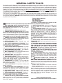
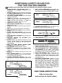
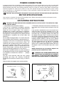
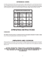
(Model 43-505)
PART NO. 902118 (0112)
Copyright © 2001 Delta Machinery
To learn more about DELTA MACHINERY
visit our website at: www.deltamachinery.com.
For Parts, Service, Warranty or other Assistance,
please call
ESPAÑOL: PÁGINA 19
1-800-223-7278 (In Canada call 1-800-463-3582).
INSTRUCTION MANUAL
Router / Shaper
GENERAL SAFETY RULES
Woodworking can be dangerous if safe and proper operating procedures are not followed. As with all machinery, there
are certain hazards involved with the operation of the product. Using the machine with respect and caution will
considerably lessen the possibility of personal injury. However, if normal safety precautions are overlooked or ignored,
personal injury to the operator may result. Safety equipment such as guards, push sticks, hold-downs, featherboards,
goggles, dust masks and hearing protection can reduce your potential for injury. But even the best guard won’t make
up for poor judgment, carelessness or inattention. Always use common sense and exercise caution in the workshop.
If a procedure feels dangerous, don’t try it. Figure out an alternative procedure that feels safer. REMEMBER: Your
personal safety is your responsibility.
This machine was designed for certain applications only. Delta Machinery strongly recommends that this machine not
be modified and/or used for any application other than that for which it was designed. If you have any questions relative
to a particular application, DO NOT use the machine until you have first contacted Delta to determine if it can or should
be performed on the product.
Technical Service Manager
Delta Machinery
4825 Highway 45 North
Jackson, TN 38305
(IN CANADA: 505 SOUTHGATE DRIVE, GUELPH, ONTARIO N1H 6M7)
WARNING: FAILURE TO FOLLOW THESE RULES MAY RESULT IN SERIOUS PERSONAL INJURY
1. FOR YOUR OWN SAFETY, READ INSTRUCTION
MANUAL BEFORE OPERATING THE TOOL. Learn the
tool’s application and limitations as well as the specific
hazards peculiar to it.
2. KEEP GUARDS IN PLACE and in working order.
3. ALWAYS WEAR EYE PROTECTION. Wear safety
glasses. Everyday eyeglasses only have impact resistant
lenses; they are not safety glasses. Also use face or dust
mask if cutting operation is dusty. These safety glasses
must conform to ANSI Z87.1 requirements. NOTE:
Approved glasses have Z87 printed or stamped on them.
4. REMOVE ADJUSTING KEYS AND WRENCHES. Form
habit of checking to see that keys and adjusting wrenches
are removed from tool before turning it “on”.
5. KEEP WORK AREA CLEAN. Cluttered areas and
benches invite accidents.
6. DON’T USE IN DANGEROUS ENVIRONMENT. Don’t
use power tools in damp or wet locations, or expose them
to rain. Keep work area well-lighted.
7. KEEP CHILDREN AND VISITORS AWAY. All children
and visitors should be kept a safe distance from work area.
8. MAKE WORKSHOP CHILDPROOF – with padlocks,
master switches, or by removing starter keys.
9. DON’T FORCE TOOL. It will do the job better and be
safer at the rate for which it was designed.
10. USE RIGHT TOOL. Don’t force tool or attachment to
do a job for which it was not designed.
11. WEAR PROPER APPAREL. No loose clothing, gloves,
neckties, rings, bracelets, or other jewelry to get caught in
moving parts. Nonslip footwear is recommended. Wear
protective hair covering to contain long hair.
12. SECURE WORK. Use clamps or a vise to hold work
when practical. It’s safer than using your hand and frees
both hands to operate tool.
13. DON’T OVERREACH. Keep proper footing and
balance at all times.
14. MAINTAIN TOOLS IN TOP CONDITION. Keep tools
sharp and clean for best and safest performance. Follow
instructions for lubricating and changing accessories.
15. DISCONNECT TOOLS before servicing and when
changing accessories such as blades, bits, cutters, etc.
16. USE RECOMMENDED ACCESSORIES. The use of
accessories and attachments not recommended by Delta
may cause hazards or risk of injury to persons.
17. REDUCE THE RISK OF UNINTENTIONAL STARTING.
Make sure switch is in “OFF” position before plugging in
power cord. In the event of a power failure, move switch
to the “OFF” position.
18. NEVER STAND ON TOOL. Serious injury could occur if
the tool is tipped or if the cutting tool is accidentally
contacted.
19. CHECK DAMAGED PARTS. Before further use of the
tool, a guard or other part that is damaged should be
carefully checked to ensure that it will operate properly and
perform its intended function – check for alignment of
moving parts, binding of moving parts, breakage of parts,
mounting, and any other conditions that may affect its
operation. A guard or other part that is damaged should be
properly repaired or replaced.
20. DIRECTION OF FEED. Feed work into a blade or
cutter against the direction of rotation of the blade or cutter
only.
21. NEVER LEAVE TOOL RUNNING UNATTENDED.
TURN POWER OFF. Don’t leave tool until it comes to a
complete stop.
22. STAY ALERT, WATCH WHAT YOU ARE DOING, AND
USE COMMON SENSE WHEN OPERATING A POWER
TOOL. DO NOT USE TOOL WHILE TIRED OR UNDER
THE INFLUENCE OF DRUGS, ALCOHOL, OR
MEDICATION. A moment of inattention while operating
power tools may result in serious personal injury.
23. MAKE SURE TOOL IS DISCONNECTED FROM
P O W E R S U P P LY w h i l e m o t o r i s b e i n g m o u n t e d ,
connected or reconnected.
24. THE DUST GENERATED by certain woods and wood
products can be injurious to your health. Always operate
machinery in well ventilated areas and provide for proper
dust removal. Use wood dust collection systems whenever
possible.
25.
WARNING: SOME DUST CREATED BY
POWER SANDING, SAWING, GRINDING, DRILLING,
AND OTHER CONSTRUCTION ACTIVITIES contains
chemicals known to cause cancer, birth defects or other
reproductive harm. Some examples of these chemicals
are:
· lead from lead-based paints,
· crystalline silica from bricks and cement and other
masonry products, and
· arsenic and chromium from chemically-treated lumber.
Your risk from these exposures varies, depending on how
often you do this type of work. To reduce your exposure
to these chemicals: work in a well ventilated area, and
work with approved safety equipment, such as those
dust masks that are specially designed to filter out
microscopic particles.
SAVE THESE INSTRUCTIONS.
Refer to them often and use them to instruct others.
2
ADDITIONAL SAFETY RULES FOR
FOR THE ROUTER/SHAPER
WARNING: FAILURE TO FOLLOW THESE RULES MAY RESULT IN SERIOUS PERSONAL INJURY
1. DO NOT OPERATE THIS MACHINE UNTIL it is
assembled and installed according to the
instructions.
2. OBTAIN ADVICE from your supervisor, instructor,
or another qualified person if you are not familiar
with the operation of this machine.
3. FOLLOW ALL WIRING CODES and recommended
electrical connections.
4. NEVER turn the machine “ON” before clearing the
table of all objects (tools, scraps of wood, etc.).
5. AVOID awkward hand positions. A sudden slip
could allow the hand to contact the cutter.
6. KEEP hands away from cutter.
7. NEVER START THE MACHINE with the workpiece
contacting the cutter.
8. NEVER reach under the table while the machine is
running.
9. KEEP cutters sharp and free from rust and pitch.
10. NEVER ADJUST THE FENCE while the machine is
running.
11. ADJUST THE FENCE HALVES so that the cutter
opening is never more than is required to clear the
cutter.
12. LOCK THE FENCE HARDWARE after making fence
adjustments.
13. PROPERLY SECURE THE CUTTERS before
starting the machine.
14. DO NOT perform any operation freehand. Use the
fence for straight shaping, the miter gauge for edge
shaping, and the starting pin and rub collars for
curve shaping.
15. KEEP THE FRONT MOTOR ACCESS PANEL
CLOSED while operating the machine.
16. USE GUARDS provided with the machine.
17. DO NOT feed a workpiece that is warped, contains
knots, or is embedded with foreign objects, (nails,
staples, etc.).
18. NEVER run the workpiece between the fence and
the cutter.
19. USE A MITER GAUGE and a clamp attachment
when edge shaping work less than 3" wide. Remove
the fence during this operation.
20. PROVIDE SUFFICIENT BEARING surface when
shaping with a starting pin and collar(s) (Figs. B and
C).
21. USE A HEAVY WORKPIECE when shaping with
starting pin and collar(s). DO NOT SHAPE a short,
light workpiece against the collar(s) (Figs. D and E).
Fig. D
WRONG
22. POSITION THE CUTTER below the collar(s) when
shaping with starting pin and collar(s) (Fig. F).
COLLAR
CUTTER
WORK
TABLE
Fig. F
23. FEED WORKPIECE against cutter rotation (Fig. G).
CUTTER ROTATION
FEED
24.
25.
26.
27.
SUFFICIENT
BEARING SURFACE
Fig. B
Fig. G
NEVER PERFORM LAYOUT, assembly, or set-up
work on the table while the machine is running.
TURN THE MACHINE “OFF” AND DISCONNECT
THE MACHINE from the power source before
installing or removing accessories, before adjusting
or changing set-ups, or when making repairs.
TURN THE MACHINE “OFF”, disconnect the
machine from the power source, and clean the
table/work area before leaving the machine. LOCK
THE SWITCH IN THE “OFF” POSITION to prevent
unauthorized use.
ADDITIONAL INFORMATION regarding the safe
and proper operation of this machine is available
from the Power Tool Institute, 1300 Summer
Avenue, Cleveland, OH 44115-2851. Information is
also available from the National Safety Council,
1121 Spring Lake Drive, Itasca, IL 60143-3201.
Please refer to the American National Standards
Institute ANSI 01.1 Safety Requirements for
Woodworking Machines and the U.S. Department
of Labor OSHA 1910.213 Regulations.
SAVE THESE INSTRUCTIONS.
CUTTER
COLLAR
WRONG
CUTTER
COLLAR
Fig. E
CUTTER
COLLAR
RIGHT
CUTTER
COLLAR
RIGHT
Refer to them often
INSUFFICIENT
BEARING SURFACE
and use them to instruct others.
Fig. C
3
POWER CONNECTIONS
A separate electrical circuit should be used for your machines. This circuit should not be less than #12 wire and should
be protected with a 20 Amp time lag fuse. If an extension cord is used, use only 3-wire extension cords which have 3prong grounding type plugs and matching receptacle which will accept the machine’s plug. Before connecting the
motor to the power line, make sure the switch is in the “OFF” position and be sure that the electric current is of the
same characteristics as indicated on the machine. All line connections should make good contact. Running on low
voltage will damage the motor.
WARNING: DO NOT EXPOSE THE MACHINE TO RAIN OR OPERATE THE MACHINE IN DAMP LOCATIONS.
MOTOR SPECIFICATIONS
Your machine is wired for 120 volt, 60 HZ alternating current. Before connecting the machine to the power source,
make sure the switch is in the “OFF” position.
GROUNDING INSTRUCTIONS
WARNING: THIS MACHINE MUST BE GROUNDED WHILE IN USE TO PROTECT THE OPERATOR FROM
ELECTRIC SHOCK.
1. All grounded, cord-connected machines:
2. Grounded, cord-connected machines intended for use
on a supply circuit having a nominal rating less than 150
In the event of a malfunction or breakdown, grounding
volts:
provides a path of least resistance for electric current to
reduce the risk of electric shock. This machine is
If the machine is intended for use on a circuit that has an
equipped with an electric cord having an equipmentoutlet that looks like the one illustrated in Fig. A, the
grounding conductor and a grounding plug. The plug must
machine will have a grounding plug that looks like the plug
be plugged into a matching outlet that is properly installed
illustrated in Fig. A. A temporary adapter, which looks like
and grounded in accordance with all local codes and
the adapter illustrated in Fig. B, may be used to connect
ordinances.
this plug to a matching 2-conductor receptacle as shown
in Fig. B if a properly grounded outlet is not available. The
Do not modify the plug provided - if it will not fit the outlet,
temporary adapter should be used only until a properly
have the proper outlet installed by a qualified electrician.
grounded outlet can be installed by a qualified electrician.
Improper connection of the equipment-grounding
The green-colored rigid ear, lug, and the like, extending
conductor can result in risk of electric shock. The
from the adapter must be connected to a permanent
conductor with insulation having an outer surface that is
ground such as a properly grounded outlet box. Whenever
green with or without yellow stripes is the equipmentthe adapter is used, it must be held in place with a metal
grounding conductor. If repair or replacement of the
screw.
electric cord or plug is necessary, do not connect the
equipment-grounding conductor to a live terminal.
NOTE: In Canada, the use of a temporary adapter is not
permitted by the Canadian Electric Code.
Check with a qualified electrician or service personnel if
the grounding instructions are not completely understood,
or if in doubt as to whether the machine is
properly
WARNING: IN ALL CASES, MAKE CERTAIN THE
grounded.
RECEPTACLE IN QUESTION IS PROPERLY
G R O U N D E D . I F Y O U A R E N O T S U R E H AV E A
Use only 3-wire extension cords that have 3-prong
QUALIFIED ELECTRICIAN CHECK THE RECEPTACLE.
grounding type plugs and matching 3-conductor
receptacles that accept the machine’s plug, as shown in
Fig. A.
Repair or replace damaged or worn cord immediately.
GROUNDED OUTLET BOX
GROUNDED OUTLET BOX
GROUNDING
MEANS
CURRENT
CARRYING
PRONGS
ADAPTER
GROUNDING BLADE
IS LONGEST OF THE 3 BLADES
Fig. A
4
Fig. B
EXTENSION CORDS
Use proper extension cords. Make sure your extension cord is in good condition and is a 3-wire extension cord which
has a 3-prong grounding type plug and matching receptacle which will accept the machine’s plug. When using an
extension cord, be sure to use one heavy enough to carry the current of the machine. An undersized cord will cause
a drop in line voltage, resulting in loss of power and overheating. Fig. D, shows the correct gauge to use depending
on the cord length. If in doubt, use the next heavier gauge. The smaller the gauge number, the heavier the cord.
MINIMUM GAUGE EXTENSION CORD
RECOMMENDED SIZES FOR USE WITH STATIONARY ELECTRIC MACHINES
Ampere
Rating
Volts
Total Length
of Cord in Feet
Gauge of
Extension Cord
0-6
0-6
0-6
0-6
120
120
120
120
up to 25
25-50
50-100
100-150
18 AWG
16 AWG
16 AWG
14 AWG
6-10
6-10
6-10
6-10
120
120
120
120
up to 25
25-50
50-100
100-150
18 AWG
16 AWG
14 AWG
12 AWG
10-12
10-12
10-12
10-12
120
120
120
120
up to 25
25-50
50-100
100-150
16 AWG
16 AWG
14 AWG
12 AWG
12-16
12-16
12-16
120
120
120
up to 25
25-50
14 AWG
12 AWG
GREATER THAN 50 FEET NOT RECOMMENDED
Fig. D
OPERATING INSTRUCTIONS
FOREWORD
Delta Model 43-505 Router / Shaper is an economical alternative to the production wood shaper. The Router / Shaper
has a powerful, 9 amp, induction-type, ball bearing motor for long-lasting trouble free operation. The Router / Shaper
also has a thermal overload protection which prevents motor overload.
UNPACKING AND CLEANING
Carefully unpack the machine and all loose items from the shipping container(s). Remove the protective coating from
all unpainted surfaces. This coating may be removed with a soft cloth moistened with kerosene (do not use acetone,
gasoline or lacquer thinner for this purpose). After cleaning, cover the unpainted surfaces with a good quality household
floor paste wax.
NOTICE: THE MANUAL COVER PHOTO ILLUSTRATES THE CURRENT
PRODUCTION MODEL. ALL OTHER ILLUSTRATIONS ARE REPRESENTATIVE
ONLY AND MAY NOT DEPICT THE ACTUAL COLOR, LABELING OR
ACCESSORIES.
5
ASSEMBLY
WARNING: FOR YOUR OWN SAFETY, DO NOT CONNECT THE MACHINE TO THE POWER SOURCE UNTIL
THE MACHINE IS COMPLETELY ASSEMBLED AND YOU READ AND UNDERSTAND THE ENTIRE INSTRUCTION
MANUAL.
ASSEMBLING
ACCESSORY STAND
If you purchased the accessory stand for use with your
Router/Shaper, the stand must be assembled as follows:
1. Remove the rubber feet from the bottom of the
Router/Shaper.
2. Assemble the stand as shown in Fig. 2. Align the
holes in the stand and fasten the stand together by
inserting a M8X20mm carriage head bolt through the
hole, place a 3/8" flat washer onto the carriage head bolt,
thread a M8 hex nut onto the screw, and hand tighten.
Repeat this process for the thirty one remaining holes.
Do not completely tighten the hardware at this time.
Fig. 2
A
B
3. IMPORTANT: The four top brackets (A) and (B) Fig.
3, of the stand are the same length; however, the top lips
of the two brackets (A) must fit over the top of brackets
(B), as shown. The left and right side of the
Router/Shaper cabinet will then be fastened to the two
side brackets (A).
B
A
Fig. 3
E
D
4. Assemble a rubber foot (D) Fig. 4, to the bottom of
each leg (E) as shown. NOTE: Each rubber foot (D) is
provided with a hole for mounting the stand to the floor
surface if required.
D
ASSEMBLING
ROUTER/SHAPER TO
ACCESSORY STAND
Fig. 4
1. Position the Router/Shaper (F) Fig. 5, on the stand
(G) lining up the four holes on the bottom of the left and
right side of the Router/Shaper cabinet with the four
holes on top of the two side brackets (A) Fig. 3. Fasten
the machine to the stand by inserting a M8X20mm
carriage head bolt through the hole, place a 3/8" flat
washer onto the carriage head bolt, thread a M8 hex nut
onto the screw, and tighten securely. Repeat this
process for the three remaining holes.
F
G
2. Push down on top of Router/Shaper (F) Fig. 5, so the
legs (G) of stand adjust to the surface of the floor and
tighten all stand hardware.
Fig. 5
6
ASSEMBLING OVERHEAD
CUTTER GUARD BRACKET
Assemble the overhead cutter guard holding bracket (A)
Fig. 6, to the rear of the Router/Shaper and fasten with
the two M6x10mm sheet metal screws (B).
B
B
A
ASSEMBLING AND
INSTALLING FENCE
ASSEMBLY AND DUST
CHUTE
Fig. 6
Two fence halves are supplied as standard equipment
with the Router/Shaper. To assemble and install the
fence assembly, proceed as follows:
R
E
G
1. NOTE: The fence body with the see-thru cutter
guard (R) Fig. 7, assembled to it, is to be assembled to
the right hand side of the table. Place keyed bottom
portion of the left hand fence body (A) Fig. 7, in table slot
(B). Insert a 5/16-18x1-1/4" carriage head bolt (C) up
through bottom of table slot (B), place a 5/16" flat
washer on bolt and secure with lock handle.
F
A
T
D
B
C
Fig. 7
2. Place back of wooden fence (E) Fig. 7, against front
of fence body (A), as shown. Line up hole in wooden
fence (E) with slot (F) in fence body (A) and fasten
wooden fence (E) to fence body by inserting a 3/8-16x11/2" screw through hole in wooden fence and hole in
fence body thread a 3/8-16 hex nut (G) onto the 3/816x1-1/2" screw.
H
N
3. Assemble the right hand fence assembly (T) Fig. 7,
to the table in the same manner.
M
K
4. If you will be connecting your Router/Shaper to a
dust collection system, assemble the dust chute (H) Fig.
8, to the rear of the table by fastening bottom lip (M) of
dust chute to sheet metal plate (N) using two M4x8mm
sheet metal screws (J). IMPORTANT: Make certain the
slot (K) in dust chute fits snugly around table lip (L). Also
make certain lip (M) of dust chute, is underneath sheet
metal plate (N). NOTE: If a dust collection system is not
going to be used, do not attach the dust chute.
J
Fig. 8
P
A
5. Fig. 9, illustrates the dust chute (H) assembled to the
table.
H
Fig. 9
7
6. Place dust hood (P) Figs. 9 and 10, over dust chute
(H) and fasten dust hood to back of fence body (A) using
two M5x10mm sheet metal screws (S), as shown in Fig.
10. NOTE: Dust hood (P) should always be used. Dust
chute (H) is used only with a dust collection system.
A
S
ASSEMBLING
TABLE INSERT
The table insert (A) is assembled in the table, as shown
in Fig. 11.
P
H
FASTENING
ROUTER/SHAPER
TO SUPPORTING
SURFACE
Fig. 10
IF DURING OPERATION THERE IS ANY TENDENCY
FOR THE ROUTER/SHAPER TO TIP OVER, SLIDE OR
WALK ON THE SUPPORTING SURFACE, THE ROUTER/SHAPER SHOULD BE SECURED TO THE
SUPPORTING SURFACE. REMOVE THE FOUR
RUBBER FEET ATTACHED TO THE ROUTER/SHAPER,
AND FASTENING THE MACHINE TO THE SUPPORTING
SURFACE WITH FASTENERS (not supplied).
A
Fig. 11
IF YOU PURCHASED THE ACCESSORY STAND, THE
FOUR PLASTIC FEET, SUPPLIED WITH THE STAND,
FEATURE HOLES WHICH ALLOW THE STAND TO BE
SECURED TO A SUPPORTING SURFACE WITH
FASTENERS (not supplied).
OPERATING CONTROLS AND ADJUSTMENTS
STARTING AND STOPPING
ROUTER/SHAPER
The on/off switch (A) Fig. 14, is located on the front of the
Router/Shaper cabinet. To turn the machine “ON,” move
the switch (A) to the “ON” position. To turn the machine
“OFF,” move the switch (A) to the “OFF” position.
A
Fig. 14
LOCKING SWITCH IN
THE “OFF” POSITION
IMPORTANT: When the machine is not in use, the switch
should be locked in the “OFF” position to prevent
unauthorized use. This can be done by grasping the
switch toggle (B) Fig. 15, and pulling it out of the switch
as shown. With the switch toggle (B) removed, the switch
will not operate. However, should the switch toggle be
removed while the machine is running, it can be turned
“OFF” once, but cannot be restarted without inserting
the switch toggle (B).
B
Fig. 15
8
OVERLOAD PROTECTION
The Router/Shaper is equipped with overload protection.
If the motor shuts off, or fails to start due to overloading
(cutting stock too fast; using dull bits and cutters; using
the machine beyond its capacity or at low voltage, etc.),
TURN THE SWITCH (A) FIG. 16, TO THE “OFF”
POSITION. Let the motor cool three to five minutes and
push the overload reset button (C) which will reset the
overload device. The machine can then be turned on
again in the usual manner.
C
A
RAISING AND
LOWERING SPINDLE
Fig. 16
To raise the spindle, loosen lock knob (A) Fig. 17, and
turn the elevation knob (B) clockwise. When the spindle
is at the desired height, tighten lock knob (A).
D
B
To lower the spindle, loosen lock knob (A) Fig. 17, and
turn elevation knob (B) counterclockwise. NOTE: Final
height setting of the cutter should always be from the
bottom to the up position. Always tighten lock knob (A)
after adjusting spindle height.
C
A
The Router/Shaper is equipped with a spindle height
adjustment scale (C) Fig. 17, and spindle height indicator
(D). The spindle height indicator moves up or down as
the spindle is raised or lowered.
Fig. 17
FENCE ADJUSTMENTS
A
A
DISCONNECT MACHINE FROM POWER SOURCE.
C
Either half of the two-piece fence assembly (A) Fig. 18,
can be moved independently. To adjust each fence half,
loosen lock knob (B) and move fence half (A) to the
desired position depending on the work being
performed. Then tighten lock knob (B).
C
In order to do accurate work, both wooden fence halves
must be parallel with each other.
B
Fig. 18
To check and adjust, move both fence halves in or out
until they are in line with each other. Using a straight
edge check to see if both fence halves are parallel with
each other the complete length of the fences. If an
adjustment is necessary, loosen four socket head cap
screws (C) Fig. 18, located on the fence bracket casting
directly in front of and in back of lock knobs (B) Fig. 18,
and adjust the fences accordingly. Then tighten the four
screws.
C
C
D
D
To adjust each wooden fence half (C) Fig. 19, for side to
side movement, loosen screw (D) and move wooden
fence (C) as needed. IMPORTANT: Each wooden fence
half (C) should be adjusted as close to the cutter as
possible, without touching. Once adjustments are made,
retighten screw (D).
Fig. 19
9
SEE-THRU CUTTER GUARD
A
The see-through cutter guard (A) Fig. 20, should always
be used when using the fence to guide the work. The
guard (A) raises as the workpiece is pushed along the
fence and lowers at the completion of the cut.
Fig. 20
The guard (A) can be moved up and out of the way as
shown in Fig. 21, when changing bits and cutters.
A
WRENCH STORAGE
The Router/Shaper is supplied with two wrenches (A)
Fig. 22. When not in use, the wrenches (A) can be stored
safely out of the way on the two hooks (B) located on the
right side of the cabinet, as shown in Fig. 22.
Fig. 21
ADJUSTING SPINDLE 90
DEGREES (LEFT AND RIGHT)
TO THE TABLE
B
The spindle has been aligned at the factory so it is 90
degrees, left and right, to the table surface and further
adjustment should not be necessary. However, rough
handling during shipment or repair or replacement of
certain components might disturb this setting. To check
and adjust the spindle 90 degrees (left and right) to the
table surface, proceed as follows:
A
Fig. 22
1. DISCONNECT MACHINE FROM POWER SOURCE.
2. Tighten the spindle height lock knob.
C
A
3. Insert a “straight” section of 1/2-inch diameter metal
rod, (A) Fig. 23, which is at least 6 inches in length, into
router collet (B) and tighten collet (B) as you would a
router bit.
4. Using a square (C) Fig. 23, either on the right or the
left side of the table, place one end of the square against
the metal rod (A) as shown. Check to see if metal rod (A)
is 90 degrees (left and right) to the table surface. If an
adjust-ment is necessary, proceed as follows:
Fig. 23
10
B
5. Loosen adjustment bolt (D) Fig. 24, and corresponding
bolt at the rear of the machine (not shown.).
A
6. Carefully move the spindle height lock knob (E) Fig.
24, up or down until the metal rod (A) is 90 degrees to the
table surface. Then tighten adjustment bolts (D) which
were loosened in STEP 5.
E
D
Fig. 24
ADJUSTING TABLE 90
DEGREES (FRONT AND
BACK) TO THE SPINDLE
The table has been adjusted at the factory so the table
surface is 90 degrees, front and back, to the spindle and
further adjustment should not be necessary. However,
rough handling during shipment or repair or replacement
of certain components might disturb this setting. To
check and adjust the table surface 90 degrees (front and
back) to the spindle, proceed as follows:
1.
DISCONNECT MACHINE FROM POWER SOURCE.
2.
Tighten the spindle height lock knob.
E
C
A
3. Insert a “straight” section of 1/2 inch diameter metal
rod (A) Fig. 25, which is at least 6 inches in length, into
router collet (B), and tighten collet (B) as you would a
router bit.
B
4. Using a square (C) Fig. 25, either on the front or rear
of the table, place one end of the square against the
metal rod (A) as shown. Check to see if the table surface
is 90 degrees to metal rod (A) (front to back). If an
adjustment is necessary, proceed as follows:
E
Fig. 25
5. Loosen two screws (E) Fig. 25, that fasten the rear of
the table to the cabinet.
6. Rotate leveling nut (F) Fig. 26, which is located at the
rear of the machine and under the table
counterclockwise as far it it will go up into the table.
A
7. Rotate leveling nut (G) Fig. 26, right or left until table
surface (front and back) is 90 degrees to metal rod (A).
8. Turn leveling nut (F) Fig. 26, clockwise until it just
contacts top of cabinet.
G
9. Tighten two screws that were loosened in STEP 5.
F
Fig. 26
11
INSTALLING ROUTER BITS
1. DISCONNECT MACHINE FROM POWER SOURCE.
2. Raise spindle to the maximum height and tighten
lock knob.
3. This machine is supplied with a 1/2 inch collet (A)
Fig. 27, that accepts 1/2 inch shank router bits. A 1/4
inch adapter sleeve (B) Fig. 28, is also furnished that
allows you to use 1/4 inch shank router bits.
4. Insert 1/2 inch collet (A) Fig. 27, into spindle
assembly (C) and hand tighten nut (D). If you are using
1/4 inch shank router bits, insert 1/4 inch adapter sleeve
(B) Fig. 28, into 1/2 inch collet (A), making certain slot (K)
in adapter sleeve (B) is aligned with the slot in 1/2 inch
collet (A). NOTE: This is important for maximum
clamping of the router bit in the spindle.
5. Clean and insert shank of router bit (E) Fig. 29, into
collet (A) or adapter sleeve until it bottoms, then back
out router bit approximately 1/16 inch.
6. Place wrench (F) Fig. 29, on flats of spindle
assembly to keep spindle from turning during router bit
installation.
NOTE: Spindle wrench (F) Fig. 29, features a round
protrusion on one side that makes installation easier.
With the open end of wrench (F) Fig. 29, on the flats of
the spindle, rotate the wrench until the protrusion slides
into the miter gage slot (G) as shown. Place the other
wrench (H) on flats of the collet and turn wrench
clockwise to tighten router bit in spindle assembly.
CAUTION: Table ridges may be sharp. To avoid
personal injury, we suggest that wrenches (F) and (H)
supplied with your machine be used when installing
and removing router bits.
D
C
A
Fig. 27
B
K
A
Fig. 28
G
F
E
A
H
Fig. 29
STARTING PIN
A starting pin (A) Fig. 30, is supplied with your
Router/Shaper and is used to support the workpiece at
the start of the cut when using the Router/Shaper
without the fence. The starting pin can be inserted into
either one of the two holes (B) provided in the table.
B
A
B
Fig. 30
12
INSTALLING OVERHEAD
CUTTER GUARD
D
An overhead cutter guard, shown in Fig. 31, is supplied
as standard equipment with your Router/Shaper and
should always be used for operations that require the
fence to be removed. To install the overhead cutter
guard, proceed as follows:
C
1. DISCONNECT MACHINE FROM POWER SOURCE.
E
2. Remove the fence assembly from the table.
3. Insert rod (A) Fig. 31, of overhead cutter guard
through hole in rear of table, as shown, and into bracket
(C). NOTE: It may be necessary to loosen bracket (C) in
order to insert rod (A). Adjust the height of the overhead
guard (D) until the rim of the guard (D) lays flat on the
workpiece and tighten two screws, both of which are
shown at (E) Fig. 31. The guard raises as the workpiece
moves against the cutter, and lowers at the completion
of the cut.
A
E
Fig. 31
A
INSTALLING ACCESSORY
SHAPER SPINDLE
An optional 1/2” shaper cutter spindle that accommodates 1/2” bore shaper cutters is available for use with
your Router/Shaper and can be installed as follows:
Fig. 32
1. DISCONNECT MACHINE FROM POWER SOURCE.
2. Raise spindle as far as it will go and lock spindle
height lock knob.
3. Assemble collet (A) Fig. 32.
B
4. Insert accessory shaper spindle (B) Fig. 33, into
collet (A). Tighten shaper spindle (B) Fig. 34, in collet (A)
using wrenches supplied (C).
A
5. Fig. 35, illustrates the shaper spindle (B) and shaper
cutter (D) installed in the collet (A). After installing shaper
cutter, fences (E) Fig. 35, should be moved as close as
possible to the cutter (D) without touching. IMPORTANT:
Always use table insert whenever possible.
Fig. 33
B
E
E
B
C
C
A
D
A
Fig. 34
Fig. 35
13
OPERATION
The following is an example of the setting-up and operational procedures when using the fence, collars and
starting pin. Please review this information carefully before turning on the power to avoid damage to the
machine or personal injury. WARNING: The use of accessories and attachments not recommended by Delta may
result in risk of injuries.
ROUTING OR SHAPING
WHEN USING THE FENCE
AS A GUIDE
CUTTING
CIRCLE
Using the fence is the safest and most satisfactory
method of shaping and routing and this method should
always be used when the work permits. Almost all
straight work can be shaped using the fence as follows:
DEPTH OF CUT
FEED
Fig. 36
1. For average work, where a portion of the original
edge of the work is not touched by the cutter, both the
front and rear fences are in a straight line, as shown in
Fig. 36.
REAR FENCE
FRONT FENCE
NO SUPPORT
2. When the operation removes the entire edge of the
work, e.g., in jointing or making a full bead, the shaped
edge will not be supported by the rear fence when both
fences are in line, as shown in Fig. 37. In this case, the
work should be advanced to the position shown in Fig.
37 and stopped. Then turn the machine off.
WORK
Fig. 37
3. The rear fence should then be advanced to contact
the work, as shown in Fig. 38. The rear fence will then be
in line with the cutting circle.
Fig. 38
ROUTING OR SHAPING WITH COLLARS AND STARTING PIN
When using collars and starting pin, the following rules must always be followed for good work and safety in operation.
1. Collars MUST be smooth and free of all gum or
other substances.
2. The edge of the work to be shaped MUST be
smooth, as any irregularity in the surface which rides
against the collar will be duplicated on the molded
surface.
3. A portion of the edge of the work MUST remain untouched by the cutters in order that the collar will have
sufficient bearing surface. Fig. 39, illustrates the wrong
way for the operation while Fig. 40 illustrates the right
way.
CUTTER
WRONG
COLLAR
NOT SUFFICIENT
BEARING SURFACE
Fig. 39
CUTTER
RIGHT
COLLAR
SUFFICIENT
BEARING SURFACE
Fig. 40
4. The work MUST be fairly heavy in proportion to the
cut being made as shown in Fig. 41. Under NO
circumstances should short work of light body be
shaped against the collars as shown in Fig. 42.
RIGHT
CUTTER
COLLAR
Fig. 41
5. When shaping or routing with collars and starting
pin, the overhead guard, supplied with the machine,
should always be used.
WRONG
CUTTER
COLLAR
Fig. 42
14
POSITION OF COLLARS
1. The collars may be used in any of the following positions: above, below or between two cutters.
CUTTER
COLLAR
2. When the collar is used below the cutter, as shown
in Fig. 43, the progress of the cut can be observed at all
times. However, any accidental lifting of the work will
gouge the wood and ruin the workpiece.
WORK
TABLE
Fig. 43
3. When the collar is used above the cutter as shown
in Fig. 44, the cut cannot be seen, yet this method offers
some advantage in that the cut is not affected by slight
variations in the thickness of the stock. Also accidental
lifting of the work will not gouge the workpiece. Simply
correct the mistake by repeating the operation.
WORK
COLLAR
CUTTER
TABLE
Fig. 44
CUTTER
COLLAR
CUTTER
4. The collar between cutters method, as shown in
Fig. 45, has both the advantages of the first two
methods and is frequently used where both edges of the
work are to be shaped.
WORK
TABLE
Fig. 45
STARTING PIN
STARTING PIN
1. Your machine is supplied with a tapered starting pin
which is used as a support when starting the cut. The
starting pin is placed in one of the two tapered holes in
the table.
CUTTING CIRCLE
1st POSITION
COLLAR
2nd POSITION
WORK
2. The work should be placed in the first position using
the guide pin as a support, as shown in Fig. 46. Then
swing the work into the cutter as shown in the second
position. The work will now be supported by the collar
and starting pin as shown in Fig. 46.
Fig. 46
3. After the cut has been started, the work is swung
free of the starting pin, and rides only against the collar
as shown in the third position Fig. 47. ALWAYS FEED
AGAINST THE ROTATION OF THE CUTTER.
COLLAR
CUTTING CIRCLE
WORK
STARTING PIN
IMPORTANT: If the work would be advanced to the
cutter without the side support of the starting pin, it
would invariably be kicked back.
2nd POSITION
3rd POSITION
Fig. 47
15
ACCESSORIES
A complete line of accessories is available from your Delta Supplier, Porter-Cable • Delta Factory Service Centers,
and Delta Authorized Service Stations. Please visit our Web Site www.deltamachinery.com for a catalog or
for the name of your nearest supplier.
WARNING: Since accessories other than those offered by Delta have not been tested
with this product, use of such accessories could be hazardous. For safest operation, only
Delta recommended accessories should be used with this product.
PARTS, SERVICE OR WARRANTY ASSISTANCE
All Delta Machines and accessories are manufactured to high quality standards and are serviced by a network
of Porter-Cable • Delta Factory Service Centers and Delta Authorized Service Stations. To obtain additional
information regarding your Delta quality product or to obtain parts, service, warranty assistance, or the location
of the nearest service outlet, please call 1-800-223-7278 (In Canada call 1-800-463-3582).
Two Year Limited Warranty
Delta will repair or replace, at its expense and at its option, any Delta machine, machine part, or machine accessory which
in normal use has proven to be defective in workmanship or material, provided that the customer returns the product
prepaid to a Delta factory service center or authorized service station with proof of purchase of the product within two
years and provides Delta with reasonable opportunity to verify the alleged defect by inspection. Delta may require that
electric motors be returned prepaid to a motor manufacturer’s authorized station for inspection and repair or replacement.
Delta will not be responsible for any asserted defect which has resulted from normal wear, misuse, abuse or repair or
alteration made or specifically authorized by anyone other than an authorized Delta service facility or representative. Under
no circumstances will Delta be liable for incidental or consequential damages resulting from defective products. This
warranty is Delta’s sole warranty and sets forth the customer’s exclusive remedy, with respect to defective products; all
other warranties, express or implied, whether of merchantability, fitness for purpose, or otherwise, are expressly
disclaimed by Delta.
Printed in U.S.A.
16
NOTES
17
NOTES
18