1
P3FY-1280-01
ファイバーチャネルカード
(PG-FC102)
J
Fibre Channel Card
(PG-FC102)
USER'S GUIDE
E
はじめに
このたびは、弊社のファイバーチャネルカード PG-FC102(以後、本製品と呼
びます) をお買い上げいただき、まことにありがとうございます。
ご使用になる前に本書をよくお読みになり、正しい取り扱いをされますよう
お願いいたします。
2001年1月
梱包物を確認してください
お使いになる前に、次のものが梱包されていることをお確かめください。
万一足りないものがございましたら、おそれいりますが、担当営業員までお
申し付けください。
●ファイバーチャネルカード本体
●取扱説明書(本書)
●フロッピーディスク
本製品は、クラス1レーザ製品です。
QLogic はQLogic社の登録商標です。
WindowsNTおよびWindows2000は、米国Microsoft Corporationの米国およびその他の国における
登録商標です。
その他の各製品名は、各社の商標、または登録商標です。
その他の各製品名は、各社の著作物です。
All Rights Reserved, Copyright 富士通株式会社 2001
安全上のご注意
ご使用の前に、この「安全上のご注意」とマニュアル類をよくお読みにな
り、内容をよくご理解のうえ、正しく製品をご使用ください。
なお、本説明書では安全上の注意点を、以下のマークとともに表示していま
す。
警告
この表示を無視して、誤った取り扱いをすると、人が死亡
注意
この表示を無視して、誤った取り扱いをすると、人が損害
マーク
内容
する可能性または重傷を負う可能性があることを示してい
ます。
J
を負う可能性があること、および物的損害のみが発生する
ことを示しています。
警告
■ 本製品を改造しないでください。火災・感電の原因となりま
す。
■ 近くで雷が発生した時は、サーバ本体の電源コードや本製品
の外部接続コードを抜いてください。そのまま使用すると、
雷によっては機器破損、火災の原因となります。
-------------------------------------------------------------------------------------■ 本製品をサーバ本体に着脱する際には、安全のためサーバ本
体および接続されている機器の電源を切り、電源プラグをコ
ンセントから抜いた後で行ってください。電源を入れたまま
カードの着脱を行うと、装置の故障・発煙などが起こる可能
性があり、また感電の原因となります。
-------------------------------------------------------------------------------------■ 機器を移動する場合は、必ず機器の外部に接続されている
コード類(本製品に接続されているコード類を含む)をすべ
てはずしてください。コード類が傷つき火災・感電の原因と
なること、機器が落ちたり倒れたりしてケガの原因となるこ
とがあります。
注意
■ 製品は精密に作られていますので、高温・低温・多湿・直射
日光など極端な条件での使用・保管は避けてください。ま
た、製品を曲げたり、傷つけたり、強いショックを与えたり
しないでください、故障・火災の原因となることがありま
す。
-------------------------------------------------------------------------------------■ ご使用にならない場合は、静電気防止のため付属のカード袋
へ入れて保管してください。
i
目次
1
2
3
4
概要.............................................................. 1
サーバ本体への搭載 .................................... 2
ケーブルの接続............................................ 3
ドライバのインストール ............................. 4
4.1 WindowsNTのドライバインストール .................................. 4
4.2 Windows2000のドライバインストール .............................. 5
5
ユーティリティ............................................ 6
5.1
5.2
5.3
5.4
5.5
5.6
6
ii
Fast! UTILの起動方法 .......................................................... 6
カードの設定変更 ................................................................ 7
接続装置の確認 ................................................................... 8
接続装置の操作 ................................................................... 9
アダプタの選択 ................................................................... 9
Fast! UTILの終了 ................................................................. 9
トラブルシューティング ........................... 10
1 概要
本製品は、PRIMERGY(以後、サーバ本体と呼びます)にファイバーチャネ
ルインタフェースを搭載するためのオプションカードです。
本製品の特長を以下に示します。
・最大200Mバイト/秒(Full Duplex時)の高速データ転送が可能です。
・接続装置をサーバ本体から離れた場所に設置することが可能です。
・ケーブルが細く軽いため、配線が容易です。
本製品の仕様を以下に示します。
J
ホストバス仕様
インタフェース
PCIバス Rev.2.2 64ビット/66MHz
データ転送速度
最大528Mバイト/秒(64ビットPCIスロット搭載時)
最大264Mバイト/秒(32ビットPCIスロット搭載時)
データ転送方式
バスマスタDMA(3チャネル)
ファイバーチャネル仕様
トポロジ
Fibric/FC-AL (Arbitrated Loop)
コネクタ/伝送仕様
光インタフェース
SC Duplex Connector,Multimode,non-OFC
データ転送速度
最大200Mバイト/秒
コントローラLSI
ISP2200A
カードサイズ
17.78cm×10.67cm(コネクタおよび突起部を除く)
1
2 サーバ本体への搭載
警告 本製品の取り付けや取り外しをするときは、各装置(サーバ本
体,周辺装置など)の電源を切り、電源コードをコンセントか
ら取り外してください。電源コードを抜かずに作業を行うと感
電の原因となります。
本製品をサーバ本体へ搭載する際は、下記の手順に従ってください。
本製品などの拡張カードをサーバ本体へ取り付けるときの操作や指示につい
ては、サーバ本体の取扱説明書も併せて参照してください。
1) サーバ本体と周辺装置の電源を切り、電源コードをコンセントから取り外
してください。
2) サーバ本体のカバーを取り外してください。
3) 本製品を取り付けるPCIスロットの開口部を覆っているスロットカバーを
外します。
4) PCIスロットに本製品を差し込みます。カードの端子部がPCIスロットに
きちんとはまるまで、しっかり押し込んでください。
5) ネジまたは固定部材で本製品をサーバ本体へ固定してください。
注意
必ずしっかりと固定してください。固定されていない
と、ケーブルの抜き差しの際にカードが動くおそれがあ
り危険です。
6) サーバ本体のカバーを取り付けてください。
7) サーバ本体の取扱説明書に従い、IRQ等の設定を行ってください。
2
3 ケーブルの接続
ケーブル側のコネクタには、挿入方向を決定するための突起があります。
ケーブルを接続するときはこの突起の向きを確認し、コネクタを奥までしっ
かりと差し込んでください。
注意
・ コネクタはしっかりと差し込んでください。正しく差し込
まれていないと誤動作の原因となります。
・ ケーブルの上に重い物を置いたり、無理に曲げたりしない
でください。故障や誤動作の原因となります。
J
・ ケーブルの抜き差しは、必ずコネクタ部分を持って行って
ください。コードを引っ張ると故障の原因となります。
・ 本製品は光を利用して通信を行っていますので、ケーブル
端を汚さないよう注意してください。
・ ケーブルは必ず指定のケーブルを使用してください。ケー
ブルの特性が合っていないと誤動作の原因となります。
3
4 ドライバのインストール
本製品のドライバは通常のSCSIカードと同様の方法でインストールします。
ドライバのインストール方法を以下に示します。
4.1 WindowsNTのドライバインストール
1) スタートボタンをクリックし、「設定」の「コントロールパネル」から
「SCSIアダプタ」を実行してください。ウインドウにSCSIアダプタの一
覧が表示されます。
2) 「ドライバ」のタブをクリックしてドライバ一覧に切替えてください。
3) 「追加」ボタンをクリックし、その後に現れるウインドウで「ディスク使
用」ボタンをクリックしてください。
4) フロッピードライブに「PG-FC102 Drivers Disk」を挿入し、「配布ファイ
ルのコピー元」に
ください。
5)
A:¥NT と入力して、「OK」ボタンをクリックして
QLogic QLA2200 PCI Fibre Channel Adapter
と表示されるのでそれを
選択して「OK」ボタンをクリックしてください。ドライバがフロッピー
からコピーされ、インストールは完了です。WindowsNTを再起動後、ド
ライバが使用可能になります。
ポイント
ドライバが正しくインストールされていると、スタートボタン→設定→コ
ントロールパネル→SCSIアダプタのウインドウを開き
「ドライバ」
タブをク
リックしたとき、インストールされているドライバ一覧の中に QLogic
QLA2200 PCI Fibre Channel Adapter"と表示されます。
4
4.2 Windows2000のドライバインストール
1) 本製品をサーバに搭載した後、Windows2000を起動すると「新しいハード
ウェアの検索ウィザード」が開始します。
2) 「次へ」をクリックします。
3) 「デバイスに最適なドライバを検索する」にチェックして、「次へ」をク
リックします。
4) フロッピードライブに「PG-FC102 Drivers Disk」を挿入し、「フロッピー
ドライブ」にチェックを付けて「次へ」をクリックします。
J
5) 「QLogic QLA2200 PCI Fibre Channel Adapter」が検索されるので、「次
へ」をクリックします。
6) 「完了」をクリックします。
ポイント
本製品およびドライバが正しくインストールされていると、スタートボタ
ン→プログラム→管理ツール→コンピュータの管理を実行し、左側のツ
リーからデバイスマネージャを選択して右側のツリーの
「SCSIとRAIDコン
トローラ」
の下を見ると QLogic QLA2200 PCI Fibre Channel Adapter"が
表示されます。
5
5 ユーティリティ
本製品は、カード上のROMに「Fast! UTIL」というユーティリティプログラ
ムを搭載しています。本ユーティリティによりカードの設定や、接続装置の
確認および検査を行うことが可能です。
5.1 Fast! UTILの起動方法
サーバ本体の電源投入時、以下のメッセージが表示されている間に[ALT]
キーと[Q]キーを同時に押すと、Fast! UTILが起動します。
QLogic Corporation
QLA2200 PCI Fibre Channel ROM BIOS Version 1.54
Copyright (C) QLogic Corporation 1993-2000. All rights reserved
www.qlc.com
Press <Alt+Q> for Fast!UTIL
図1
本製品が2枚以上搭載されている場合は、最初に以下のような画面が表示され
ます。
カーソルキーで、Fast! UTILを使用するカードを選択し、[ENTER]キーを
押してください。
Select Host Adapter
Adapter Type
I/O Address
QLA2xxx
3400
QLA2xxx
3800
図2
6
Fast! UTILが起動すると、画面に以下のメニューが表示されます。
Configuration Settings
Scan Fibre Devices
Fibre Disk Utility
Select Host Adapter
Exit Fast!UTIL
図3
J
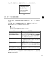
5.2 カードの設定変更
メニューから「Configuration Settings」を選択すると、更にメニューが表示さ
れます。
ここでは、カードの各種設定を参照したり、変更することができます。
表示されるメニューとその動作を下表に示します。
ポイント
通常は設定内容は変更せずに使用してください。
メニュー
動作概要
Host Adapter Settings
カードの動作設定を行います。
Selectable Boot Settings
ファイバーチャネルに接続されている装置か
らOSを起動する際に、起動する装置を選択し
ます。本製品では使用しません。
Restore Default Settings
カードの設定を初期化します。本処理を行う
と、各種設定が出荷時から変わってしまうた
め、実行しないでください。
Raw Nvram Data
各種設定を記憶しているNVRAMの内容を16
進数で表示します。設定内容は変更できませ
ん。
Advanced Adapter Settings
「Host Adapter Settings」以外の詳細な設定を
Extended Firmware Settings
行います。
「Host Adapter Settings」を実行すると以下に示す項目が表示され、設定を変
更することができます。
7
■ Host Adapter BIOS
サーバのブート時に ROM BIOS を使用するか否かを選択します。
初期状態では Disabled になっています。このとき、ROM BIOSが無効にな
り、アッパーメモリ領域が空きます。通常は Disabled にして使用してくださ
い。
■ Frame Size
本設定は、本製品がサポートする最大フレーム長を指定します。
初期値は 2048 になっています。
■ Loop Reset Delay
ファイバーチャネルインタフェースをリセットした後、動作状態にするまで
の待ち時間を秒数で指定します。
初期値は 5秒 になっています。
■ Adapter Hard ID
ファイバーチャネルに接続されるすべての装置にはIDが付けられます。本設
定を Enabled にしておくと、本製品のIDを、次に説明する Hard Loop ID で指
定した値にすることができます。
ただし、IDが他の装置と重複する場合には指定した値にならないこともあり
ます。
本設定の初期状態は Disabled になっています。
■ Hard Loop ID
Adapter Hard IDが Enabled になっているとき、IDが本設定で指定した値にな
ります。
初期値は 0 になっています。
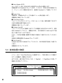
5.3 接続装置の確認
メニューから「Scan Fibre Devices」を選択すると、下図の例のように接続さ
れている装置が一覧表示されます。
全てのIDを一度に表示できないため、[PageUp]、[PageDown]を使って
画面を切り替えてください。
Scan Fibre Channel Loop
ID
0
1
2
3
Vendor
Product
Rev Node Name
Port ID
FUJITSU GR720
1113 200000000EDA0050 0000EF
QLogic
QLA22xx Adapter
210000E08B0214D0 0000E8
No device present
No device present
図4
8
5.4 接続装置の操作
メニューから「Fibre Disk Utility」を選択すると、接続されている装置が一覧
表示されます。
その画面から装置を選択して、ローレベルフォーマットまたはベリファイを
行うことができます。
ポイント
ローレベルフォーマットを実行すると、データはすべて消去されます。
誤って実行しないよう注意してください。
J
5.5 アダプタの選択
本製品が2枚以上搭載されているとき、Fast! UTILで使用するアダプタを選択
します。
「Select Host Adapter」を選択すると、下記のような画面が表示されます。
カーソルキーで、Fast! UTILを使用するカードを選択し、[ENTER]キーを
押してください。
Select Host Adapter
Adapter Type
I/O Address
QLA2xxx
3400
QLA2xxx
3800
図5
5.6 Fast! UTILの終了
「Exit Fast!UTIL」を選択すると、下記のメニューが表示されます。「Reboot
System」を選択すると Fast! UTILを終了し、サーバがリブートします。
「Return to Fast!UTIL」を選択するとFast!UTILのメニュー画面に戻ります。
Reboot System
Return to Fast!UTIL
図6
9
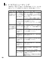
6 トラブルシューティング
本製品が正しく動作しない場合は、下記の項目を確認してください。各々の処
置を行ってもトラブルが解消できない場合には、保守員に連絡してください。
現
象
確認項目
処
置
本 製 品 ( カ ー サーバ起動時に 表示されない場合は、サーバの電源を
ド)がサーバか ページ6の図1の 切り、カバーを開けて、 カードがPCIス
ら認識されない メッセージが表 ロットに確実に差し込まれているか確
示されますか
認してください。
→「2. サーバ本体への搭載」を参照
ドライバが正しく ドライバが正しくインストールされて
インストールされ いるか確認してください。
ていますか(ペー →「4. ドライバのインストール」を参照
ジ4,5参照)
ファイバーチャ
ネルに接続され
ている装置が認
識できない
接続装置の電源 先に接続装置の電源を入れ、装置が起
が入っています 動した後で、サーバ本体の電源を入れ
てください。
か
ケーブルは正し コネクタが奥までしっかり差し込まれ
く接続されてい ているか確認してください。
ますか
接続装置は正し 装置の取扱説明書に従い、設定を確認
く設定されてい してください。
ますか
動作がおかしい ケーブルは正し コネクタが奥までしっかり差し込まれ
く接続されてい ているか確認してください。
ますか
接続装置は正し 装置の取扱説明書に従い、設定を確認
く設定されてい してください。
ますか
カードの設定は Fast! UTILを起動し、設定を確認してく
正しいですか
ださい。
→「5.ユーティリティ」を参照
サーバ本体の設定 サーバ本体の取扱説明書に従い、設定
は正しいですか を確認してください。
特にPCIスロットの位置やIRQの設定を
確認して下さい。
10
J
11
Introduction
Thank you for purchasing the Fujitsu fibre channel card PG-FC102 ("the Card").
Before using the card, read this user's guide carefully so that you can use it correctly.
January, 2001
Making sure of the contents of the package
Before using the card, make sure that the package contains all the items listed below.
If any item is missing in the package, please contact the Fujitsu sales representative in
charge.
●Fibre channel card
●User's guide (this manual)
●Floppy disk
This card is a Class 1 laser product.
QLogic is a trademark of Qlogic Inc.
Windows NT and Windows 2000 are trademark of Microsoft Corporation U.S.A., which has been registered in the United Status and other countries.
The product names referred to in this manual are trademarks or registered trademarks of their respective
manufacturers.
The products referred to in this manual are properties of their respective manufacturers.
All Rights Reserved, Copyright© FUJITSU LIMITED 2001
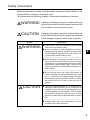
Safety instructions
Before using the card, carefully read these safety instructions and the manuals of the
relating devices so that you can properly use it.
This manual uses the following symbols to show safety precautions to be taken.
WARNING
Handling the product incorrectly without observing
the instructions that follow this symbol may cause the
risk of death or serious injury to persons.
CAUTION
Handling the product incorrectly without observing
the instructions that follow this symbol may cause the
risk of damage to property and/or injury to persons.
Symbol
WARNING
CAUTION
Description
■ Never modify the card, otherwise the card might
cause a fire or an electric shock.
■ When it thunders in your neighborhood, always
unplug the power cable of the server from the outlet
and disconnect all cables from this card. Failure to do
so might cause system failure or a fire.
----------------------------------------------------------------------■ Before loading or removing the card in or from a
server, be sure to turn off the server and all devices
connected to it, and then unplug their power cables
from the wall outlet for safety's sake. Failure to do so
might cause the risk of system failure, smoking, or an
electric shock.
----------------------------------------------------------------------■ Before moving the server, always disconnect all
cables (including the cables connected to the card)
from it. Failure to do so might damage the cables,
thus resulting in a fire or an electric shock, or causing
the server to fall over or down, doing an injury to
persons.
E
■ The card is a precision device. So avoid using or
keeping it under extremely severe conditions, for
example, in a very hot, very cold, or damp place, or in
a location exposed to direct sunlight. Also, be careful
not to bend or damage the card, nor to give a strong
impact to it, otherwise it might break down or cause a
fire.
----------------------------------------------------------------------■ When the card is not in use, always keep it in its case
to protect it from static electricity.
i
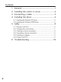
Contents
1
2
3
4
General ........................................................ 1
Installing the card in a server ....................... 2
Connecting a cable ...................................... 3
Installing the driver ....................................... 4
4.1 Installing the Windows NT driver ......................................... 4
4.2 Installing the Windows 2000 driver ...................................... 5
5 Utility ............................................................ 6
5.1
5.2
5.3
5.4
5.5
5.6
Starting Fast! UTIL ............................................................... 6
Changing the card settings .................................................. 7
Checking a device connected .............................................. 8
Formatting a device connected ............................................ 9
Selecting an adapter ............................................................ 9
Exiting Fast! UTIL ................................................................ 9
6 Troubleshooting ......................................... 10
ii
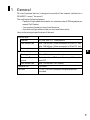
1 General
This card (optional device) is designed to provide a fibre channel interface for a
PRIMERGY server ("the server")
The card has the following features:
・ Capable of high-speed data transfer at a maximum rate of 200 megabytes per
second (Full Duplex).
・ You can place the device away from the server.
・ Uses thin and light cables so that you can install them easily.
Here are the principal specifications of the card.
Host bus type
Interface
PCI bus, Rev. 2.2 64bit/66MHz
Data transfer rate
Max. 528 MB/sec. (When mounted in a 64-bit PCI slot)
Max. 264 MB/sec. (When mounted in a 32-bit PCI slot)
Data transfer system
Bus master DMA (three channels)
E
Fibre channel type
Topology
Fibric/FC-AL (Arbitrated Loop)
Connector/Transter
system
Optical interface, SC Duplex Connector, Multi-mode,
non-OFC
Data transfer rate
Max. 200 MB/sec (Full Duplex)
Controller LSI
ISP2200A
Card size
17.78 × 10.67 cm (connector and protrusions not
included)
1
2 Installing the card in a server
WARNING
Before installing or removing the fibre channel card in
or from a server, always turn off the server and its
peripheral devices, and then disconnect their power
cables from the wall outlet. Failure to do so might cause
you to get an electric shock.
Follow the procedure below to install the card in a server.
For the procedure of installing expansion cards, including this card, in a server, refer
also to the instruction manual for the server.
1) Turn off the server and its peripheral devices, and then disconnect their power
cables from the wall outlet.
2) Remove the cover from the server.
3) Remove the bracket which blocks the PCI slot into which you want to insert the
card.
4) Insert the card into the PCI slot. At that time, push in the card as far as it will go
so that its terminal fits securely in the PCI slot.
5) Fix the card bracket firmly to the server.
CAUTION
Be sure to fix the card firmly. If the card is not fixed
securely, it might slip out of place at the time of
engagement or disengagement of the cable.
6) Attach the cover to the server.
7) Set IRQ and other settings referring to the instruction manual for the server.
2
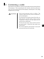
3 Connecting a cable
Each connector of the cable has a protrusion which determines the inserting direction
of the connector. When connecting the cable, therefore, check this protrusion to
make sure of the inserting direction of the connector, and then push it in the mating
connector as far as it will go.
CAUTION
・ Push in each connector as far as it will go. The
connector might cause the system to malfunction, if
not inserted properly.
・ Do not put any heavy object on top of the cable, nor
bend it sharply. Install the cables to shat no tension
is applied to it. Otherwise, the cable might cause the
system to fail or malfunction.
・ To disconnect the cable, always pull the connector
but not the cable. Pulling the cable might cause
E
system failure.
・ This card uses light for communication. So be careful
not to make the ends of its cable dirty.
3
4. Installing the driver
You can install the driver in the same way as ordinary SCSI cards.
Follow the procedure below to install the driver.
4.1 Installing the Windows NT driver
1) Choose "SCSI Adapters" from the Control Panel. A dialog box appears,
displaying a list of SCSI adapters.
2) Click on the "Drivers" tab to open the "Driver List".
3) Click on the "Add" button, then click on "Have Disk" button in the dialog box
currently displayed.
4) Insert the floppy disk marked with "PG-FC102 Drivers Disk" into the floppy disk
drive, type "A:¥NT" in the "Copy Manufacturer's files from" text box, and then
click on "OK".
5) "QLogic QLA2200 PCI Fibre Channel Adapter" is displayed on screen. Choose
it and click on "OK". Now the driver has been installed successfully. Reboot
Windows NT to enable the driver program.
Note
Click the Start button on the Taskbar. And select "Settings" to "Control Panel".
Double-click "SCSI Adapters" and click "Drivers" tab. When the driver is
installed, "QLogic QLA2200 PCI Fibre Channel Adapter" is displayed on the
window.
4
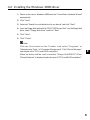
4.2 Installing the Windows 2000 driver
1) Power on the server. Windows 2000 starts the "Found New Hardware Wizard"
automatically.
2) Click "Next".
3) Select the "Search for a suitable driver for my device" and click "Next".
4) Insert the floppy disk marked with "PG-FC102 Drivers Disk" into the floppy disk
drive, check "Floppy disk drives" and click "Next".
5) Click "Next".
6) Click "Finish".
Note
Click the Start button on the Taskbar. And select "Programs" to
"Administrative Tools " to "Computer Management". Click "Device Manager"
E
and double-click "SCSI and RAID controllers".
When the driver and the card is installed, "QLogic QLA2200 PCI Fibre
Channel Adapter" is displayed under the tree of "SCSI and RAID controllers".
5
5 Utility
The card has an on-board ROM which stores the utility program "Fast! UTIL". Using
this utility program, you can set up the card, check and diagnose the device
connected.
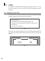
5.1 Starting Fast! UTIL
To start Fast! UTIL, press the Alt and Q keys at the same time while the following
message is displayed on screen at the boot-up of the server.
QLogic Corporation
QLA2200 PCI Fibre Channel ROM BIOS Version 1.54
Copyright (C) QLogic Corporation 1993-2000. All rights reserved
www.qlc.com
Press <Alt+Q> for Fast!UTIL
Fig. 1
When two or more cards are mounted in a server, the following window appears first.
Using arrow keys, select the card for which you want to use Fast! UTIL, then press the
Enter key.
Select Host Adapter
Adapter Type
I/O Address
QLA2xxx
QLA2xxx
3400
3800
Fig. 2
6
After Fast! UTIL has started up, the following menu appears on screen.
Configuration Settings
Scan Fibre Devices
Fibre Disk Utility
Select Host Adapter
Exit Fast!UTIL
Fig. 3
5.2 Changing the card settings
Selecting "Configuration Settings" from the menu causes another menu to appear.
With the options in this menu, you can check and change the card settings.
Here are the available options and their functions.
E
Note
It is advisable not to change the card settings in ordinary cases.
Functions
Options
Host Adapter Settings
Allows you to set the operating conditions of the
card.
Selectable Boot Settings
Allows you to select the startup device if you
want to boot up the system from the device
connected to the fibre channel. This option
cannot be used with the supplied card.
Restore Default Settings
Initializes the card. Do not execute this, because
the settings change.
Raw Nvram Data
Displays the settings recorded on the NVRAM in
hexadecimal notation. The settings cannot be
changed.
Advanced Adapter Settings
Extended Firmware Settings
Allows you to set the operation conditions of the
card.
If you select "Host Adapter Settings", the items listed below are displayed so that you
can change the settings.
7
■ Host Adapter BIOS
You can make a selection between the use and disuse of the ROM BIOS at the bootup of the system.
The ROM BIOS is set to "Disabled" by default, in which state the ROM BIOS is
disabled and the upper memory area is unallocated. Under normal conditions, use the
card with the ROM BIOS disabled.
■ Frame size
You can designate the maximum frame size that the card supports.
The frame size is set to 2048 by default.
■ Loop Reset Delay
You can designate in seconds the time elapsed before the fibre channel interface
becomes ready for use after the reset.
The delay is set to 5 seconds by default.
■ Adapter Hard ID
An ID number is assigned to every device connected to the fibre channel. If this
option is set to "enabled", the ID number of this card can be changed to that
designated in the Hard Loop ID described below.
However, if the ID number is already used for another device, then the ID number
may be rejected and changed to another.
This option is set to "Disabled" by default.
■ Hard Loop ID
If Adapter Hard ID is set to "Enabled", the same ID number as set in this menu is
assigned.
The default value is 0.
5.3 Checking a device connected
If you select "Scan Fibre Devices" from the menu, a window appears, displaying a list
of the devices connected.
Scan Fibre Channel Loop
ID
0
1
2
3
Vendor
Product
Rev Node Name
Port ID
FUJITSU GR720
1113 200000000EDA0050 0000EF
QLogic
QLA22xx Adapter
210000E08B0214D0 0000E8
No device present
No device present
Fig. 4
8
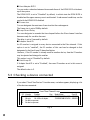
5.4 Formatting a device connected
If you select "Fibre Disk Utility" from the menu, a window appears, displaying a list
of the devices connected.
In this window, you can select the device that you want to low-level format or verify.
Note
The low-level formatting erases all data stored in it.
So be careful not to execute this command by mistake.
5.5 Selecting an adapter
If two or more cards are installed in the server, you need to select an adapter, using
Fast! UTIL.
Selecting "Select Host Adapter" causes the following window to appear.
Using arrow keys, select the card for which you want to use Fast! UTIL, then press
E
Enter key.
Select Host Adapter
Adapter Type
I/O Address
QLA2xxx
QLA2xxx
3400
3800
Fig. 5
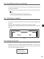
5.6 Exiting Fast! UTIL
Selecting "Exit Fast! UTIL" causes the following menu to appear. To exit Fast! UTIL
and reboot the server, select "Reboot System" from this menu; to return to the Fast!
UTIL menu, select "Return to Fast! UTIL".
Reboot System
Return to Fast!UTIL
Fig. 6
9
6 Troubleshooting
Check the applicable items listed below in case the card does not operate correctly. If
you cannot resolve the trouble even though you have taken measures as prescribed,
contact the service person.
Symptoms
Remedies
Items to be checked
The card is not
Is the message of If the message is not displayed, turn off the
recognized by the Fig. 1 at page 6 at server, remove the cover, and check
server.
the boot-up of the whether the card is mounted properly in a
PCI slot.
server?
→ Refer to "2. Installing the card in a
server".
Is the device
supplied with
power?
The device
connected to the
Is the device
supplied with
fibre channel is
not recognized.
power?
Check whether the driver is correctly
installed.
→ Refer to "4. Installing the driver".
Turn on the device first, and then turn on
the server after the device has started up.
Are all cables
Check whether all connectors are engaged
connected
correctly?
securely.
Is the connected
device set up
Check the settings against the instruction
manual for the device.
correctly?
The server does
Are all cables
Check whether all connectors are engaged
not operate
properly.
connected
correctly?
securely.
Is the connected
device set up
Check the settings against the instruction
manual for the device.
correctly?
10
Is the card set up
Check the settings, using Fast! UTIL.
correctly?
→ Refer to "5. Utility".
Is the server set
up correctly?
Check the settings against the instruction
manual for the server.
MEMO
E
11
MEMO
12
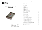
ファイバーチャネルカード
(PG-FC102)
取扱説明書
Fibre Channel Card
(PG-FC102)
User's Guide
P3FY-1280-01-00
発 行 日 2001年1月
Publication date: January 2001
発行責任 富士通株式会社
Publisher: Fujitsu Limited
Printed in Japan
●本書の内容は、改善のため事前連絡なしに変更することがあります。
●本書に記載されたデータの使用に起因する第三者の特許権およびその他の
権利の侵害については、当社はその責を負いません。
●無断転載を禁じます。
●落丁、乱丁本は、お取り替えいたします。
●Information provided in this document is subject to change without prior notice.
●Fujitsu does not assume any liability for infringement of third party patents and any
other rights caused by abuse of information provided in this document.
●Transcription without prior permission is prohibited.
●Any manual which has missing pages or which is incorrectly collated will be replaced.
ヤ 0101-1
このマニュアルは再生紙を使用しています。