1
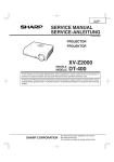
EIP-3500
SERVICE MANUAL
S04A7XG-MB70X
TM
DLP PROJECTOR
MODEL
EIP-3500
In the interests of user-safety (Required by safety regulations in some countries) the set should be restored to its original condition and only parts identical to those specified should be used.
This document has been published to be used for
after sales service only.
The contents are subject to change without notice.
EIP-3500
CONTENTS
Page
Page
• SPECIFICATIONS ............................................ 3
• IMPORTANT SERVICE SAFETY
NOTES .............................................................. 4
• NOTE TO SERVICE PERSONNEL .................. 6
• OPERATION MANUAL ................................... 10
• DIMENSIONS ................................................. 16
• REMOVING OF MAJOR PARTS .................... 17
• RESETTING THE TOTAL LAMP TIMER ......... 22
• THE OPTICAL UNIT OUTLINE ...................... 24
• ELECTRICAL ADJUSTMENT ......................... 26
• TROUBLE SHOOTING TABLE ....................... 34
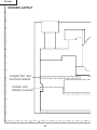
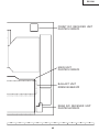
• CHASSIS LAYOUT .......................................... 48
•
•
•
•
•
BLOCK DIAGRAM .......................................... 50
OVERALL WIRING DIAGRAM ........................ 52
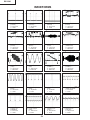
WAVEFORMS ................................................. 54
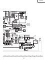
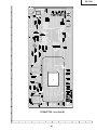
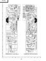
PRINTED WIRING BOARD ASSEMBLIES ..... 55
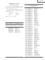
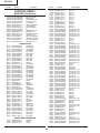
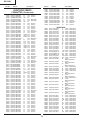
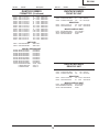
PARTS LIST
Ë ELECTRICAL PARTS ................................. 63
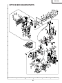
Ë CABINET AND MECHANICAL PARTS ...... 78
Ë ACCESSORIES PARTS ............................. 82
Ë PACKING PARTS ....................................... 82
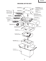
• PACKING OF THE SET .................................. 83
2
EIP-3500
SPECIFICATIONS
Product type DLPTM Projector
Model EIP-3500
Video system NTSC3.58/NTSC4.43/PAL/PAL-M/PAL-N/PAL-60/SECAM/
DTV480I/DTV480P/DTV540P/DTV576I/DTV576P/DTV720P/DTV1035I/DTV1080I
Display method Single Chip Digital Micromirror DeviceTM (DMDTM) by Texas Instruments
DMD panel Panel size: 0.7"
No. of dots: 786,432 dots (1,024 [H] × 768 [V])
Lens 1.5 × electric zoom/focus lens, F2.0 – 2.5, f = 21.3 – 31.6 mm
Projection lamp 275 W DC lamp
Component input (INPUT 1/2)/ 15-pin mini D-sub connector
output (OUTPUT) signal Y: 1.0 Vp-p, sync negative, 75 Ω terminated
PB: 0.7 Vp-p, 75 Ω terminated
PR: 0.7 Vp-p, 75 Ω terminated
Horizontal resolution 750 TV lines (DTV720P)
Computer RGB input (INPUT 1/2)/ 15-pin mini D-sub connector
output (OUTPUT) signal RGB separate/sync on green type analog input: 0 – 0.7 Vp-p, positive, 75 Ω terminated
HORIZONTAL SYNC. SIGNAL: TTL level (positive/negative)
VERTICAL SYNC. SIGNAL: Same as above
Video input signal RCA connector: VIDEO, composite video, 1.0 Vp-p, sync negative, 75 Ω
(INPUT 3) terminated
S-video input signal 4-pin mini DIN connector
(INPUT 4) Y (luminance signal): 1.0 Vp-p, sync negative, 75 Ω terminated
C (chrominance signal): Burst 0.286 Vp-p, 75 Ω terminated
Audio input signal Ø 3.5 mm minijack: AUDIO, 0.5 Vrms, more than 22 k Ω (stereo)
USB terminal 4-pin B-type USB female connector
RS-232C terminal 9-pin mini DIN connector
LAN terminal 8-pin RJ-45 modular connector
Pixel clock 12 – 108 MHz
Vertical frequency 43 – 85 Hz
Horizontal frequency 15 – 70 kHz
Audio output 2.0 W (monaural)
Speaker system 4.0 cm × 2.85 cm oval × 1
Rated voltage AC 100 – 240 V
Input current 3.9 A
Rated frequency 50/60 Hz
Power consumption 370 W (Standard mode)/320 W (Eco mode) with AC 100 V
350 W (Standard mode)/300 W (Eco mode) with AC 240 V
Power consumption (standby) 6 W (AC 100 V) – 8 W (AC 240 V)
Heat dissipation 1,390 BTU/hour (Standard mode)/1,200 BTU/hour (Eco mode) with AC 100 V
1,315 BTU/hour (Standard mode)/1,130 BTU/hour (Eco mode) with AC 240 V
Operating temperature 41°F to 104°F (+5°C to +40°C)
Storage temperature – 4°F to 140°F ( – 20°C to +60°C)
Cabinet Plastic
I/R carrier frequency 38 kHz
Dimensions (approx.) 12 7/32" × 3 33/64" × 11 7/64" (310 (W) × 89 (H) × 282 (D) mm) (main body only)
12 7/32" × 4 7/64" × 11 5/16" (310 (W) × 104 (H) × 287 (D) mm) (including adjustment foot
and projecting parts)
Weight (approx.) 9.3 lbs. (4.2 kg)
Replacement parts Lamp unit (Lamp/cage module) (AH-35001), Remote control (RRMCGA371WJSA), Power
cord for U.S., Canada, etc. (QACCDA010WJPZ), Power cord for Europe, except U.K.
(QACCVA011WJPZ), RGB cable (QCNWGA045WJPZ), USB cable (QCNWGA014WJPZ),
Storage case (GCASNA018WJSA), Lens cap (PCAPHA021WJSA), 3 RCA to 15-pin D-sub
cable (QCNWGA043WJPZ), DIN-D-sub RS-232C adaptor (QCNWGA015WJPZ), Technical
reference CD-ROM (UDSKAA060WJZZ), QUICK GUIDE (TINS-B723WJZZ), Operation
manual (TINS-B671WJZZ (English), TINS-B672WJZZ (French), TINS-B673WJZZ (Spanish),
TINS-B674WJZZ (Italian), TINS-B675WJZZ (German), TINS-B676WJZZ (Portuguese))
As a part of policy of continuous improvement, EIKI reserves the right to make design
and specification changes for product improvement without prior notice. The performance
specification figures indicated are nominal values of production units. There may be some
deviations from these values in individual units.
3
EIP-3500
IMPORTANT SERVICE SAFETY NOTES (for USA)
Ë Service work should be performed only by qualified service technicians who are
thoroughly familiar with all safety checks and servicing guidelines as follows:
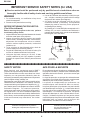
» Use an AC voltmeter with sensitivity of 5000 ohm per
volt., or higher, sensitivity to measure the AC voltage
drop across the resistor (See Diagram).
» All checks must be repeated with the AC plug
connection reversed. (If necessary, a non-polarized
adapter plug must be used only for the purpose of
completing these checks.)
Any reading of 0.3 volts RMS (this corresponds to 0.2
milliamp. AC.) or more is excessive and indicates a
potential shock hazard which must be corrected before
returning the unit to the owner.
WARNING
1. For continued safety, no modification of any circuit
should be attempted.
2. Disconnect AC power before servicing.
BEFORE RETURNING THE PROJECTOR:
(Fire & Shock Hazard)
Before returning the projector to the user, perform
the following safety checks:
1. Inspect lead wires are not pinched between the chassis
and other metal parts of the projector.
2. Inspect all protective devices such as non-metallic
control knobs, insulating materials, cabinet backs,
adjustment and compartment covers or shields,
isolation resistor-capacity networks, mechanical
insulators, etc.
3. To be sure that no shock hazard exists, check for
current leakage in the following manner:
» Plug the AC cord directly into a 120-volt AC outlet, (Do
not use an isolation transformer for this test).
» Using two clip leads, connect a 1.5k ohm, 10 watt
resistor paralleled by a 0.15µF capacitor in parallel
between all exposed metal cabinet parts and earth
ground.
DVM
AC SCALE
1.5k ohm
10W
0.15 µF
TEST PROBE
TO EXPOSED
METAL PARTS
CONNECT TO
KNOWN EARTH
GROUND
12345678901234567890123456789012123456789012345678901234567890121234567890123456789012345678901212
12345678901234567890123456789012123456789012345678901234567890121234567890123456789012345678901212
12345678901234567890123456789012123456789012345678901234567890121234567890123456789012345678901212
SAFETY NOTICE
AVIS POUR LA SECURITE
Many electrical and mechanical parts in DMD™
Projector have special safety-related characteristics.
These characteristics are often not evident from visual
inspection, nor can protection afforded by them be
necessarily increased by using replacement components
rated for higher voltage, wattage, etc.
Replacement parts which have these special safety
characteristics are identified in this manual; electrical
components having such features are identified by “å”
and shaded areas in the Replacement Parts Lists and
Schematic Diagrams. For continued protection,
replacement parts must be identical to those used in
the original circuit. The use of a substitute replacement
parts which do not have the same safety characteristics
as the factory recommended replacement parts shown
in this service manual, may create shock, fire or other
hazards.
De nombreuses pièces, électriques et mécaniques, dans
les projecteur à DMD™ présentent des caractéristiques
spéciales relatives à la sécurité, qui ne sont souvent pas
évidentes à vue.
Le degré de protection ne peut pas être nécessairement
augmentée en utilisant des pièces de remplacement
étalonnées pour haute tension, puissance, etc.
Les pièces de remplacement qui présentent ces
caractéristiques sont identifiées dans ce manuel;
les pièces électriques qui présentent ces particularités
sont identifiées par la marque “å” et hachurées dans la
liste des pièces de remplacement et les diagrammes
schématiques. Pour assurer la protection, ces pièces
doivent être identiques à celles utilisées dans le circuit
d’origine. L’utilisation de pièces qui n’ont pas les mêmes
caractéristiques que les pièces recommandées par l’usine,
indiquées dans ce manuel, peut provoquer des
électrocutions, incendies ou autres accidents.
WARNING: The bimetallic component has the primary
conductive side exposed. Be very careful in
handling this component when the power is on.
AVERTISSEMENT: La composante bimétallique dispose du
conducteur primaire dénudé. Faire attention
lors de la manipulation de cette
composante sous tension.
12345678901234567890123456789012123456789012345678901234567890121234567890123456789012345678901212
12345678901234567890123456789012123456789012345678901234567890121234567890123456789012345678901212
12345678901234567890123456789012123456789012345678901234567890121234567890123456789012345678901212
4
EIP-3500
PRECAUTIONS A PRENDRE LORS DE LA REPARATION
Ë
Ne peut effectuer la réparation qu' un technicien spécialisé qui s'est parfaitement
accoutumé à toute vérification de sécurité et aux conseils suivants.
AVERTISSEMENT
conduite électrique ou une prise de terre branchée à la
terre.
• Utiliser un voltmètre CA d'une sensibilité d'au moins
5000Ω/V pour mesurer la chute de tension en travers
de la résistance.
• Toucher avec la sonde d'essai les pièces métalliques
exposées qui présentent une voie de retour au châssis
(antenne, coffret métallique, tête des vis, arbres de
commande et des boutons, écusson, etc.) et mesurer la
chute de tension CA en-travers de la résistance. Toutes
les vérifications doivent être refaites après avoir inversé
la fiche du cordon d'alimentation. (Si nécessaire, une
prise d'adpatation non polarisée peut être utilisée dans
le but de terminer ces vérifications.)
Tous les courants mesurés ne doivent pas dépasser 0.5
mA.
Dans le cas contraire, il y a une possibilité de choc
électrique qui doit être supprimée avant de rendre le
récepteur au client.
1. N'entreprendre aucune modification de tout circuit.
C'est dangereux.
2. Débrancher le récepteur avant toute réparation.
PRECAUTION: POUR LA
PROTECTION CONTINUE CONTRE
LES RISQUES D'INCENDIE,
REMPLACER LE FUSIBLE
CÔTÉ LCD : F701 (6.3A, AC250V)
VERIFICATIONS CONTRE L'INCEN-DIE ET
LE CHOC ELECTRIQUE
Avant de rendre le récepteur à l'utilisateur, effectuer
les vérifications suivantes.
1. Inspecter tous les faisceaux de câbles pour s'assurer
que les fils ne soient pas pincés ou qu'un outil ne soit
pas placé entre le châssis et les autres pièces
métalliques du récepteur.
2. Inspecter tous les dispositifs de protection comme les
boutons de commande non-métalliques, les isolants, le
dos du coffret, les couvercles ou blindages de réglage
et de compartiment, les réseaux de résistance-capacité,
les isolateurs mécaniques, etc.
3. S'assurer qu'il n'y ait pas de danger d'électrocution en
vérifiant la fuite de courant, de la facon suivante:
• Brancher le cordon d'alimentation directem-ent à une
prise de courant de 110-240V. (Ne pas utiliser de
transformateur d'isolation pour cet essai).
• A l'aide de deux fils à pinces, brancher une résistance
de 1.5 kΩ 10 watts en parallèle avec un condensateur
de 0.15µF en série avec toutes les pièces métalliques
exposées du coffret et une terre connue comme une
DVM
ECHELLE CA
1.5k ohm
10W
0.15 µF
SONDE D'ESSAI
AUX PIECES
METALLIQUES
EXPOSEES
BRANCHER A UNE
TERRE CONNUE
12345678901234567890123456789012123456789012345678901234567890121234567890123456789012345678901212
12345678901234567890123456789012123456789012345678901234567890121234567890123456789012345678901212
12345678901234567890123456789012123456789012345678901234567890121234567890123456789012345678901212
AVIS POUR LA SECURITE
De nombreuses pièces, électriques et mécaniques, dans les téléviseur ACL présentent des caractéristiques spéciales
relatives à la sécurité, qui ne sont souvent pas évidentes à vue. Le degré de protection ne peut pas être nécessairement
augmentée en utilisant des pièces de remplacement étalonnées pour haute tension, puissance, etc.
Les pièces de remplacement qui présentent ces caractéristiques sont identifiées dans ce manuel; les pièces électriques
qui présentent ces particularités sont identifiées par la marque " å " et hachurées dans la liste des pièces de
remplacement et les diagrammes schématiques.
Pour assurer la protection, ces pièces doivent être identiques à celles utilisées dans le circuit d'origine. L'utilisation
de pièces qui n'ont pas les mêmes caractéristiques que les pièces recommandées par l'usine, indiquées dans ce
manuel, peut provoquer des électrocutions, incendies, radiations X ou autres accidents.
12345678901234567890123456789012123456789012345678901234567890121234567890123456789012345678901212
12345678901234567890123456789012123456789012345678901234567890121234567890123456789012345678901212
12345678901234567890123456789012123456789012345678901234567890121234567890123456789012345678901212
12345678901234567890123456789012123456789012345678901234567890121234567890123456789012345678901212
5
EIP-3500
NOTE TO SERVICE
NOTE POUR LE PERSONNEL
PERSONNEL
D’ENTRETIEN
123456789012345678901234567890121234567890123456 123456789012345678901234567890121234567890123456
123456789012345678901234567890121234567890123456
123456789012345678901234567890121234567890123456
UV-RADIATION PRECAUTION
123456789012345678901234567890121234567890123456
123456789012345678901234567890121234567890123456
PRECAUTION POUR LES RADIATIONS UV
123456789012345678901234567890121234567890123456
123456789012345678901234567890121234567890123456
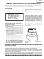
The light source, UHP lamp, in the LCD projector
emits small amounts of UV-Radiation.
La source de lumière, la lampe UHP, dans le projecteur
LCD émet de petites quantités de radiation UV.
AVOID DIRECT EYE AND SKIN EXPOSURE.
EVITEZ TOUTE EXPOSITION DIRECTE DES
YEUX ET DE LA PEAU.
To ensure safety please adhere to the following:
Pour votre sécurité, nous vous prions de respecter
les points suivants:
1. Toujours porter des lunettes de soleil lors d’un entretien
du projecteur
avec la lampe allumée
et le haut du coffret retiré.
1. Be sure to wear sun-glasses when servicing the
projector with the lamp
turned “on” and the top
enclosure removed.
2. Ne pas faire fonctionner la lampe à l’extérieur du boîtier
de lampe.
2. Do not operate the lamp outside of the lamp housing.
3. Ne pas faire fonctionner plus de 2 heures avec le coffret
retiré.
3. Do not operate for more than 2 hours with the enclosure
removed.
Précautions pour les radiations UV
et la lampe moyenne pression
UV-Radiation and Medium Pressure
Lamp Precautions
1. Toujours débrancher la fiche AC lors du remplacement
de la lampe.
2. Laisser l’unité refroidir pendant une heure avant de
procéder à l’entretien.
3. Ne remplacer qu’avec une lampe du même type. Type
AH-35001, caractéristique 275W.
4. La lampe émet de petites quantités de radiation UVéviter tout contact direct avec les yeux.
5. La lampe moyenne pression implique un risque
d’explosion. Toujours suivre les instructions
d’installation décrites ci-dessous et manipuler la lampe
avec soin.
1. Be sure to disconnect the AC plug when replacing the
lamp.
2. Allow one hour for the unit to cool down before
servicing.
3. Replace only with same type lamp. Type AH-35001
rated 275W.
4. The lamp emits small amounts of UV-Radiation, avoid
direct-eye contact.
5. The medium pressure lamp involves a risk of explosion.
Be sure to follow installation instructions described
below and handle the lamp with care.
6
EIP-3500
123456789012345678901234567890121234567890123456
123456789012345678901234567890121234567890123456
123456789012345678901234567890121234567890123456
123456789012345678901234567890121234567890123456
123456789012345678901234567890121234567890123456
123456789012345678901234567890121234567890123456
UV-RADIATION PRECAUTION (Continued)
123456789012345678901234567890121234567890123456
123456789012345678901234567890121234567890123456
123456789012345678901234567890121234567890123456
PRECAUTION POUR LES RADIATIONS UV (Suite)
123456789012345678901234567890121234567890123456
123456789012345678901234567890121234567890123456
123456789012345678901234567890121234567890123456
Lamp Replacement
Remplacement de la lampe
Note:
Remarque:
Since the lamp reaches a very high temperature during
units operation replacement of the lamp should be
done at least one hour after the power has been turned
off. (to allow the lamp to cool off.)
Installing the new lamp, make sure not to touch the
lamp (bulb) replace the lamp by holding its reflector
2.
[Use original replacement only.]
Comme la lampe devient très chaude pendant le
fonctionnement de l’unité, son remplacement ne doit
être effectué au moins une heure après avoir coupé
l’alimentation (pour permettre à la lampe de refroidir).
En installant la nouvelle lampe, s’assurer de ne pas
toucher la lampe (ampoule). Remplacer la lampe en
tenant son réflecteur 2.
[N’utiliser qu’un remplacement d’origine.]
1 Lampe
1 Lamp
2 Reflecteur
2 Reflector
DANGER ! –– Never turn the power on without the
lamp to avoid electric-shock or damage of the devices
since the stabilizer generates high voltages at its start.
DANGER ! –– Ne jamais mettre sous tension sans la
lampe pour éviter un choc électrique ou des
dommages des appareils car le stabilisateur génère
de hautes tensions à sa mise en route.
Since small amounts of UV-radiation are emitted
from an opening between the exhaust fans, it is recommended to place the cap of the optional lens on
the opening during servicing to avoid eye and skin
exposure.
Comme de petites quantités de radiation UV sont
émises par une ouverture entre les ventilateurs aspirants, il est recommandé de placer le capuchon de
l’optique optionnelle sur l’ouverture pendant l’entretien
pour éviter une exposition des yeux et la peau.
7
EIP-3500
WARNING:
High brightness light source, do not stare into the beam of light, or view directly. Be especially
careful that children do not stare directly in to the beam of light.
WARNING:
TO REDUCE THE RISK OF FIRE OR ELECTRIC SHOCK, DO NOT EXPOSE THIS UNIT TO
MOISTURE OR WET LOCATIONS.
CAUTION
The lighting flash with arrowhead within a
triangle is intended to tell the user that
parts inside the product are risk of electric
shock to persons.
RISK OF ELECTRIC SHOCK.
DO NOT REMOVE SCREWS
EXCEPT SPECIFIED USER
SERVICE SCREW.
CAUTION: TO REDUCE THE RISK OF ELECTRIC SHOCK,
DO NOT REMOVE CABINET.
NO USER-SERVICEABLE PARTS EXCEPT LAMP UNIT.
REFER SERVICING TO QUALIFIED SERVICE
PERSONNEL.
The exclamation point within a triangle is
intended to tell the user that important
operating and servicing instructions are in
the manual with the projector.
CAUTION
(POWER Unit)
6.3A 250V
For continued
protection against a
risk of fire, replace
only with same type
6.3A, AC250V fuse.
(F701)
12345678901234567890123456789012123456789012345678901234567890121234567890123456789012345678901212
12345678901234567890123456789012123456789012345678901234567890121234567890123456789012345678901212
AVERTISSEMENT: Source lumineuse de grande intensité. Ne pas fixer le faisceau lumineux ou le regarder
directement. Veiller particulièrement à éviter que les enfants ne fixent directement le
faisceau lumineux.
AVERTISSEMENT: AFIN D’EVITER TOUT RISQUE D’INCENDIE OU D’ELECTROCUTION, NE PAS PLACER
CET APPAREIL DANS UN ENDROIT HUMIDE OU MOUILLE.
ATTENTION
L’éclair terminé d’une flèche à l’intérieur
d’un triangle indique à l’utilisateur que les
pi‘eces se trouvant dans l’appareil sont
susceptibles de provoquer une décharge
électrique.
RISQUE
D’ÉLECTROCUTION. NE
PASR ETIRER LES VIS Á
L’EXCEPTION DE LA VIS DE
REPARATION UTILISATEUR
SPECIFIEES
Le point d’exclamation à l’intérieur d’un
triangle indique à l’utilisateur que les
instructions de fonctionnement et
d’entretien sont détaillées dans les
documents fournis avec le projecteur.
ATTENTION: POUR EVITER TOUT RISQUE
D’ELECTROCUTION, NE PAS RETIRER LE CAPOT.
AUCUNE DES PIECES INTERIEURES N’EST REPARABLE
PAR L’UTILISATEUR, A L’EXCEPTION DE L’UNITE DE
LAMPE. POUR TOUTE REPARATION, S’ADRESSER A UN
TECHNICIEN D’ENTRETIEN QUALIFIE.
PRECAUTION
(Unité de PUTSSANCE)
Pour une protection
continue contre un
risques d’incendie, ne
remplacer qu’avec un
fusible 6.3A,AC250V
6.3A 250V du même type.
(F701)
8
EIP-3500
Precautions for using lead-free solder
1 Employing lead-free solder
"PWBs" of this model employs lead-free solder. The LF symbol indicates lead-free solder, and is attached on the
PWBs and service manuals. The alphabetical character following LF shows the type of lead-free solder.
Example:
LFa
Indicates lead-free solder of tin, silver and copper.
2 Using lead-free wire solder
When fixing the PWB soldered with the lead-free solder, apply lead-free wire solder. Repairing with conventional
lead wire solder may cause damage or accident due to cracks.
As the melting point of lead-free solder (Sn-Ag-Cu) is higher than the lead wire solder by 40°C, we recommend you
to use a dedicated soldering bit, if you are not familiar with how to obtain lead-free wire solder or soldering bit,
contact our service station or service branch in your area.
3 Soldering
As the melting point of lead-free solder (Sn-Ag-Cu) is about 220°C which is higher than the conventional lead solder
by 40°C, and as it has poor solder wettability, you may be apt to keep the soldering bit in contact with the PWB for
extended period of time. However, since the land may be peeled off or the maximum heat-resistance temperature of
parts may be exceeded, remove the bit from the PWB as soon as you confirm the steady soldering condition.
Lead-free solder contains more tin, and the end of the soldering bit may be easily corroded. Make sure to turn on
and off the power of the bit as required.
If a different type of solder stays on the tip of the soldering bit, it is alloyed with lead-free solder. Clean the bit after
every use of it.
When the tip of the soldering bit is blackened during use, file it with steel wool or fine sandpaper.
Be careful when replacing parts with polarity indication on the PWB silk.
Lead-free wire solder for servicing
Part No.
ZHNDAi123250E
ZHNDAi126500E
ZHNDAi12801KE
★
J
J
J
Description
φ0.3mm
250g(1roll)
φ0.6mm
500g(1roll)
φ1.0mm
1kg(1roll)
9
Code
BL
BK
BM
EIP-3500
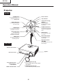
Operation Manual
Projector
Top View
POWER button
Power indicator
For turning the power on or
putting the projector into
standby mode.
Lamp indicator
Temperature warning
indicator
Volume buttons
KEYSTONE button
For entering the Keystone
Correction mode.
For adjusting the speaker
sound level.
ZOOM-FOCUS button
ENTER button
For adjusting the projected
image size or adjusting the
focus.
For setting items selected
or adjusted on the menu.
AUTO SYNC button
INPUT buttons
For automatically
adjusting images when
connected to a computer.
For switching input mode
1, 2, 3 or 4.
AUTO FOCUS button
MENU button
For adjusting the focus
automatically.
For displaying adjustment
and setting screens.
Adjustment buttons
('/"/\/|)
For selecting menu items and
other settings.
Front View
Remote control sensor
Speaker
Auto focus sensor
Front adjustment foot
(on the bottom of
the projector)
HEIGHT ADJUST button
Attaching the lens cap
Push the lens cap on until it clicks
into position.
Removing the lens cap
Pull the lens cap directly outward.
10
EIP-3500
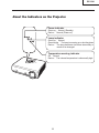
About the Indicators on the Projector
Power indicator
Green on ... Normal (Standby)
Red on ... Normal (Power on)
Lamp indicator
Green on ... Normal
Green blinks ... The lamp is warming up or shutting down.
Red on ... The lamp has been shut down abnormally or
needs to be changed.
Temperature warning indicator
Off ... Normal
Red on ... The internal temperature is abnormally high.
11
EIP-3500
Projector (Rear View)
Terminals
Refer to “INPUT/OUTPUT Terminals and Connectable Main Equipment” on
AUDIO OUTPUT terminal
INPUT 3 terminal
Audio output terminal of
equipment connected to the
AUDIO INPUT terminal.
Terminal for connecting
video equipment.
INPUT 4 terminal
Terminal for connecting
video equipment with an
S-video terminal.
OUTPUT (INPUT 1, 2) terminal
· Shared computer RGB and component
signals output terminal for INPUT 1 and 2.
· Terminal for connecting a monitor.
AUDIO INPUT 3, 4 terminal
Shared audio input terminal
for INPUT 3 and 4.
AUDIO INPUT 1, 2 terminal
Shared audio input terminal
for INPUT 1 and 2.
USB terminal
INPUT 2 terminal
RS-232C terminal
Terminal for computer RGB
and component signals.
Terminal for controlling
the projector using a computer.
INPUT 1 terminal
LAN terminal
Terminal for computer RGB
and component signals.
Terminal for controlling the
projector using a computer via
network.
Exhaust vent
The speed and pitch of
the cooling fan may
change during operation
in response to internal
temperature changes.
This is normal operation
and does not indicate a
malfunction.
Remote control sensor
Intake vent
Kensington Security
Standard connector
AC socket
Connect the supplied
Power cord.
Rear adjustment feet
Using the Kensington Lock
This projector has a Kensington Security Standard connector for use with a Kensington MicroSaver Security
System. Refer to the information that came with the system for instructions on how to use it to secure the
projector.
12
EIP-3500
Remote Control
POWER button
AUTO FOCUS button
For turning the power on or
putting the projector into
standby mode.
For adjusting the focus
automatically.
FOCUS buttons
For bringing the projected image
into focus.
ZOOM buttons
For adjusting the projected
image size.
IRIS button
For switching "HIGH BRIGHTNESS
MODE" or "HIGH CONTRAST MODE".
KEYSTONE button
MENU button
For entering the Keystone
Correction mode.
For displaying adjustment and
setting screens.
MOUSE/Adjustment button
('/"/\/|)
L-CLICK/ENTER button
For moving the computer cursor
when connecting the projector
USB terminal to the computer
with USB cable.
For selecting menu items.
For the Left click when
connecting the projector
USB terminal to the
computer with USB cable.
For setting items selected
or adjusted on the menu.
R-CLICK/UNDO button
FREEZE button
For the Right click when
connecting the projector USB
terminal to the computer with
USB cable.
For undoing an operation or
returning to the previous display.
For freezing images.
ENLARGE (Enlarge/Reduce)
buttons
AV MUTE button
For temporarily displaying the
black screen and turning off the
sound.
For enlarging/reducing part of the
image.
Volume buttons
INPUT 1, 2, 3 and 4 buttons
For adjusting the speaker sound
level.
For switching to the respective
input modes.
PICTURE MODE button
For switching the picture mode.
RESIZE button
AUTO SYNC button
For switching the screen size
(NORMAL, BORDER, etc.).
For automatically adjusting images
when connected to a computer.
Note
All the buttons on the remote control, except the MOUSE/Adjustment button, are made of luminous
material that is visible in the dark. Visibility will diminish over time. Exposure to light will recharge the
luminous buttons.
13
EIP-3500
Front View
Remote control sensor
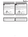
Usable Range
30°
The remote control can be used to control
the projector within the ranges shown in the
illustration.
30°
Remote control
signal transmitters
30°
Note
The signal from the remote control can be
reflected off a screen for easy operation.
However, the effective distance of the signal may differ depending on the screen
material.
23' (7 m)
Remote control
Rear View
Remote control sensor
30°
When using the remote control:
30°
Ensure not to drop, expose to moisture or high
temperature.
The remote control may malfunction under a
fluorescent lamp. In this case, move the projector away from the fluorescent lamp.
23' (7 m)
30°
Remote control
signal transmitters
Remote control
Inserting the Batteries
The batteries (two R-03 batteries ("AAA"
size, UM/SUM-4, HP-16 or similar)) are supplied in the package.
1
Press the mark on the cover and
slide it in the direction of the arrow.
2
Insert the batteries.
Insert the batteries making sure the poand
larities correctly match the
marks inside the battery compartment.
3
Attach the cover and slide it until it clicks into place.
Incorrect use of the batteries may cause them to leak or explode. Please follow the precautions below.
Caution
Insert the batteries making sure the polarities correctly match the
and
marks inside the battery compartment.
Batteries of different types have different properties, therefore do not mix batteries of different types.
Do not mix new and old batteries.
This may shorten the life of new batteries or may cause old batteries to leak.
Remove the batteries from the remote control once they have run out, as leaving them in can cause them to leak.
Battery fluid from leaked batteries is harmful to skin, therefore ensure to first wipe them and then remove them
using a cloth.
The batteries included with this projector may run down in a short period, depending on how they are kept.
Ensure to replace them as soon as possible with new batteries.
Remove the batteries from the remote control if you will not be using the remote control for a long time.
14
EIP-3500
Connection Pin Assignments
INPUT 1/INPUT 2 and OUTPUT RGB Signal Terminal: 15-pin Mini D-sub female connector
RGB Input
11
15
1
6
5
10
1.
2.
3.
4.
5.
6.
7.
8.
9.
10.
11.
12.
13.
14.
15.
Component Input
Video input (red)
Video input (green/sync on green)
Video input (blue)
Not connected
Not connected
Earth (red)
Earth (green/sync on green)
Earth (blue)
Not connected
GND
Not connected
Bi-directional data
Horizontal sync signal: TTL level
Vertical sync signal: TTL level
Data clock
1.
2.
3.
4.
5.
6.
7.
8.
9.
10.
11.
12.
13.
14.
15.
PR (CR)
Y
PB (CB)
Not connected
Not connected
Earth (PR)
Earth (Y)
Earth (PB)
Not connected
Not connected
Not connected
Not connected
Not connected
Not connected
Not connected
RS-232C Terminal: 9-pin Mini DIN female connector
1
2
4
5
6
3
Pin No.
1
2
3
4
5
6
7
8
9
Signal
Name
I/O
RD
SD
Receive Data
Send Data
SG
Signal Ground
Reference
Not connected
Connected to internal circuit
Connected to internal circuit
Not connected
Connected to internal circuit
Not connected
Connected to Pin 8
Connected to Pin 7
Not connected
Input
Output
RS
CS
9
7
8
DIN-D-sub RS-232C adaptor: 9-pin D-sub male connector
1
6
5
Pin No.
1
2
3
4
5
6
7
8
9
9
Signal
Name
I/O
RD
SD
Receive Data
Send Data
SG
Signal Ground
Reference
Not connected
Connected to internal circuit
Connected to internal circuit
Not connected
Connected to internal circuit
Not connected
Connected to internal circuit
Connected to internal circuit
Not connected
Input
Output
RS
CS
Note
Pin 8 (CS) and Pin 7 (RS) are short circuited inside the projector.
RS-232C Cable recommended connection: 9-pin D-sub female connector
5
9
Pin No.
1
2
3
4
5
6
7
8
9
1
6
Signal
CD
RD
SD
ER
SG
DR
RS
CS
CI
Pin No.
1
2
3
4
5
6
7
8
9
Signal
CD
RD
SD
ER
SG
DR
RS
CS
CI
Note
Depending on the controlling device used, it may be necessary to connect Pin 4 and Pin 6 on the controlling
device (e.g. computer).
Projector
Pin No.
4
5
6
Computer
Pin No.
4
5
6
USB Terminal: 4-pin B-type USB female connector
4 3
Pin No.
1
2
3
4
Signal
VCC
USB
USB
SG
LAN Terminal : 8-pin RJ-45 modular connector
Name
USB power
USB data
USB data
GND
8... 1
1 2
15
Pin No.
1
2
3
4
Signal
TX
TX
RX
Pin No.
5
6
7
8
Signal
RX
EIP-3500
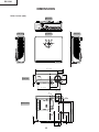
DIMENSIONS
Units: inches (mm)
Side View
/16 (1.5)
Rear View
Side View
9
/64 (3.5)
11 7/64 (282)
1
Top View
12 7/32 (310)
2 3/16
(55.5)
3 33/64 (89)
13/64
(5)
Front View
1 59/64
(48.5)
2 11/64 (55.05)
3 15/16 (99.95)
5 7/64
5 7/64 (129.5)
(129.5)
7
1 5/32 1 /32
(29.1) (30.9)
M4
M4
5
9
/16 (14)
/8 (15.5)
1 3/4
1 7/32
(44.1) (30.9)
16
8 7/8 (225.3)
M4
8 9/32 (210.3)
M4
4 3/16 (106.3)
Bottom View
EIP-3500
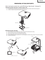
REMOVING OF MAJOR PARTS
* Before removing the projection lens, set the IRIS setting to “High Contrast”. (See page 25.)
1. Removing the lamp door and the lamp unit
1-1. Loosen the lamp door fixing screw, slide the lamp door in allow direction and lift off the lamp door.
1-2. Loosen 2 lamp unit fixing screws and lift off the lamp unit.
Lamp Unit
1-2
Lamp Door
1-1
2. Removing the top body
2-1.
2-2.
2-3.
2-4.
2-5.
Insert a postcard or such thick paper under the lens barrel and between the body.
Remove 6 fixing screws for the top and bottom bodies.
Remove the fixing screw for the top body (terminal side).
Press and hold the areas (marked with *) and disengage the claws on the top body to remove the top body.
Draw out the postcard.
Top Body
To protect the lens barrel
against scratches
2-4
2-3
Bottom Body
2-1
2-2
Short neighborhood
(10 cm)
2-5
Long neighborhood
(15 cm)
Thick paper such as postcard
17
EIP-3500
3. Attaching the top body (For the screws to apply, refer back to "2. Removing
the top body".)
3-1. Insert the postcard over the lens barrel.
3-2. Place the top body in position. Make sure the four hooks are tightly caught.
3-3. Draw out the postcard.
Top Body
3-2
Bottom Body
3-3
3-1
Thick paper such as postcard
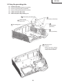
4. Removing the main PWB unit and the peripheral units
4-1.
4-2.
4-3.
4-4.
4-5.
4-6.
4-7.
4-8.
4-9.
Remove 2 main PWB fixing screws (terminal side).
Remove 8 main PWB fixing screws.
Remove 14 connectors from the main PWB.
Pull out the switch bracket connector and remove 3 fixing screws.
Remove the fixing screw for the front R/C PWB.
Remove 2 fixing screws for the A/F holder unit.
Lift off the main PWB in an oblique direction from the optical mechanism unit side.
Remove the speaker holder ass’y.
Remove 2 fixing screws and remove the ballast output socket.
Main PWB Unit
4-3
4-4
[RA]
[FC]
[FA]
[FB]
[TO]
Earth Lead Wire
4-2
[TF]
Switch Bracket Unit
4-9
[DD]
[SC5001]
[CW] [FD]
[AZ]
[AI] [SO]
4-5
[EA]
4-7
Front R/C PWB
4-1
4-8
4-6
Speaker
Holder
Ass'y
A/F Holder unit
18
EIP-3500
5. Removing the optical mechanism unit
5-1. Remove the fixing screw for the optical mechanism unit from the bottom body.
5-2. Remove 5 fixing screws for the optical mechanism unit.
5-3. Remove the duct.
5-2
Duct
5-3
Optical Mechanism Unit
5-1
6. Removing the ballast/power supply unit
6-1. Remove 2 fixing screws for the ballast/power supply unit.
6-2. Remove the fixing screw for the ballast/power supply unit (terminal side).
6-1
Ballast/
Power supply Unit
6-2
19
EIP-3500
7. Removing the ballast/power supply unit
7-1.
7-2.
7-3.
7-4.
Remove the fixing screw for the rear R/C PWB unit.
Remove 4 fixing screws, 4 WH bosses and the edge saddle for the ballast unit.
Remove 11 fixing screws and 5 WH bosses for the power supply unit.
Remove 4 fixing screws from the exhaust fans and fan guard.
7-3
Power Supply PWB Unit
7-3
7-1
7-3
Rear R/C PWB Unit
7-4
7-3
Power Supply Unit
Fan guard
7-2
7-3
Exhaust fans
7-2
7-3
Edge saddle
7-3
Ballast Unit
7-2
8. Removing the peripheral units
8-1. Remove 4 fixing screws for the front adjuster unit.
8-2. Remove 8 bracket fixing screws and remove the bracket A, bracket B and earth plate.
8-2
Bracket A
Bracket B
Earth Plate
8-1
Front Adjuster Unit
Please move "Bracket A" to the bottom of
"Earth Plate". (See page 21.)
Front Adjuster Unit
20
EIP-3500
9. Fixing the grounding plate
9-1.
9-2.
9-3.
9-4.
9-5.
9-6.
9-7.
Install the four nuts.
Fit the reinforcement (bracket A) in position.
Place the grounding plate as specified.
Fit the reinforcement (bracket B) in position.
Tighten up the four M3 screws.
Tighten up the four M4 screws.
Melt the six pins of the grounding plate.
9-6 M4 screws (4 locations)
Reinforcement
9-4 (bracket B)
9-5
M3 screws (4 locations)
9-2
Reinforcement
(bracket A)
9-3 Grounding plate
9-1
Nuts (4 locations)
9-7 Melt the six pins.
Precaution:
* Melt the pins with a soldering
iron to fix the grounding plate.
Finally check for looseness.
21
EIP-3500
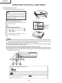
RESETTING THE TOTAL LAMP TIMER
● Resetting the Lamp Timer
Reset the lamp timer after replacing the lamp.
Info
Make sure to reset the lamp timer only
when replacing the lamp. If you reset the
lamp timer and continue to use the same
lamp, this may cause the lamp to become
damaged or explode.
1
AC socket
POWER button
Connect the power cord.
Plug the power cord into the AC socket
of the projector.
ENTER button
2
" button
Reset the lamp timer.
While simultaneously holding down
and
MENU button
,
on the projector, press
on the projector.
"LAMP 0000H" is displayed, indicating
that the lamp timer is reset.
Lamp
It is recommended that the lamp unit (optional: AH-35001) be replaced when the remaining lamp life
becomes 5% or less, or when you notice a significant deterioration in the picture and color quality.
The lamp life (percentage) can be checked with the on-screen display.
Purchase a replacement lamp unit of type AH-35001 from your place of purchase, nearest EIKI Authorized Projector Dealer or Service Center.
The warning lights on the projector indicate problems inside the projector.
If a problem occurs, either the temperature indicator or the lamp indicator will illuminate red, and
the projector will enter the standby mode. After the projector has entered the standby mode, follow
the procedures given below.
Maintenance Indicators
Power indicator
Lamp indicator
Temperature warning indicator
About the temperature warning indicator
If the temperature inside the projector increases, due to blockage of the air vents, or the setting location,
"
" will illuminate in the lower left corner of the picture. If the temperature keeps on rising, the lamp will
turn off and the temperature warning indicator will blink, the cooling fan will run for a further 90 seconds, and
then the projector will enter the standby mode. After "
described on operation manual.
22
" appears, ensure to perform the measures
EIP-3500
Maintenance indicator
Abnormal
Normal
Temperature
warning
indicator
Lamp
indicator
Off
Problem
The internal
Red on
temperature is
(Standby)
abnormally high.
Green on
Green blinks Red on
when the lamp
is warming up
or shutting
down.
Red on
(Standby)
Cause
Possible solution
Blocked air intake
Relocate the projector to an area
with proper ventilation
Cooling fan breakdown
Internal circuit failure
Clogged air intake
Take the projector to your nearest
EIKI Authorized Projector Dealer
or Service Center for repair.
Clean the exhaust and intake
vents.
The lamp does
not illuminate.
The lamp is shut
down abnormally.
Disconnect the power cord from
the AC outlet, and then connect it
again.
Time to change
the lamp.
Remaining lamp life
becomes 5% or less.
The lamp does
not illuminate.
Burnt-out lamp
Lamp circuit failure
Carefully replace the lamp.
Take the projector to your nearest
EIKI Authorized Projector Dealer
or Service Center for repair.
Please exercise care when
replacing the lamp.
Info
If the temperature warning indicator illuminates and the projector enters the standby mode, check whether
any of the ventilation holes are blocked and then try turning the power back on. Wait until the projector has
cooled down completely before plugging in the power cord and turning the power back on.
(At least 10 minutes.)
If the power is turned off for a brief moment due to power outage or some other cause while using the
projector, and the power supply recovers immediately after that, the lamp indicator will illuminate in red
and the lamp may not be lit. In this case, unplug the power cord from the AC outlet, replace the power
cord in the AC outlet and then turn the power on again.
Do not unplug the power cord after the projector has entered the standby mode and while the cooling fan
is running. The cooling fan runs for about 90 seconds.
23
EIP-3500
THE OPTICAL UNIT OUTLINE
Layout for proper setup of the optical components and parts (top view)
(Schematic diagram)
Reflection mirror
Projection lens
Color wheel
Lamp
Field lens
DMD
Rod
UV Filter
Illumination lenses 1
Illumination lenses 2
Item
Lamp
Color wheel
Rod
Illumination lenses
Reflection mirror
Field lens
DMD
Projection lens
Function
Light source. DC high-pressure mercury lamp.
Splits light from the light source into R, G, B and W through a color filter.
Assures uniform light ray.
Focus light from the rod on DMD.
Reflects light from the illumination lenses toward DMD.
Focuses light from the reflection mirror on DMD and then the light from DMD to
the projection lens.
Turns the internal micromirror ON/OFF at the rate of color component of each dot
of the input source to reflect light.
Enlarges light from DMD and projects it on a screen.
24
EIP-3500
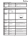
Air blow direction
Exhaust fans 1 and 2
After replacing the DMD, if shading is present on the screen as shown in Figure 1, adjust the lighting area of the
DMD by turning the adjustment screws for the optical engine.
1. Loosen the fixing screw for the adjustment lever 1. Adjust the lighting area by adjustment lever 2 and
then tighten the fixing screw for the adjustment lever 1.
2. If the above adjustment is insufficient, loosen the fixing screw 3 and set the adjusting screws 4 and 5.
Finally tighten up the fixing screw 3.
2
3
4
1
Tightening order: 1
2
3
4
Screw tightening torque: 0.78±0.1 N-m
Shading
Fig. 1
When mounting the DMD element,
tighten the four screws evenly.
When removing a projection lens, please change the setting of Iris to "high contrast" beforehand.
25
EIP-3500
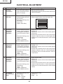
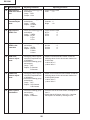
ELECTRICAL ADJUSTMENT
No.
Adjusting point
Adjusting conditions
Adjusting procedure
1
EEPROM
initialization
1. Turn on the power (with the
lamp on) and warm up the
set for 15 minutes.
» Make the following settings.
Press S3563 to call the process mode and execute
"SS2" on SS menu.
2
Adjustment of
CW index
1. Feed 64 STEP color bar or
RGB lamp pattern (XGA 60
Hz) to input 1.
2. Select the following group
and subject.
Group: DLP
Subject: Index Delay
1. Adjust the lamp patterns of RGB so that smooth
patterns appear without color blend and noise.
W
R
G
B
3
R Contrast
adjustment
(manual or
automatic)
1. Send white/black window
pattern signals with 91%
(0.64 Vpp)/0% of amplitude
level of XGA 60Hz to input
1.
2. Select the following group
and subjects.
Group : AD
Subject : R-Contrast
(Process GAMMA interlock)
1. Check the fixed value.
R-Bright: 63
2. Observe the chroma of 91% white window pattern
with CA100.
3. Increase the R-Contrast value on the screen with bit
dropouts. Adjust the value to +5 when bright red bit
dropouts occur on the black and the x value exceeds
30/100.
4
G Contrast
adjustment
(manual or
automatic)
1. Send white/black window
pattern signals with 91%
(0.64 Vpp)/0% of amplitude
level of XGA 60Hz to input
1.
2. Select the following group
and subjects.
Group : AD
Subject : G-Contrast
(Process GAMMA interlock)
1. Check the fixed value.
G-Bright : 63
2. Observe the chroma of 91% white window pattern
with CA100.
3. Increase the G-Contrast value on the screen with bit
dropouts. Adjust the value to +5 when bright green
bit dropouts occur on the black and the x value exceeds 30/100.
5
B Contrast
adjustment
(manual or
automatic)
1. Send white/black window
pattern signals with 91%
(0.64 Vpp)/0% of amplitude
level of XGA 60Hz to input
1.
2. Select the following group
and subjects.
Group : AD
Subject : B-Contrast
(Process GAMMA interlock)
1. Check the fixed value.
B-Bright: 63
2. Observe the chroma of 91% white window pattern
with CA100.
3. Increase the B-Contrast value on the screen with bit
dropouts. Adjust the value to +5 when bright blue bit
dropouts occur on the black and the x value exceeds
30/100.
6
DTV Bright/
Contrast adjustment
1. Select the following group
and subjects.
Group : DTV
Subject : Contrast
Bright
1. Check the fixed value.
Contrast : 4
Bright : 40
26
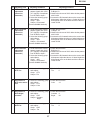
EIP-3500
No.
Adjusting point
Adjusting conditions
Adjusting procedure
7
DTV R Contrast
adjustment
(manual or
automatic)
1. Send white/black window
pattern signals with 100%
(0.7 Vpp)/0% of amplitude
level of 480P to input 1.
2. Select the following group
and subjects.
Group : AD2
Subject : R-Contrast2
(Process GAMMA interlock)
1. Check the fixed value.
R-Bright: 63
2. Observe the chroma of 100% white window pattern
with CA100.
3. Increase the R-Contrast2 value on the screen with
bit dropouts. Adjust the value to +5 when bright red
bit dropouts occur on the black and the x value exceeds 30/100.
8
DTV G Contrast
adjustment
(manual or
automatic)
1. Send white/black window
pattern signals with 100%
(0.7 Vpp)/0% of amplitude
level of 480P to input 1.
2. Select the following group
and subjects.
Group : AD2
Subject : G-Contrast2
(Process GAMMA interlock)
1. Check the fixed value.
G-Bright : 63
2. Observe the chroma of 100% white window pattern
with CA100.
3. Increase the G-Contrast2 value on the screen with
bit dropouts. Adjust the value to +5 when bright green
bit dropouts occur on the black and the x value exceeds 30/100.
9
DTV B Contrast
adjustment
(manual or
automatic)
1. Send white/black window
pattern signals with 100%
(0.7 Vpp)/0% of amplitude
level of 480P to input 1.
2. Select the following group
and subjects.
Group : AD2
Subject : B-Contrast2
(Process GAMMA interlock)
1. Check the fixed value.
B-Bright: 63
2. Observe the chroma of 100% white window pattern
with CA100.
3. Increase the B-Contrast2 value on the screen with
bit dropouts. Adjust the value to +5 when bright blue
bit dropouts occur on the black and the x value exceeds 30/100.
10
Adjustment of
DTV Tint
1. Select the following group 1. Check the fixed value.
and subject.
Tint
:5
Group : DTV
Subject : Tint
11
Adjustment of
DTV color saturation
1. Select the following group 1. Check the fixed value.
and subject.
Color
: 12
Group : DTV
Subject : Color
12
Adjustment of
DVD Bright /
Contrast
1. Select the following group 1. Check the fixed value.
and subject.
Contrast : 4
Group : DVD
Bright
: 40
Subject : Contrast
Bright
13
Adjustment of
DVD Tint
1. Select the following group 1. Check the fixed value.
and subject.
Tint
:5
Group : DVD
Subject : Tint
27
EIP-3500
No.
Adjusting point
Adjusting conditions
Adjusting procedure
14
Adjustment of
1. Select the following group 1. Check the fixed value.
DVD color saturaand subject.
Color
: 12
tion
Group : DVD
Subject : Color
15
Video Bright /
Contrast adjustment
1. Select the following group
and subjects.
Group : VIDEO
Subject : Contrast
Bright
16
Adjustment of
VIDEO Tint
1. Select the following group 1. Check the fixed value.
and subject.
N-Tint
:5
Group : VIDEO
P-Tint
:5
Subject : N-Tint
S-Tint
:5
P-Tint
S-Tint
17
Adjustment of
VIDEO color
saturation
1. Select the following group 1. Check the fixed value.
and subject.
N-Color
:6
P-Color
:6
Group : VIDEO
S-Color
:6
Subject : N-Color
P-Color
S-Color
18
RGB white
balance adjustment
1. Send gray pattern signals
with 50% of amplitude level
of XGA60Hz.
2. Select the following group
and subjects.
Group : DLP
Subject : R-Contrast
B-Contrast
1. Adjust R-Contrast and B-Contrast so that the
following values for the chroma are obtained on
CL200 base:
x value: 297 ± 5
y value: 305 ± 5
19
sRGB white
balance adjustment
1. Send gray pattern signals
with 50% of amplitude level
of XGA60Hz.
2. Select the following group
and subjects.
Group : DLP
Subject : S-G-Contrast
S-B-Contrast
1. Adjust S-G-Contrast and S-B-Contrast so that the
following values for the chroma are obtained on
CL200 (6500K) base:
x value: 320 ± 5
y value: 336 ± 5
20
Auto keystone
initialization
1. Select the following group
and subjects.
Group : LINE
Subject : Calibration
1. Place the unit on the level surface, and adjust to 1
from 0.
2. Check that the K-Sensor value is 0 ± 3 and that
the keystone is caused by inclining the unit.
28
1. Check the fixed value.
Contrast : 4
Bright
: 40
EIP-3500
Adjustment when assembling
No.
Adjusting point
21
Adjustment of
DLP voltage
Adjusting conditions
Adjusting procedure
1. Read voltage rank of DLP
description.
2. Set the switch corresponding to the rank which has
been read.
1. Carry out adjustment when DLP chip has been replaced or combination of chip and formatter has been
changed.
Rank:
B C D E
Setting value: 1 2 3 4
Checkpoints
No.
Adjusting point
Adjusting conditions
Adjusting procedure
22
Adjustment of
DLP Brightness
1. Select the following group
and subject.
Group : DLP
Subject : R-Bright
G-Bright
B-Bright
1. Check the fixed value.
Fixed value
: 32
23
RGB tone
reproduction
adjustment
1. Feed the SMPTE pattern
signal.
1. Make sure the 100% and 95% white as well as the
0% and 5% black gradations are visible.
24
White balance
checking and
readjustment
1. RGB Inputt, sRGB Input,
DTV Input, DVD Input,
VIDEO Input
Check that there is no deviation of white balance with
the monitor.
25
Off-timer performance
1. Select the following group 1. Select OFF from the process mode.
and subjects.
Make sure the off-timer starts with 5 minutes
Group : LAMP
onscreen and count one minute in one second.
Subject : OFF
And then indication is 0 minute, the power supply
of the set is cut off.
26
Thermistor
performance
checking
1. Heat the thermistor with a
hair dryer.
1. Make sure that the temperature is indicated.
27
Auto sync
performance
checking
1. Feed the phase check pattern signal.
1. In the VGA, SVGA, XGA and SXGA modes, make
sure the Clock, Phase, H-Pos and V-Pos settings
can be automatically adjusted.
28
USB operation
check
1. Connect to a PC with a
USB cable.
1. Check that advance/reverse operation on PC screen
is possible by using remote control.
29
LAN operation
check
1. Connect to a PC with a
LAN cable.
1. Check that communication is possible.
29
EIP-3500
No.
Adjusting point
30
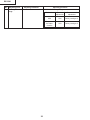
Delivery settings
Adjusting conditions
Adjusting procedure
1. Make the following settings.
Destination
Process
30
Remote control
adjustment
adjustment
USA
SS4
Factory setting at 4
Europe and
the Other
Contries
SS3
Factory setting at 3
EIP-3500
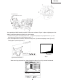
AF (autofocus) inspection
< Camera >
Required conditions:
1. Place the unit in front of the screen (size: 60-inch diagonal) at the distance of 1.8m. There is no light source such as
a fluorescent light or reflector in the background.
2. Focus is adjusted correctly.
3. RGB input of 256-gradation pattern.
Method:
1. Send AF inspection command ("_CMR 1").
2. Check that the response command is "OK".
< AF function >
Required conditions:
1. Place the unit in front of the screen (size: 60-inch diagonal) at the distance of 1.8m. There is no light source such as
a fluorescent light or reflector in the background.
Method:
1. Press the AF button. AF operation must end within 11 seconds.
2. Check that the difference from the just focus point is within ±15cm.
* The above time applies when the focus start position is not fixed.
After the camera inspection, AF operation must end within 6 seconds.
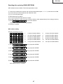
Calling and quitting the process mode with the control keys on this model.
∗ Although it is possible for the process OUT to exit using the process menu, the IN/OUT toggle command is also
available considering the existing specification.
1. Calling and quitting
With the menu not displayed, press the "ENTER", "VOL+", "VOL-", "VOL+", "VOL-", "ENTER" and "MENU" keys on
the set.
2. Others
Press the S3563 process key (toggle) on the main PWB to call and quit the process menu.
Note: When adjusting in the process mode, set a signal with a vertical frequency of 60 Hz or no signal. (May not be
properly adjusted with other signals.)
Resetting the lamp timer for this model
1. Resetting procedure
In Stand-by, run this command to clear the operating time of the lamp to 0 and turn on the power.
Press and hold "DOWN", "ENTER", and "MENU", and then press the "ON" key of the set.
Forced disabling of the System-Lock of this model
1. Disabling procedure
With System-Lock input window onscreen, press the "MENU", "ENTER", "MENU", "ENTER", "MENU", "ENTER"
and "MENU" keys on the set.
31
EIP-3500
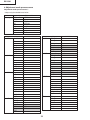
» Adjustment mode process menu
Adjustment mode process menu 1
* Adjust only the shaded items below.
First layer
Adjustment Process Menu
DTV
VERSION
DVD
SS
VIDEO
TEMP
AD
OPTION
AD2
LAMP
DLP
LINE
VIDEO1
Pedestal
EXIT
second layer
Contrast
Tint
Color
Sharpness
Bright
B-DRIVE
R-DRIVE
EXIT
DVD
Contrast
Tint
Color
Sharpness
Bright
B-DRIVE
R-DRIVE
EXIT
VIDEO
Contrast
N-Tint
P-Tint
S-Tint
N-Color
P-Color
S-Color
Sharpness
Bright
B-DRIVE
R-DRIVE
EXIT
AD
R-Bright
G-Bright
B-Bright
R-Contrast
G-Contrast
B-Contrast
EXIT
DTV
second layer
R-Bright2
G-Bright2
B-Bright2
R-Contrast2
G-Contrast2
B-Contrast2
EXIT
DLP
Index Delay
R-Bright
G-Bright
B-Bright
R-Contrast
G-Contrast
B-Contrast
SR-Cont
SG-Cont
SB-Cont
EXIT
VIDEO1
N-Contrast
P-Contrast
S-Contrast
Color
NT3.58Delay
NT4.43Delay
PAL Delay
SECAM Delay
EXIT
Pedestal R-Bright
G-Bright
B-Bright
R-Contrast
G-Contrast
B-Contrast
EXIT
Initial Value
AD2
4
5
12
2
40
41
41
4
5
12
3
40
41
41
4
5
5
5
6
6
6
3
40
41
41
63
63
63
155
155
155
32
Initial Value
63
63
63
155
155
155
10500
32
32
32
34
34
34
34
34
34
13
13
14
17
1
1
1
3
-10
-10
-10
15
15
15
EIP-3500
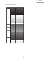
Adjustment mode process menu 2
second layer
VERSION Build
Boot Code
Config
RomCode
GUI
DLP
AF Unit
LAN
EXIT
SS
SS2
SS3 EU
SS4 US
SS5 JPN
SS6 CHIN
EXIT
TEMP
Temp1
Temp2
EXIT
OPTION Pixel Gamma
DLP Gamma
EXIT
LAMP
Current Time
History1
History2
History3
History4
TOTAL TIME
EXIT
LINE
OFF
LED CHECK
Calibration
K-Senser
EXIT
Initial Value
Parameter of sensor1
Parameter of sensor2
Standard RGB
4
Current time of use
One Earlier
Two Earlier
Three Earlier
Four Earlier
Total operating hours
33
EIP-3500
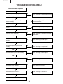
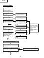
TROUBLESHOOTING TABLE
Checking the basic operation
Does the power LED light up or flash in
red or green?
NO
Go to "Checking the power supply system".
YES
Does the set function with its keys or the
remote controller?
NO
Go to "Checking the peripheral circuits of
the microprocessor".
YES
Does the cooling fan rotate, and the lamp
turn on?
NO
Go to "Checking the lamp light-up".
YES
Is the user menu displayed?
NO
Go to "Checking the peripheral circuits of
the formatter".
NO
Go to "Checking the RGB input".
YES
Does the analog RGB input function
normally?
YES
Does the component input function
normally?
NO
Go to "Checking the component".
YES
Does the VIDEO input function normally?
NO
Go to "Checking of VIDEO input ".
YES
Does the LAN function?
NO
Go to "Checking the LAN".
YES
Does the RS-232C function?
NO
Go to "Checking RS-232C".
YES
Does the autofocus function?
NO
Go to "Checking the autofocus".
YES
End.
34
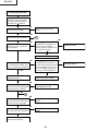
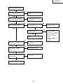
EIP-3500
Checking the power supply system
Is 13V output to pins (9) and (11) of
P1707?
NO
Go to "Checking the power unit".
YES
Is 6V output to pins (1) and (3) of P1707? NO
Go to "Checking the power unit".
YES
Is the connector of P1708 fully inserted? NO
Is the voltage of 6V applied to both ends?
Replace the thermal fuse.
YES
NO
Check IC1776 and peripheral circuits.
Is B+5VAT output from IC1776?
YES
NO
Check IC1708 and peripheral circuits.
Is BU+3.3V output from IC1708?
YES
NO
Check IC1733 and peripheral circuits.
Is BU+2.5V output from IC1733?
YES
Go to "Checking the peripheral circuits of
the microprocessor".
35
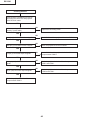
EIP-3500
Checking the power unit
Is each connector of the power unit
fully inserted?
NO
Securely insert the connectors.
YES
Is the lamp door closed completely?
NO
Fix the lamp door with screws.
YES
Is the bimetal broken?
NO
Replace the bimetal switch or restore
by pressing the red button.
NO
Replace F701. If other parts are
damaged, replace them.
NO
Check D707 and the peripheral circuits
of IC702 on the primary side. If
defective, replace them.
YES
Is AC voltage applied to both AC input
ends of DB701?
YES
Is DC voltage of approx. 6.25V output
to both ends of C726?
YES
Is DC voltage of approx. 370V output to NO
the cathode of D701?
YES
Is the specified voltage output to each
output terminal of EA701?
NO
Replace the subunit or check the
primary side circuit.
Replace defective parts if any.
Check the secondary-side circuits of
T701. If defective, replace them.
YES
Check the PWB circuits on each output
side.
Replace the ballast power supply.
36
ABNORMAL
EIP-3500
Checking the peripheral circuits of the
microprocessor
Are the voltages of approx. 3.3V and 2.5V
applied to both ends of C2030 and C2029
respectively?
NO
Go to "Checking the power supply
system".
YES
Are the oscillations of 133MHz and
64MHz output from pin (3) of X2001 and
pin (3) of X2002 respectively?
NO
Check the peripheral circuits of X2001
and X2002.
YES
Does each terminal of R2039, R2040,
R2042, R2048 and R2050 change?
NO
Check IC2201 and IC2202. IC2003 is
defective.
NO
Check IC2203. IC2201 is defective. The
I2C bus does not function normally.
YES
Do pins (95) and (96) of IC2201 change?
YES
Do pins (74) to (77) and (89) to (94) of
IC2201 change when any key is
operated?
NO
IC2201 is defective. The keys do not
function normally.
YES
When the power button is pressed, does
the voltage of pin (7) of IC2005 become
3.3V?
NO
IC2003 is defective.
YES
Do pulse-shaped waveforms appear at
pins (1), (2), (5) and (6) of IC2005?
NO
IC2005 is defective.
YES
Does the voltage of pins (2) and (6) of
IC2006 and pins (3) and (6) of IC2007
change?
NO
IC2006 or IC2007 is defective.
YES
Is the voltage of pin (9) of IC3560 5V?
NO
IC3560 is defective.
YES
Does the fan rotate?
Check the power supply circuit or fan
circuit on the main circuit.
NO
YES
Go to "Checking the lamp light-up".
37
EIP-3500
Checking the lamp light-up
Does each cooling fan
function?
NO
Check the power supply circuit
or fan circuit on the main circuit.
YES
Is the rotating sound of the
color wheel heard?
ABNORMAL
NO
YES
Check IC9102, 9003 and
the peripheral circuits of
the motor driver IC
IC9101.
Go to "Checking the
peripheral circuits of
the formatter".
NORMAL
Replace the color wheel.
Is the discharging sound
heard?
YES
Is the lamp tight in the
socket?
NO
Replace the lamp.
YES
Securely insert the
connectors.
NO
Is DC voltage of approx.
NO
370V applied to both ends
of the ballast power supply?
YES
Go to "Checking the
peripheral circuits of the
formatter".
Is pin (2) of P1707 at the
H level?
NO
Check IC1701, IC2003 and
their peripheral circuits.
38
YES
Go to "Checking the
power unit".
EIP-3500
Checking the peripheral circuits
of the formatter
What is the screen problem?
The rainbow-like screen is
displayed. Each color (R,
G and B) does not match.
The screen is all black.
The problem remains
even after adjusting
"Process menu", "DLP"
and "Index".
Is the socket of
SC9001 connected
properly?
Thick and white
vertical lines (flash).
Other
Are contact terminals
of DMD, the formatter
board and CLGA
dirty?
Is the socket of
SC9001 connected
properly?
YES
YES
Does the color wheel
rotate?
IC9003 and IC9004 are
defective.
YES
Is the voltage of pin (3)
of IC9001 normal
(+2.5V)?
NO
NO
Check the main PWB
and power unit.
NO
Reinstall DMD, optical
mechanism, and
Formatter PWB.
YES
Is the proper voltage
supplied to the socket
of SC9001?
NO
Is there a sine wave of
400MHz at pins (18)
and (20) of IC9001?
YES
IC9001 or its
peripheral circuits are
defective.
YES
Is the voltage of the
positive polarity pin of
C9308 normal (+5V)?
IC9301 or its peripheral
circuits are defective.
YES
IC9003, IC9004,
IC9006 or their
peripheral circuits are
defective.
YES
IC9101, 9102, their
peripheral circuits or
color wheel is defective.
NO
NO
Does the fan rotate?
Does the lamp turn on?
NO
YES
YES
NO
When no signal is sent, is
a pulse signal of 180Hz
present on pin (2) of
P1705 on the main PWB?
Check the color wheel
sensor PWB.
Is the pulse-shaped
waveform supplied to
the pin (14) of P1707
on the main PWB?
YES
NO
NO
YES
Is the voltage of pin (9)
of IC9301 normal
(between +23 and
+26V)?
Check the ballast unit
and power unit.
YES
Is the voltage of pin
(13) of IC9301 normal
(-26V)?
IC9301 or its peripheral
circuits are defective.
YES
NO
Is the voltage of pin
(49) of IC9301 normal
(+7V)?
NO
IC9301 or its
peripheral circuits are
Check the fan circuits.
Is there a pulse signal
of 60MHz at TP9055
(DCLK_L)?
39
IC2003, 1701 or their
peripheral circuits are
defective.
EIP-3500
Checking the RGB input
Send RGB signals to INPUT1
or INPUT2. Use keys on the
main unit or remote control to
select INPUT1 or INPUT2.
NO
Are sync signals input to pins
(30) and (31) of IC3005?
YES
Go to "Checking the sync
signal".
YES
Are picture signals input to pins
(43), (48) and (54) of IC3005?
1
NO
NO
NO
Are picture signals input to
pins (2), (5), (11), (3), (6) and
(10) of IC3003?
YES
When toggling between INPUT1
and INPUT2 by using keys on
the main unit and remote
control, does the voltage of pin
(1) of IC3003 change?
Check Q3123, IC2003 and
peripheral circuits.
YES
Replace IC3003.
NO
Are picture signals input to pins
(1), (5) and (8) of IC4003, and
pins (1), (5) and (8) of IC4004?
YES
Check SC4003, SC4001 and
peripheral circuits.
YES
When toggling between INPUT1 NO
and INPUT2 by using keys on
the main unit and remote control,
does the voltage of pins (2), (4)
and (7) of IC4003, and pins (2),
(4) and (7) of IC4004 change?
YES
Replace IC4003 or IC4004.
NO
Check IC3106, 3107, 3108
and peripheral circuits.
Are picture signals input to pins (43),
(48) and (54), and sync signals input
to pins (30) and (31) of IC3005?
YES
1
NO
Are sync signals output from pins
(64), (65) and (66), and sine wave
output from pin (67) of IC3005?
YES
Are signals input to pins (56),
(58), (62) and (64) of SC2501?
Check IC3005 and peripheral
circuits.
NO
Check IC8001 and peripheral
circuits.
YES
Go to "Checking the peripheral
circuits of the formatter".
40
Check IC4009, IC2003 and
peripheral circuits.
EIP-3500
Checking the Component
Send component signals to
INPUT1 or INPUT2. Use
keys on the main unit or
remote control to select
INPUT1 or INPUT2.
YES
Is picture signal including
sync signal input to pin (46)
of IC3002?
YES
2
NO
Are picture signals input to
pins (8), (9) and (10) of
IC3101?
NO
Check IC4003, IC4004 and
peripheral circuits.
YES
Are picture signals output
from pins (35), (37) and
(39) of IC3101?
NO
1
YES
Are picture signals sent
from pins (76), (77) and
(78) of IC3101 to pins (17),
(18) and (19) of IC3103?
NO
Check IC3101 and
peripheral circuits.
NO
Check IC3103 and
peripheral circuits.
YES
Are picture signals sent
from pins (21), (22) and
(23) of IC3103 to pins (67),
(68) and (69) of IC3101?
YES
Check IC3101 and
peripheral circuits.
41
EIP-3500
Checking of Video input
Send composite VIDEO
signals to INPUT3. Use keys
on the main unit or remote
control to select INPUT3.
Is picture signal input to pin
(1) of IC3103?
NO
Check the VIDEO-IN signal line
of Q3104 and soldering of
J3101.
YES
Check the peripheral circuits of
C3103 and color system
malfunctions.
YES
Is input signal SECAM?
NO
NO
Are picture signals input to
pins (39) and (41) of IC3103?
YES
Check IC3105 and peripheral
circuits.
YES
2
Are picture signals output
from pins (21), (22) and (23)
of IC3103?
Do pulse-shaped waveforms appear NO
at pins (15) and (16) of IC3105?
NO
Do pulse-shaped waveforms appear NO
at pins (13) and (14) of IC3103?
YES
YES
Check IC3103 and peripheral
circuits.
Are picture signals input to
pins (67), (68) and (68), and
output from pins (35), (37)
and (38) of IC3101?
NO
The I2C bus line does
not function normally.
Check IC2201, IC2003,
IC2005, IC2006, IC2007
and their peripheral
circuits.
Check if IC connected to
I2CBUS functions
normally.
Do pulse-shaped waveforms appear NO
at pins (55) and (56) of IC3101?
YES
Check IC3101 and peripheral
circuits.
YES
1
Checking of S-Video input
Send S terminal (Y and C) signals to INPUT4.
Use keys on the main unit or remote control to
select INPUT4.
Are picture signals output from pins (43) and
(44) of IC3103?
NO
Check the soldering of J3101.
YES
2
42
EIP-3500
Checking of Sync signal
NO
Check IC4008 and peripheral
circuits.
Are HV sync signals sent to
pins (1) and (6) of IC4010?
YES
NO
IC4008 and IC4010 are
defective.
Are HV sync signals sent to
pins (22) and (23) of IC3002?
YES
Are sync signals sent to pins
(28) and (29) of IC3002?
NO
Is a clock of 27MHz sent to pin
(42) of IC3002?
Do signals of pins (21) and (22)
of IC3002 change?
YES
Check IC3002 and peripheral
circuits.
NO
IC3005 and peripheral circuits
are defective.
Are sync signals sent to pins
(65) and (64) of IC3005?
YES
Is the timing of vertical and
horizontal sync signals
correct?
Sync signal is normal.
NO
Is the signal generator (input
source) correct?
Check X3001 and
peripheral circuits.
YES
YES
YES
NO
YES
IC2003 and peripheral circuits
are defective.
NO
Set the signal source correctly.
43
NO
The I2C bus line does not
function normally.
Check IC2201, IC2003,
IC2005, IC2006, IC2007
and their peripheral
circuits.
Check if IC connected to
I2CBUS functions
normally.
EIP-3500
Checking the autofocus
Is dust, dirt or damage present
on the auto focus sensor
cover?
NO
Remove the dust and dirt, or
replace.
YES
NO
Are voltages of 3.3V, 1.5V and
2.8V applied to pin (4) of X5001,
pin (94) of IC5003 and pin (5) of
IC5008 respectively?
Check the power supply circuit
and its peripheral circuits.
YES
NO
X5001 is defective.
Is a clock (49MHz) output from
pin (3) of X5001?
YES
Is a clock (12.27MHz) output
from pin (108) of X5003?
NO
YES
NO
Does the signal of pin (6) of
IC5004 change right after 3.3V
is applied?
Check IC5003.
YES
Check IC5004.
Is a clock sent to pin (93) of
IC5003?
NO
YES
Is the camera FPC properly
connected to the connector?
YES
The camera is defective.
When auto focus is performed,
does pin (121) of IC5003
change?
NO
Check IC5005 and IC5006.
YES
Check the motor drive circuit.
44
NO
Connect properly.
EIP-3500
Checking the LAN
LAN communication is disabled even
though connecting the control PC with a
LAN cable. The LINK LED (green) does
not light up.
YES
Are the connection of connecting cable
and the settings of IP address, sub-net
address and default gateway correct?
NO
YES
Check the connecting cable and LAN settings. If the
LAN settings are unknown, contact the network
administrator.
If the network settings cannot be saved, replace
IC8003 (EEP ROM) as it may be defective.
Note: When IC8003 (EEP ROM) is replaced, the MAC
address returns to default. Refer to "Resetting
after replacing IC8003 (EEP ROM)" to reset.
NO
Are the network device (e.g. Hub)
between the control PC and EIP-3500
and cable normal?
Repair defective parts in the network.
YES
When data is sent from the control PC, do
pins (30) and (31) of IC8201 (PHY
receiver) receive signals?
NO
Check the peripheral circuit of J8201 (RJ-45 jack
with built-in transformer).
YES
Check the PHY receiver IC8201 and the
peripheral circuits of the microprocessor
IC8001.
45
EIP-3500
Checking RS-232C
Communication is disabled even though
connecting the control PC and projector
with a RS-232C cable.
YES
Is the connecting cable connected
correctly? (cross cable)
NO
Replace the connecting cable.
YES
NO
Does pin (8) of IC8002 receive a signal?
Check R8002 and the peripheral circuits of SC8001.
YES
NO
Check the peripheral circuits of IC8002.
Does pin (4) of IC8202 receive a signal?
YES
Do pin (3) of IC8202 output a signal?
NO
Check IC8202 and the peripheral circuits of the
microprocessor IC8001.
YES
NO
Does pin (106) of IC2201 receive a
signal?
Check the peripheral circuits of the microprocessor
IC8001 and IC2201.
YES
NO
Do pin (105) of IC2201 output a signal?
Check the peripheral circuits of the microprocessor
IC2003 and IC2201.
YES
Check the peripheral circuits of the
microprocessor IC8001.
46
EIP-3500
Resetting after replacing IC8003 (EEP ROM)
MAC address returns to default. Follow the steps below to reset.
1 Open the top cabinet of the projector and confirm the MAC address (MAC: ************) of the seal on the PWB.
2 Connect the control PC and projector with a RS-232C cable.
3 Turn on the AC power supply.
4 EEP ROM returns to default.
5 Turn off the AC power supply and turn on again.
6 Set MAC address by using the RS-232C command. (Refer to "MAC address setting" for the setting procedure.)
7 Enter
and check the response.
Check that it is the same as the set MAC address.
8 Setting is completed.
MAC address setting
RS-232C commands to be used
*1
1st byte of the MAC address
*2
2nd byte of the MAC address
*3
3rd byte of the MAC address
*4
4th byte of the MAC address
*5
5th byte of the MAC address
*6
6th byte of the MAC address
*7
7th byte of the MAC address
*8
8th byte of the MAC address
*9
9th byte of the MAC address
*10
10th byte of the MAC address
*11
11th byte of the MAC address
*12
12th byte of the MAC address
1 Enter
and [*2], and press "ENTER".
Responds "OK".
2 Enter
and [*2], and press "ENTER".
Responds "OK".
3 Enter
and [*2], and press "ENTER".
Responds "OK".
4 Enter
and [*2], and press "ENTER".
Responds "OK".
5 Enter
and [*2], and press "ENTER".
Responds "OK".
6 Enter
and [*2], and press "ENTER".
MAC address setting is completed.
47
EIP-3500
CHASSIS LAYOUT
H
G
F
E
D
FORMATTER UNIT
DUNTKC613WEF0
C
POWER UNIT
RDENCA118WJZZ
B
A
1
2
3
4
5
6
48
7
8
9
10
EIP-3500
FRONT R/C RECEIVER UNIT
DUNTKC615WEF3
MAIN UNIT
DUNTKC612WEF3
BALLAST UNIT
RDENCA088WJZZ
REAR R/C RECEIVER UNIT
DUNTKC681WEF3
10
11
12
13
14
15
49
16
17
18
19
EIP-3500
BLOCK DIAGRAM
H
G
F
E
D
C
B
A
1
2
3
4
5
6
50
7
8
9
10
EIP-3500
10
11
12
13
14
15
51
16
17
18
19
EIP-3500
OVERALL WIRING DIAGRAM
H
G
F
E
D
C
B
A
1
2
3
4
5
6
52
7
8
9
10
EIP-3500
10
11
12
13
14
15
53
16
17
18
19
EIP-3500
WAVEFORMS
1 IC3101 (28) pin
(VS-OUT)
H : 4m sec/div
V : 1V/div
2 IC3101 (29) pin
(HS-OUT)
H : 20µ sec/div
V : 1V/div
3 IC3101 (31) pin
(SCP-IN)
H : 20µ sec/div
V : 1V/div
4 IC3101 (35) pin
(R-OUT)
H : 10µ sec/div
V : 500mV/div
5 IC3101 (37) pin
(G-OUT)
H : 10µ sec/div
V : 500mV/div
6 IC3101 (39) pin
(B-OUT)
H : 10µ sec/div
V : 500mV/div
7 IC3103 (43) pin
(C2-IN)
H : 10µ sec/div
V : 500mV/div
8 IC3103 (44) pin
(CVBS/Y2-IN)
H : 10µ sec/div
V : 500mV/div
9 IC3105 (7) pin
(YCIN)
H : 10µ sec/div
V : 200mV/div
0 IC3105 (19) pin
(FSC)
H : 100n sec/div
V : 200mV/div
q IC3103 (41) pin
(COMB-Y)
H : 10µ sec/div
V : 200mV/div
w IC3103 (39) pin
(COMB-C)
H : 10µ sec/div
V : 200mV/div
e SC2501 (62) pin
(DCLK)
H : 10n sec/div
V : 1V/div
r SC2501 (58) pin
(DHS)
H : 10µ sec/div
V : 1V/div
t SC2501 (64) pin
(DVS)
H : 4m sec/div
V : 1V/div
y P1707 (14) pin
(LAMP_EN_POW)
H : 2m sec/div
V : 2V/div
u P1705 (2) pin
(CWINDEX)
H : 2m sec/div
V : 1V/div
i IC9101 (16) pin
(OSC)
H : 100n sec/div
V : 2V/div
o SC2502 (1) pin
(CWY1)
H : 400µ sec/div
V : 5V/div
p SC2502 (4) pin
(CWCTR)
H : 200µ sec/div
V : 5V/div
54
EIP-3500
PRINTED WIRING BOARD ASSEMBLIES
H
G
F
FRONT R/C Unit (Side A)
FRONT R/C Unit (Side B)
REAR R/C Unit (Side A)
REAR R/C Unit (Side B)
E
D
C
B
A
1
2
3
4
55
5
6
EIP-3500
H
G
F
E
D
C
B
A
MAIN Unit (Side-A)
1
2
3
4
5
6
56
7
8
9
10
EIP-3500
10
11
12
13
14
15
57
16
17
18
19
EIP-3500
H
G
F
E
D
C
B
A
MAIN Unit (Side-B)
1
2
3
4
5
6
58
7
8
9
10
EIP-3500
10
11
12
13
14
15
59
16
17
18
19
EIP-3500
H
G
F
E
D
C
B
FORMATTER Unit (Side-A)
A
1
2
3
4
60
5
6
EIP-3500
H
G
F
E
D
C
B
FORMATTER Unit (Side-B)
A
1
2
3
4
61
5
6
EIP-3500
H
G
F
E
D
C
B
A
POWER BALLAS Unit (Side A)
1
2
POWER BALLAST Unit (Side B)
3
4
62
5
6
E IP -3500
R ef. No.
PA R T S L IS T
Part No.
Des c ription
C ode
R ef. No.
MA IN UNIT
P arts marked with " " are important for maintaining the s afety of
the set. B e sure to replace these parts with specified ones for maintaining the s afety and performance of the s et.
INT E G R AT E D C IR C UIT S
IC 1701
IC 1702
IC 1703
IC 1704
IC 1705
IC 1706
IC 1707
IC 1708
IC 1731
IC 1732
IC 1733
IC 1734
IC 1770
IC 1771
IC 1772
IC 1773
IC 1774
IC 1775
IC 1776
IC 1777
IC 1778
IC 1779
IC 2001
IC 2002
IC 2003
IC 2005
IC 2006
IC 2007
IC 2201
IC 2202
IC 2203
IC 2501
IC 3001
IC 3002
IC 3003
IC 3005
IC 3101
IC 3102
IC 3103
IC 3104
IC 3105
IC 3106
IC 3107
IC 3108
IC 3109
IC 3110
IC 3501
IC 3502
IC 3503
IC 3504
IC 3505
IC 3554
IC 3555
IC 3556
IC 3557
IC 3558
IC 3559
IC 3560
IC 3561
IC 4001
IC 4002
IC 4003
IC 4004
IC 4005
IC 4006
IC 4007
IC 4008
IC 4009
IC 4010
IC 4011
HOW TO OR DE R R E P L AC E ME NT PA R T S
To have your order filled promptly and correctly, pleas e furnis h the
following informations.
2. R E F. NO.
3. PAR T NO.
4. DE S C R IP T ION
5. C ODE
6. QUANT IT Y
C ontact your neares t E IK I P arts Dis tributor.
MAR K : S PAR E PAR T S -DE LIV E R Y S E C T ION
R ef. No.
P art No.
Des c ription
C ode
P R INT E D WIR ING B OAR D AS S E MB L IE S
DUNT K C 612WE F 3
DUNT K C 613WE F 0
DUNT K C 615WE F 3
DUNT K C 681WE F 3
R DE NC A118WJ ZZ
R DE NC A088WJ ZZ
R UNT K A090WJ ZZ
R UNT K A091WJ ZZ
Des c ription
DUNT K C 612WE F 3
PA R T S R E P L AC E ME NT
1. MODE L NUMB E R
Part No.
MAIN Unit
F OR MAT T E R Unit
F R ONT R /C Unit
R E AR R /C Unit
P OWE R S UP P LY Unit
B ALLAS T Unit
C MOS C AME R A Unit
P HOTO S E NS OR Unit
63
V HiAHC T 08P W-1Y
V HiP Q20WZ11-1Y
V HiP Q20WZ11-1Y
V HiP Q20WZ11-1Y
V HiP Q20WZ11-1Y
V HiP Q20WZ11-1Y
V HiB D5245G +-1Y
V HiP Q3DZ13U-1Y
V HiMP 1410E S -1Y
V HiP S T 3646N-1Y
V HiP Q070XZ1-1Y
V HiMP 1410E S -1Y
V HiB D5245G +-1Y
V HiP Q12DZ1U-1Y
V HiP Q050DZ1-1Y
V HiB D5242G +-1Y
V HiP Q3DZ13U-1Y
V HiP Q3DZ13U-1Y
V HiP Q050DZ1-1Y
V HiP Q015E Z1-1Y
V HiP Q015E Z1-1Y
V HiP Q1X281M-1Y
V HiP S T 600iM-1Y
V HiS NAHC 14H-1Y
V HiP W164B 10-1Q
V HiS N2G 66C T-1Y
V S HN1K 03F U+-1Y
V S HN1K 03F U+-1Y
V HiT E 7782++-1Q
R H-iXB 335WJ ZZQ
V HiB R 24L64F -1Y
V HiT L712C P W-1Y
V HiMM3033D+-1Y
V HiT E 8200P F -1Q
V HiF S AV 330T-1Y
V HiMS T 9883+-1Q
V HiC XA2101Q-1Q
V HiS NT 1G 08C -1Y
V HiT B 1274AF 1E Q
V HiS N2G 04C T-1Y
V HiT C 90A69F -1Y
V Hi7S B 3157P -1Y
V Hi7S B 3157P -1Y
V Hi7S B 3157P -1Y
V HiS NT 1G 32C -1Y
V HiS N2G 32C T-1Y
R H-iXA966WJ ZZY
V HiB A3530F S -1Y
V HiDA7056AT-1Y
V HiP Q20WZ11-1Y
V HiT C 7S H08U-1Y
V HiM62320F P -1Y
V HiM62393F P -1Y
V HiP Q1L333M-1Y
V HiS N2G 32C T-1Y
V HiS N2G 32C T-1Y
V HiLB 1831M/-1Y
V HiM62320F P -1Y
V HiLB 1638M/-1Y
R H-iXB 191WJ ZZS
R H-iXB 191WJ ZZS
V HiE L8302iU-1Y
V HiE L8302iU-1Y
V HiLV 4053AT-1Y
V HiNC 7WZ125-1Y
V HiB A3530F S -1Y
V HiAHC T 08P W-1Y
V HiS N2G 32C T-1Y
V HiS N2G 32C T-1Y
V HiS NT 1G 00C -1Y
S N74AHC T 08P W
P Q20WZ1U
P Q20WZ1U
P Q20WZ1U
P Q20WZ1U
P Q20WZ1U
B D5245G -T R
P Q3DZ13U
MP 1410E S -LF -Z
P S T 3646NR
P Q070XZ01ZP
MP 1410E S -LF -Z
B D5245G -T R
P Q12DZ1U
P Q050DZ01Z
B D5242G -T R
P Q3DZ13U
P Q3DZ13U
P Q050DZ01Z
P Q015E Z01ZP
P Q015E Z01ZP
P Q1X281M2ZP
IC -P S T 600LMT
S N74AHC 2G 14HDC
P W164B -10T K
S N74AHC 2G 66HDC
IC
IC
T E 7782P F
IC
B R 24L64F -WE 2
T L712C P WR
MM3033DUR E
T E 8200P F
F S AV 330MT C X
MS T 9883-110
C XA2101AQ-T L
S N74AHC T 1G 08DC
T B 1274AF
S N74AHC 2G 04HDC
T C 90A69F
NC 7S B 3157P 6X
NC 7S B 3157P 6X
NC 7S B 3157P 6X
S N74AHC T 1G 32DC
S N74AHC 2G 32HDC
P IC 16LF 819-I/S
B A3530F S -E 1
T DA7056AT /N2
P Q20WZ1U
T C 7S H08F U
M62320F P
M62393F P
P Q1L333M2S P
S N74AHC 2G 32HDC
S N74AHC 2G 32HDC
LB 1831M
M62320F P
LB 1638M-T E -R
IC
IC
E L8302IUZ
E L8302IUZ
S N74LV 4053AP WR
NC 7WZ125
B A3530F S -E 1
S N74AHC T 08P W
S N74AHC 2G 32HDC
S N74AHC 2G 32HDC
S N74AHC T 1G 00DC
C ode
EIP-3500
Ref. No.
Part No.
★
Description
Code
DUNTKC612WEF3
MAIN UNIT (Continued)
IC5003
IC5004
IC5005
IC5006
IC5008
IC8001
IC8002
IC8003
IC8004
IC8005
IC8006
IC8008
IC8201
IC8202
IC8203
IC8204
S3501
RH-iXB126WJZZQ
RH-iXB127WJZZY
RH-iXB130WJZZQ
RH-iXB129WJZZY
VHiTC7SH08U-1Y
VHiHD7618BG-1Q
VHiiSL83220-1Y
VHiM24C16W6-1Y
RH-iXB336WJN1Q
RH-iXB076WJZZQ
VHiBD5227G+-1Y
VHiSN1G125C-1Y
VHiRTL8201C-1Q
VHiLV4053AT-1Y
VHiSNT1G08C-1Y
VHiLV4053AT-1Y
VHiMXA2500E-1Y
Q1701
Q1702
Q1703
Q1704
Q1705
Q1706
Q1707
Q1708
Q1709
Q1710
Q1711
Q2001
Q2501
Q3001
Q3002
Q3101
Q3102
Q3103
Q3104
Q3105
Q3106
Q3107
Q3108
Q3111
Q3114
Q3116
Q3117
Q3119
Q3121
Q3122
Q3123
Q3501
Q3502
Q3503
Q3504
Q3551
Q3552
Q3553
Q4001
Q4002
Q4003
Q4004
Q4005
Q4006
Q4007
Q8001
Q8201
VSRTQ035P02-1Y
VS2SC3928AR-1Y
VS2SC3928AR-1Y
VS2SA1530AR-1Y
VSDTC114EE/-1Y
VS2SC3928AR-1Y
VSDTA114EE/-1Y
VSDTA114EE/-1Y
VSDTA114EE/-1Y
VSDTA114EE/-1Y
VSDTA114EE/-1Y
VSRN4904///-1Y
VS2SA1530AR-1Y
VSHN2C01FU/-1Y
VS2SC3928AR-1Y
VS2SC3928AR-1Y
VS2SC3928AR-1Y
VS2SC3928AR-1Y
VS2SC3928AR-1Y
VS2SC3928AR-1Y
VS2SA1530AR-1Y
VS2SA1530AR-1Y
VS2SC3928AR-1Y
VSiMZ1A////-1Y
VSiMZ1A////-1Y
VSHN1B04FU/-1Y
VSHN1B04FU/-1Y
VSiMZ1A////-1Y
VS2SA1530AR-1Y
VS2SA1530AR-1Y
VSDTC114EE/-1Y
VSDTC114EE/-1Y
VS2SC3928AR-1Y
VSDTC114EE/-1Y
VSDTC114EE/-1Y
VSRN1704///-1Y
VSDTC114EE/-1Y
VSRN1704///-1Y
VSHN2C01FU/-1Y
VSHN2C01FU/-1Y
VS2SC3928AR-1Y
VSDTC114EE/-1Y
VS2SA1530AR-1Y
VSDTC114EE/-1Y
VSHN2C01FU/-1Y
VSDTC114EE/-1Y
VSDTC114EE/-1Y
EP1C6T144C8N
EPCS1SI8N
M29W800DB70N6
CY7C1021CV33-1
TC7SH08FU
HD6417618BGN10
ISL83220ECVZ
M24C16-WMN6T
IC
K4S641632H-UC7
BD5227G-TR
SN74AHC1G125DC
RTL8201CP-LF
SN74LV4053APWR
SN74AHCT1G08DC
SN74LV4053APWR
MXA2500EL-T/R
TRANSISTORS
RTQ035P02
2SC3928AR
2SC3928AR
2SA1530AR
DTC114EE
2SC3928AR
DTA114EE
DTA114EE
DTA114EE
DTA114EE
DTA114EE
RN4904
2SA1530AR
HN2C01FU
2SC3928AR
2SC3928AR
2SC3928AR
2SC3928AR
2SC3928AR
2SC3928AR
2SA1530AR
2SA1530AR
2SC3928AR
iMZ1A
iMZ1A
HN1B04FU
HN1B04FU
iMZ1A
2SA1530AR
2SA1530AR
DTC114EE
DTC114EE
2SC3928AR
DTC114EE
DTC114EE
RN1704
DTC114EE
RN1704
HN2C01FU
HN2C01FU
2SC3928AR
DTC114EE
2SA1530AR
DTC114EE
HN2C01FU
DTC114EE
DTC114EE
DIODES AND THERMISTER
D1702 VHDDAN202K/-1Y
D1703 VHDHSU119//-1Y
D1704 VHDHSU119//-1Y
DAN202K
HSU119
HSU119
64
Ref. No.
Part No.
D1705
D1706
D1707
D1708
D1709
D1710
D1711
D1712
D1713
D1731
D1732
D1733
D1734
D1735
D1736
D1737
D1738
D1739
D1771
D1772
D1773
D1774
D2201
D2202
D2203
D2204
D2501
D2502
D3101
D3102
D3103
D3501
D3502
D3503
D3504
D3505
D3551
D3552
D3553
D3554
D3555
D3556
D3557
D3558
D3559
D3560
D4001
D4002
D4003
D4004
D4005
D4006
D4007
D4008
D4009
D4010
D4011
D4012
D4013
D4014
D4015
D4016
D4017
D4018
D4019
D4020
D4021
D4022
D4023
D4024
D4025
D4026
D4027
D4028
D4029
VHDHSU119//-1Y
VHDHSU119//-1Y
VHDHSU119//-1Y
VHDHSU119//-1Y
VHDHSU119//-1Y
VHDHSU119//-1Y
VHDHSU119//-1Y
VHDHSU119//-1Y
VHDDAN202K/-1Y
VHDSFPA73//2EY
VHDHSU119//-1Y
VHDSFPA73//2EY
RH-EX1234CEZZY
RH-EX1234CEZZY
RH-EX1234CEZZY
RH-EX1247CEZZY
RH-EX1247CEZZY
RH-EX1247CEZZY
VHDHSU119//-1Y
VHDHSU119//-1Y
VHDHSU119//-1Y
VHDHSU119//-1Y
RH-EX1234CEZZY
RH-EX1234CEZZY
RH-EX1234CEZZY
RH-EX1234CEZZY
RH-EX1234CEZZY
RH-EX1234CEZZY
RH-EX1265CEZZY
RH-EX1247CEZZY
RH-EX1247CEZZY
RH-EX1265CEZZY
RH-EX1234CEZZY
RH-EX1234CEZZY
RH-EX1265CEZZY
VHDHSU119//-1Y
VHDHSU119//-1Y
RH-PX0210TAZZY
RH-PX0210TAZZY
RH-EX1234CEZZY
RH-EX1234CEZZY
RH-EX1234CEZZY
RH-EX1234CEZZY
RH-PX0196TAZZY
RH-EX1234CEZZY
RH-EX1234CEZZY
RH-EX1247CEZZY
RH-EX1247CEZZY
RH-EX1247CEZZY
RH-EX1247CEZZY
RH-EX1247CEZZY
RH-EX1247CEZZY
VHDHSU119//-1Y
VHDHSU119//-1Y
VHDKDS226//-1Y
VHDKDS226//-1Y
VHDKDS226//-1Y
VHDKDS226//-1Y
RH-EX1247CEZZY
RH-EX1247CEZZY
VHDKDS226//-1Y
VHDKDS226//-1Y
RH-EX1247CEZZY
RH-EX1247CEZZY
VHDKDS226//-1Y
VHDKDS226//-1Y
VHDKDS226//-1Y
RH-EX1247CEZZY
RH-EX1247CEZZY
VHDHSU119//-1Y
VHDHSU119//-1Y
RH-EX1247CEZZY
RH-EX1247CEZZY
RH-EX1247CEZZY
RH-EX1247CEZZY
★
Description
HSU119
HSU119
HSU119
HSU119
HSU119
HSU119
HSU119
HSU119
DAN202K
SFPA73
HSU119
SFPA73
Zener Diode, 3.6V
Zener Diode, 3.6V
Zener Diode, 3.6V
Zener Diode, 5.6V
Zener Diode, 5.6V
Zener Diode, 5.6V
HSU119
HSU119
HSU119
HSU119
Zener Diode, 3.6V
Zener Diode, 3.6V
Zener Diode, 3.6V
Zener Diode, 3.6V
Zener Diode, 3.6V
Zener Diode, 3.6V
Zener Diode, 10V
Zener Diode, 5.6V
Zener Diode, 5.6V
Zener Diode, 10V
Zener Diode, 3.6V
Zener Diode, 3.6V
Zener Diode, 10V
HSU119
HSU119
PX0210TA
PX0210TA
Zener Diode, 3.6V
Zener Diode, 3.6V
Zener Diode, 3.6V
Zener Diode, 3.6V
PX0196TA
Zener Diode, 3.6V
Zener Diode, 3.6V
Zener Diode, 5.6V
Zener Diode, 5.6V
Zener Diode, 5.6V
Zener Diode, 5.6V
Zener Diode, 5.6V
Zener Diode, 5.6V
HSU119
HSU119
KDS226
KDS226
KDS226
KDS226
Zener Diode, 5.6V
Zener Diode, 5.6V
KDS226
KDS226
Zener Diode, 5.6V
Zener Diode, 5.6V
KDS226
KDS226
KDS226
Zener Diode, 5.6V
Zener Diode, 5.6V
HSU119
HSU119
Zener Diode, 5.6V
Zener Diode, 5.6V
Zener Diode, 5.6V
Zener Diode, 5.6V
Code
EIP-3500
Ref. No.
★
Part No.
Description
Code
Ref. No.
DUNTKC612WEF3
C1725
C1726
C1731
C1732
C1733
C1735
C1736
C1737
C1738
C1739
C1740
C1741
C1742
C1743
C1744
C1750
C1751
C1752
C1754
C1755
C1756
C1757
C1758
C1761
C1770
C1775
C1776
C1777
C1778
C1779
C1780
C1783
C1784
C1785
C1786
C1787
C1788
C1789
C1790
C1791
C1792
C1794
C1795
C1796
C1797
C1798
C1799
C2001
C2002
C2003
C2004
C2005
C2006
C2007
C2008
C2009
C2010
C2012
C2013
C2014
C2015
C2016
C2017
C2018
C2019
C2020
C2021
C2022
C2023
C2024
C2025
C2026
C2027
C2028
C2029
MAIN UNIT (Continued)
D8001
D8002
D8003
D8004
D8201
D8202
D8203
D8204
D8205
D8206
TH3501
RH-EX1271CEZZY
RH-EX1271CEZZY
RH-EX1271CEZZY
RH-EX1271CEZZY
RH-EX1247CEZZY
VHDMA157A//-1Y
VHDKDS184//-1Y
VHDMA157A//-1Y
VHDMA157A//-1Y
VHDMA157A//-1Y
RH-HXA001WJZZ
X2001
X2002
X2201
X3001
X3101
X5001
X8001
X8002
X8201
RCRUAA013WJZZY
RCRUAA049WJZZY
RCRUAA050WJZZY
RCRMCA016WJZZY
RCRSAA025WJZZ
RCRUAA051WJZZY
RCRSZA031WJZZY
RCRSCA084WJZZY
RCRSCA082WJZZY
FL3101
FL3103
FL3104
FL4001
FL4002
FL4003
FL4004
FL4005
FL4006
FL4007
FL4008
FL4009
L1731
L1733
L3101
L3102
L3103
L3104
L3105
L3106
L3107
RFiLNA006WJZZY
RCiLFA034WJZZY
RCiLF0306CEZZY
RFiLN0003TAZZY
RFiLN0003TAZZY
RFiLN0003TAZZY
RFiLN0003TAZZY
RFiLN0003TAZZY
RFiLN0003TAZZY
RFiLN0003TAZZY
RFiLN0003TAZZY
RFiLN0003TAZZY
RCiLPA213WJZZY
RCiLPA214WJZZY
VPCKM220J2R1NY
VPCKM4R7JR88NY
VPCKM4R7JR88NY
VPCKM220J2R1NY
VPCKM220J2R1NY
VPCKM220J2R1NY
VPCKM220J2R1NY
C1701
C1702
C1703
C1704
C1705
C1706
C1707
C1708
C1709
C1710
C1711
C1712
C1713
C1714
C1715
C1716
C1717
C1718
C1719
C1720
C1721
C1722
C1723
C1724
VCKYCY1EF104ZY
VCKYCY1EF104ZY
VCEAPF1AW336MY
VCEAPF1CW107MY
VCKYCY1HB102KY
VCKYCY1EF104ZY
VCEAPF1EW336MY
VCEAPF1EW336MY
VCEAPF1EW336MY
VCEAPF1EW336MY
VCEAPF1EW336MY
VCKYCY1EF104ZY
VCKYCY1EF104ZY
VCKYCY1EF104ZY
VCKYCY1EF104ZY
VCEAPF1EW226MY
VCEAPF1EW226MY
VCEAPF1EW226MY
VCEAPF1EW226MY
VCKYCY1EF104ZY
VCKYCY1EF104ZY
VCKYCY1EF104ZY
VCKYCY1EF104ZY
VCKYCY1CB683KY
Zener Diode, 12V
Zener Diode, 12V
Zener Diode, 12V
Zener Diode, 12V
Zener Diode, 5.6V
MA157A
KDS184
MA157A
MA157A
MA157A
Thermister
PACKAGED CIRCUITS
Crystal, 133MHz
Crystal, 64MHz
Crystal, 48MHz
Crystal, 27MHz
Crystal, 16.2MHz
Crystal, 75MHz
Crystal, 1.8432MHz
Crystal, 24.576MHz
Crystal, 25MHz
COILS
Filter
Coil
Coil
Filter
Filter
Filter
Filter
Filter
Filter
Filter
Filter
Filter
Coil
Coil
Peaking 22µH
Peaking 4.7µH
Peaking 4.7µH
Peaking 22µH
Peaking 22µH
Peaking 22µH
Peaking 22µH
CAPACITORS
0.1
0.1
33
100
1000p
0.1
33
33
33
33
33
0.1
0.1
0.1
0.1
22
22
22
22
0.1
0.1
0.1
0.1
0.068
25V
25V
10V
16V
50V
25V
25V
25V
25V
25V
25V
25V
25V
25V
25V
25V
25V
25V
25V
25V
25V
25V
25V
16V
Ceramic
Ceramic
Electrolytic
Electrolytic
Ceramic
Ceramic
Electrolytic
Electrolytic
Electrolytic
Electrolytic
Electrolytic
Ceramic
Ceramic
Ceramic
Ceramic
Electrolytic
Electrolytic
Electrolytic
Electrolytic
Ceramic
Ceramic
Ceramic
Ceramic
Ceramic
65
Part No.
VCEAPF1EW336MY
VCEAPF1CW106MY
RC-KZA070WJZZY
VCKYTV1CB105KY
VCKYCY1HB103KY
VCKYCY1HB332KY
VCAAPD1AJ686MY
VCKYCY1EF104ZY
RC-KZA041WJZZY
VCKYCY1EF104ZY
RC-KZA041WJZZY
VCEAPF0JW476MY
VCKYCY1EF104ZY
VCKYCY1EF104ZY
VCEAPF0JW226MY
RC-KZA070WJZZY
VCKYTV1CB105KY
VCKYCY1EF104ZY
VCKYCY1HB152KY
VCAAPD1AJ686MY
VCKYCY1EF104ZY
RC-KZA041WJZZY
RC-KZA041WJZZY
VCKYCY1EF104ZY
VCKYCY1AB105KY
VCEAPF1EW336MY
VCKYCY1EF104ZY
VCEAPF1EW336MY
VCEAPF1AW336MY
VCKYCY1EF104ZY
VCEAPF1CW106MY
VCEAPF1CW107MY
VCEAPF1AW336MY
VCEAPF1AW336MY
VCEAPF1CW107MY
VCEAPF1AW336MY
VCEAPF1CW107MY
VCCCCY1HH151JY
VCCCCY1HH101JY
VCEAPF1CW107MY
VCEAPF1AW336MY
VCEAPF1AW336MY
VCEAPF1CW106MY
VCEAPF1AW336MY
VCKYCY1EF104ZY
VCAAPD1AJ686MY
VCAAPD1AJ686MY
VCKYCY1EF104ZY
VCKYCY1AB105KY
VCKYCY1EF104ZY
VCKYCY1EF104ZY
VCKYCY1EF104ZY
VCKYCY1EF104ZY
VCKYCY1EF104ZY
VCKYCY1EF104ZY
VCKYCY1EF104ZY
VCKYCY1EF104ZY
VCKYCY1EF104ZY
VCKYCY1EF104ZY
VCKYCY1EF104ZY
VCKYCY1EF104ZY
VCKYCY1EF104ZY
VCKYCY1EF104ZY
VCKYCY1EF104ZY
VCKYCY1EF104ZY
VCKYCY1EF104ZY
VCKYCY1EF104ZY
VCKYCY1EF104ZY
VCKYCY1EF104ZY
VCKYCY1EF104ZY
VCKYCY1EF104ZY
VCKYCY1EF104ZY
VCKYCY1EF104ZY
VCKYCY1EF104ZY
VCAAPD0JJ476MY
★
Description
33
10
22
1
0.01
3300p
68
0.1
10
0.1
10
47
0.1
0.1
22
22
1
0.1
1500p
68
0.1
10
10
0.1
1
33
0.1
33
33
0.1
10
100
33
33
100
33
100
150p
100p
100
33
33
10
33
0.1
68
68
0.1
1
0.1
0.1
0.1
0.1
0.1
0.1
0.1
0.1
0.1
0.1
0.1
0.1
0.1
0.1
0.1
0.1
0.1
0.1
0.1
0.1
0.1
0.1
0.1
0.1
0.1
47
25V
16V
6.3V
16V
50V
50V
10V
25V
10V
25V
10V
6.3V
25V
25V
6.3V
6.3V
16V
25V
50V
10V
25V
10V
10V
25V
10V
25V
25V
25V
10V
25V
16V
16V
10V
10V
16V
10V
16V
50V
50V
16V
10V
10V
16V
10V
25V
10V
10V
25V
10V
25V
25V
25V
25V
25V
25V
25V
25V
25V
25V
25V
25V
25V
25V
25V
25V
25V
25V
25V
25V
25V
25V
25V
25V
25V
6.3V
Electrolytic
Electrolytic
Ceramic
Ceramic
Ceramic
Ceramic
Electrolytic
Ceramic
Ceramic
Ceramic
Ceramic
Electrolytic
Ceramic
Ceramic
Electrolytic
Ceramic
Ceramic
Ceramic
Ceramic
Electrolytic
Ceramic
Ceramic
Ceramic
Ceramic
Ceramic
Electrolytic
Ceramic
Electrolytic
Electrolytic
Ceramic
Electrolytic
Electrolytic
Electrolytic
Electrolytic
Electrolytic
Electrolytic
Electrolytic
Ceramic
Ceramic
Electrolytic
Electrolytic
Electrolytic
Electrolytic
Electrolytic
Ceramic
Electrolytic
Electrolytic
Ceramic
Ceramic
Ceramic
Ceramic
Ceramic
Ceramic
Ceramic
Ceramic
Ceramic
Ceramic
Ceramic
Ceramic
Ceramic
Ceramic
Ceramic
Ceramic
Ceramic
Ceramic
Ceramic
Ceramic
Ceramic
Ceramic
Ceramic
Ceramic
Ceramic
Ceramic
Ceramic
Electrolytic
Code
EIP-3500
Ref. No.
Part No.
★
Description
Code
Ref. No.
DUNTKC612WEF3
C3101
C3102
C3103
C3104
C3105
C3106
C3107
C3109
C3110
C3111
C3112
C3113
C3114
C3115
C3116
C3117
C3118
C3119
C3120
C3121
C3122
C3124
C3125
C3126
C3127
C3128
C3129
C3130
C3131
C3132
C3133
C3134
C3135
C3136
C3137
C3138
C3139
C3140
C3142
C3143
C3144
C3145
C3146
C3147
C3148
C3149
C3150
C3151
C3152
C3153
C3154
C3155
C3157
C3158
C3159
C3160
C3161
C3163
C3164
C3165
C3166
C3167
C3168
C3169
C3172
C3173
C3174
C3175
C3177
C3178
C3179
C3180
C3181
C3182
C3183
C3184
MAIN UNIT (Continued)
C2030
C2031
C2032
C2033
C2034
C2035
C2036
C2037
C2038
C2201
C2202
C2203
C2204
C2205
C2206
C2207
C2208
C2209
C2210
C2211
C2212
C2213
C2214
C2215
C2216
C2218
C2219
C2501
C2502
C3001
C3002
C3003
C3004
C3005
C3006
C3007
C3008
C3009
C3010
C3011
C3012
C3013
C3014
C3015
C3016
C3017
C3018
C3019
C3020
C3021
C3022
C3023
C3024
C3025
C3026
C3027
C3028
C3029
C3030
C3031
C3032
C3034
C3036
C3037
C3038
C3039
C3040
C3042
C3043
C3044
C3045
VCAAPD0JJ476MY
VCKYCY1EF104ZY
VCKYCY1EF104ZY
VCKYCY1EF104ZY
VCKYCY1EF104ZY
VCEAPF1CW106MY
VCEAPF1CW106MY
VCCCCY1HH5R0CY
VCCCCY1HH100DY
VCKYCY1EF104ZY
VCKYCY1EF104ZY
VCKYCY1EF104ZY
VCKYCY1EF104ZY
VCKYCY1EF104ZY
VCKYCY1EF104ZY
VCKYCY1EF104ZY
VCKYCY1EF104ZY
VCCCCY1HH100DY
VCKYCY1EF104ZY
VCKYCY1EF104ZY
VCEAPF1CW106MY
VCEAPF1CW106MY
VCKYCY1EF104ZY
VCKYCY1EF104ZY
VCKYCY1EF104ZY
VCKYCY1EF104ZY
VCKYCY1EF104ZY
VCKYCY1EF104ZY
VCEAPF1CW106MY
VCKYCY1EF104ZY
VCCCCY1HH470JY
VCKYCY1HB103KY
VCKYCY1EF104ZY
VCKYCY1HB103KY
VCKYCY1EB473KY
VCEAPF0JW226MY
VCKYCY1AB105KY
VCCCCY1HH470JY
VCKYCY1AB105KY
VCKYCY1AB105KY
VCEAPF0JW226MY
VCKYCY1AB105KY
VCEAPF1CW106MY
VCCCCY1HH330JY
VCCCCY1HH330JY
VCCCCY1HH470JY
VCKYCY1EB473KY
VCKYCY1EB473KY
VCKYCY1EB473KY
VCKYCY1HB102KY
VCKYCY1EF104ZY
VCKYCY1EF104ZY
VCKYCY1EF104ZY
VCKYCY1EF104ZY
VCKYCY1EF104ZY
VCKYCY1EF104ZY
VCKYCY1EF104ZY
VCKYCY1EF104ZY
RC-KZA070WJZZY
VCKYCY1EF104ZY
VCKYCY1EF104ZY
VCKYCY1EF104ZY
VCKYCY1EF104ZY
VCKYCY1EF104ZY
VCKYCY1EF104ZY
VCKYCY1EF104ZY
RC-KZA070WJZZY
RC-KZA070WJZZY
VCKYCY1EF104ZY
VCEAPF0JW226MY
VCEAPF1CW106MY
47
0.1
0.1
0.1
0.1
10
10
5p
10p
0.1
0.1
0.1
0.1
0.1
0.1
0.1
0.1
10p
0.1
0.1
10
10
0.1
0.1
0.1
0.1
0.1
0.1
10
0.1
47p
0.01
0.1
0.01
0.047
22
1
47p
1
1
22
1
10
33p
33p
47p
0.047
0.047
0.047
1000p
0.1
0.1
0.1
0.1
0.1
0.1
0.1
0.1
22
0.1
0.1
0.1
0.1
0.1
0.1
0.1
22
22
0.1
22
10
6.3V
25V
25V
25V
25V
16V
16V
50V
50V
25V
25V
25V
25V
25V
25V
25V
25V
50V
25V
25V
16V
16V
25V
25V
25V
25V
25V
25V
16V
25V
50V
50V
25V
50V
25V
6.3V
10V
50V
10V
10V
6.3V
10V
16V
50V
50V
50V
25V
25V
25V
50V
25V
25V
25V
25V
25V
25V
25V
25V
6.3V
25V
25V
25V
25V
25V
25V
25V
6.3V
6.3V
25V
6.3V
16V
Electrolytic
Ceramic
Ceramic
Ceramic
Ceramic
Electrolytic
Electrolytic
Ceramic
Ceramic
Ceramic
Ceramic
Ceramic
Ceramic
Ceramic
Ceramic
Ceramic
Ceramic
Ceramic
Ceramic
Ceramic
Electrolytic
Electrolytic
Ceramic
Ceramic
Ceramic
Ceramic
Ceramic
Ceramic
Electrolytic
Ceramic
Ceramic
Ceramic
Ceramic
Ceramic
Ceramic
Electrolytic
Ceramic
Ceramic
Ceramic
Ceramic
Electrolytic
Ceramic
Electrolytic
Ceramic
Ceramic
Ceramic
Ceramic
Ceramic
Ceramic
Ceramic
Ceramic
Ceramic
Ceramic
Ceramic
Ceramic
Ceramic
Ceramic
Ceramic
Ceramic
Ceramic
Ceramic
Ceramic
Ceramic
Ceramic
Ceramic
Ceramic
Ceramic
Ceramic
Ceramic
Electrolytic
Electrolytic
66
Part No.
VCKYCY1AB105KY
VCKYCY1AB105KY
VCKYCY1EF104ZY
VCKYCY1AB105KY
VCKYCY1AB105KY
VCKYCY1AB105KY
VCKYCY1EF104ZY
VCKYCY1EF104ZY
VCKYCY1EF104ZY
VCKYCY1EF104ZY
VCEAPF1CW106MY
VCKYCY1EF104ZY
VCKYCY1EF104ZY
VCKYCY1EF104ZY
VCKYCY1EF104ZY
VCKYCY1EF104ZY
VCKYCY1EF104ZY
VCKYCY1EF104ZY
VCKYCY1EF104ZY
VCKYCY1EF104ZY
VCKYCY1EF104ZY
VCKYCY1EF104ZY
VCKYCY1EF104ZY
VCEAPF1CW106MY
VCKYCY1CF474ZY
RC-KZA048WJZZY
VCKYCY1CF474ZY
VCKYCY1CF474ZY
VCKYCY1HB222KY
VCCCCY1HH100DY
VCCCCY1HH100DY
VCCCCY1HH270JY
VCEAPF1CW106MY
VCKYCY1EF104ZY
VCEAPF1HW105MY
VCKYCY1EF104ZY
VCKYCY1EF104ZY
VCKYCY1EF104ZY
VCKYCY1HB103KY
VCKYCY1EF104ZY
VCKYCY1EF104ZY
VCEAPF1HW474MY
VCEAPF1HW225MY
VCEAPF1CW106MY
VCKYCY1EF104ZY
VCKYCY1HB103KY
VCKYCY1HB222KY
VCCCCY1HH9R0DY
VCKYCY1EF104ZY
VCKYCY1EF104ZY
VCKYCY1EF104ZY
VCKYCY1EF104ZY
VCEAPF1CW107MY
VCKYCY1EF104ZY
VCKYCY1HB103KY
RC-KZA041WJZZY
VCCCCY1HH470JY
VCKYCY1EF104ZY
VCEAPF0JW476MY
VCKYCY1EF104ZY
VCKYCY1EF104ZY
VCKYCY1EF104ZY
VCEAPF1EW475MY
VCKYCY1EF104ZY
VCEAPF0JW476MY
VCKYCY1EF104ZY
VCKYCY1EF104ZY
VCKYCY1EF104ZY
RC-KZA041WJZZY
VCKYCY1HB103KY
VCKYCY1EF104ZY
VCKYCY1HB103KY
VCEAPF0JW476MY
VCKYCY1EF104ZY
VCCCCY1HH681JY
VCKYCY1HB103KY
★
Description
1
1
0.1
1
1
1
0.1
0.1
0.1
0.1
10
0.1
0.1
0.1
0.1
0.1
0.1
0.1
0.1
0.1
0.1
0.1
0.1
10
0.47
10
0.47
0.47
2200p
10p
10p
27p
10
0.1
1
0.1
0.1
0.1
0.01
0.1
0.1
0.47
2.2
10
0.1
0.01
2200p
9p
0.1
0.1
0.1
0.1
100
0.1
0.01
10
47p
0.1
47
0.1
0.1
0.1
4.7
0.1
47
0.1
0.1
0.1
10
0.01
0.1
0.01
47
0.1
680p
0.01
10V
10V
25V
10V
10V
10V
25V
25V
25V
25V
16V
25V
25V
25V
25V
25V
25V
25V
25V
25V
25V
25V
25V
16V
16V
25V
16V
16V
50V
50V
50V
50V
16V
25V
50V
25V
25V
25V
50V
25V
25V
50V
50V
16V
25V
50V
50V
50V
25V
25V
25V
25V
16V
25V
50V
10V
50V
25V
6.3V
25V
25V
25V
25V
25V
6.3V
25V
25V
25V
10V
50V
25V
50V
6.3V
25V
50V
50V
Ceramic
Ceramic
Ceramic
Ceramic
Ceramic
Ceramic
Ceramic
Ceramic
Ceramic
Ceramic
Electrolytic
Ceramic
Ceramic
Ceramic
Ceramic
Ceramic
Ceramic
Ceramic
Ceramic
Ceramic
Ceramic
Ceramic
Ceramic
Electrolytic
Ceramic
Ceramic
Ceramic
Ceramic
Ceramic
Ceramic
Ceramic
Ceramic
Electrolytic
Ceramic
Electrolytic
Ceramic
Ceramic
Ceramic
Ceramic
Ceramic
Ceramic
Electrolytic
Electrolytic
Electrolytic
Ceramic
Ceramic
Ceramic
Ceramic
Ceramic
Ceramic
Ceramic
Ceramic
Electrolytic
Ceramic
Ceramic
Ceramic
Ceramic
Ceramic
Electrolytic
Ceramic
Ceramic
Ceramic
Electrolytic
Ceramic
Electrolytic
Ceramic
Ceramic
Ceramic
Ceramic
Ceramic
Ceramic
Ceramic
Electrolytic
Ceramic
Ceramic
Ceramic
Code
EIP-3500
Ref. No.
Part No.
★
Description
Code
Ref. No.
DUNTKC612WEF3
C4014
C4015
C4016
C4017
C4018
C4019
C4020
C4021
C4022
C4023
C4024
C4025
C4026
C4027
C4028
C4029
C4030
C4031
C4032
C4033
C4034
C4035
C4036
C4037
C4038
C4039
C5001
C5006
C5007
C5008
C5009
C5010
C5011
C5012
C5013
C5014
C5015
C5016
C5017
C5018
C5019
C5020
C5021
C8001
C8002
C8003
C8004
C8005
C8006
C8007
C8008
C8009
C8010
C8011
C8012
C8013
C8014
C8015
C8016
C8017
C8018
C8019
C8020
C8021
C8022
C8023
C8024
C8025
C8026
C8027
C8028
C8029
C8030
C8031
C8032
C8033
MAIN UNIT (Continued)
C3185
C3187
C3188
C3189
C3190
C3191
C3192
C3193
C3194
C3195
C3196
C3501
C3502
C3504
C3505
C3506
C3507
C3508
C3509
C3510
C3511
C3512
C3513
C3514
C3515
C3516
C3517
C3518
C3520
C3521
C3522
C3523
C3524
C3525
C3526
C3527
C3528
C3551
C3552
C3553
C3554
C3555
C3556
C3557
C3558
C3560
C3561
C3562
C3563
C3564
C3565
C3566
C3567
C3568
C3569
C3570
C3571
C3572
C3573
C4001
C4002
C4003
C4004
C4005
C4006
C4007
C4008
C4009
C4010
C4011
C4012
C4013
VCKYCY1EF104ZY
VCKYCY1HB103KY
VCEAPF0JW476MY
VCKYCY1HB103KY
VCKYCY1EF104ZY
VCEAPF1CW106MY
VCKYCY1HB103KY
VCKYCY1HB103KY
VCKYCY1HB103KY
VCEAPF0JW226MY
VCKYCY1EF104ZY
VCKYCY1EF104ZY
VCEAPF1HW105MY
VCKYCY1EF104ZY
VCEAPF0JW107MY
VCKYCY1AB105KY
VCKYCY1AB105KY
VCKYCY1AB105KY
VCKYCY1AB105KY
VCKYCY1HB222KY
VCEAPF0JW107MY
VCKYCY1EF104ZY
VCKYCY1AB105KY
VCKYCY1AB105KY
RC-KZA041WJZZY
VCKYCY1EF104ZY
VCKYCY1EF104ZY
VCKYCY1EF104ZY
VCKYCY1AB105KY
VCEAPF1CW107MY
VCKYCY1EF104ZY
VCEAPF1CW106MY
VCEAPF1EW336MY
VCKYCY1HB103KY
VCKYCY1EF104ZY
VCKYCY1EF104ZY
VCKYCY1HB103KY
VCCCCY1HH101JY
VCCCCY1HH101JY
VCCCCY1HH101JY
VCCCCY1HH101JY
VCCCCY1HH101JY
VCCCCY1HH101JY
VCCCCY1HH101JY
VCCCCY1HH101JY
VCKYCY1EF104ZY
VCKYCY1EF104ZY
VCKYCY1EF104ZY
VCEAPF1CW106MY
VCEAPF0JW107MY
VCKYCY1HB103KY
VCKYCY1EF104ZY
VCKYCY1HB103KY
VCKYCY1HB103KY
VCKYCY1HB103KY
VCKYCY1HB103KY
VCKYCY1HB103KY
VCKYCY1HB103KY
VCKYCY1HB103KY
VCCCCY1HH101JY
VCCCCY1HH101JY
VCCCCY1HH101JY
VCCCCY1HH101JY
VCCCCY1HH101JY
VCCCCY1HH101JY
VCEAPF0JW227MY
VCEAPF0JW227MY
VCEAPF0JW227MY
VCKYCY1EF104ZY
VCKYCY1EF104ZY
VCEAPF1CW106MY
VCEAPF1CW106MY
0.1
0.01
47
0.01
0.1
10
0.01
0.01
0.01
22
0.1
0.1
1
0.1
100
1
1
1
1
2200p
100
0.1
1
1
10
0.1
0.1
0.1
1
100
0.1
10
33
0.01
0.1
0.1
0.01
100p
100p
100p
100p
100p
100p
100p
100p
0.1
0.1
0.1
10
100
0.01
0.1
0.01
0.01
0.01
0.01
0.01
0.01
0.01
100p
100p
100p
100p
100p
100p
220
220
220
0.1
0.1
10
10
25V
50V
6.3V
50V
25V
16V
50V
50V
50V
6.3V
25V
25V
50V
25V
6.3V
10V
10V
10V
10V
50V
6.3V
25V
10V
10V
10V
25V
25V
25V
10V
16V
25V
16V
25V
50V
25V
25V
50V
50V
50V
50V
50V
50V
50V
50V
50V
25V
25V
25V
16V
6.3V
50V
25V
50V
50V
50V
50V
50V
50V
50V
50V
50V
50V
50V
50V
50V
6.3V
6.3V
6.3V
25V
25V
16V
16V
Ceramic
Ceramic
Electrolytic
Ceramic
Ceramic
Electrolytic
Ceramic
Ceramic
Ceramic
Electrolytic
Ceramic
Ceramic
Electrolytic
Ceramic
Electrolytic
Ceramic
Ceramic
Ceramic
Ceramic
Ceramic
Electrolytic
Ceramic
Ceramic
Ceramic
Ceramic
Ceramic
Ceramic
Ceramic
Ceramic
Electrolytic
Ceramic
Electrolytic
Electrolytic
Ceramic
Ceramic
Ceramic
Ceramic
Ceramic
Ceramic
Ceramic
Ceramic
Ceramic
Ceramic
Ceramic
Ceramic
Ceramic
Ceramic
Ceramic
Electrolytic
Electrolytic
Ceramic
Ceramic
Ceramic
Ceramic
Ceramic
Ceramic
Ceramic
Ceramic
Ceramic
Ceramic
Ceramic
Ceramic
Ceramic
Ceramic
Ceramic
Electrolytic
Electrolytic
Electrolytic
Ceramic
Ceramic
Electrolytic
Electrolytic
67
Part No.
VCEAPF1CW106MY
VCEAPF1CW106MY
VCEAPF1CW106MY
VCEAPF1CW106MY
VCEAPF1HW105MY
VCEAPF1HW105MY
VCEAPF1CW106MY
VCKYCY1EF104ZY
VCEAPF1HW105MY
VCEAPF1HW105MY
VCKYCY1EF104ZY
VCKYCY1EF104ZY
VCEAPF1CW106MY
VCKYCY1EF104ZY
VCEAPF1CW106MY
VCEAPF1HW105MY
VCKYCY1EF104ZY
VCEAPF0JW107MY
VCEAPF1CW106MY
VCEAPF1CW106MY
VCKYCY1EF104ZY
VCEAPF1HW105MY
VCKYCY1EF104ZY
VCKYCY1EF104ZY
VCKYCY1AB105KY
VCEAPF1CW107MY
VCKYCY1EF104ZY
VCKYCY1EF104ZY
VCKYCY1EF104ZY
VCKYCY1EF104ZY
VCKYCY1EF104ZY
VCKYCY1EF104ZY
VCKYCY1EF104ZY
VCKYCY1EF104ZY
VCKYCY1EF104ZY
VCKYCY1EF104ZY
VCKYCY1EF104ZY
VCKYCY1EF104ZY
VCKYCY1EF104ZY
VCKYCY1EF104ZY
VCKYCY1EF104ZY
VCKYCY1HB102KY
VCKYCY1HB102KY
VCKYCY1EF104ZY
VCKYCY1EF104ZY
VCKYCY1EF104ZY
VCKYCY1EF104ZY
VCKYCY1EF104ZY
VCKYCY1EF104ZY
VCKYCY1EF104ZY
VCKYCY1EF104ZY
VCKYCY1EF104ZY
VCKYCY1EF104ZY
VCKYCY1EF104ZY
VCKYCY1EF104ZY
VCKYCY1EF104ZY
VCKYCY1EF104ZY
VCKYCY1EF104ZY
VCKYCY1CB104KY
VCKYCY1EF104ZY
VCKYCY1EF104ZY
VCKYCY1EF104ZY
VCKYCY1EF104ZY
VCKYCY1EF104ZY
VCKYCY1EF104ZY
VCKYCY1EF104ZY
VCKYCY1EF104ZY
VCKYCY1EF104ZY
VCKYCY1EF104ZY
VCKYCY1EF104ZY
VCKYCY1EF104ZY
VCKYCY1EF104ZY
VCKYCY1EF104ZY
VCKYCY1HB102KY
VCKYCY1HB102KY
VCCCCY1HH150JY
★
Description
10
10
10
10
1
1
10
0.1
1
1
0.1
0.1
10
0.1
10
1
0.1
100
10
10
0.1
1
0.1
0.1
1
100
0.1
0.1
0.1
0.1
0.1
0.1
0.1
0.1
0.1
0.1
0.1
0.1
0.1
0.1
0.1
1000p
1000p
0.1
0.1
0.1
0.1
0.1
0.1
0.1
0.1
0.1
0.1
0.1
0.1
0.1
0.1
0.1
0.1
0.1
0.1
0.1
0.1
0.1
0.1
0.1
0.1
0.1
0.1
0.1
0.1
0.1
0.1
1000p
1000p
15p
16V
16V
16V
16V
50V
50V
16V
25V
50V
50V
25V
25V
16V
25V
16V
50V
25V
6.3V
16V
16V
25V
50V
25V
25V
10V
16V
25V
25V
25V
25V
25V
25V
25V
25V
25V
25V
25V
25V
25V
25V
25V
50V
50V
25V
25V
25V
25V
25V
25V
25V
25V
25V
25V
25V
25V
25V
25V
25V
16V
25V
25V
25V
25V
25V
25V
25V
25V
25V
25V
25V
25V
25V
25V
50V
50V
50V
Electrolytic
Electrolytic
Electrolytic
Electrolytic
Electrolytic
Electrolytic
Electrolytic
Ceramic
Electrolytic
Electrolytic
Ceramic
Ceramic
Electrolytic
Ceramic
Electrolytic
Electrolytic
Ceramic
Electrolytic
Electrolytic
Electrolytic
Ceramic
Electrolytic
Ceramic
Ceramic
Ceramic
Electrolytic
Ceramic
Ceramic
Ceramic
Ceramic
Ceramic
Ceramic
Ceramic
Ceramic
Ceramic
Ceramic
Ceramic
Ceramic
Ceramic
Ceramic
Ceramic
Ceramic
Ceramic
Ceramic
Ceramic
Ceramic
Ceramic
Ceramic
Ceramic
Ceramic
Ceramic
Ceramic
Ceramic
Ceramic
Ceramic
Ceramic
Ceramic
Ceramic
Ceramic
Ceramic
Ceramic
Ceramic
Ceramic
Ceramic
Ceramic
Ceramic
Ceramic
Ceramic
Ceramic
Ceramic
Ceramic
Ceramic
Ceramic
Ceramic
Ceramic
Ceramic
Code
EIP-3500
Ref. No.
★
Part No.
Description
Code
DUNTKC612WEF3
MAIN UNIT (Continued)
C8034
C8038
C8039
C8040
C8041
C8201
C8202
C8203
C8204
C8205
C8206
C8207
C8208
C8209
C8210
C8211
C8212
C8213
C8214
C8215
C8216
C8217
C8218
C8219
C8220
C8221
VCCCCY1HH150JY
VCKYCY1EF104ZY
VCKYCY1EF104ZY
VCKYCY1CB104KY
VCKYCY1EF104ZY
VCKYCY1EF104ZY
VCKYCY1EF104ZY
VCKYCY1EF104ZY
VCKYCY1EF104ZY
VCKYCY1EF104ZY
VCKYCY1EF104ZY
VCKYCY1EF104ZY
VCEAPF0JW226MY
VCKYCY1EF104ZY
VCKYCY1EF104ZY
VCKYCY1EF104ZY
VCKYCY1EF104ZY
VCEAPF0JW227MY
VCEAPF0JW227MY
VCKYCY1EF104ZY
VCKYCY1EF104ZY
VCKYCY1EF104ZY
VCKYCY1EF104ZY
VCCCCY1HH9R0DY
VCCCCY1HH9R0DY
VCKYCY1EF104ZY
R1701
R1702
R1703
R1704
R1705
R1706
R1707
R1708
R1709
R1710
R1711
R1712
R1713
R1714
R1715
R1716
R1717
R1718
R1719
R1720
R1721
R1722
R1723
R1724
R1725
R1726
R1728
R1729
R1730
R1731
R1732
R1733
R1734
R1735
R1736
R1737
R1738
R1739
R1740
R1741
R1742
R1743
R1744
VRS-CY1JF102JY
VRS-CY1JF103JY
VRS-CY1JF103JY
VRS-CY1JF103JY
VRS-CY1JF100JY
VRS-CY1JF103JY
VRS-CJ1JF100JY
VRS-CJ1JF100JY
VRS-CY1JF224JY
VRS-CY1JF103JY
VRS-CY1JF472JY
VRS-CY1JF103JY
VRS-CY1JF102JY
VRS-TX2HF2R2JY
VRS-CY1JF104JY
VRS-CH1JF103JY
VRS-TX2HF2R2JY
VRS-TX2HF2R2JY
VRS-TX2HF2R2JY
VRS-TX2HF2R2JY
VRS-CY1JF102JY
VRS-CY1JF102JY
VRS-CY1JF102JY
VRS-CY1JF102JY
VRS-CY1JF103FY
VRS-CY1JF103FY
VRS-CY1JF103FY
VRS-CY1JF683FY
VRS-CY1JF224JY
VRS-CY1JF113FY
VRS-CY1JF103FY
VRS-TX2HF1R8JY
VRS-CY1JF000JY
VRS-CY1JF472JY
VRS-CY1JF101JY
VRS-CY1JF103JY
VRS-CY1JF102FY
VRS-CY1JF102FY
VRS-TX2HF1R8JY
VRS-CY1JF103JY
VRS-CY1JF103FY
VRS-CY1JF124JY
VRS-CY1JF273FY
15p
0.1
0.1
0.1
0.1
0.1
0.1
0.1
0.1
0.1
0.1
0.1
22
0.1
0.1
0.1
0.1
220
220
0.1
0.1
0.1
0.1
9p
9p
0.1
50V
25V
25V
16V
25V
25V
25V
25V
25V
25V
25V
25V
6.3V
25V
25V
25V
25V
6.3V
6.3V
25V
25V
25V
25V
50V
50V
25V
Ceramic
Ceramic
Ceramic
Ceramic
Ceramic
Ceramic
Ceramic
Ceramic
Ceramic
Ceramic
Ceramic
Ceramic
Electrolytic
Ceramic
Ceramic
Ceramic
Ceramic
Electrolytic
Electrolytic
Ceramic
Ceramic
Ceramic
Ceramic
Ceramic
Ceramic
Ceramic
RESISTORS
1k
10k
10k
10k
10
10k
10
10
220k
10k
4.7k
10k
1k
2.2
100k
10k
2.2
2.2
2.2
2.2
1k
1k
1k
1k
10k
10k
10k
68k
220k
11k
10k
1.8
0
4.7k
100
10k
1k
1k
1.8
10k
10k
120k
27k
1/16W
1/16W
1/16W
1/16W
1/16W
1/16W
1/16W
1/16W
1/16W
1/16W
1/16W
1/16W
1/16W
1/2W
1/16W
1/16W
1/2W
1/2W
1/2W
1/2W
1/16W
1/16W
1/16W
1/16W
1/16W
1/16W
1/16W
1/16W
1/16W
1/16W
1/16W
1/2W
1/16W
1/16W
1/16W
1/16W
1/16W
1/16W
1/2W
1/16W
1/16W
1/16W
1/16W
Metal Oxide
Metal Oxide
Metal Oxide
Metal Oxide
Metal Oxide
Metal Oxide
Metal Oxide
Metal Oxide
Metal Oxide
Metal Oxide
Metal Oxide
Metal Oxide
Metal Oxide
Metal Oxide
Metal Oxide
Metal Oxide
Metal Oxide
Metal Oxide
Metal Oxide
Metal Oxide
Metal Oxide
Metal Oxide
Metal Oxide
Metal Oxide
Metal Oxide
Metal Oxide
Metal Oxide
Metal Oxide
Metal Oxide
Metal Oxide
Metal Oxide
Metal Oxide
Metal Oxide
Metal Oxide
Metal Oxide
Metal Oxide
Metal Oxide
Metal Oxide
Metal Oxide
Metal Oxide
Metal Oxide
Metal Oxide
Metal Oxide
68
Ref. No.
Part No.
R1745
R1746
R1747
R1748
R1749
R1750
R1751
R1752
R1753
R1754
R1755
R1756
R1757
R1758
R1759
R1760
R1761
R1762
R1763
R1764
R1765
R1766
R1767
R1768
R1770
R1771
R1772
R1773
R1776
R1777
R1778
R1779
R1781
R1782
R1783
R1784
R1786
R1787
R1788
R1790
R1791
R1792
R1794
R1796
R1798
R1799
R2001
R2002
R2003
R2004
R2005
R2006
R2007
R2008
R2009
R2011
R2012
R2017
R2018
R2019
R2020
R2021
R2022
R2023
R2026
R2028
R2029
R2030
R2032
R2033
R2034
R2035
R2036
R2037
R2038
R2039
VRS-CY1JF133FY
VRS-CY1JF000JY
VRS-CY1JF103JY
VRS-CY1JF101JY
VRS-TX2HF1R0JY
VRS-TX2HF1R0JY
VRS-TX2HF1R0JY
VRS-TX2HF3R3JY
VRS-CY1JF154JY
VRS-CY1JF362FY
VRS-CY1JF392FY
VRS-CY1JF562FY
VRS-CY1JF392FY
VRS-CY1JF474JY
VRS-CY1JF563JY
VRS-CY1JF823JY
VRS-CY1JF683JY
VRS-CY1JF273FY
VRS-CY1JF113FY
VRS-CY1JF273FY
VRS-CY1JF123FY
VRS-CY1JF183FY
VRS-CY1JF752FY
VRS-CY1JF183FY
VRS-CY1JF273FY
VRS-CY1JF103JY
VRS-TX2HF1R0JY
VRS-TX2HF1R0JY
VRS-TX2HF1R0JY
VRS-TX2HF1R0JY
VRS-CY1JF473JY
VRS-TX2HF1R0JY
VRS-CY1JF392JY
VRS-CY1JF103JY
VRS-CY1JF103JY
VRS-CY1JF683FY
VRS-CY1JF103JY
VRS-TX2HF1R0JY
VRS-TX2HF1R0JY
VRS-CY1JF103JY
VRS-CY1JF103JY
VRS-TX2HF1R0JY
VRS-CJ1JF103JY
VRS-CJ1JF103JY
VRS-CY1JF000JY
VRS-CY1JF000JY
VRS-CJ1JF101JY
VRS-CY1JF332JY
VRS-CY1JF000JY
VRS-CY1JF000JY
VRS-CY1JF101JY
VRS-CY1JF000JY
VRS-CY1JF000JY
VRS-CY1JF000JY
VRS-CY1JF000JY
VRS-CJ1JF101JY
VRS-CY1JF332JY
VRS-CY1JF000JY
VRS-CY1JF101JY
VRS-CY1JF000JY
VRS-CY1JF000JY
VRS-CY1JF000JY
VRS-CY1JF000JY
VRS-CY1JF000JY
VRS-CY1JF102JY
VRS-CY1JF000JY
VRS-CY1JF222JY
VRS-CH1JF220JY
VRS-CY1JF103JY
VRS-CH1JF220JY
VRS-CH1JF220JY
VRS-CJ1JF270JY
VRS-CH1JF220JY
VRS-CH1JF220JY
VRS-CH1JF470JY
VRS-CH1JF220JY
★
Description
13k
0
10k
100
1
1
1
3.3
150k
3.6k
3.9k
5.6k
3.9k
470k
56k
82k
68k
27k
11k
27k
12k
18k
7.5k
18k
27k
10k
1
1
1
1
47k
1
3.9k
10k
10k
68k
10k
1
1
10k
10k
1
10k
10k
0
0
100
3.3k
0
0
100
0
0
0
0
100
3.3k
0
100
0
0
0
0
0
1k
0
2.2k
22
10k
22
22
27
22
22
47
22
1/16W
1/16W
1/16W
1/16W
1/2W
1/2W
1/2W
1/2W
1/16W
1/16W
1/16W
1/16W
1/16W
1/16W
1/16W
1/16W
1/16W
1/16W
1/16W
1/16W
1/16W
1/16W
1/16W
1/16W
1/16W
1/16W
1/2W
1/2W
1/2W
1/2W
1/16W
1/2W
1/16W
1/16W
1/16W
1/16W
1/16W
1/2W
1/2W
1/16W
1/16W
1/2W
1/16W
1/16W
1/16W
1/16W
1/16W
1/16W
1/16W
1/16W
1/16W
1/16W
1/16W
1/16W
1/16W
1/16W
1/16W
1/16W
1/16W
1/16W
1/16W
1/16W
1/16W
1/16W
1/16W
1/16W
1/16W
1/16W
1/16W
1/16W
1/16W
1/16W
1/16W
1/16W
1/16W
1/16W
Metal Oxide
Metal Oxide
Metal Oxide
Metal Oxide
Metal Oxide
Metal Oxide
Metal Oxide
Metal Oxide
Metal Oxide
Metal Oxide
Metal Oxide
Metal Oxide
Metal Oxide
Metal Oxide
Metal Oxide
Metal Oxide
Metal Oxide
Metal Oxide
Metal Oxide
Metal Oxide
Metal Oxide
Metal Oxide
Metal Oxide
Metal Oxide
Metal Oxide
Metal Oxide
Metal Oxide
Metal Oxide
Metal Oxide
Metal Oxide
Metal Oxide
Metal Oxide
Metal Oxide
Metal Oxide
Metal Oxide
Metal Oxide
Metal Oxide
Metal Oxide
Metal Oxide
Metal Oxide
Metal Oxide
Metal Oxide
Metal Oxide
Metal Oxide
Metal Oxide
Metal Oxide
Metal Oxide
Metal Oxide
Metal Oxide
Metal Oxide
Metal Oxide
Metal Oxide
Metal Oxide
Metal Oxide
Metal Oxide
Metal Oxide
Metal Oxide
Metal Oxide
Metal Oxide
Metal Oxide
Metal Oxide
Metal Oxide
Metal Oxide
Metal Oxide
Metal Oxide
Metal Oxide
Metal Oxide
Metal Oxide
Metal Oxide
Metal Oxide
Metal Oxide
Metal Oxide
Metal Oxide
Metal Oxide
Metal Oxide
Metal Oxide
Code
EIP-3500
Ref. No.
Part No.
★
Description
Code
Ref. No.
DUNTKC612WEF3
R2707
R2708
R2709
R2711
R2712
R2713
R3001
R3002
R3003
R3004
R3005
R3007
R3009
R3015
R3016
R3017
R3021
R3025
R3026
R3027
R3029
R3032
R3033
R3034
R3037
R3038
R3039
R3040
R3041
R3043
R3045
R3046
R3047
R3048
R3049
R3050
R3053
R3054
R3055
R3063
R3064
R3065
R3101
R3102
R3103
R3104
R3105
R3106
R3107
R3108
R3109
R3110
R3111
R3112
R3113
R3114
R3115
R3116
R3117
R3118
R3119
R3120
R3121
R3122
R3123
R3124
R3125
R3126
R3127
R3128
R3129
R3131
R3132
R3133
R3134
R3135
MAIN UNIT (Continued)
R2040
R2041
R2042
R2043
R2044
R2045
R2046
R2048
R2049
R2050
R2051
R2052
R2053
R2054
R2055
R2056
R2057
R2058
R2059
R2060
R2063
R2072
R2203
R2204
R2205
R2207
R2208
R2209
R2210
R2211
R2212
R2213
R2215
R2216
R2217
R2218
R2219
R2220
R2221
R2222
R2223
R2224
R2225
R2226
R2227
R2229
R2230
R2231
R2234
R2235
R2236
R2237
R2238
R2501
R2502
R2503
R2504
R2505
R2506
R2507
R2508
R2509
R2510
R2511
R2512
R2700
R2701
R2702
R2703
R2704
R2705
R2706
VRS-CH1JF220JY
VRS-CH1JF470JY
VRS-CH1JF220JY
VRS-CY1JF220JY
VRS-CH1JF470JY
VRS-CY1JF220JY
VRS-CY1JF000JY
VRS-CH1JF220JY
VRS-CH1JF470JY
VRS-CH1JF220JY
VRS-CY1JF000JY
VRS-CH1JF470JY
VRS-CH1JF470JY
VRS-CH1JF220JY
VRS-CY1JF102JY
VRS-CJ1JF472JY
VRS-CY1JF103JY
VRS-CY1JF103JY
VRS-CY1JF680JY
VRS-CY1JF680JY
VRS-CJ1JF000JY
VRS-CY1JF000JY
VRS-CH1JF101JY
VRS-CY1JF101JY
VRS-CY1JF101JY
VRS-CY1JF103JY
VRS-CH1JF101JY
VRS-CJ1JF102JY
VRS-CJ1JF102JY
VRS-CH1JF101JY
VRS-CH1JF101JY
VRS-CY1JF103JY
VRS-CY1JF000JY
VRS-CH1JF101JY
VRS-CH1JF101JY
VRS-CH1JF101JY
VRS-CY1JF103JY
VRS-CJ1JF270JY
VRS-CY1JF152JY
VRS-CY1JF100JY
VRS-CY1JF101JY
VRS-CY1JF101JY
VRS-CY1JF101JY
VRS-CH1JF101JY
VRS-CH1JF101JY
VRS-CJ1JF101JY
VRS-CJ1JF101JY
VRS-CJ1JF472JY
VRS-CJ1JF000JY
VRS-CY1JF332JY
VRS-CY1JF332JY
VRS-CY1JF222JY
VRS-CJ1JF472JY
VRS-CY1JF000JY
VRS-CY1JF000JY
VRS-CY1JF000JY
VRS-CY1JF000JY
VRS-CY1JF000JY
VRS-CY1JF000JY
VRS-CY1JF103JY
VRS-CY1JF473FY
VRS-CY1JF473FY
VRN-CY1JF273DY
VRS-CY1JF223JY
VRS-CY1JF822JY
VRS-CY1JF000JY
VRS-CY1JF103JY
VRS-CY1JF103JY
VRS-CH1JF103JY
VRS-CY1JF132FY
VRS-TX2HF1R0JY
VRS-CY1JF104JY
22
47
22
22
47
22
0
22
47
22
0
47
47
22
1k
4.7k
10k
10k
68
68
0
0
100
100
100
10k
100
1k
1k
100
100
10k
0
100
100
100
10k
27
1.5k
10
100
100
100
100
100
100
100
4.7k
0
3.3k
3.3k
2.2k
4.7k
0
0
0
0
0
0
10k
47k
47k
27k
22k
8.2k
0
10k
10k
10k
1.3k
1
100k
1/16W
1/16W
1/16W
1/16W
1/16W
1/16W
1/16W
1/16W
1/16W
1/16W
1/16W
1/16W
1/16W
1/16W
1/16W
1/16W
1/16W
1/16W
1/16W
1/16W
1/16W
1/16W
1/16W
1/16W
1/16W
1/16W
1/16W
1/16W
1/16W
1/16W
1/16W
1/16W
1/16W
1/16W
1/16W
1/16W
1/16W
1/16W
1/16W
1/16W
1/16W
1/16W
1/16W
1/16W
1/16W
1/16W
1/16W
1/16W
1/16W
1/16W
1/16W
1/16W
1/16W
1/16W
1/16W
1/16W
1/16W
1/16W
1/16W
1/16W
1/16W
1/16W
1/16W
1/16W
1/16W
1/16W
1/16W
1/16W
1/16W
1/16W
1/2W
1/16W
Metal Oxide
Metal Oxide
Metal Oxide
Metal Oxide
Metal Oxide
Metal Oxide
Metal Oxide
Metal Oxide
Metal Oxide
Metal Oxide
Metal Oxide
Metal Oxide
Metal Oxide
Metal Oxide
Metal Oxide
Metal Oxide
Metal Oxide
Metal Oxide
Metal Oxide
Metal Oxide
Metal Oxide
Metal Oxide
Metal Oxide
Metal Oxide
Metal Oxide
Metal Oxide
Metal Oxide
Metal Oxide
Metal Oxide
Metal Oxide
Metal Oxide
Metal Oxide
Metal Oxide
Metal Oxide
Metal Oxide
Metal Oxide
Metal Oxide
Metal Oxide
Metal Oxide
Metal Oxide
Metal Oxide
Metal Oxide
Metal Oxide
Metal Oxide
Metal Oxide
Metal Oxide
Metal Oxide
Metal Oxide
Metal Oxide
Metal Oxide
Metal Oxide
Metal Oxide
Metal Oxide
Metal Oxide
Metal Oxide
Metal Oxide
Metal Oxide
Metal Oxide
Metal Oxide
Metal Oxide
Metal Oxide
Metal Oxide
Metal Film
Metal Oxide
Metal Oxide
Metal Oxide
Metal Oxide
Metal Oxide
Metal Oxide
Metal Oxide
Metal Oxide
Metal Oxide
69
Part No.
VRS-CY1JF102JY
VRS-CY1JF103JY
VRS-CY1JF104JY
VRS-CY1JF124JY
VRS-CY1JF562JY
VRS-CY1JF562JY
VRS-CY1JF102JY
VRS-CY1JF000JY
VRS-CY1JF101JY
VRS-CY1JF000JY
VRS-CJ1JF472JY
VRS-TW2ED2R2JY
VRS-CY1JF101JY
VRS-CH1JF100JY
VRS-CY1JF000JY
VRS-CY1JF113FY
VRS-CY1JF000JY
VRS-CY1JF102JY
VRS-CJ1JF101JY
VRS-CY1JF000JY
VRS-CJ1JF101JY
VRS-CH1JF101JY
VRS-CH1JF101JY
VRS-CY1JF000JY
VRS-CH1JF101JY
VRS-CH1JF101JY
VRS-CH1JF101JY
VRS-CH1JF101JY
VRS-CH1JF101JY
VRS-CJ1JF101JY
VRS-CY1JF104JY
VRS-CY1JF102JY
VRS-CY1JF102JY
VRS-CY1JF102JY
VRS-CY1JF103JY
VRS-CY1JF470JY
VRS-CY1JF470JY
VRS-CY1JF103JY
VRS-CY1JF103JY
VRS-CY1JF000JY
VRS-CY1JF470JY
VRS-CY1JF102JY
VRS-TW2ED750JY
VRS-TW2ED750JY
VRS-CY1JF471JY
VRS-TW2ED750JY
VRS-CY1JF473FY
VRS-CY1JF000JY
VRS-CY1JF000JY
VRS-CY1JF000JY
VRS-CJ1JF101JY
VRS-CY1JF101JY
VRS-CY1JF101JY
VRS-CY1JF101JY
VRS-CY1JF470JY
VRS-CY1JF223FY
VRS-CY1JF102JY
VRS-CY1JF102JY
VRS-CY1JF101JY
VRS-CY1JF223JY
VRS-CY1JF223JY
VRS-CY1JF102JY
VRS-CY1JF101JY
VRS-CY1JF102JY
VRS-CY1JF101JY
VRS-CY1JF222JY
VRS-CY1JF102JY
VRS-CJ1JF472JY
VRS-CJ1JF103JY
VRS-CY1JF103JY
VRS-CY1JF472JY
VRS-CY1JF335JY
VRS-CY1JF472JY
VRS-CY1JF560JY
VRS-CY1JF682JY
VRS-CY1JF103JY
★
Description
1k 1/16W
10k 1/16W
100k 1/16W
120k 1/16W
5.6k 1/16W
5.6k 1/16W
1k 1/16W
0
1/16W
100 1/16W
0
1/16W
4.7k 1/16W
2.2 1/4W
100 1/16W
10 1/16W
0
1/16W
11k 1/16W
0
1/16W
1k 1/16W
100 1/16W
0
1/16W
100 1/16W
100 1/16W
100 1/16W
0
1/16W
100 1/16W
100 1/16W
100 1/16W
100 1/16W
100 1/16W
100 1/16W
100k 1/16W
1k 1/16W
1k 1/16W
1k 1/16W
10k 1/16W
47 1/16W
47 1/16W
10k 1/16W
10k 1/16W
0
1/16W
47 1/16W
1k 1/16W
75 1/4W
75 1/4W
470 1/16W
75 1/4W
47k 1/16W
0
1/16W
0
1/16W
0
1/16W
100 1/16W
100 1/16W
100 1/16W
100 1/16W
47 1/16W
22k 1/16W
1k 1/16W
1k 1/16W
100 1/16W
22k 1/16W
22k 1/16W
1k 1/16W
100 1/16W
1k 1/16W
100 1/16W
2.2k 1/16W
1k 1/16W
4.7k 1/16W
10k 1/16W
10k 1/16W
4.7k 1/16W
3.3M 1/16W
4.7k 1/16W
56 1/16W
6.8k 1/16W
10k 1/16W
Metal Oxide
Metal Oxide
Metal Oxide
Metal Oxide
Metal Oxide
Metal Oxide
Metal Oxide
Metal Oxide
Metal Oxide
Metal Oxide
Metal Oxide
Metal Oxide
Metal Oxide
Metal Oxide
Metal Oxide
Metal Oxide
Metal Oxide
Metal Oxide
Metal Oxide
Metal Oxide
Metal Oxide
Metal Oxide
Metal Oxide
Metal Oxide
Metal Oxide
Metal Oxide
Metal Oxide
Metal Oxide
Metal Oxide
Metal Oxide
Metal Oxide
Metal Oxide
Metal Oxide
Metal Oxide
Metal Oxide
Metal Oxide
Metal Oxide
Metal Oxide
Metal Oxide
Metal Oxide
Metal Oxide
Metal Oxide
Metal Oxide
Metal Oxide
Metal Oxide
Metal Oxide
Metal Oxide
Metal Oxide
Metal Oxide
Metal Oxide
Metal Oxide
Metal Oxide
Metal Oxide
Metal Oxide
Metal Oxide
Metal Oxide
Metal Oxide
Metal Oxide
Metal Oxide
Metal Oxide
Metal Oxide
Metal Oxide
Metal Oxide
Metal Oxide
Metal Oxide
Metal Oxide
Metal Oxide
Metal Oxide
Metal Oxide
Metal Oxide
Metal Oxide
Metal Oxide
Metal Oxide
Metal Oxide
Metal Oxide
Metal Oxide
Code
EIP-3500
Ref. No.
Part No.
★
Description
Code
Ref. No.
DUNTKC612WEF3
R3526
R3527
R3528
R3529
R3530
R3531
R3532
R3534
R3536
R3537
R3538
R3539
R3551
R3553
R3554
R3555
R3556
R3557
R3558
R3559
R3560
R3561
R3562
R3563
R3564
R3565
R3566
R3567
R3568
R3569
R3570
R3571
R3572
R3573
R3574
R3575
R3576
R3577
R3578
R3579
R3580
R3581
R3582
R3583
R3584
R3585
R3586
R3587
R3589
R3590
R3591
R3592
R3593
R3594
R3595
R3596
R3598
R3599
R3600
R3601
R3602
R4004
R4005
R4006
R4007
R4008
R4009
R4010
R4011
R4012
R4013
R4014
R4015
R4016
R4017
R4018
MAIN UNIT (Continued)
R3136
R3137
R3138
R3140
R3141
R3142
R3144
R3147
R3148
R3149
R3150
R3151
R3152
R3153
R3154
R3155
R3156
R3157
R3158
R3159
R3160
R3161
R3162
R3163
R3164
R3165
R3166
R3167
R3168
R3169
R3170
R3171
R3172
R3174
R3175
R3176
R3177
R3178
R3179
R3180
R3181
R3182
R3183
R3184
R3185
R3186
R3187
R3188
R3189
R3190
R3501
R3502
R3503
R3504
R3505
R3506
R3507
R3508
R3509
R3510
R3511
R3513
R3514
R3515
R3516
R3517
R3518
R3519
R3520
R3522
R3524
R3525
VRS-CY1JF103JY
VRS-CY1JF102JY
VRS-CY1JF101JY
VRS-CY1JF681JY
VRS-CY1JF273FY
VRS-CY1JF392JY
VRS-CY1JF103JY
VRS-CY1JF101JY
VRS-CY1JF561JY
VRS-CY1JF000JY
VRS-CY1JF102JY
VRS-CY1JF103JY
VRS-CY1JF101JY
VRS-CY1JF471JY
VRS-CY1JF222JY
VRS-CY1JF471JY
VRS-CY1JF101JY
VRS-CY1JF561JY
VRS-CY1JF471JY
VRS-CY1JF102JY
VRS-CY1JF471JY
VRS-CY1JF101JY
VRS-CY1JF821FY
VRS-CY1JF471FY
VRS-CY1JF102JY
VRS-CY1JF102JY
VRS-CY1JF152JY
VRS-CY1JF471FY
VRS-CY1JF222JY
VRS-CY1JF471JY
VRS-CY1JF101JY
VRS-CY1JF561JY
VRS-CY1JF302JY
VRS-CY1JF392JY
VRS-CY1JF222JY
VRS-CY1JF102JY
VRS-CY1JF331JY
VRS-CY1JF471JY
VRS-CY1JF391JY
VRS-CY1JF102JY
VRS-CY1JF222JY
VRS-CY1JF102JY
VRS-CY1JF102JY
VRS-CY1JF100JY
VRS-CY1JF100JY
VRS-CY1JF222JY
VRS-CY1JF222JY
VRS-CY1JF101JY
VRS-CY1JF101JY
VRS-CY1JF101JY
VRS-TX2HF8R2JY
VRS-CY1JF102JY
VRS-CY1JF101JY
VRS-CY1JF101JY
VRS-CY1JF103JY
VRS-CY1JF154JY
VRS-CY1JF154JY
VRS-CJ1JF101JY
VRS-CY1JF103JY
VRS-CY1JF104JY
VRS-CY1JF104JY
VRS-CY1JF472JY
VRS-CY1JF473JY
VRS-CY1JF473JY
VRS-CY1JF562JY
VRS-CY1JF103JY
VRS-CY1JF102JY
VRS-CY1JF103JY
VRS-CY1JF103JY
VRS-CY1JF103JY
VRS-CY1JF223JY
VRS-CY1JF103JY
10k
1k
100
680
27k
3.9k
10k
100
560
0
1k
10k
100
470
2.2k
470
100
560
470
1k
470
100
820
470
1k
1k
1.5k
470
2.2k
470
100
560
3k
3.9k
2.2k
1k
330
470
390
1k
2.2k
1k
1k
10
10
2.2k
2.2k
100
100
100
8.2
1k
100
100
10k
150k
150k
100
10k
100k
100k
4.7k
47k
47k
5.6k
10k
1k
10k
10k
10k
22k
10k
1/16W
1/16W
1/16W
1/16W
1/16W
1/16W
1/16W
1/16W
1/16W
1/16W
1/16W
1/16W
1/16W
1/16W
1/16W
1/16W
1/16W
1/16W
1/16W
1/16W
1/16W
1/16W
1/16W
1/16W
1/16W
1/16W
1/16W
1/16W
1/16W
1/16W
1/16W
1/16W
1/16W
1/16W
1/16W
1/16W
1/16W
1/16W
1/16W
1/16W
1/16W
1/16W
1/16W
1/16W
1/16W
1/16W
1/16W
1/16W
1/16W
1/16W
1/2W
1/16W
1/16W
1/16W
1/16W
1/16W
1/16W
1/16W
1/16W
1/16W
1/16W
1/16W
1/16W
1/16W
1/16W
1/16W
1/16W
1/16W
1/16W
1/16W
1/16W
1/16W
Metal Oxide
Metal Oxide
Metal Oxide
Metal Oxide
Metal Oxide
Metal Oxide
Metal Oxide
Metal Oxide
Metal Oxide
Metal Oxide
Metal Oxide
Metal Oxide
Metal Oxide
Metal Oxide
Metal Oxide
Metal Oxide
Metal Oxide
Metal Oxide
Metal Oxide
Metal Oxide
Metal Oxide
Metal Oxide
Metal Oxide
Metal Oxide
Metal Oxide
Metal Oxide
Metal Oxide
Metal Oxide
Metal Oxide
Metal Oxide
Metal Oxide
Metal Oxide
Metal Oxide
Metal Oxide
Metal Oxide
Metal Oxide
Metal Oxide
Metal Oxide
Metal Oxide
Metal Oxide
Metal Oxide
Metal Oxide
Metal Oxide
Metal Oxide
Metal Oxide
Metal Oxide
Metal Oxide
Metal Oxide
Metal Oxide
Metal Oxide
Metal Oxide
Metal Oxide
Metal Oxide
Metal Oxide
Metal Oxide
Metal Oxide
Metal Oxide
Metal Oxide
Metal Oxide
Metal Oxide
Metal Oxide
Metal Oxide
Metal Oxide
Metal Oxide
Metal Oxide
Metal Oxide
Metal Oxide
Metal Oxide
Metal Oxide
Metal Oxide
Metal Oxide
Metal Oxide
70
Part No.
VRN-CY1JF472DY
VRS-CY1JF184FY
VRS-CY1JF103JY
VRS-CY1JF392JY
VRS-CY1JF103JY
VRS-CJ1JF472JY
VRS-CE3AF3R3JY
VRS-CE3AF2R2JY
VRS-CY1JF184FY
VRN-CY1JF472DY
VRS-CY1JF562JY
VRS-CY1JF102JY
VRS-CJ1JF472JY
VRS-CJ1JF472JY
VRS-CH1JF101JY
VRS-CH1JF101JY
VRS-CY1JF000JY
VRS-CY1JF000JY
VRS-CY1JF101JY
VRS-CH1JF103JY
VRS-CH1JF103JY
VRS-CJ1JF101JY
VRS-CY1JF101JY
VRS-CY1JF101JY
VRS-CY1JF101JY
VRS-CY1JF101JY
VRS-CY1JF101JY
VRS-CY1JF101JY
VRS-CY1JF101JY
VRS-CJ1JF101JY
VRS-CY1JF101JY
VRS-CY1JF101JY
VRS-CY1JF101JY
VRS-CY1JF101JY
VRS-CY1JF101JY
VRS-CY1JF102JY
VRS-TX2HF1R0JY
VRS-TV1JD471JY
VRS-CY1JF101JY
VRS-TV1JD681JY
VRS-CY1JF000JY
VRS-CY1JF101JY
VRS-CY1JF000JY
VRS-CJ1JF101JY
VRS-CY1JF102JY
VRS-CY1JF000JY
VRS-CY1JF101JY
VRS-TV1JD471JY
VRS-CY1JF101JY
VRS-CY1JF000JY
VRS-TV1JD681JY
VRS-CY1JF102JY
VRS-CY1JF101JY
VRS-CY1JF101JY
VRS-CY1JF101JY
VRS-CY1JF102JY
VRS-CY1JF101JY
VRS-CY1JF101JY
VRS-TV1JD681JY
VRS-CY1JF000JY
VRS-CY1JF000JY
VRS-CY1JF104JY
VRS-CY1JF104JY
VRS-TW2ED750JY
VRS-TW2ED750JY
VRS-CY1JF104JY
VRS-TW2ED750JY
VRS-TW2ED750JY
VRS-TW2ED750JY
VRS-TW2ED750JY
VRS-CY1JF102JY
VRS-CY1JF102JY
VRS-CY1JF103JY
VRS-CY1JF103JY
VRS-CY1JF473JY
VRS-CH1JF101JY
★
Description
4.7k
180k
10k
3.9k
10k
4.7k
3.3
2.2
180k
4.7k
5.6k
1k
4.7k
4.7k
100
100
0
0
100
10k
10k
100
100
100
100
100
100
100
100
100
100
100
100
100
100
1k
1
470
100
680
0
100
0
100
1k
0
100
470
100
0
680
1k
100
100
100
1k
100
100
680
0
0
100k
100k
75
75
100k
75
75
75
75
1k
1k
10k
10k
47k
100
1/16W
1/16W
1/16W
1/16W
1/16W
1/16W
1W
1W
1/16W
1/16W
1/16W
1/16W
1/16W
1/16W
1/16W
1/16W
1/16W
1/16W
1/16W
1/16W
1/16W
1/16W
1/16W
1/16W
1/16W
1/16W
1/16W
1/16W
1/16W
1/16W
1/16W
1/16W
1/16W
1/16W
1/16W
1/16W
1/2W
1/16W
1/16W
1/16W
1/16W
1/16W
1/16W
1/16W
1/16W
1/16W
1/16W
1/16W
1/16W
1/16W
1/16W
1/16W
1/16W
1/16W
1/16W
1/16W
1/16W
1/16W
1/16W
1/16W
1/16W
1/16W
1/16W
1/4W
1/4W
1/16W
1/4W
1/4W
1/4W
1/4W
1/16W
1/16W
1/16W
1/16W
1/16W
1/16W
Metal Film
Metal Oxide
Metal Oxide
Metal Oxide
Metal Oxide
Metal Oxide
Metal Oxide
Metal Oxide
Metal Oxide
Metal Film
Metal Oxide
Metal Oxide
Metal Oxide
Metal Oxide
Metal Oxide
Metal Oxide
Metal Oxide
Metal Oxide
Metal Oxide
Metal Oxide
Metal Oxide
Metal Oxide
Metal Oxide
Metal Oxide
Metal Oxide
Metal Oxide
Metal Oxide
Metal Oxide
Metal Oxide
Metal Oxide
Metal Oxide
Metal Oxide
Metal Oxide
Metal Oxide
Metal Oxide
Metal Oxide
Metal Oxide
Metal Oxide
Metal Oxide
Metal Oxide
Metal Oxide
Metal Oxide
Metal Oxide
Metal Oxide
Metal Oxide
Metal Oxide
Metal Oxide
Metal Oxide
Metal Oxide
Metal Oxide
Metal Oxide
Metal Oxide
Metal Oxide
Metal Oxide
Metal Oxide
Metal Oxide
Metal Oxide
Metal Oxide
Metal Oxide
Metal Oxide
Metal Oxide
Metal Oxide
Metal Oxide
Metal Oxide
Metal Oxide
Metal Oxide
Metal Oxide
Metal Oxide
Metal Oxide
Metal Oxide
Metal Oxide
Metal Oxide
Metal Oxide
Metal Oxide
Metal Oxide
Metal Oxide
Code
EIP-3500
Ref. No.
Part No.
★
Description
Code
DUNTKC612WEF3
MAIN UNIT (Continued)
R4019
R4020
R4021
R4022
R4023
R4024
R4025
R4026
R4027
R4028
R4029
R4030
R4031
R4032
R4033
R4034
R4035
R4036
R4037
R4038
R4039
R4040
R4041
R4042
R4043
R4044
R4045
R4046
R4047
R4048
R4049
R4050
R4051
R4052
R4053
R4054
R4055
R4056
R4057
R4058
R4059
R4060
R4061
R4062
R4063
R4064
R4065
R4066
R4067
R4068
R4069
R4070
R4071
R4072
R4073
R4074
R4075
R4076
R4077
R4078
R4079
R4080
R4081
R4082
R4083
R4084
R4085
R4086
R4087
R4088
R4089
R4090
VRS-CY1JF473JY
VRS-CH1JF101JY
VRS-CY1JF102JY
VRS-CY1JF102JY
VRS-CY1JF224JY
VRS-CY1JF224JY
VRS-CY1JF224JY
VRS-CY1JF224JY
VRS-CY1JF393JY
VRS-CY1JF393JY
VRS-CY1JF103JY
VRS-CY1JF103JY
VRS-CY1JF393JY
VRS-CY1JF393JY
VRS-CY1JF103JY
VRS-CY1JF103JY
VRS-CY1JF393JY
VRS-CY1JF393JY
VRS-CY1JF103JY
VRS-CY1JF103JY
VRS-CJ1JF104JY
VRS-CJ1JF104JY
VRS-CJ1JF104JY
VRS-CJ1JF104JY
VRS-CY1JF470JY
VRS-CY1JF470JY
VRS-CY1JF470JY
VRS-CY1JF470JY
VRS-CY1JF103JY
VRS-CY1JF470JY
VRS-CY1JF103JY
VRS-CY1JF470JY
VRS-CY1JF103JY
VRS-CY1JF103JY
VRS-CY1JF472JY
VRS-CY1JF472JY
VRS-CY1JF472JY
VRS-CY1JF472JY
VRS-CY1JF102FY
VRS-CY1JF102FY
VRS-CY1JF102FY
VRS-CY1JF102FY
VRS-CY1JF102FY
VRS-CY1JF102FY
VRS-CY1JF102FY
VRS-CY1JF102FY
VRS-CY1JF102FY
VRS-CY1JF102FY
VRS-CY1JF102FY
VRS-CY1JF102FY
VRS-CY1JF101JY
VRS-CY1JF101JY
VRS-CY1JF101JY
VRS-TW2ED750JY
VRS-TW2ED750JY
VRS-TW2ED750JY
VRS-CJ1JF101JY
VRS-CY1JF102JY
VRS-CY1JF224JY
VRS-CY1JF224JY
VRS-CY1JF102JY
VRS-CY1JF102JY
VRS-CY1JF154JY
VRS-CJ1JF102JY
VRS-CY1JF154JY
VRS-CJ1JF102JY
VRS-CY1JF681JY
VRS-CY1JF681JY
VRS-CY1JF102JY
VRS-CY1JF104JY
VRS-CJ1JF473JY
VRS-CY1JF472JY
47k
100
1k
1k
220k
220k
220k
220k
39k
39k
10k
10k
39k
39k
10k
10k
39k
39k
10k
10k
100k
100k
100k
100k
47
47
47
47
10k
47
10k
47
10k
10k
4.7k
4.7k
4.7k
4.7k
1k
1k
1k
1k
1k
1k
1k
1k
1k
1k
1k
1k
100
100
100
75
75
75
100
1k
220k
220k
1k
1k
150k
1k
150k
1k
680
680
1k
100k
47k
4.7k
1/16W
1/16W
1/16W
1/16W
1/16W
1/16W
1/16W
1/16W
1/16W
1/16W
1/16W
1/16W
1/16W
1/16W
1/16W
1/16W
1/16W
1/16W
1/16W
1/16W
1/16W
1/16W
1/16W
1/16W
1/16W
1/16W
1/16W
1/16W
1/16W
1/16W
1/16W
1/16W
1/16W
1/16W
1/16W
1/16W
1/16W
1/16W
1/16W
1/16W
1/16W
1/16W
1/16W
1/16W
1/16W
1/16W
1/16W
1/16W
1/16W
1/16W
1/16W
1/16W
1/16W
1/4W
1/4W
1/4W
1/16W
1/16W
1/16W
1/16W
1/16W
1/16W
1/16W
1/16W
1/16W
1/16W
1/16W
1/16W
1/16W
1/16W
1/16W
1/16W
Metal Oxide
Metal Oxide
Metal Oxide
Metal Oxide
Metal Oxide
Metal Oxide
Metal Oxide
Metal Oxide
Metal Oxide
Metal Oxide
Metal Oxide
Metal Oxide
Metal Oxide
Metal Oxide
Metal Oxide
Metal Oxide
Metal Oxide
Metal Oxide
Metal Oxide
Metal Oxide
Metal Oxide
Metal Oxide
Metal Oxide
Metal Oxide
Metal Oxide
Metal Oxide
Metal Oxide
Metal Oxide
Metal Oxide
Metal Oxide
Metal Oxide
Metal Oxide
Metal Oxide
Metal Oxide
Metal Oxide
Metal Oxide
Metal Oxide
Metal Oxide
Metal Oxide
Metal Oxide
Metal Oxide
Metal Oxide
Metal Oxide
Metal Oxide
Metal Oxide
Metal Oxide
Metal Oxide
Metal Oxide
Metal Oxide
Metal Oxide
Metal Oxide
Metal Oxide
Metal Oxide
Metal Oxide
Metal Oxide
Metal Oxide
Metal Oxide
Metal Oxide
Metal Oxide
Metal Oxide
Metal Oxide
Metal Oxide
Metal Oxide
Metal Oxide
Metal Oxide
Metal Oxide
Metal Oxide
Metal Oxide
Metal Oxide
Metal Oxide
Metal Oxide
Metal Oxide
71
Ref. No.
Part No.
R4091
R4092
R4093
R4094
R4095
R5001
R5002
R5003
R5004
R5005
R5006
R5007
R5008
R5009
R5010
R5011
R5012
R5013
R5014
R5015
R5016
R5017
R5018
R5019
R5020
R5021
R5022
R5023
R5024
R5025
R5026
R5027
R5029
R5030
R5031
R5033
R5034
R5035
R5036
R5037
R5038
R5039
R8001
R8002
R8004
R8005
R8006
R8007
R8008
R8009
R8010
R8011
R8012
R8013
R8015
R8016
R8018
R8021
R8023
R8024
R8026
R8027
R8028
R8030
R8031
R8032
R8033
R8034
R8035
R8036
R8037
R8038
R8039
R8040
R8041
R8042
VRS-CY1JF103JY
VRS-CY1JF103JY
VRS-CY1JF562JY
VRS-CY1JF472JY
VRS-CY1JF472JY
VRS-CY1JF100JY
VRS-CY1JF100JY
VRS-CJ1JF100JY
VRS-CH1JF100JY
VRS-CJ1JF100JY
VRS-CY1JF102JY
VRS-CY1JF562JY
VRS-CY1JF562JY
VRS-CJ1JF101JY
VRS-CH1JF100JY
VRS-CY1JF472JY
VRS-CY1JF102JY
VRS-CY1JF000JY
VRS-CY1JF102JY
VRS-CY1JF102JY
VRS-CY1JF332JY
VRS-CY1JF103JY
VRS-CY1JF103JY
VRS-CY1JF000JY
VRS-CY1JF100JY
VRS-CY1JF000JY
VRS-CY1JF103JY
VRS-CY1JF103JY
VRS-CY1JF103JY
VRS-CY1JF103JY
VRS-CY1JF103JY
VRS-CY1JF000JY
VRS-CY1JF103JY
VRS-CY1JF103JY
VRS-CY1JF000JY
VRS-CJ1JF102JY
VRS-CY1JF102JY
VRS-CJ1JF221JY
VRS-CY1JF103JY
VRS-CH1JF102JY
VRS-CJ1JF472JY
VRS-CY1JF472JY
VRS-CY1JF000JY
VRS-CJ1JF101JY
VRS-CY1JF103JY
VRS-CY1JF100JY
VRS-CJ1JF101JY
VRS-CJ1JF472JY
VRS-CY1JF472JY
VRS-CY1JF472JY
VRS-CY1JF472JY
VRS-CY1JF472JY
VRS-CY1JF102JY
VRS-CY1JF103JY
VRS-CY1JF000JY
VRS-CY1JF332JY
VRS-CY1JF332JY
VRS-CY1JF000JY
VRS-CY1JF000JY
VRS-CY1JF332JY
VRS-CY1JF472JY
VRS-CY1JF472JY
VRS-CY1JF100JY
VRS-CJ1JF101JY
VRS-CY1JF393JY
VRS-CY1JF472JY
VRS-CY1JF101JY
VRS-CY1JF101JY
VRS-CY1JF332JY
VRS-CY1JF000JY
VRS-CY1JF000JY
VRS-CY1JF103JY
VRS-CY1JF000JY
VRS-CY1JF000JY
VRS-CY1JF000JY
VRS-CY1JF103JY
★
Description
10k
10k
5.6k
4.7k
4.7k
10
10
10
10
10
1k
5.6k
5.6k
100
10
4.7k
1k
0
1k
1k
3.3k
10k
10k
0
10
0
10k
10k
10k
10k
10k
0
10k
10k
0
1k
1k
220
10k
1k
4.7k
4.7k
0
100
10k
10
100
4.7k
4.7k
4.7k
4.7k
4.7k
1k
10k
0
3.3k
3.3k
0
0
3.3k
4.7k
4.7k
10
100
39k
4.7k
100
100
3.3k
0
0
10k
0
0
0
10k
1/16W
1/16W
1/16W
1/16W
1/16W
1/16W
1/16W
1/16W
1/16W
1/16W
1/16W
1/16W
1/16W
1/16W
1/16W
1/16W
1/16W
1/16W
1/16W
1/16W
1/16W
1/16W
1/16W
1/16W
1/16W
1/16W
1/16W
1/16W
1/16W
1/16W
1/16W
1/16W
1/16W
1/16W
1/16W
1/16W
1/16W
1/16W
1/16W
1/16W
1/16W
1/16W
1/16W
1/16W
1/16W
1/16W
1/16W
1/16W
1/16W
1/16W
1/16W
1/16W
1/16W
1/16W
1/16W
1/16W
1/16W
1/16W
1/16W
1/16W
1/16W
1/16W
1/16W
1/16W
1/16W
1/16W
1/16W
1/16W
1/16W
1/16W
1/16W
1/16W
1/16W
1/16W
1/16W
1/16W
Metal Oxide
Metal Oxide
Metal Oxide
Metal Oxide
Metal Oxide
Metal Oxide
Metal Oxide
Metal Oxide
Metal Oxide
Metal Oxide
Metal Oxide
Metal Oxide
Metal Oxide
Metal Oxide
Metal Oxide
Metal Oxide
Metal Oxide
Metal Oxide
Metal Oxide
Metal Oxide
Metal Oxide
Metal Oxide
Metal Oxide
Metal Oxide
Metal Oxide
Metal Oxide
Metal Oxide
Metal Oxide
Metal Oxide
Metal Oxide
Metal Oxide
Metal Oxide
Metal Oxide
Metal Oxide
Metal Oxide
Metal Oxide
Metal Oxide
Metal Oxide
Metal Oxide
Metal Oxide
Metal Oxide
Metal Oxide
Metal Oxide
Metal Oxide
Metal Oxide
Metal Oxide
Metal Oxide
Metal Oxide
Metal Oxide
Metal Oxide
Metal Oxide
Metal Oxide
Metal Oxide
Metal Oxide
Metal Oxide
Metal Oxide
Metal Oxide
Metal Oxide
Metal Oxide
Metal Oxide
Metal Oxide
Metal Oxide
Metal Oxide
Metal Oxide
Metal Oxide
Metal Oxide
Metal Oxide
Metal Oxide
Metal Oxide
Metal Oxide
Metal Oxide
Metal Oxide
Metal Oxide
Metal Oxide
Metal Oxide
Metal Oxide
Code
EIP-3500
Ref. No.
★
Part No.
Description
Code
DUNTKC612WEF3
MAIN UNIT (Continued)
R8043
R8044
R8045
R8046
R8047
R8048
R8050
R8051
R8052
R8053
R8054
R8055
R8056
R8057
R8059
R8068
R8070
R8201
R8202
R8203
R8204
R8205
R8206
R8209
R8210
R8211
R8212
R8213
R8214
R8218
R8219
R8220
R8221
R8222
R8226
R8227
R8228
R8229
R8230
R8231
R8233
R8234
R8235
R8236
R8237
R8238
R8239
R8241
R8244
R8245
R8246
VRS-CY1JF103JY
VRS-CY1JF000JY
VRS-CH1JF393JY
VRS-CY1JF393JY
VRS-CH1JF393JY
VRS-CH1JF393JY
VRS-CH1JF393JY
VRS-CH1JF393JY
VRS-CH1JF393JY
VRS-CH1JF393JY
VRS-CH1JF393JY
VRS-CH1JF393JY
VRS-CY1JF393JY
VRS-CJ1JF472JY
VRS-CJ1JF473JY
VRS-CY1JF103JY
VRS-CY1JF393JY
VRS-CY1JF103JY
VRS-CJ1JF472JY
VRS-CY1JF102JY
VRS-CY1JF103JY
VRS-CY1JF102JY
VRS-CY1JF103JY
VRS-CY1JF510FY
VRS-CY1JF510FY
VRS-CY1JF510FY
VRS-CY1JF510FY
VRS-CY1JF000JY
VRS-CY1JF000JY
VRS-CY1JF000JY
VRS-CY1JF000JY
VRS-CY1JF000JY
VRS-CY1JF512JY
VRS-CY1JF000JY
VRS-CY1JF512JY
VRS-CY1JF512JY
VRS-CY1JF512JY
VRS-CY1JF512JY
VRS-CY1JF202FY
VRS-CY1JF512JY
VRS-CY1JF221JY
VRS-CY1JF101JY
VRS-CY1JF512JY
VRS-CH1JF512JY
VRS-CY1JF152JY
VRS-CY1JF512JY
VRS-CY1JF512JY
VRS-CY1JF000JY
VRS-CY1JF000JY
VRS-CY1JF000JY
VRS-CY1JF000JY
S3551
S3552
S3553
S3554
S3556
S3557
S3558
S3559
S3560
S3561
S3562
S3563
S8001
S8201
S8202
QSW-KA016WJZZY
QSW-KA016WJZZY
QSW-KA016WJZZY
QSW-KA016WJZZY
QSW-K0108CEZZY
QSW-K0108CEZZY
QSW-K0108CEZZY
QSW-K0108CEZZY
QSW-KA016WJZZY
QSW-KA016WJZZY
QSW-K0108CEZZY
QSW-K0099TAZZY
QSW-S0203TAZZY
QSW-S0203TAZZY
QSW-S0203TAZZY
10k
0
39k
39k
39k
39k
39k
39k
39k
39k
39k
39k
39k
4.7k
47k
10k
39k
10k
4.7k
1k
10k
1k
10k
51
51
51
51
0
0
0
0
0
5.1k
0
5.1k
5.1k
5.1k
5.1k
2k
5.1k
220
100
5.1k
5.1k
1.5k
5.1k
5.1k
0
0
0
0
1/16W
1/16W
1/16W
1/16W
1/16W
1/16W
1/16W
1/16W
1/16W
1/16W
1/16W
1/16W
1/16W
1/16W
1/16W
1/16W
1/16W
1/16W
1/16W
1/16W
1/16W
1/16W
1/16W
1/16W
1/16W
1/16W
1/16W
1/16W
1/16W
1/16W
1/16W
1/16W
1/16W
1/16W
1/16W
1/16W
1/16W
1/16W
1/16W
1/16W
1/16W
1/16W
1/16W
1/16W
1/16W
1/16W
1/16W
1/16W
1/16W
1/16W
1/16W
Metal Oxide
Metal Oxide
Metal Oxide
Metal Oxide
Metal Oxide
Metal Oxide
Metal Oxide
Metal Oxide
Metal Oxide
Metal Oxide
Metal Oxide
Metal Oxide
Metal Oxide
Metal Oxide
Metal Oxide
Metal Oxide
Metal Oxide
Metal Oxide
Metal Oxide
Metal Oxide
Metal Oxide
Metal Oxide
Metal Oxide
Metal Oxide
Metal Oxide
Metal Oxide
Metal Oxide
Metal Oxide
Metal Oxide
Metal Oxide
Metal Oxide
Metal Oxide
Metal Oxide
Metal Oxide
Metal Oxide
Metal Oxide
Metal Oxide
Metal Oxide
Metal Oxide
Metal Oxide
Metal Oxide
Metal Oxide
Metal Oxide
Metal Oxide
Metal Oxide
Metal Oxide
Metal Oxide
Metal Oxide
Metal Oxide
Metal Oxide
Metal Oxide
SWITCHES
Switch, AUTO SYNC
Switch, KEYSTONE
Switch, ZOOM/FOCUS
Switch, POWER
Switch, LEFT
Switch, UP
Switch, ENTER
Switch, DOWN
Switch, MENU
Switch, AUTO FOCUS
Switch, RIGHT
SERVICESwitch
Slide Switch
Slide Switch, AF
Slide Switch, PW
MISCELLANEOUS PARTS
FB1701 RBLN-0207TAZZY
Ferrite Bead
72
Ref. No.
Part No.
FB1702
FB1703
FB1704
FB1705
FB1706
FB1707
FB1708
FB1710
FB1711
FB1712
FB1713
FB1714
FB1715
FB1716
FB1717
FB1718
FB1719
FB1720
FB1731
FB1733
FB2002
FB2004
FB2005
FB2006
FB2201
FB2202
FB2203
FB2204
FB2501
FB2502
FB2503
FB2504
FB3001
FB3003
FB3004
FB3005
FB3006
FB3101
FB3102
FB3103
FB3501
FB3502
FB3503
FB3504
FB3505
FB3506
FB3508
FB3510
FB3511
FB3512
FB4002
FB4003
FB4006
FB4007
FB4008
FB4009
FB4010
FB4011
FB4012
FB4013
FB4014
FB4015
FB4016
FB4017
FB4019
FB4020
FB4021
FB4024
FB4025
FB5001
FB8001
FB8002
FB8003
FB8201
FB8202
RBLN-0207TAZZY
RBLN-0061TAZZY
RBLN-0061TAZZY
RBLN-0061TAZZY
RBLN-0252TAZZY
RBLN-0061TAZZY
RBLN-0061TAZZY
RBLN-0252TAZZY
RBLN-0061TAZZY
RBLN-0252TAZZY
RBLN-0061TAZZY
RBLN-0252TAZZY
RBLN-0061TAZZY
RBLN-0252TAZZY
RBLN-0061TAZZY
RBLN-0207TAZZY
RBLN-0207TAZZY
RBLN-0061TAZZY
RBLN-0250TAZZY
RBLN-0250TAZZY
RBLN-0061TAZZY
RBLN-0061TAZZY
RBLN-0210TAZZY
RBLN-0210TAZZY
RBLN-0061TAZZY
RBLN-0252TAZZY
RBLN-1037CEZZY
RBLN-1037CEZZY
RBLN-0252TAZZY
RBLN-0252TAZZY
RBLN-0252TAZZY
RBLN-0252TAZZY
RBLN-0061TAZZY
RBLN-0252TAZZY
RBLN-0252TAZZY
RBLN-0061TAZZY
RBLN-1037CEZZY
RBLN-1037CEZZY
RBLN-1037CEZZY
RBLN-1037CEZZY
RBLN-0252TAZZY
RBLN-0252TAZZY
RBLN-0061TAZZY
RBLN-0061TAZZY
RBLN-0061TAZZY
RBLN-0061TAZZY
RBLN-0061TAZZY
RBLN-1037CEZZY
RBLN-1037CEZZY
RBLN-0252TAZZY
RBLN-1037CEZZY
RBLN-1037CEZZY
RBLN-1037CEZZY
RBLN-1037CEZZY
RBLN-0252TAZZY
RBLN-1037CEZZY
RBLN-1037CEZZY
RBLN-0252TAZZY
RBLN-1037CEZZY
RBLN-1037CEZZY
RBLN-0252TAZZY
RBLN-1037CEZZY
RBLN-1037CEZZY
RBLN-1037CEZZY
RBLN-1037CEZZY
RBLN-1037CEZZY
RBLN-1037CEZZY
RBLN-1037CEZZY
RBLN-1037CEZZY
RBLN-0061TAZZY
RBLN-1037CEZZY
RBLN-1037CEZZY
RBLN-0061TAZZY
RBLN-0061TAZZY
RBLN-0061TAZZY
★
Description
Ferrite Bead
Ferrite Bead
Ferrite Bead
Ferrite Bead
Ferrite Bead
Ferrite Bead
Ferrite Bead
Ferrite Bead
Ferrite Bead
Ferrite Bead
Ferrite Bead
Ferrite Bead
Ferrite Bead
Ferrite Bead
Ferrite Bead
Ferrite Bead
Ferrite Bead
Ferrite Bead
Ferrite Bead
Ferrite Bead
Ferrite Bead
Ferrite Bead
Ferrite Bead
Ferrite Bead
Ferrite Bead
Ferrite Bead
Ferrite Bead
Ferrite Bead
Ferrite Bead
Ferrite Bead
Ferrite Bead
Ferrite Bead
Ferrite Bead
Ferrite Bead
Ferrite Bead
Ferrite Bead
Ferrite Bead
Ferrite Bead
Ferrite Bead
Ferrite Bead
Ferrite Bead
Ferrite Bead
Ferrite Bead
Ferrite Bead
Ferrite Bead
Ferrite Bead
Ferrite Bead
Ferrite Bead
Ferrite Bead
Ferrite Bead
Ferrite Bead
Ferrite Bead
Ferrite Bead
Ferrite Bead
Ferrite Bead
Ferrite Bead
Ferrite Bead
Ferrite Bead
Ferrite Bead
Ferrite Bead
Ferrite Bead
Ferrite Bead
Ferrite Bead
Ferrite Bead
Ferrite Bead
Ferrite Bead
Ferrite Bead
Ferrite Bead
Ferrite Bead
Ferrite Bead
Ferrite Bead
Ferrite Bead
Ferrite Bead
Ferrite Bead
Ferrite Bead
Code
EIP-3500
Ref. No.
Part No.
★
Description
Code
Ref. No.
★
Part No.
Description
DUNTKC612WEF3
DUNTKC613WEF0
MAIN UNIT (Continued)
FORMATTER UNIT
FB8203 RBLN-0210TAZZY
FB8204 RBLN-0210TAZZY
FB8205 RBLN-0061TAZZY
J2201 QSOCZA074WJZZ
J3101 QJAKZ1053CEZZ
J4001 QJAKAA001WJZZ
J4002 QJAKAA001WJZZ
J4003 QJAKAA001WJZZ
J8201 QJAKZA023WJZZ
P1701 QPLGN0176FJZZY
P1702 QPLGN0175FJZZY
P1703 QPLGN0464TAZZY
P1704 QPLGN0364TAZZY
P1705 QPLGN0363TAZZY
P1707 QPLGN0429FJZZ
P1708 QPLGN0174FJZZY
P2501 QPLGN0664TAZZY
P3501 QPLGN0363TAZZY
P3502 QPLGN0664TAZZY
P3503 QPLGN0264TAZZY
P3551 QPLGN0364TAZZY
P3552 QPLGN0464TAZZY
SC2501 QCNCW0031CEZZY
SC2502 QCNCW0040CEZZY
SC4001 QSOCNA230WJZZ
SC4002 QSOCNA229WJZZ
SC4003 QSOCNA230WJZZ
SC5001 QSOCNA345WJZZY
SC8001 QSOCD0902CEZZ
PSLDMA441WJFW
PCOVUA044WJ00
LX-BZ3266CEFN
INTEGRATED CIRCUITS
Ferrite Bead
Ferrite Bead
Ferrite Bead
Socket, 6Pin
Jack, 3Pin
Audio In Video Jack
Audio In RGB Jack
Audio Out Jack
Jack, 14Pin
Plug, 4Pin(FA)
Plug, 3Pin(FB)
Plug, 4Pin(FC)
Plug, 3Pin(FD)
Plug, 3Pin(CW)
Plug, 16Pin(EA)
Plug, 2Pin(TF)
Plug, 6Pin
Plug, 3Pin(TO)
Plug, 6Pin(RA)
Plug, 2Pin(SO)
Plug, 3Pin(AI)
Plug, 4Pin(AZ)
FFC, 120Pin
FFC, 4Pin
Plug, 17Pin(INPUT2)
Plug, 17Pin(OUTPUT)
Plug, 17Pin(INPUT1)
Lead Wire Relay, 25Pin
DIN Jack Socket, 12Pin
Shield
Light Shield
Screw, x4
IC9001
IC9003
IC9004
IC9006
IC9101
IC9102
IC9301
IC9503
VHiTCDCR83D-1Y
RH-iXA089WJN2Q
RH-iXB212WJN1Q
VHiK4R271F8-1Q
VHiA8904SLB-1Y
VHiSNT1G14C-1Y
RH-iXA384WJN1Q
VHiPQ018EZ5-1Y
CDCR83DBQR
IC
IC
K4R271669F-TCS
A8904SLB
SN74AHCT1G14DC
2503253-003
PQ018EZ5MZP
TRANSISTORS
Q9101 VSDTC114EE/-1Y
DTC114EE
DIODES AND LED'S
D9008
D9102
D9103
D9104
D9105
D9301
D9302
D9303
VHDSFPA73//2EY
VHDBAT54SWT-1Y
VHDBAT54SWT-1Y
VHDBAT54SWT-1Y
VHDBAT54SWT-1Y
VHDSFPB76//2EY
VHDSFPB76//2EY
RH-EX1008GEZZY
SFPA73
BAT54SWT
BAT54SWT
BAT54SWT
BAT54SWT
SFPB76
SFPB76
Zener Diode
PACKAGED CIRCUITS
X9001 RCRUAA041WJZZY
X9002 RCRUAA042WJZZY
Crystal
Crystal
COIL AND TRANSFORMERS
L9301
L9302
RCiLP0325TAZZY
RCiLP0325TAZZY
C9001
C9002
C9003
C9004
C9006
C9007
C9008
C9009
C9010
C9011
C9013
C9015
C9016
C9019
C9021
C9022
C9023
C9024
C9025
C9026
C9027
C9028
C9029
C9030
C9032
C9034
C9035
C9036
C9038
C9041
C9042
C9043
C9044
C9045
C9050
C9053
C9055
C9057
C9059
VCEAPF1CW106MY
VCKYCY1EF104ZY
VCKYCY1EF104ZY
VCKYCY1EF104ZY
VCKYCY1EF104ZY
VCKYCY1EF104ZY
VCCCCY1HH680JY
VCKYCY1EF104ZY
VCCCCY1HH680JY
VCKYCY1EF104ZY
VCKYCY1EF104ZY
VCKYCY1AB154KY
VCKYCY1AB154KY
VCSNDE0GP107MY
VCKYCY1EF104ZY
VCEAPF1CW106MY
VCKYCY1CB104KY
VCCCCY1HH680JY
VCKYCY1EF104ZY
VCCCCY1HH680JY
VCKYCY1EF104ZY
VCEAPF1HW105MY
VCKYCY1CB104KY
VCCCCY1HH4R0CY
VCKYCY1CB104KY
VCKYCY1CB104KY
VCKYCY1EF104ZY
VCKYCY1EF104ZY
VCKYCY1CB104KY
VCKYCY1CB104KY
VCKYCY1EF104ZY
VCKYCY1CB104KY
VCKYCY1EF104ZY
VCKYCY1CB104KY
VCKYCY1EF104ZY
VCKYCY1CB104KY
VCKYCY1EF104ZY
VCKYCY1CB104KY
VCKYCY1CB104KY
Coil
Coil
CAPACITORS
73
10
0.1
0.1
0.1
0.1
0.1
68p
0.1
68p
0.1
0.1
0.15
0.15
100
0.1
10
0.1
68p
0.1
68p
0.1
1
0.1
4p
0.1
0.1
0.1
0.1
0.1
0.1
0.1
0.1
0.1
0.1
0.1
0.1
0.1
0.1
0.1
16V
25V
25V
25V
25V
25V
50V
25V
50V
25V
25V
10V
10V
4V
25V
16V
16V
50V
25V
50V
25V
50V
16V
50V
16V
16V
25V
25V
16V
16V
25V
16V
25V
16V
25V
16V
25V
16V
16V
Electrolytic
Ceramic
Ceramic
Ceramic
Ceramic
Ceramic
Ceramic
Ceramic
Ceramic
Ceramic
Ceramic
Ceramic
Ceramic
Ceramic
Electrolytic
Ceramic
Ceramic
Ceramic
Ceramic
Ceramic
Electrolytic
Ceramic
Ceramic
Ceramic
Ceramic
Ceramic
Ceramic
Ceramic
Ceramic
Ceramic
Ceramic
Ceramic
Ceramic
Ceramic
Ceramic
Ceramic
Ceramic
Ceramic
Code
EIP-3500
Ref. No.
Part No.
★
Description
Code
Ref. No.
DUNTKC613WEF0
FORMATTER (Continued)
C9061
C9062
C9063
C9065
C9067
C9069
C9071
C9072
C9073
C9102
C9103
C9104
C9105
C9106
C9107
C9108
C9109
C9110
C9111
C9112
C9113
C9115
C9116
C9117
C9118
C9302
C9303
C9305
C9306
C9307
C9308
C9309
C9310
C9311
C9314
C9315
C9316
C9317
C9319
C9320
C9321
C9503
C9504
C9505
C9510
C9511
C9513
C9514
C9515
C9516
C9517
C9519
C9520
C9521
C9522
C9523
C9524
C9525
C9528
C9529
C9530
C9531
C9532
C9533
C9535
C9536
C9537
C9538
C9542
C9544
C9545
C9546
VCKYCY1CB104KY
VCKYCY1CB104KY
VCSNDE0GP107MY
VCEASH0JN476MY
VCAAPC1AJ106MY
VCSNDE0GP107MY
VCKYCY1EF104ZY
VCKYCY1EF104ZY
VCKYCY1EF104ZY
VCKYCY1EF104ZY
VCKYCY1EF104ZY
VCKYCY1EF104ZY
VCAAPC1CJ396MY
VCKYCY1EF104ZY
VCKYCY1HB152KY
VCKYCY1HB152KY
VCKYCY1HB272KY
VCEAPF1HW105MY
VCKYCY1EF104ZY
VCKYCY1HF224ZY
VCKYCY1HB103KY
VCKYCY1AB334KY
VCKYCY1HB102KY
VCKYCY1HB102KY
VCKYCY1HB102KY
VCKYCY1EF104ZY
VCKYCY1EF104ZY
VCKYCY1EF104ZY
VCKYCY1HF104ZY
VCKYCY1HF104ZY
VCEAPF1HW105MY
VCKYCY1EF104ZY
VCKYCY1HF104ZY
VCKYCY1HF104ZY
VCEAPF1CW106MY
VCKYCY1EF104ZY
RC-KZ0046TAZZY
RC-KZ0046TAZZY
RC-KZA048WJZZY
RC-KZ0070TAZZY
VCKYCY1HF224ZY
VCKYCY1EF104ZY
VCKYCY1HB102KY
VCKYCY1EF104ZY
VCKYCY1EF104ZY
VCKYCY1EF104ZY
VCKYCY1EF104ZY
VCKYCY1EF104ZY
VCKYCY1EF104ZY
VCKYCY1EF104ZY
VCKYCY1EF104ZY
VCKYCY1EF104ZY
VCKYCY1EF104ZY
VCKYCY1EF104ZY
VCKYCY1EF104ZY
VCEAPF1CW106MY
VCKYCY1EF104ZY
VCKYCY1EF104ZY
VCKYCY1EF104ZY
VCKYCY1EF104ZY
VCKYCY1EF104ZY
VCKYCY1EF104ZY
VCKYCY1EF104ZY
VCKYCY1EF104ZY
VCKYCY1EF104ZY
VCKYCY1EF104ZY
VCKYCY1EF104ZY
VCKYCY1EF104ZY
VCKYCY1EF104ZY
VCKYCY1EF104ZY
VCKYCY1EF104ZY
VCKYCY1EF104ZY
0.1
0.1
100
47
10
100
0.1
0.1
0.1
0.1
0.1
0.1
39
0.1
1500p
1500p
2700p
1
0.1
0.22
0.01
0.33
1000p
1000p
1000p
0.1
0.1
0.1
0.1
0.1
1
0.1
0.1
0.1
10
0.1
4.7
4.7
10
4.7
0.22
0.1
1000p
0.1
0.1
0.1
0.1
0.1
0.1
0.1
0.1
0.1
0.1
0.1
0.1
10
0.1
0.1
0.1
0.1
0.1
0.1
0.1
0.1
0.1
0.1
0.1
0.1
0.1
0.1
0.1
0.1
16V
16V
4V
6.3V
10V
4V
25V
25V
25V
25V
25V
25V
16V
25V
50V
50V
50V
50V
25V
50V
50V
10V
50V
50V
50V
25V
25V
25V
50V
50V
50V
25V
50V
50V
16V
25V
35V
35V
25V
16V
50V
25V
50V
25V
25V
25V
25V
25V
25V
25V
25V
25V
25V
25V
25V
16V
25V
25V
25V
25V
25V
25V
25V
25V
25V
25V
25V
25V
25V
25V
25V
25V
Ceramic
Ceramic
Electrolytic
Electrolytic
Ceramic
Ceramic
Ceramic
Ceramic
Ceramic
Ceramic
Electrolytic
Ceramic
Ceramic
Ceramic
Ceramic
Electrolytic
Ceramic
Ceramic
Ceramic
Ceramic
Ceramic
Ceramic
Ceramic
Ceramic
Ceramic
Ceramic
Ceramic
Ceramic
Electrolytic
Ceramic
Ceramic
Ceramic
Electrolytic
Ceramic
Ceramic
Ceramic
Ceramic
Ceramic
Ceramic
Ceramic
Ceramic
Ceramic
Ceramic
Ceramic
Ceramic
Ceramic
Ceramic
Ceramic
Ceramic
Ceramic
Ceramic
Ceramic
Ceramic
Electrolytic
Ceramic
Ceramic
Ceramic
Ceramic
Ceramic
Ceramic
Ceramic
Ceramic
Ceramic
Ceramic
Ceramic
Ceramic
Ceramic
Ceramic
Ceramic
Ceramic
★
Part No.
C9547
C9548
C9549
C9550
C9551
C9552
C9553
C9554
C9555
C9558
C9564
C9565
VCKYCY1EF104ZY
VCKYCY1EF104ZY
VCKYCY1EF104ZY
VCKYCY1EF104ZY
VCKYCY1EF104ZY
VCKYCY1EF104ZY
VCKYCY1EF104ZY
VCKYCY1EF104ZY
VCKYCY1EF104ZY
VCEAPF0GW227MY
VCKYCY1EF104ZY
VCKYCY1EF104ZY
R9001
R9002
R9003
R9005
R9006
R9007
R9008
R9010
R9011
R9135
R9136
R9138
R9140
R9141
R9144
R9146
R9147
R9148
R9149
R9150
R9151
R9152
R9201
VRS-CY1JF000JY
VRS-CJ1JF220JY
VRS-CY1JF103JY
VRS-CY1JF103JY
VRS-CY1JF111FY
VRS-CY1JF111FY
VRS-CY1JF103JY
VRS-CY1JF560FY
VRS-CY1JF560FY
VRS-CY1JF103JY
VRS-CY1JF390FY
VRS-CY1JF220FY
VRS-CH1JF102JY
VRS-CY1JF000JY
VRS-CY1JF000JY
VRS-CY1JF000JY
VRS-CY1JF155JY
VRS-TW2ED151JY
VRS-TW2ED151JY
VRS-TW2ED151JY
VRS-CY1JF104JY
VRS-CY1JF683JY
VRK-CD1JJ390FY
Description
0.1
0.1
0.1
0.1
0.1
0.1
0.1
0.1
0.1
220
0.1
0.1
25V
25V
25V
25V
25V
25V
25V
25V
25V
4V
25V
25V
Ceramic
Ceramic
Ceramic
Ceramic
Ceramic
Ceramic
Ceramic
Ceramic
Ceramic
Electrolytic
Ceramic
Ceramic
RESISTORS
R9202 VRK-CD1JJ390FY
R9203 VRK-CD1JJ390FY
R9204
R9205
R9206
R9207
R9301
VRS-CY1JF390FY
VRS-CY1JF390FY
VRS-CY1JF390FY
VRS-CY1JF390FY
VRK-CD1JJ220JY
R9302 VRK-CD1JJ220JY
R9303 VRS-CH1JF220JY
R9304 VRK-CD1JJ220JY
R9305 VRK-CD1JJ220JY
R9306 VRK-CD1JJ220JY
R9307 VRK-CD1JJ220JY
R9308 VRK-CD1JJ220JY
R9309 VRK-CD1JJ220JY
R9315
R9316
R9319
R9502
R9503
R9506
R9507
R9508
R9509
R9510
R9512
R9518
R9522
74
VRS-CJ1JF102JY
VRS-CY1JF000JY
VRS-CY1JF103JY
VRS-CY1JF222JY
VRS-CY1JF102JY
VRS-CY1JF240FY
VRS-CY1JF103JY
VRS-CJ1JF102JY
VRS-CY1JF102JY
VRS-CY1JF240FY
VRS-CY1JF222JY
VRS-CY1JF240FY
VRS-CJ1JF103JY
0
1/16W Metal Oxide
22 1/16W Metal Oxide
10k 1/16W Metal Oxide
10k 1/16W Metal Oxide
110 1/16W Metal Oxide
110 1/16W Metal Oxide
10k 1/16W Metal Oxide
56 1/16W Metal Oxide
56 1/16W Metal Oxide
10k 1/16W Metal Oxide
39 1/16W Metal Oxide
22 1/16W Metal Oxide
1k 1/16W Metal Oxide
0
1/16W Metal Oxide
0
1/16W Metal Oxide
0
1/16W Metal Oxide
1.5M 1/16W Metal Oxide
150 1/4W
Metal Oxide
150 1/4W
Metal Oxide
150 1/4W
Metal Oxide
100k 1/16W Metal Oxide
68k 1/16W Metal Oxide
39 1/16W
Metal Composition
39 1/16W
Metal Composition
39 1/16W
Metal Composition
39 1/16W Metal Oxide
39 1/16W Metal Oxide
39 1/16W Metal Oxide
39 1/16W Metal Oxide
22 1/16W
Metal Composition
22 1/16W
Metal Composition
22 1/16W Metal Oxide
22 1/16W
Metal Composition
22 1/16W
Metal Composition
22 1/16W
Metal Composition
22 1/16W
Metal Composition
22 1/16W
Metal Composition
22 1/16W
Metal Composition
1k 1/16W Metal Oxide
0
1/16W Metal Oxide
10k 1/16W Metal Oxide
2.2k 1/16W Metal Oxide
1k 1/16W Metal Oxide
24 1/16W Metal Oxide
10k 1/16W Metal Oxide
1k 1/16W Metal Oxide
1k 1/16W Metal Oxide
24 1/16W Metal Oxide
2.2k 1/16W Metal Oxide
24 1/16W Metal Oxide
10k 1/16W Metal Oxide
Code
EIP-3500
Ref. No.
R9532
R9542
R9554
R9559
R9560
R9562
R9565
R9567
R9569
R9574
R9575
R9592
R9594
R9595
R9596
R9597
★
Part No.
Description
Code
Ref. No.
★
Part No.
Description
DUNTKC613WEF0
DUNTKC615WEF3
FORMATTER (Continued)
FRONT R/C UNIT
VRS-CY1JF102JY
VRS-CY1JF111FY
VRS-CY1JF102JY
VRS-CY1JF470JY
VRS-CY1JF102JY
VRS-CY1JF330FY
VRS-CY1JF103JY
VRS-CY1JF121FY
VRS-CY1JF102JY
VRS-CY1JF222JY
VRS-CY1JF222JY
VRS-CY1JF103JY
VRS-CH1JF101JY
VRS-CH1JF101JY
VRS-CJ1JF101JY
VRS-CJ1JF101JY
1k
110
1k
47
1k
33
10k
120
1k
2.2k
2.2k
10k
100
100
100
100
1/16W
1/16W
1/16W
1/16W
1/16W
1/16W
1/16W
1/16W
1/16W
1/16W
1/16W
1/16W
1/16W
1/16W
1/16W
1/16W
CAPACITORS
Metal Oxide
Metal Oxide
Metal Oxide
Metal Oxide
Metal Oxide
Metal Oxide
Metal Oxide
Metal Oxide
Metal Oxide
Metal Oxide
Metal Oxide
Metal Oxide
Metal Oxide
Metal Oxide
Metal Oxide
Metal Oxide
C1501 VCKYCY1EF104ZY
C1502 VCEAPF1CW107MY
0.1
100
25V
16V
Ceramic
Electrolytic
RESISTORS
R1501 VRS-CY1JF471JY
R1502 VRS-TX2HF220JY
470 1/16W
22 1/2W
Metal Oxide
Metal Oxide
MISCELLANEOUS PART
P1501 QPLGN0565FJZZY
RMC1501 RRMCUA027WJZZ
SLD1501 PSLDC0002SEFN
Plug, 3Pin(RC)
R/C Receiver
Shield
SWITCHES
S9001 QSW-S0203TAZZY
S9002 QSW-S0203TAZZY
Slide Switch
Slide Switch
MISCELLANEOUS PART
FB9001 RBLN-0210TAZZY
FB9004 RBLN-0210TAZZY
FB9007 RBLN-0209TAZZY
FB9008 RBLN-0209TAZZY
FB9009 RBLN-0209TAZZY
FB9101 RBLN-0210TAZZY
FB9102 RBLN-0095CEZZY
FB9502 RBLN-0210TAZZY
FB9507 RBLN-0210TAZZY
SC9001 QCNCM0039CEZZY
LANGTA160WJFW
LX-BZA057WJFN
Ferrite Bead
Ferrite Bead
Ferrite Bead
Ferrite Bead
Ferrite Bead
Ferrite Bead
Ferrite Bead
Ferrite Bead
Ferrite Bead
Socket, 120Pin
Angle, x2
Screw, x2
DUNTKC681WEF3
REAR R/C UNIT
CAPACITORS
C1551 VCKYCY1EF104ZY
C1552 VCEAPF1CW107MY
0.1
100
25V
16V
Ceramic
Electrolytic
RESISTORS
R1551 VRS-CY1JF471JY
R1552 VRS-TX2HF220JY
470 1/16W
22 1/2W
Metal Oxide
Metal Oxide
MISCELLANEOUS PART
P1551 QPLGN0565FJZZY
RMC1551 RRMCUA027WJZZ
SLD1551 PSLDC0002SEFN
75
Plug, 3Pin(RC)
R/C Receiver
Shield
Code
EIP-3500
Ref. No.
★
Part No.
Description
Code
Ref. No.
R703
R704
R705
R709
R710
R712
R714
R717
R718
R719
R721
R722
R723
R727
R728
R729
R731
R732
R733
R734
R735
R736
R737
R739
R743
R744
R745
R747
R748
R749
R750
R751
R752
R753
RDENCA118WJZZ
POWER/ SUPPLY UNIT
INTEGRATED CIRCUITS
IC702
IC703
9FJ0F09001170
9FJ0F01102565
Q701
Q703
Q704
Q707
9FJ0Q11001940
9FJ0Q09001565
9FJ0Q02001935
9FJ0Q00001455
D701
D702
D703
D704
D705
D706
D707
D708
D709
D710
D711
DB701
ZD701
ZD703
ZD704
ZD705
ZD706
9FJ 0D24001270
9FJ0D01001465
9FJ0D01002045
9FJ0D01001115
9FJ0D01001115
9FJ0D23010022
9FJ0D23001160
9FJ0D20001185
9FJ0D20001185
9FJ0D00001305
9FJ0D00001305
9FJ0D14001070
9FJ0D31103455
9FJ0D31191045
9FJ0D31191045
9FJ0D31191045
9FJ0D31001245
IC, TOP243YN
IC, MM1431ATT
TRANSISTORS
å
FQA24N50
RN1227
2SC2120Y
2SA1020Y
DIODES
å
å
å
SF10L60U
AK04
EG01CV0
AG01ZV0
AG01ZV0
FMX12S
5GWJ2CZ47C(F)
1SS181
1SS181
1SS119T
1SS119T
Bridge, D10XB60H
Zener Diode, RD7.5JS
Zener Diode, MTZJ24BT
Zener Diode, MTZJ24BT
Zener Diode, MTZJ24BT
Zener Diode, UDZSTE1730B
PACKAGED CIRCUITS
å
å
PC701 9FJ0F10001825
PC702 9FJ0F10001825
å
å
å
å
å
L701
L702
L703
L704
T701
9FJ0L05001550
9FJ0L05001550
9FJ0L08002330
9FJ0L08002260
9FJ0L00002420
å
å
å
å
C701
C702
C703
C704
C706
C707
C708
C709
C718
C720
C721
C722
C723
C724
C725
C726
C727
C728
C729
C730
C731
C732
C733
C738
C740
C741
9FJ0C34001903
9FJ0C51001183
9FJ0C51001183
9FJ0C34001893
9FJ0C32401010
9FJ0C32410040
9FJ0C50003455
9FJ0C02801843
9FJ0C01502595
9FJ0C01502595
9FJ0C01510495
9FJ0C50010035
9FJ0C50010035
9FJ0C01102205
9FJ0C01302295
9FJ0C01102205
9FJ0C50004405
9FJ0C50004405
9FJ0C50004405
9FJ0C50002910
9FJ0C51001183
9FJ0C50003635
9FJ0C50004405
9FJ0C50003455
9FJ0C51001310
9FJ0C01502595
R701
R702
9FJ0R11002245
9FJ0R70001210
Photo Coupler, PS2581AL1A
Photo Coupler, PS2581AL1A
COILS AND TRANSFORMERS
TC19T4825R0T
TC19T4825R0T
AFP10-46-100
THNW23-06251A
Transformer, 000242
CAPACITORS
å
å
å
0.47
2200p
2200p
0.1
0.47
2.2
470p
330
47
47
22
470p
470p
1000
680
1000
0.1
0.1
0.1
4700p
2200p
100p
0.1
470p
1000p
47
AC250V M.Polyester
AC250V Ceramic
AC250V Ceramic
AC250V M.Polyester
400V M.Polyester
400V M.Polyester
1kV Ceramic
400V Electrolytic
50V Electrolytic
50V Electrolytic
50V Electrolytic
500V Ceramic
500V Ceramic
10V Electrolytic
25V Electrolytic
10V Electrolytic
50V Ceramic
50V Ceramic
50V Ceramic
500V Ceramic
AC250V Ceramic
1kV Ceramic
50V Ceramic
1kV Ceramic
AC250V Ceramic
50V Electrolytic
RESISTORS
å
390k 1W
5.1 5W
Resistor
Thermal Fuse Resistor
76
Part No.
9FJ0R92001385
9FJ0R92001385
9FJ0R92001385
9FJ0R22001570
9FJ0R92203975
9FJ0R94202035
9FJ0R17070491
9FJ0R92001385
9FJ0R92001385
9FJ0R92001385
9FJ0R92001385
9FJ0R92001385
9FJ0R92001385
9FJ0R92204075
9FJ0R92204005
9FJ0R17071451
9FJ0R92001465
9FJ0R92204055
9FJ0R92001465
9FJ0R17070611
9FJ0R92001475
9FJ0R92001475
9FJ0R92203985
9FJ0R22001560
9FJ0R94202035
9FJ0R92204075
9FJ0R93202695
9FJ0R92001485
9FJ0R89202005
9FJ0R93210065
9FJ0R93202705
9FJ0R93202715
9FJ0R93300035
9FJ0R92203975
★
Description
470k 1/8W
470k 1/8W
470k 1/8W
0.1 5W
100k 1/8W
10 1/2W
10 2W
470k 1/8W
470k 1/8W
470k 1/8W
470k 1/8W
470k 1/8W
470k 1/8W
1M 1/8W
6.8k 1/8W
100k 2W
1k 1/8W
270 1/8W
1k 1/8W
33 2W
10k 1/8W
10k 1/8W
10k 1/8W
4.7 5W
10 1/2W
1M 1/8W
270 1/4W
5.6k 1/8W
0.22 1W
47 1/4W
10 1/4W
330 1/4W
10 1/2W
100k 1/8W
Resistor
Resistor
Resistor
Resistor
Resistor
Resistor
Resistor
Resistor
Resistor
Resistor
Resistor
Resistor
Resistor
Resistor
Resistor
Resistor
Resistor
Resistor
Resistor
Resistor
Resistor
Resistor
Resistor
Resistor
Resistor
Resistor
Resistor
Resistor
Resistor
Resistor
Resistor
Resistor
Resistor
Resistor
Code
EIP-3500
Ref. No.
Part No.
★
Description
Code
Ref. No.
RDENCA118WJZZ
POWER/ SUPPLY UNIT(Continued)
MISCELLANEOUS PARTS
å
å
å
å
B701
9FJ0L08001805
B702
9FJ0L08002275
FG
9FJ0O01110015
F701
9FJ0E02101080
THP701 9FJ0E03001130
TNR701 9FJ0F20001540
RL701 9FJ0H11501560
INLET 9FJ0G10005060
RB701 9FJ0L08002250
RB702 9FJ0L08002250
RB703 9FJ0L08002250
RB704 9FJ0L08002250
SUB
9FJ8A00012301
BA
9FJ0I10008940
BC
9FJ0I10008970
BM
9FJ0I10008950
EA
9FJ0I10008960
9FJ0A11010900
9FJ0A11901790
9FJ0A20001530
9FJ0B00001160
9FJ0G20003180
9FJ0G20003190
9FJ0G20003200
9FJ0M41001290
9FJ0N00002170
9FJ0N00002180
9FJ0O00002940
9FJ0O00002940
9FJ0O00002940
9FJ0O00003280
9FJ0O00003310
9FJ0O00102010
9fj0a11901800
9FJ0S03703060
9FJ0S07703080
9FJ0S09703060
9FJ0S89000180
9FJ0S97403300
9FJ0S99403080
9FJ0S99403100
B01AT1F
BL01RN1A1F1A
Earth Terminal, Y1811
Fuse, T6.3AH AV250V
Thermal Fuse, HU4X
Varistor, ENE471D10A
Relay, ALKP329
Inlet, M1909B(INL12)
Ferrite Bead, B20F38
Ferrite Bead, B20F38
Ferrite Bead, B20F38
Ferrite Bead, B20F38
Sub PWB, LVR-IN2952SH (SUB)
PFC Harness, X92WBA
Ballast Harness, X95WBC
SW Harness, X92WBM
Output Harness, X92WEA
Heat dissipation sheet for Q701
Insulator, X92Z
Silicon Glass Tube
Silicon Gum, KE3490
PWB Spacer, CBT4S
Locking Card Spacer, KGLS5RTV0
Edge Suddle, EDS1208U
DC Fan, 2410RL04W-B39 (RoHS)
Case, X92CB
Cover, X92CC
Heat Sinc for IC702
Heat Sinc for D706
Heat Sinc for D707
Radiator for D701, X92HS
Radiator ÇQ, X92HS2
Inlet Angle, X92IN
Fan Guard
Screw
Screw
Screw
Screw
Screw
Screw,x5
Screw,X2
77
Part No.
★
Description
Code
EIP-3500
Ref. No.
Part No.
★
Description
Code
Ref. No.
CABINET AND MECHANICAL PARTS
1
1-1
1-2
1-3
1-5
Not Available
DBDYTA095WJF0
GCOVAB118WJKA
GCOVAB119WJSA
XEBSN30P12000
Top Body Ass'y Unit
Top Body Ass'y
Lens Upper Cover
R/C Cover Front
Screw, x2
2
2-1
Not Available
DBDYUA133WJF0
2-1-1
2-1-2
2-1-6
2-1-7
2-1-8
2-1-9
2-1-10
2-1-11
Not Available
LANGFA025WJFW
PSPATA033WJZZ
GLEGPA030WJSA
GLEGPA031WJSA
LX-NZ3095CEFN
LX-NZ3123CEF9
PSPAH0648CE00
Bottom Body Ass'y Unit
Bottom Body Ass'y
(2-1-2, 2-1-6, 2-1-7, 2-1-8, 2-1-9,
2-1-10, 2-1-11 Included)
Bottom Body
Kensington Angle
Teflon Tape, x2
Adjuster (R_R)
Adjuster (R_L)
Cap Nut R (M5)
Cap Nut L (M5)
Ajuster Spacer, x2
2-2
CDORUA031WJF0
2-2-1
2-2-2
2-2-3
2-2-4
2-2-5
Not Available
LX-BZ1009CEFN
MSPRC0023SEFW
XRESJ30-06000
PSPATA032WJZZ
Lamp Door Ass'y
(2-2-2, 2-2-3, 2-2-4, 2-2-5 Included)
Lamp Door Ass'y
Screw
Spring
E-Ring
Teflon Tape
2-3
2-4
2-7
2-8
2-9
2-10
2-11
2-14
2-16
2-17
GCOVAA299WJSA
GLEGPA029WJKA
LANGFA113WJFW
LANGFA114WJFW
LHLDZA416WJKZ
LX-BZA067WJFN
LX-HZ3105CEFN
LX-NZA003WJFW
QEARPA134WJFW
XEBSN30P12000
R/C Cover
Adjuster (Front)
Bracket A
Bracket B
Adjuster Holder
Screw, x4
Screw x2
Nut, x4
Earth Plate
Screw, x6
3
3-1
Not Available
DBFL-A017WJF0
3-1-1
3-1-2
3-2
3-3
3-4
3-5
Not Available
Not Available
LANGSA006WJFW
RSP-ZA085WJQZ
XEBSN20P06000
PSPAHA464WJZZ
Speaker Holder Ass'y
Speaker Holder Ass'y
(3-1-2 Included)
Speaker Holder
Teflon Tape, x3
Speaker Bracket, x2
Speaker
Screw, x2 (Speaker Bracket)
Speaker Holder Sheet, x2
4
Refer to the OPTICAL MECHANISM PARTS
23
DUNTKC612WEF3
23-1
23-2
23-3
LX-BZ3266CEFN
PCOVUA044WJ00
PSLDMA441WJFW
MAIN Unit
(23-1, 23-2, 23-3 Included)
Screw, x4
Light Shield
Terminal Shield
25
26
27
28
29
30
31
33
35
36
37
40
41
45
46
DUNTKC615WEF3
DUNTKC681WEF3
RDENCA118WJZZ
RDENCA088WJZZ
RUNTKA090WJZZ
JBTN-A328WJKA
LANGKA329WJFW
LHLDWA032WJZZ
LHLDZA409WJKZ
CHLDZA410WJF0
LX-BZA085WJF7
PCAPHA021WJSA
PDUC-A056WJKZ
PSHEPA232WJZZ
PSLDCA019WJFW
FRONT R/C Unit
REAR R/C Unit
POWER SUPPLY Unit
BALLAST Unit
CMOS CAMERA Unit
Adjuster Button
Switch Bracket
EDG Saddle
A/F Holder A
A/F Holder B Ass'y
Screw, x13
Lens Cap
Duct
Power SLD Sheet
CCD Shield
å
78
47
50
51
52
53
54
57
58
60
61
62
Part No.
PSLDMA442WJFW
PZETKA098WJKZ
PZETKA110WJKZ
QCNW-C667WJPZ
QCNW-C671WJPZ
QCNW-C939WJPZ
XBBSN30P08000
XBPSN30P08JS0
XBPSN40P08JS0
XEBSN30P12000
XEBSN30P08000
★
Description
Ballast Shield
Ballast Insulator
R/C Insulator
Connecting Wire
Power SW Wire (PA)
Connecting Wire
Screw, x4
Screw, x2
Screw
Screw, x20
Screw
Code
EIP-3500
CABINET AND MECHANICAL PARTS
H
1
G
Z
1-1
1-3
37
1-2
23-1
F
1-5
E D
G F
H
23-3
23-2
37
23
58
37
23-1
37
a Q
51
V
R
41
N
M Y L
O
E
b
26
D
A
P
52
E
K
61
V
A
J
X
I
61
P
28
4
D
46 29
36
27
40
J
33
a
53
B
24
61
61
47
35
å
2-10
C
50 C
B
45
2-17
54
2-1-10
61
2-10
2-17
I
2-1-4
C
2-3
2-1-2
2-8
61
2-1-1
31
57
57 37
2-7
62
Z
X
2-1-9
b
2-1-3
61
K
2-1-5
2-11
B
2-16
2-17
2-14
3
2-14
3-4
2-11
2-9
25
30
2-1
2-2-4
3-1-2
3-2
2-1-7
2-1-8
3-2
3-4
2-1-11
2-4
2-2
L
3-1
2-1-11
2-2-5
See page 21.
2-1-6
3-3
3-5
3-1-2
60
A
2-2-1
3-1-2
2
61
2-2-3
3-1-1
2-2-2
1
2
3
4
79
5
6
EIP-3500
Ref. No.
Part No.
★
Description
Code
Ref. No.
OPTICAL MECHANISM PARTS
4
4-1
CCHSKA016WJ21
LCHSKA016WJFW
Optical mechanism Ass'y
Frame
4-2-1
4-2-2
4-2-3
4-2-4
LX-EZA018WJFN
PCOVPA024WJSA
PLNS-A046WJZZ
RMOTBA005WJZZ
Screw, x4
Focus Ring
Projection Lens
Focus/ Zoom Motor
4-3
4-4
4-5
4-6
4-7
4-8
4-9
4-10
4-11
4-12
4-13
4-14
4-15
4-16
4-17
4-18
4-19
4-20
4-21
4-22
4-23
4-24
4-25
4-26
4-27
4-28
4-29
4-30
4-31
4-32
4-33
4-34
4-35
4-36
4-37
4-38
4-39
4-40
4-41
4-42
4-43
4-44
4-45
4-46
4-48
4-49
4-50
4-51
4-52
4-53
4-54
4-55
4-56
4-57
4-58
4-59
4-60
4-61
4-62
4-63
4-64
4-65
4-66
CFiLWA086WJ01
LANGKA291WJFW
LANGKA404WJFW
LANGKA407WJFW
LANGKA408WJFW
LHLDZA389WJFW
LHLDZA517WJFW
LHLDZA518WJFW
LX-AZA001WJ00
LX-BZA090WJF9
LX-EZA019WJFN
LX-WZA026WJFN
MSPRCA057WJZZ
MSPRPA041WJFW
NFANRA034WJZZ
NFANRA035WJZZ
NFANSA017WJZZ
PCOVMA018WJFW
PCOVZA038WJFW
PCOVZA039WJFW
PCOVZA040WJKZ
PCOVZA044WJFW
PCOVZA049WJKZ
PCOVZA050WJFW
PDUC-A050WJKZ
PDUC-A051WJKZ
PDUC-A055WJKZ
CFiLWA082WJ01
PLNS-A047WJZZ
CLNS-A051WJ01
CLNS-A048WJ01
CMiR-A053WJZZ
PSLDHA031WJFW
PSLDPA022WJFW
PSLDPA027WJFW
PSLDPA028WJFW
PSLDPA029WJFW
PSPAGA245WJZZ
PSPAGA246WJZZ
PSPAZA511WJZZ
PSPAZA584WJZZ
PSPAZA589WJZZ
PSPAZA590WJZZ
PSPAZA603WJZZ
RH-HXA005WJZZ
QCNW-C720WJQZ
QCNW-D074WJZZ
CMOTBA006WJ01
RUNTKA091WJZZ
XASSN20P06000
XBPSN20P04J00
XBPSN20P06J00
XBPSN25P04JS0
XBPSN25P10JS0
XBPSN30P06000
XBPSN30P35JS0
XEBSN20P04000
XEBSN30P08000
XSBSN14P03000
XSBSN20P04000
XSPSN17P02500
XSPSN20P02000
XSPSN20P04000
Color Wheel
C/W Angle
Sensor Bracket
Hold Plate
Frame Plate
LH Holder
Mirror Holder C
FL Holder
Screw, x4
Screw, x8
Screw, x3
Washer, Mirror Holder
Spring
FL Spring
Exhaust Fan 2
Exhaust Fan 1
Lamp Fan
Dust Cover B
Frame Cover L
C/W Cover
Lamp House
Frame Plate
Exhaust Fan Sheet
Spring, lamp Duct B
Exhaust Duct
Lamp Duct B
Lamp EX Duct
UV Mirror Ass'y
Field Lens
Rod Ass'y
Relay Lens Ass'y
Mirror Ass'y
Heat Shield for Lamp House
Flame,AP
FL Blind
DMD Aperture
Blind A
Dumper Gum
Spacer, x8
Ring Bush, x3
FL Packing D
FL Packing C
Dust Cover
Blind Seel, x2
Thermal Sensor
Photo Sensor cable
Thermal Fuse
Aperture Ass'y
Photo Sensor Unit
Screw
Screw, x6
Screw, x2
Screw
Screw, x7
Screw, x3
Screw, x2
Screw, x2
Screw, x2
Screw, x3
Screw, x2
Screw, x2
Screw, x2
Screw, x17
80
Part No.
★
Description
4-67
4-68
4-69
4-70
XSSSN20P07000
XWHUW40-03000
XBPSN20P10JS0
LHLDWA097WJZZ
Screw, x2
C/W Washer
Screw
Wire Holder
5
24
34
38
39
42
43
44
48
49
55
56
58
59
AH-35001
DUNTKC613WEF0
LHLDZA384WJFW
MSPRPA039WJFW
NSFTZA101WJFW
PRDARA124WJFW
PRDARA125WJFW
PSHEGA031WJKZ
PSPAZ0445CEZZ
PSPAZA479WJZZ
QSOCZA081WJZZ
RDMDPA014WJZZQ
XBPSN30P08JS0
XBPSN30P12JS0
Lamp Unit, Option
FORMATTER Unit
Backer Plate
Stud Spring
Shaft, x2
Heat Sink
Stud
Thermal Pad
Spacer, x2
Kapton Insulator
Socket for C-Spring
DMD 0.7 XGA
Screw, x2
Screw, x2
Code
EIP-3500
Part No.
★
Description
Code
Ref. No.
OPTICS
MECHANISM
PARTS
Ref. No.
★
Part No.
Description
Code
H
42
39
59
4-25
48
43
4-12
44
34
4-41
G
4-48
F
59
38
4-61
4-41
4-18
H
56
4-29
4-27
N
M
4-69
24
4-70
55
4-58
4-17
d
4-58
F
48
39
49
4-12
G
58
4-46
4-66
4-23
4-66
4-24
4-66
U
4-50
T
Q
4-22
4-5
4-58
S
4-21
4-35
E
4-55
4-60
4-10
4-43
4-45
4-16
4-44
4-11
4-66
4-38
4-37
W
4-62
4-31
f
4-53
5
D
4-66
4-56
4-34
4-8
4-66
4-54
4
C
O
4-49
4-52
4-14
4-36
4-33
4-63
4-32
4-57
T
4-40
4-39
4-67
4-65
4-65
U
4-68
4-3
4-6
4-9
4-30
R 4-66
4-54
4-66
4-15
4-7
4-42
W
4-54
4-20
f
S
4-28
4-4
d
4-26
Y
4-57
4-2-3
4-1
4-19
B
4-64
4-51
4-2-1
4-13
4-59
4-2-4
4-2-2
4-2-1
A
1
2
3
4
81
5
6
EIP-3500
Ref. No.
Part No.
★
Description
Code
Ref. No.
GCASNA018WJSA
QACCDA010WJPZ
å
QACCVA011WJPZ
QCNWGA014WJPZ
QCNWGA043WJPZ
QCNWGA045WJPZ
RRMCGA371WJSA
TCAUZA170WJZZ
TLABV0003SEZZ
TLABVA333WJZZ
TiNS-B671WJZZ
TiNS-B672WJZZ
TiNS-B673WJZZ
TiNS-B674WJZZ
TiNS-B675WJZZ
TiNS-B676WJZZ
TiNS-B723WJZZ
UDSKAA060WJZZ
QCNWGA015WJPZ
★
Description
PACKING PARTS
(NOT REPLACEMENT ITEM)
SUPPLIED ACCESSORIES
å
Part No.
Soft Case
Power Cord for U.S.,
Canada, etc.
Power Cord for Europe,
except U.K.
USB Cable
D-SUB/RCA Cable
RGB Cable
Remote Control
System Lock Caution Label
MO Name Label
Bar Code Label
Operation Manual
(English)
Operation Manual
(French)
Operation Manual
(Spanish)
Operation Manual
(Italian)
Operation Manual
(German)
Operation Manual
(Portuguese)
QUICK GUID
CD-ROM
DIN-DSUB/RS-232C Adaptor
SPAKCB789WJZZ
SPAKFA577WJZZ
SPAKPA360WJZZ
SPAKXA533WJZZ
SSAKAA037WJZZ
SSAKAA018WJZZ
SPAKPA469WJZZ
Packing Case
Access Case
Polystylene Cover
Buffer Material
Polyethylene Bag
Polyethylene Bag
PP Sheet
SERVICE JIGS
(Use For Servicing)
QCNW-5869CEZZ
QCNWKA002WJZZ
QCNWKA005WJZZ
QCNWKA006WJZZ
QCNWKA007WJZZ
82
Extension Cable 120pin,
Main-Formatter
Extension Cable 3pin
Main-Fan
Extension Cable 4pin
Main-Fan
Extension Cable 4pin
Main-Fan
Extension Cable 16pin
Main-Power
Code
EIP-3500
Ref. No.
★
Part No.
Description
Code
No.
Part No.
PACKING
OFRef.
THE
SET
Description
Code
Operation Manual
(TiNS-B671WJZZ) (English)
(TiNS-B672WJZZ) (French)
(TiNS-B673WJZZ) (Spanish)
QUICK GUID
(TiNS-B723WJZZ)
CD-ROM
(UDSKAA060WJZZ)
Polystylene Bag
(SSAKAA018WJZZ)
Polystylene Bag
(SSAKAA018WJZZ)
Power Cord
for U.S., Canada, etc.
(QACCDA010WJPZ)
for Europe, except U.K.
(QACCVA011WJPZ)
★
Operation Manual
(TiNS-B674WJZZ) (Italian)
(TiNS-B675WJZZ) (German)
(TiNS-B676WJZZ) (Portuguese)
USB Cable
(QCNWGA014WJPZ)
Polystylene Bag
(SSAKAA037WJZZ)
D-SUB/RCA Cable
(QCNWGA043WJPZ)
Storage Case
(GCASNA018WJSA)
RGB Cable
(QCNWGA045WJPZ)
Batteries
Remote Control
(RRMCGA371WJSA)
PP Sheet
(SPAKPA469WJZZ)
DIN-DSUB/RS-232C Adaptor
(QCNWGA015WJPZ)
Access Case
(SPAKFA577WJZZ)
Polystylene Cover
(SPAKPA360WJZZ)
Buffer Material
(SPAKXA533WJZZ)
Packing Case
(SPAKCB789WJZZ)
83
EIP-3500