1
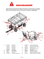
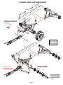
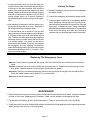
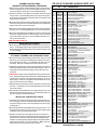
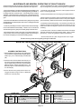
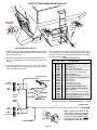
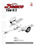
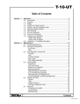
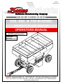
01-04 AG20009, Rev 4 Dethmers Manufacturing Company DOING OUR BEST TO PROVIDE YOU THE BEST 550, 650, & 750 BUSHEL GRAVITY FLOW WAGON OPERATORS MANUAL READ complete manual CAREFULLY BEFORE attempting operation. ASSEMBLY CALIBRATION OPERATION REPLACEMENT PARTS DEMCO Dethmers Mfg. Co. 4010 320th St. P.O. Box 189 Boyden, IA 51234 PH: (712) 725-2311 or (712) 725-2302 Toll Free: 1-800-543-3626 FAX: 1-800-845-6420 www.demco-products.com Page 1 INTRODUCTION Thank you for purchasing a Demco Gravity Flow Wagon. We feel you have made a wise choice and hope you are completely satisfied with your new piece of equipment. Proper care and use will result in many years of service. WARNING: TO AVOID PERSONAL INJURY OR DEATH, OBSERVE FOLLOWING INSTRUCTIONS: Never overload wagon. Do not exceed the rating of the gear or load rating of the tires, whichever is less. Ensure that anybody present is clear before applying power to any machinery used in conjunction with wagon box or when moving box. Never allow anyone in, near, or on gravity box during transporting or unloading of grain. Moving grain is dangerous and can cause entrapment, resulting in severe injury or death by suffocation. Do not exceed 20 miles per hour when towing wagon. GENERAL INFORMATION 3. When placing a parts order, refer to this manual for proper part numbers and place order by PART NO. and DESCRIPTION. 1. Unless otherwise specified, high-strength (grade5) (3 radial-line head markings) hex head bolts are used throughout assembly of this piece of equipment. 4. Read assembly instructions carefully. Study assembly procedures and all illustrations before you begin assembly. Note which parts are used in each step. This unit must be assembled in proper sequence Table of Contents or complications will result. General information ...................................................................................................... 2 Bolt Torque ................................................................................................................... 2 Torque Specifications Safety Sign Locations .................................................................................................. 3 Running Gear Parts Breakdown ................................................................................... 4 Torque figures indicated are Running Gear Parts List and Assembly Instructions ................................................... 5 valid for non-greased or nonBrake Tongue Maintenance and Adjustment ................................................................ 6 oiled threads and heads unless Brake Tongue Parts Breakdown and Parts List ............................................................ 7 otherwise specified. Therefore, 13î Brake Cluster Parts Breakdown and Parts List ..................................................... 8 do not grease or oil bolts or Running Gear Brake Line Parts Breakdown and Assembly Instructions ..................... 9 capscrews unless otherwise Brake System Maintenance and Repair ....................................................................... 10-11 specified in this manual. When Gravity Flow Box Parts Breakdown ............................................................................. 12 using locking elements, Gravity Flow Box Assembly Instructions and Parts List ............................................. 13 increase torque values Maintenance and General Operation ........................................................................... 14 by 5%. *GRADE or CLASS value Gravity Box to Running Gear Assembly Instructions and Parts List ........................... 14 for bolts and capscrews are Gravity Flow Light Kit Parts Breakdown, Parts List, and Wiring Schematic ............... 15 identified by their head 2. Whenever terms "LEFT" and "RIGHT" are used in this manual it means from a position behind wagon box and facing forward. BOLT TORQUE TORQUE DATA FOR STANDARD NUTS, BOLTS, AND CAPSCREWS. Tighten all bolts to torques specified in chart unless otherwise noted. Check tightness of bolts periodically, using bolt chart as guide. Replace hardware with same grade bolt. NOTE: Unless otherwise specified, high-strength Grade 5 hex bolts are used throughout assembly of equipment. Bolt Torque for Metric bolts * ìAî 6 7 8 10 12 14 16 18 20 22 24 CLASS 8.8 lb-ft (N.m) 9 (13) 15 (21) 23 (31) 45 (61) 78 (106) 125 (169) 194 (263) 268 (363) 378 (513) 516 (699) 654 (886) CLASS 9.8 CLASS 10.9 lb-ft (N.m) lb-ft (N.m) 10 (14) 13 (17) 18 (24) 21 (29) 25 (34) 31 (42) 50 (68) 61 (83) 88 (118) 106 (144) 140 (189) 170 (230) 216 (293) 263 (357) --364 (493) --515 (689) --702 (952) --890 (1206) markings. GRADE-2 GRADE-5 GRADE-8 Bolt Torque for Standard bolts * CLASS 10.9 10.9 CLASS 9.8 9.8 CLASS 8.8 8.8 Page 2 A 1/4 5/16 3/8 7/16 1/2 9/16 5/8 3/4 7/8 1 GRADE 2 lb-ft (N.m) lb-ft 6 10 20 30 45 70 95 165 170 225 (8) (13) (27) (40) (60) (95) (130) (225) (230) (300) 9 18 30 50 75 115 150 290 420 630 GRADE 5GRADE 8 (N.m) lb-ft (N.m) (12) (25) (40) (70) (100) (155) (200) (390) (570) (850) 12 (16) 25 (35) 45 (60) 80 (110) 115 (155) 165 (220) 225 (300) 400 (540) 650 (880) 970 -(1310) SAFETY SIGN LOCATIONS Types of safety sign and locations on equipment are shown in illustration below. Good safety requires that you familiarize yourself with various safety signs, type of warning, and area or particular function related to that area, that requires your SAFETY AWARENESS. J E C A K B D E F G J I C H I M B F C J A B C D E AG21045 AG21047 AG21017 AG21025 AG21018 AG21026 AG21067 04508 AG21068 AG21030 550 yellow 550 off white 650 yellow 650 off white 750 yellow 750 off white Keep off ladder Amber reflector Just 4 Kids Left mirage stripe (Qty. 3) L A L F G H I J K L M Page 3 AG21019 AG21027 AG21070 AG21002 AG21031 04804 AG21020 AG21028 07278 AA21028 D Demco (medium) yellow Demco (medium) off white Attention Do not turn sharply Caution 20 M.P.H. Right mirage stripe (Qty.3) Red reflector Large Demco (yellow) Large Demco (off white) Conspicuity (with white to the top) Manual inside(on plastic canister) RUNNING GEAR PARTS BREAKDOWN 37-5/16 41-3/8 41-5/16 B D S D N F N O Q INVERT PLATE Q AS SHOWN TO LOWER PROFILE WHEN USED ON 750 BU. GEAR E A O E Y Q J C P M G M P 35 L R X T K W H 8 W ?-10 = Red ?-15 = Yellow ?-20 = Green ?-56 = Off-White V I 31 29 34 25 28 24 33 36 32 29 30 27 8 23 14 *13 For Breakdown of Tongue and Pivot Arm Assembly See Page 15 16 36 15 17 30 *13 14 18 9 19 24 22 22 34 OPTIONAL FRONT WHEEL BRAKES ON 550 BUSHEL 26 20 21 18 16 23 *13 14 17 36 15 12 14 9 *13 10 8 11 76 4 Page 4 53 13 1 2 WHEEL HUB ASSEMBLY (5181) FOR 550 BU. HAS POUND IN CAP INSTEAD OF BOLT ON CAP WITH GASKET RUNNING GEAR PARTS LIST REF. NO. PART NO. 5474 QTY. 4 DESCRIPTION Wheel Hub Assembly (650 & 750 BU.) 1. 2. 3. 4. 5. 6. 7. 8. 9. 10. 11. 12. 13. 04305 07362 07353 05088 07354 07358 07360 07435 07861 07357 07359 07361 09532 4 1 1 1 1 1 1 10 1 1 1 1 1 5/16-18 UNC x 1/2 Hex Head Bolt Gr. 5 Hub Cap 1-1/4"-12 UNF Castle Nut 7/32" x 2" Lg. Cotter Pin 1.32" I.D. x 3.00" O.D. Flatwasher Outer Cone Bearing (460) Outer Cup (453A) 3/4" Flanged Wheel Nut 10 Bolt Hub (W871) (NOT SOLD SEPERATELY) 3/4"-16 UNF Stud Bolt (replacement) Inner Cone Bearing (39585) Inner Cup (39520) Oil Seal (CR30087) Gasket 5181 4 2. 3. 4. 5. 6. 7. 8. 9. 10. 11. 12. 01933 01934 01935 01936 01937 01938 09240 10151 01942 01943 01944 1 1 1 1 1 1 8 1 1 1 1 Hub Cap (NOT SHOWN) 1"-14 UNF Castle Nut 3/16" x 2-1/2" Lg. Cotter Pin 1-1/16" I.D. x 2-1/8" O.D. Flatwasher Outer Cone Bearing Outer Cup 5/8-18 UNF Wheel Nut, Beveled 8 Bolt Hub (NOT SOLD SEPERATELY) 5/8-18 UNF Stud Bolt (replacement) Inner Cone Bearing Inner Cup Oil Seal *13. *13. 5182 5183 2 2 Tie Rod End w/Left Hand Threads Tie Rod End w/Right Hand Threads *13. *13. 07420 07421 2 2 Tie Rod End w/Left Hand Threads (750 bu.) Tie Rod End w/Right Hand Threads (750 bu.) 14. 15. 16. 17. 18. 19. 20. 21. 22. 23. 24. 25. 26. 27. 28. 29. 30. 31. 32. 33. 34. 35. 36. 01948 01949 07411 07412 07324 03532 05031 02010 07910 07911 01953-30 07407 01922 01923 01951 07382-? 07410-? 09033-? 07737-? 07364-? 07409-? 07736-? 07363-? 07408-? 07366-? 07393-? 01965-30 01964 02961 01966-? 07738-? 07367-? 07394-? 00152 07356 03908-? 04909-? 00084 2 2 2 2 4 2-4 16 16 1 1 1 1 3 3 2 2 2 2 1 1 1 1 1 1 1 1 1 2 2 1 1 1 1 16 2 4 4 16 ASSEMBLY INSTRUCTIONS MOUNTING THE WHEELS, AND ASSEMBLING THE FRONT AND REAR BOLSTER FRAMES 1. Insert the Lock Collar (A) into the opening provided on the Front Bolster Reach Pipe Frame (C). The end of the Reach Pipe (B) with a hole 41-5/16" from the end should slide into the Front Bolster Frame (C). Line up the holes in the Lock Collar and bolt together using one 3/4" x 7" bolt (D) and one 3/4" nylon locknut (E). 2. Insert the Reach Pipe (B) with the hole 37-5/16" from the end into the Rear Bolster Reach Pipe Frame (F) and bolt together using one 3/4" x 7" bolt (D) and one 3/4" nylon locknut (E). 3. Mount the Tire and Rim (G) to the front and rear bolster using forty 3/4" Flanged Wheel Nuts (H) (650 & 750 Bu. only). For 550 Bu. mount using 32 Lug Bolts. Wheel Hub Assembly (550 BU.) 1"-14UNF Jam Nut w/Left Hand Thread 1"-14UNF Jam Nut w/Right Hand Thread 1.25-12UNF Jam Nut w/Left Hand Thread (750 bu.) 1.25"-12UNF Jam Nut w/Right Hand Thread (750 bu.) 13" Brake Drum (650 & 750 Bu.) 13" Brake Drum (550 Bu.) (4 whl. brakes optional) 1/2"-20UNFx1-1/4" Bolt Gr.5 (750 /650Qty.24) 1/2"-20UNF x 1" Hex Head Bolt Gr. 5 Left Brake Cluster (shown) Right Brake Cluster (not shown) Pivot Arm Mtg. Pin (550 & 650 bu.) Pivot Arm Mtg. Pin (750 bu.) Special 1-1/2"-12UNF Hex Nut 1/4"-20UNC x 1/4" Socket Set Screw 1-1/2" I.D. x 1-7/8" O.D. x 2" Bronze Bushing Tie Rod (550 & 650 bu.) Tie Rod (750 bu.) 2 Dia. Spindle Mounting Pin Right Front Spindle (550 bushel) Right Front Spindle (650 bushel) Right Front Spindle (750 bushel) Left Front Spindle (550 bushel) Left Front Spindle (650 bushel) Left Front Spindle (750 bushel) Front Bolster Frame (550 and 650 bu.) Front Bolster Frame (750 bushel) 4-1/2" O.D. Collar 3/4"-10UNC x 7" Hex Head Bolt Gr. 5 3/4"-10UNC Nylon Insert Locknut 4" O.D. Reach Pipe Rear Bolster Frame (550 bushel) Rear Bolster Frame (650 bushel) Rear Bolster Frame (750 bushel) 1/2"-20 UNF Hex Nut Thrust Bearing 22.5 x 13.5 10 Bolt Rim (650 & 750 Bu.) 22.5 x 8.25 8 Bolt Rim (550 Bu. only) 1/2" Lockwasher TIGHTEN ALL BOLTS (SEE TORQUE CHART ON PAGE 2.) INSTALLING THE TONGUE AND THE LIFT ASSIST SPRING 1. Mount the Tongue (I) onto the pivot arm (R), fasten together using one 1-1/2" Dia. x 9" bolt (J) and one 1-1/2" nut (K). Tighten just enough to take out all slack and hold nut in place using one 1/4" x 1/4" socket set screw (L). 2. Insert 5/8-11 x 9 bolt through tongue as shown using two 5/8 Flatwashers (W), and one 5/8 nylon insert locknut (X). Tighten bolt until all slack is removed between the tongue and pivot arm (R). Do not overtighten, the tongue should still move freely. Raise the tongue and support on a stand. 3. Mount the Lift Assist Plate (Q) through the Steering Stop (Y) onto the top of the Pivot Arm (R) using two 5/8-11 x 1-3/4 bolts (S) and two 5/8 nylon insert locknuts (T). Plate must be inverted when installed on the 750 bushel box (see note on illustration.) 4. Attach the Lift Assist Springs (M) to the Lift Assist Plate(Q) by threading the two 1/2-13 x 6 full thread bolts(N) with 1/2 lockwasher(O) into the threaded insert in the springs(O). Tighten the bolts to remove any slack. Remove the stand and adjust the tongue height using the two 1/2 x 6 bolts. ADJUSTING THE TIE RODS FOR ALIGNMENT 1. Alignment is preset at the factory. To check alignment, the Tie Rods (P) should be adjusted to have 1/4" to 3/8" toe in (measured at tire bead edge of rim). When this adjustment is made, the tongue must be aligned with the reach pipe. Be sure both wheels toe in equally. Please order replacement parts by PART NO., DESCRIPTION and COLOR. Page 5 * This kit includes tie rod end (specify left or right hand threads), grease zerk, rubber cup, cotter pin, castle nut, and flat washer. NOTE: Parts Listed for 550, 650 & 750 Bu. Wagons. DEMCO BRAKE TONGUE MAINTENANCE AND ADJUSTMENT WARNING: Review all of the following instructions before installation and use of the hydraulic brake tongue. Dealers or Distributors must review these instructions with the ultimate user. Failure to follow these instructions, or failure to properly maintain the braking system after installation, can result in loss of braking action which could cause severe property damage, personal injury and/or death. DISASSEMBLY AND REASSEMBLY 1. The brake tongue is preassembled and adjusted at the factory: Do Not Disassemble or Attempt to Adjust CAUTION The Tongue Push-Rod Assembly (#11) To disassemble the tongue: (refer to illustration on page 15) A. Remove 3/4bolts (#8) , remove stop block (#7), and pull male tongue (#30) out of female tongue (#1). B. Remove 1/2bolt (#4), pin (#25), and spacer (#27) C. Remove set screw (#24) from adjustment spud (#23b), unthread and remove adjustment spud (#23b). D. Remove push-off assembly (#28), pin (#29), two shocks (#26), and two springs (#10). E. To remove tongue push-rod assembly (#11), master cylinder (#2), emergency lever (#14), pin (#15), spring (#16), and guide (#17), refer to section a&b of ìServicing the Emergency Leverîon this page. To reassemble the tongue: (refer to illustration on page 15) A. Replace 2 shocks (#26) into yoke (#28), with pin (29). B. Place 2 springs (#10), onto shaft of push-off assembly (#28), and insert shaft into female tongue (#1), through hole in plate (shown in exploded view). C. Thread adjustment spud (#23b) onto rear threaded portion of push-rod assembly (#28), until the 2 springs (#10) compress to a length of 6-1/2. Install and tighten set screw (#24), using Locktite, into one of the threaded holes of the spud (23b). D. Insert pin (#25) into hole in tongue, through 1 shock (#26), through the spacer (#27), and through the other shock (#26) and tongue. Install and tighten 1/2 bolt, lockwasher, and washer (# 4,5,6). E. Install master cylinder (#2), (refer to c-f of Servicing Emergency Lever section on this page). F. Thread adjust spud (23a) onto front threaded portion of push-rod assembly (#28). Insert male tongue (#30), (with latch installed as shown), into female tongue (#1). Install stop block (#7), using 3/4 bolts and lockwashers (#8, #9). Pull male tongue (#30) forward to latched position and adjust spud (#23a) until there is a 3/16 gap between spud (#23a) and rear stop surface of male tongue (#30) see arrow. G. Tighten set screw (#24),using Locktite, into hole in spud (#23a). 2. Connect and tighten all brake lines. 3. Fill the Master Cylinder (#2) with DOT 3 or 4 brake fluid. 4. Bleed the brake system using a pressure-type brake bleeder or manually, as follows: a. Remove the two Self-Tapping Screws (#18) and LockWashers (#19) that hold the Lever Guide (#17) and the flat Emergency Lever Spring (#16). Remove the Lever Guide and the Emergency Lever Spring. Using short strokes, pull forward on the Emergency Lever (#14), pumping the Master Cylinder until the brake fluid within the Master Cylinder stops bubbling. b. Attach a bleeder hose to the bleeder valve on one of the wheels (always begin with wheel farthest from the master cylinder and move toward it). Immerse the other end of the hose into a clean, transparent container partially filled with brake fluid. Loosen the bleeder valve one turn and, watching the hose in the transparent container, use the Emergency Lever to pump the Master Cylinder as long as air bubbles continue to leave the hose. When the bubbles stop, close the bleeder valve, move to the next wheel, and repeat the process until all the brakes have been bled. (Note: Check the fluid level in the Master Cylinder frequently while bleeding the brakes (every 4 or 5 strokes). Refill as necessary to keep the level above half full.) 5. Once bleeding is completed, refill the Master Cylinder and attach the Cap (#20) securely. Replace Emergency Lever Spring, Lever Guide, with Lock Washers and Self-Tapping Screws. 6. Test the brakes by pulling the Emergency Lever (#14) forward until it locks into its first detent position. (The lever should be approximately straight up.) Attempt to rotate the wheels in a forward direction. If any of the wheels rotate, the brakes must be adjusted on that wheel. To adjust the brakes, release the Emer gency Lever from its locked position and set the wheel brake adjustment up 2 or 3 notches (refer to instructions on page 18). Repeat the test procedure as necessary. MAINTENANCE 1. Frequently check the brake fluid level. (Fluid must be approved, clean and uncontaminated.) 2. Inspect the brake tongue and brakes and replace bent, worn or damaged parts. 3. Be constantly aware of the system's braking quality and make periodic checks. Consult a certified brake specialist to make the necessary adjustments and/or repairs. Failure to do so could result in loss of braking. SERVICING THE EMERGENCY LEVER If the Emergency Lever (#14) of the tongue is applied, it can be disengaged by using a screwdriver to lift upward on the front of the flat Emergency Lever Spring (#16) while pulling the lever forward until it releases. A thorough inspection of the Emergency Lever, Emergency Lever Spring, and the Chain with S-Hooks is required and all damaged parts must be replaced as follows: a. Remove the Master Cylinder (#2) and the Push Plate Assembly (#11). Be careful not to get dirt into the Master Cylinder. (A new Master Cylinder Gasket (#3) should be used when reinstalling.) b. Remove the Safety Chain from the Emergency Lever (#14), Emergency Lever Guide (#17), and flat Emergency Lever Spring (#16), then pull the lever out of the tongue (#1) from the bottom. c. Install the new Emergency Lever from the bottom of , and up through the slot in, the tongue. Attach the new Emergency Lever Spring, and the Emergency Lever Guide. d. Install a new Master Cylinder Gasket to the Master Cylinder and put the Push Plate Assembly and Master Cylinder back into the inside of the tongue. e. Squeeze shut the S-Hook of the Emergency Chain (#13) onto the Emergency Lever (#14). f. Add adequate brake fluid to the Master Cylinder and bleed the brake system per instructions 4-6 in the disassembly and reassembly section. Page 6 47 BRAKE TONGUE ASSEMBLY 47 48 48 53 53 ?-10 = Red ?-20 = Green 46 550 & 650 BU. GEAR 46 52 750 BU. GEAR ONLY 43 THIS PLATE IS WELDED INTO TONGUE (#1) - SHOWN SEPARATE FOR CLARITY 49 6 34 33 32 USE LOCKTITE ON SET 24 SCREW 35 23 27 19 17 10 10 28 38 13 SOLD AS ASSEMBLY ONLY (5628-?) TONGUE ASSEMBLY PARTS LIST 1. 2. 3. 4. 5. 6. 7. 8. 9. 10. 11. 12. 13. 14. 15. 16. 17. 18. 19. 20. 21. 22. 23. 24. 25. 26. 27. 28. 29. 30. 09292-? 05680 05681 04795 00084 00085 09308-30 05047 00254 05952 09307 SB12098 09309 05951 05694 05693-95 03866-95 02196 05424 03876 03877 05849 01076 00057 09337 01923 09325-95 SB12426 09323 09305 09324 09293-? 1 1 2 2 2 1 2 2 2 1 1 1 1 1 1 1 2 2 1 4 4 2 3 1 2 1 1 1 1 3 42 65 7 11 41 15 1 37 REF. PART NO. NO. QTY. 20 38 39 22 41 21 18 29 23 51 45 ZERK LOCATED ON OPPOSITE SIDE OF THIS GUSSET 16 14 36 30 44 45 25 26 5 50 24 MALE TONGUE STOP 4 54 24 USE LOCKTITE ON SET SCREW 31 50 31. 32. 33. 34. 35. 36. 37. 38. 39. 40. 41. 42. 43. 44. 9 8 DESCRIPTION Adjustable Tongue-Female Half for Brakes Master Cylinder w/ 05681 Gasket Inc'd Master Cylinder Gasket (Inc'd in 05680) 1/2-13 UNC x 1" Gr.5 Bolt 1/2" Lockwasher 1/2" Flatwasher Male Tongue Stop Block 3/4-10 UNC x 2-1/2 Gr. 5 Bolt 3/4 Lockwasher Spring Push Plate Assembly Orfice Connector for Master Cyl. 72" Safety Chain Emergency Lever Groove Pin Emergency Lever Spring Emergency Lever Guide 5/16" -18 UNC x 3/4" Self Tapping Screw 5/16" External Tooth Lock Washer Mast. Cyl. Cap w/ diaphragm & O-ring Diaphragm Replacement O-ring Replacement 1/4"-20 UNC x 3/4 Gr.5 Bolt 1/4" Lock Washer Adjustment Spud 1/4" x 1/4" Socket Set Screw Rear Shock Pin Shock Dampner Rear Shock Pin Spacer Push-off Assembly Front Shock Pin Adjustable Tongue-Male Half 40 4 2 12 07517-30 01158-95 07521-95 00036 01263 09317 00640 04642 02587 05687 00477 04835 01953-30 01922 1 1 1 1 1 1 1 2 1 1 2 1 1 1 Tongue Extension Latch Latch Spring Latch Pin 5-16 Lockwasher 5/16-18 UNC x 3/4 Hex Head Bolt Gr.5 1/2-13 x 2 Eye Bolt 1/2-13 Jam Nut 1/4-28 UNF Grease Zerk 5/8-11 Nylon Insert Locknut Master Cylinder Protective Boot 5/8 Flatwasher 5/8-11 UNC x 9 Hex Head Bolt Tongue Mtg. Pin Special 1-1/2-12 UNF Hex Nut REF. PART NO. NO. QTY. (Not Included in 5628-?) DESCRIPTION 45. 00306-30 2 Lift Assist Springs 46. 09326-30 1 Upper Lift Assist Plate (550 & 650 Bushel) - 10158-30 1 Upper Lift Assist Plate & Steer Stop (750) 47. 04058 2 5/8 - 11 UNC x 2-1/2 Grade 5 Bolt 48. 00545 2 1/2 - 13 UNC x 6 Full Thread Bolt 49. 01954-? 1 Pivot Arm (550-650 Bushel) - 07406-? 1 Pivot Arm (750 Bushel) 50. 01951 2 Bronze Bushing 51. 05395 1 45 Grease Zerk 52. 09607-30 1 Steering Stop (550 & 650 only) 53. 00085 2 1/2 Flatwasher 54. 02587 2 5/8 - 11 Nylon Insert Locknut Please order replacement parts by PART NO. and DESCRIPTION. Page 7 KIT NUMBERS 40 - 5398 - Master Cylinder Repair Kit w/gasket 13" UNI-SERVO BRAKE CLUSTER PARTS BREAKDOWN 6 7 15 1 8 4 5 2 15 3 9 2 12 14 12 10 10 11 13 10 11 10 BRAKE CLUSTER PARTS LIST REF. PART NO. NO. QTY. 07911 07910 1. 03529-30 1 2. 5509 1 3. SB9776 1 SB9777 1 4. SB9783 1 5. SB9254 2 6. 05961 2 7. 05424 2 8. 05431 1 DESCRIPTION Right Hand Cluster (shown) Left Hand Cluster Back Plate Assembly Brake Shoe Kit (2 Front & 2 Rear) Wheel Cylinder Assembly - Right ( shown) Wheel Cylinder Assembly - Left Push Rod Cover Plate - Adjusting Hole 5/16"-18UNC x 5/8" Hex Head Bolt 5/16" External Tooth Washer Bleeder - Replacement 9. SB10961-95 1 10. SB9789 4 11. 05983 2 12. SB9786 2 13. SB23324 1 14. SB24765 1 15. SB9788 2 - 1 Wheel Cylinder Repair Kit (includes spring, cup and boot) Please order replacement parts by PART NO. and DESCRIPTION. Page 8 SB15845 Shoe Guide Cup - Shoe Hold Down Spring - Shoe Hold Down Spring - Shoe Adjusting Screw Assembly Spring - Adjusting Screw #6 Hold Down Pin RUNNING GEAR BRAKE LINE PARTS BREAKDOWN Note: Front brakes are optional on the 550 bushel running gear. 9 10 13 10 10 10 10 4 10 10 9 12 11 14 BRAKE LINE PARTS LIST 10 7 8 10 3 5 13 4 10 2 9 6 1 REF. PART NO. NO. QTY. DESCRIPTION 1. 05979 1 #6 x 52 Rubber Line *2. SB7900 1 Brake Tee *3. SB508 1 3/16" x 8" Steel Brake Line *4. SB7785 2 Brass Tee *5. SB520 1 3/16" x 20" Steel Brake Line *6. SB541 1 3/16" x 41" Steel Brake Line *7. 05982 2 18" Rubber Brake Hose *8. SB7764 2 Rubber Brake Line Clip 9. SB553 3 3/16" x 53" Lg. Steel Line 10. 02549 10 Rubber Protector (for steel lines) 11. SB13H66 1 Lg. Rubber Line w/ solid F. end (2x) 12. SB580 1 3/16" x 80" Steel Brake Line 13. 02802 2 5/16"-18 UNC Nylon Insert Locknut 14. B64 H 1 Hose Clamp 8 7 1. Assemble the running gear. 2. Mount the Rear Brass Tee (#4) onto the bolt welded to the top of the rear bolster frame using one 5/16" nylon insert locknut (#13). Please order replacement parts by PART NO. and DESCRIPTION * Optional front brakes on 550 bushel wagon. 3. Next attach the 52" Rubber Line (#1) to the orifice fitting on the master cylinder (see page 8). 4. Attach Brake Tee (#2) to the 52" Rubber Brake Hose(#2). Attach the 53" Steel Brake Line (#9) to the Brake Tee (#2), and bend the 53" Steel Line (#9) around the front bolster frame to fit (as shown). 6. Assemble 53" Rear Steel Lines (#9) to the brake cluster first. Then bend around the top of the rear bolster frame and attach to the Rear Brass Tee (#4) as shown. Now attach 80" Steel Lines (#12) to center of outlet on Brass Tee (#4) along reach pipe. NOTE: When bending steel lines, form around a 3/4" diameter pin, 7. Assemble 12" Rubber Line (#11) between the 80" Steel Line (#12), be careful not to make the bend too sharp or line failure will occur. and the 53" Steel Front Brake Line (#9) allowing some slack. Hold 80" line in place with clamp (#14). 5. Attach 8" Steel Brake Line (#3) to Brake Tee (#2), and to Brass Tee (#4). Attach 20" and 41" Steel Brake Lines (#5 & #6) to Brass Tee 8. Put Rubber Line Protectors (#10) around steel lines at clips and bend (#4). Attach 18" Rubber Brake Hose (#7) to lines #5 and #6 and to clips down. Front Brake Clusters (Refer To Diagram Above). Now attach the rubber Brake Line Clips (#8). Page 9 WARNING: To Prevent Serious Injury or Death Saltwater, granular fertilizers and other corrosive materials are destructive to metal. To prolong the life of a braking system used under corrosive conditions, we recommend that the actuator be flushed periodically with a high pressure water hose. Be sure to re-grease bearings and oil all moving parts after the unit has dried. At the end of the season, when unit is to be stored, remove the brake drums and clean inside the brakes. Pack wheel bearings before drum is installed. Backplate Installation Brake Adjustment Mount the backplate to the spindle flange. In mounting the brake, be sure the hydraulic wheel cylinder is at the top. Brakes are also marked as RIGHT and LEFT. The brake designated as LEFT travels on the driverís side of the road. Before removing the ground stand jacks, adjust the brakes. Uni-servo brakes must be adjusted periodically to assure having brakes when they are applied. Insert a brake adjusting tool or a screwdriver into the slotted hole. With the handle up and the bit down and against the adjusting nut, pull down on the handle. While spinning the wheel adjust the cog wheel up until you cannot rotate the wheel forward. Then back off the adjusting wheel twenty notches. Brake Line Installation Use care in forming tubing to avoid sharp bends or kinks. Use double flare steel tubing to assure tight leakproof connections. This must be done by a certified brake shop. Anchor all hydraulic lines at two foot intervals to prevent chafing and vibration. Use hydraulic rubber hose at points of flexing. Anchor hose ends to avoid stress on tubing. ALWAYS ROTATE DRUM IN DIRECTION OF FORWARD ROTATION ONLY. Brake Drum Maintenance Brake drums must be reground if abnormal wear is found, such as brake shoe hitting brake drum once lining is gone, rivets hitting brake drums and or brake drums out of round. NOTE: Maximum diameter allowed 13.060" Brake Set-up WRONG 1. Attach brake line to master cylinder outlet. Make sure all connections are tight. 2. Fill the master cylinder from a sealed container of DOT 3 or 4 brake fluid. A pressure type brake bleeder may be used. If one is not available, you can bleed the system manually as follows. RIGHT (Double Flare) 3. After the master cylinder has been filled, remove the flat spring behind the emergency lever. Pull forward on the lever to pump the master cylinder. Use short strokes until bubbling stops in the master cylinder. Bleed the rear axle first. Install bleeder hose on the bleeder valve on the first wheel with other end of the hose in a clear container partially filled with brake fluid. Page 10 Loosen the bleeder valve one turn and pump the master cylinder until the air bubbles stop coming out of the hose in the glass container, then close the bleeder valve and repeat the process on the other wheels. (Watch the fluid level in the master cylinder and refill so level does not fall below 1/2 full). Refill master cylinder every 4 or 5 strokes. Dispose of contaminated brake fluid according to local regulations. 4. After bleeding is completed, refill the master cylinder and put the filler cap on securely . Replace the flat spring behind the emergency lever. To test the brakes use a wrench or vise grip and clamp onto the top of the emergency lever to lengthen it. Pull lever forward until lever locks on the second click. The lever should be approximately straight up and down. Now try to rotate each of the four wheels in a forward rotation. You should not be able to rotate the wheels forward. If you can, then release the emergency lever by wedging a screwdriver under the flat spring behind the lever and set each wheel brake adjustment up 2 or 3 notches. Then repeat the test procedure. Hitching The Wagon 5. Be sure Pin and hitch rating is equal to or greater than the wagon GVWR. 6. Connect the emergency chain hook to towing vehicle. 7. If the emergency brake lever is accidentally applied while unhitching, release the lever by pulling it forward and with a screwdriver lift up the front of the flat spring until it releases the lever. Many times these parts are damaged when this happens. An inspection of the lever, flat spring, and chain with S-hooks is required and any damaged parts must be replaced. Replacing The Emergency Lever Step one: Remove the lever guide and flat spring. Take the S-hook off the lever, take the lever out from the inside. Step two: Install the new lever from the inside and up through the slot. Replace the new flat spring and the lever guide. Replace the push rod and master cylinder and new gasket. Step three: Take the new chain and fasten the S-hook to the lever by squeezing the hook shut with a pliers. Check the master cylinder and fill with DOT 3 or 4 brake fluid. Step four: Re-bleed brake system. MAINTENANCE 1. Before towing check to be sure master cylinder is full of brake fluid and check lines for leaks. Inspect the actuator for bent or worn parts. Replace parts if necessary. Make sure the actuator mounting bolts are tight. 2. Periodically check braking quality, as described above. Failure to do so can result in loss of braking. 3. If units are used in corrosive conditions the actuator and wheels should be washed out with high pressure water. When actuator parts are dry, oil all moving parts. Page 11 550, 650 & 750 BUSHEL WAGON PARTS BREAKDOWN 26 43 27 45 26 ?-10 = Red ?-20 = JD Green 45 44 27 41 39 8 40 8 10 42 45 33 10 34 38 40 27 8 45 34 26 32 38 10 26 40 45 41 36 38 27 36 37 8 37 35 10 47 48 46 8 22 34 26 8 10 54 27 55 33 24 10 56 8 8 8 8 25 53 20 10 19 20 50 21 28 8 23 45 51 49 29 30 8 5184 DOOR LIFT ASSEMBLY 7 14 16 6 9 5 12 18 13 11 18 17 8 15 5 12 13 14 16 6 9 4 3 16 9 9 1 10 11 50 27 9 8 31 7 19 10 52 57 22 8 27 26 55 10 10 Page 12 2 15 4 3 16 9 8 ASSEMBLY INSTRUCTIONS MOUNTING THE SIDE BRACES, EXTENSIONS 1. Mount the Front, Back, and Side Extensions (#41 & 39) loosely to the box using twenty-two 5/16" x 3/4" bolts (#26), twenty-two 5/16" nylon locknuts (#27), and forty-four 5/16 flatwashers (#45). 2. Mount the Outside Corner (#42) to the outside of the extensions using six 5/16" x 3/4" bolts (#26) and six 5/16" nylon locknut (#27). The bottom two bolts must also hold the Inside Corner (#44) on the inside of the box as shown. 3. Mount the Corner Filler Cap (#43) under the lip on the outside of the extensions using two 5/16" x 3/4" bolts (#26) two 5/16" flatwashers (#45) and two 5/16" nylon locknuts (#27). 4. Mount the inside Angle Braces (#35) to the inside of the box as shown using six 1/2" x 1-1/4" bolts (#36) and six 1/2" nylon locknuts (#37). 5. Mount the inside Side Braces (#38 & 40) to the box (#32) and side extensions (#39) with back up washers (#34) on the outside as shown using twenty-four 3/8" x 1-1/4" bolts (#8) and twenty-four 3/8" nylon locknuts (#10). NOW TIGHTEN ALL BOLTS. MOUNTING THE LADDERS 1. Mount the top of the ladders (#33) to the gravity flow box using four 3/8" x 1-1/4" bolts (#8) and four 3/8" nylon locknuts (#10) as shown. Bolt the bottom of the ladders (#33) to the subframe using two 3/8" x 1-1/4" bolts (#8). INSTALLING THE BOX, DOOR LIFT CHANNEL, DOOR LIFT WHEEL ASSEMBLY AND TRANSPORT CHAIN 1. Mount the Door Lift Channel (#22), with the roller chain to your left side when you are facing the unloading side of gravity box, to the Door (#23) using four 3/8" x 1-1/4" bolts (#8), four 3/8" nylon locknuts (#10). Place the unloading door into the rails of the box. 2. Slide the door lift wheel mount (Sub. Assembly #5184) over the door lift channels (#22) and bolt it to the gravity box using four 3/8" x 1-1/ 4 bolts (#8), four 3/8" flatwashers (#9), and four 3/8" nylon lock nuts (#10). 3. IMPORTANT Tighten all mounting bolts just enough to limit movement. Adjust by raising and lowering the door, after final adjustment counter sink set screws in sprocket holes by drilling 1/16" to 1/8" deep using a 1/4" drill bit. Then tighten bolts and setscrews accordingly to prevent the door from binding. 4. Bolt the transport chain (#49) to the door lift wheel mount (#1) using one 5/16 x 1" bolt (#52), one 5/16" flatwasher (#45), and one 5/16" nylon locknut (#27). 5. Mount the Door Lift Wheel Mount Cover (#18) using two 1/4" x 3/4" slotted truss head bolts (#19) and two 1/4" lockwashers (#20). Adjust cover so door lock will work properly. INSTALLING THE DELIVERY CHUTE 1. Assembly of the chute should be done after mounting the box on the running gear. Mount the Chute Brackets (#24 & 25) to the grav ity flow box using two 5/16" x 3/4" bolts (#26) and two 5/16" nylon locknuts (#27). 2. Mount the Unloading Chute (#28) to the box using two 3/8" x 1-1/4" bolts (#8) and two 3/8" nylon lock nuts (#10). When tightening be certain the chute moves up and down freely. 3. Slide the Center Dump Chute (#29) under the box, hook the "L" shaped brackets over the rods extending from the frame to the under side of the box. Raise the center dump chute and align hinges. Slide the Center Dump Pins (#30) through the hinges and hold in place using three 3/32" x 3/4" cotter pins (#31). Note: Check all bolts and nuts to ensure proper tension or torque. Page 13 550, 650 & 750 BUSHEL WAGON PARTS LIST REF. NO. PART NO. QTY. 5184-30 DESCRIPTION Door Lift Assembly 1. 2. 3. 4. 5. 6. 7. 8. 9. 10. 11. 12. 13. 14. 15. 16. 17. --18. -- 02025-30 02024-30 09552-95 01115 01114 01243-30 00082 00907 00059 02592 02023 01332-30 02849 02028 02026 00789 04976 04975 04829 03096 04642 1 1 2 2 2 2 2 2 6 4 2 2 2 2 2 4 1 1 2 2 6 Door Lift Wheel Mount Door Lift Wheel 2" O.D. x 3/8" I.D. Washer 1-1/4" O.D. x 3/4" I.D. Bushing 3/4" O.D. x 3/8" I.D. Bushing Roller Brace Bracket 3/8"-16UNC x 2-1/2" Hex Head Bolt Gr.5 3/8"-16UNC x 1" Hex Head Bolt Gr.5 3/8" Flatwasher 3/8"-16UNC Nylon Insert Locknut 3/4" Dia. x 4-1/4" Lg. Pin 9 Tooth Sprocket 5/16" x 1-3/8" Roll Pin 10 Tooth Sprocket 20 Tooth Sprocket 3/8"-16UNC x 3/8" Socket Set Screw 109 Links and Connecting Link (#40 chain) 95 Links and Connecting Link (#40 chain) #40 Connecting Link 1/4" x 1-1/4" Roll Pin 1/4 Grease Zerk (not shown) 8. 9. 10. 19. 20. 21. 22. 23. 24. 25. 26. 27. 28. 29. 30. 31. 32. 33. 34. 35. 36. 37. 38. 39. 40. 41. 42. 43. 44. 45. 46. 47. 48. 49. 50. 51. 52. 53. 54. 55. 56. 57. 00523 00059 02592 01906 00057 02030-30 01108-30 02021-? 05257-30 02017-30 01263 02802 02018-30 07733-30 02019-30 02020-95 01092 07369-? 02015-30 01106-30 07373-30 00967 02178 07371-30 07739-30 02012-30 07390-30 07372-30 07740-30 07370-30 07391-30 07741-30 02045-30 07433-30 01105-30 01104-30 00004 07276 07310 07441-30 02022 00214 02990 10241 10242 04055 02772 10277 00092 46 4 46 2 2 1 2 1 1 1 70 71 1 1 3 3 1 2 12 3 6 6 3 2 2 2 3 2 2 2 4 4 4 4 4 69 2-4 2-4 2 1 2 1 1 1 2 4 1 2 3/8"-16UNC x 1-1/4" Hex Head Bolt Gr.5 3/8" Flatwasher 3/8"-16UNC Nylon Insert Locknut 1/4"-20UNC x 3/4" Slotted Truss Head Bolt 1/4" Lockwasher Door Lift Wheel Mount Cover Door Lift Channel Unloading Door Right Chute Deflector Bracket Left Chute Deflector Bracket 5/16"-18UNC x 3/4" Hex Head Bolt Gr.5 5/16"-18UNC Nylon Insert Locknut Unloading Chute Short Unloading Chute (Optional) Center Dump Chute Center Dump Pin 3/32" x 3/4" Cotter Pin Gravity Flow Box Ladder Extension and Box Washer Inside Box Cross Brace - 57-3/4" 1/2"-13UNC x 1-1/4" Hex Head Bolt Gr. 5 1/2"-13UNC Nylon Insert Locknut Box Brace Bar - 113-1/2" Side Extension - 187" (550 bu.) Side Extension - 187" (650 bu.) Side Extension - 187" (750 bu.) Extension Brace Bar - 108-3/4" Front and Back Extension - 109" (550 bu.) Front and Back Extension - 109" (650 bu.) Front and Back Extension - 109" (750 bu.) Outside Corner - 5-1/2" (550 bu.) Outside Corner - 13-1/2" (650 bu.) Outside Corner - 23-1/2" (750 bu.) Corner Filler Cap Inside Corner 5/16" Flatwasher Window (550 Bu. has 2, 650-750 Bu. has 4) Rubber Window Seal (33-1/2" long) Extension Ladder for 750 Wagon Chute Transport Chain 1/4" Flatwasher 5/16"-18 UNC x 1" Hex Head Bolt Gr. 5 Operators Manual Cannister Cannister Bracket 1/4"-13 UNC x 1" Hex Head Bolt Gr. 5 1/4"-13 UNC Nylon Insert Locknut Electrical Plug Holder 1/4"-13 UNC x 1/2" Hex Head Bolt Gr. 5 Please order replacement parts by PART NO. , DESCRIPTION and COLOR. MAINTENANCE AND GENERAL OPERATIONS OF GRAVITY WAGON All users of this equipment should read, understand, and follow these instructions to help ensure safe and efficient operation of the equipment. * Be sure to read all warnings, caution, and important labels on equipment, they are designed for your safety and for longer life of equipment. * Never overload wagon. The rating of the GF550 gear is 36,000 lbs. or the rating of the tires, whichever is less. The GF650 gear rating is 44000 lbs. or the rating of the tires, whichever is less. The GF750 gear has a rating of 48000 lbs. or the rating of the tire, whichever is less. Overloading wagon is dangerous and can cause extensive damage to both the box and running gear. * Periodically check all bolts and nuts to ensure proper tension or torque. Torque lug nuts daily. * Never add more sideboards or extensions to the gravity box, beyond the standard factory manufactured parts, as the box is not designed to handle the added weight. * Check box periodically for cracks in welds and other structural damage. Have cracked welds fixed immediately. Failure to do so could result in extensive damage to the gravity box and thus greatly reduce life of box. * When pulling gravity box and running gear, be sure that it is fastened securely to tractor. Also connect the emergency brake chain to towing vehicle and be sure lighting is connected and working properly. * Grease all zerks before each use using a good quality lubricant . * Before towing be sure master cylinder is full of brake fluid and check lines for leaks. Inspect the actuator for bent or worn parts. Replace parts if necessary. Make sure the actuator mounting bolts are tight. * Periodically check braking quality. If you think they are a little soft, check the movement on the actuator. If it moves more than 7/8", the brake shoes need to be adjusted. Failure to do so can result in loss of braking. * If units are used in corrosive conditions the actuator and wheels should be washed out with high pressure water. When actuator parts are dry, oil all moving parts and repack wheel bearing. * Do not exceed 40 P.S.I. when using truck tires on the wagon. Periodic servicing of this unit will greatly prolong itís usable life. MOUNTING THE WAGON TO THE RUNNING GEAR ASSEMBLY 9 ASSEMBLY INSTRUCTIONS 1. Attach the Bolster Channels (#1) to the bolster pins on the subframe using Bolster Bushing (#8), Bolster Washer (#7), 1/2" Lockwasher (#6), and Zerk Bolt (#5). 2. Now Place box with the Bolster Channels (#1) on the running gear with the Bolster Channels (#1) sliding over the mounting channels on the front bolster frame (as shown). Secure using eight 1/2" x 1-1/2" Bolts (#2), eight 1/2" Flatwashers (#3), and eight 1/ 2" Locknuts (#4). 3. Secure the rear of the gravity flow box to the running gear as shown using four 3/4" x 2" Bolts (#9), and four 3/4" Locknuts (#10). 1 2 3 PARTS LIST REF. PART NO. NO. QTY. DESCRIPTION 1. 07384-30 2 Bolster Channel 2. 01254 8 1/2 - 13 UNC x 1-1/2" Hex Head Bolt 3. 00085 8 1/2" Flatwasher 4. 02178 8 1/2" - 13 UNC Nylon Insert Locknut 2 87 10 5 4 6 5 78 6 2 1 REF. PART NO. NO. QTY. DESCRIPTION 5. 05570 2 Zerk Bolt 6. 00084 2 1/2" Lockwasher 7. 07385-95 2 Bolster Washer 8. 07386-95 2 Bolster Bushing 9. 01235 4 3/4" - 10 UNC x 2" Hex Head Bolt 10. 02961 4 3/4" - 10 UNC Nylon Insert Locknut Please order replacement parts by PART NO., DESCRIPTION and COLOR. Page 14 LIGHT KIT PARTS BREAKDOWN AND LIST 1 Existing Bolts and Washers 4 7 8 1 7 8 5 9 6 19 1 5 19 1 3 2 15 12 INSTALLING THE LIGHT KIT 3. Insert a Light Mounting Grommet (#1) into each mounting hole. Press Red Lights (#2) and Amber Lights (#3) until they are securely mounted in the grommets. TO CHUTE LIGHT FRONT PLUG 11 WIRING DIAGRAM WHITE RED MARKER BLACK YELLOW BAND BROWN GREEN YELLOW RED GREEN BAND 14 4. Run the Wiring Harness (#10) under the right side of the gravity box, inside wire cover. Secure the Light Harness to the frame using the nylon hose ties. Proceed wiring the lights as shown in the drawing and the wiring schematic. 2. Mount the Door Light (#5) to the Mounting Bracket (#4) using a 3/8" x 1" Carriage Bolt (#6), 3/8" Lockwasher (#7), and 3/8" Hex Nut (#8). AMBER TURN / FLASH 2 16 13 1. Begin by mounting the Door Light Mounting Bracket (#4) to the gravity box using the existing bolts and washers used to mount the door lift assembly (as shown). 3 BLUE LIGHT KIT PARTS LIST REF. PART NO. NO. QTY. DESCRIPTION 1. 05447 4 Light Mounting Grommet 2. 05446 2 4" Red Light 3. 05260 2 4" Amber Light *4. 07389 1 Door Light Mount Bracket *5. 07436 1 Door Light w/ Toggle Switch and Mount 6. 02467 1 3/8" - 16 UNC x 1" Carriage Bolt 7. 00060 2 3/8" Lockwasher 8. 00061 2 3/8" - 16 UNC Hex Nut 9. 04226 1 3/8" - 16 UNC x 2" Hex Head Bolt, Gr.5 10. 03910 1 Wire Harness NHT-21 4 Nylon Hose Tie 11. 07416 1 7 Pin Male Plug (front) 12. 07417 1 7 Pin Female Plug (rear) 13. 07418 1 Female Plug/Wire Rubber Boot 14. 02990 2 5/16" - 18 UNC x 1" Hex Head Bolt 15. 00004 2 5/16" Flatwasher 16. 02802 6 5/16" - 18 UNC Nylon Insert Locknut 17. 07387 1 Inside Left Light/Wire Cover (not shown) 18. 07388 1 Inside Right Light/Wire Cover (not shown) 19. 01263 4 5/16-18 UNC x 3/4 Gr. 5 * Optional on 550 bushel wagon. Please order replacement parts by PART NO.,DESCRIPTION and COLOR. TO FRONT PLUG 10 RED MARKER AMBER TURN / FLASH 13 REAR PLUG TO REAR PLUG Page 15 12 NOTE : Connect the wires to the tractor plug in, make sure all lights are in correct working order. When working correctly behind a tractor the amber lights are the flashing warning lights, and the turn signals. DETHMERS MFG. COMPANY P.O. BOX 189 4010 320th St., BOYDEN, IA. 51234 PH: (712) 725-2311 or (712) 725-2302 FAX: (712) 725-2380 TOLL FREE: 1-800-54DEMCO (1-800-543-3626) http://www.demco-products.com Page 16