1
NuDAQ
6208 Series
Multi-channel Analog Output Board
User’s Guide
@Copyright 1999 ADLink Technology Inc.
All Rights Reserved.
Manual Rev. 3.00: October 15, 1999
The information in this document is subject to change without prior
notice in order to improve reliability, design and function and does not
represent a commitment on the part of the manufacturer.
In no event will the manufacturer be liable for direct, indirect, special,
incidental, or consequential damages arising out of the use or inability to
use the product or documentation, even if advised of the possibility of
such damages.
This document contains proprietary information protected by copyright.
All rights are reserved. No part of this manual may be reproduced by
any mechanical, electronic, or other means in any form without prior
written permission of the manufacturer.
Trademarks
NuDAQ, NuIPC, NuDAM, NuPRO are registered trademarks of
ADLink Technology Inc. Other product names mentioned herein are
used for identification purposes only and may be trademarks and/or
registered trademarks of their respective companies.
CONTENTS
CONTENTS .................................................... i
How to Use This Guide................................ iii
CHAPTER 1
Introduction ............................ 1
1.1 Features......................................................................... 2
1.2 Applications .................................................................. 2
1.3 Specifications................................................................ 2
CHAPTER 2
2.1
2.2
2.3
2.4
2.5
2.6
What You Have.............................................................. 5
Unpacking ..................................................................... 5
Device Installation for Windows 95/98 ......................... 6
PCB Layout ................................................................... 7
Connector Pin Assignment .......................................... 9
Install 6208 Series Card to cPCI/PCI Connector ........ 10
2.6.1
2.5.2
2.5.3
2.5.4
Hardware configuration .......................................... 10
PCI slot selection .................................................... 10
Installation Procedures ........................................... 10
Running the 6208UTIL.EXE..................................... 10
CHAPTER 3
3.1
3.2
3.3
3.5
Installation ............................. 5
Registers Format .................. 11
Analog Output Registers ............................................ 12
Analog Output Status Register................................... 13
Digital Output Register ............................................... 13
Digital Input Register .................................................. 13
CHAPTER 4
Operation Theorem............... 15
4.1 Voltage Output ............................................................ 15
4.2 Current Output and Range Control ............................ 16
Contents • i
CHAPTER 5
Software Library................... 19
5.1 Installation................................................................... 19
5.1.1
5.1.2
MS-DOS Software Installation................................. 19
Windows 95/98 Software Installation...................... 19
5.2 C/C++ Programming Library....................................... 20
5.2.1
5.2.2
5.2.3
5.2.4
5.2.5
5.2.6
5.2.7
5.2.8
Data Types .............................................................. 21
_6208_Initial ............................................................ 21
_6208_Software_Reset............................................ 22
_6208_DA ................................................................ 23
_6208_Get_DA_Status ............................................ 24
_6208_DI.................................................................. 24
_6208_DO ................................................................ 25
_6208_I2V_Control .................................................. 26
CHAPTER 6
Utility / Calibration ............... 29
6.1 Running the 6208util.exe ............................................ 29
6.1.1
6.1.2
Functional Testing .................................................. 30
Calibration............................................................... 31
6.2 Calibration of Analog Output Channel....................... 33
6.2.1
6.2.2
6.2.3
6.2.4
What You Need........................................................ 33
VR Assignemnt of cPCI/PCI-6208 and PCI-6216..... 33
Voltage Output Calibration ..................................... 34
Current Output Calibration ..................................... 34
Product Warranty/Service........................... 35
ii • Contents
How to Use This Guide
This manual is designed to help you use the 6208 series products. It
describes how to modify and control various functions on these products
to meet your requirements. It is divided into six chapters:
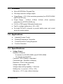
• Chapter 1, "Introduction", gives an overview of the product features,
applications, and specifications.
• Chapter 2, "Installation", describes how to install the 6208 series
products. The layout of 6208 series products are shown, the
connectors specifications, and the notes for installation are
described.
• Chapter 3, "Registers Format", describes the details of register
format and structure of the 6208 series products, this information is
very important for the programmers who want to control the
hardware by low-level programming.
• Chapter 4, "Operation Theorem", describes more detail concept
about 6208’s functions, including analog output and range control
systems.
• Chapter 5, "Software Library", describes the software libraries for
programming the 6208 series cards. The software libraries for DOS
and Windows 95/98 are provided. It helps users to control 6208
series cards in high-level programming languages.
• Chapter 6, "Utility/Calibration", describes how to run the utility
program included in the software CD. And how to calibrate the 6208
series cards for accurate operation.
How to Use This Guide • iii
1
Introduction
The 6208 series products are multi-channel analog output cards. They
include the following three products:
•
•
•
cPCI/PCI-6208V: 8-CH voltage output card for cPCI/PCI interface
cPCI/PCI-6208A: 8-CH voltage and current output card for
cPCI/PCI interface
PCI-6216V: 16-CH voltage output card for PCI interface
cPCI/PCI-6208V:
cPCI/PCI-6208V is a high-density analog output card with 8 identical
voltage output channels. Each channel is equipped with B.B.PCM56U
which is a state-of-the-art fully monotonic, digital to analog converter.
This device employs ultra-stable nichrome (NiCr) thin-film resistors to
provide monotonicity, low distortion, and low differential linearity error
over long period of time.
PCI-6216V:
cPCI/PCI-6216V is a high-density analog voltage output card, it is a
combination of cPCI/PCI-6208 with EXP-8V daughter board. The EXP8V is an extended board which includes extra 8 voltage output
channels.
cPCI/PCI-6208A:
cPCI/PCI-6208A is a high-density current source output card, it is a
combination of cPCI/PCI-6208V with EXP-8A daughter board. The EXP8A includes 8 precision voltage-to-current converters which convert
voltage outputs from cPCI/PCI-6028V to current source outputs.
Introduction • 1
1.1 Features
l
32-bit cPCI/PCI-Bus, Plug and Play
l
16-bit high resolution voltage outputs
l
Output Range : ±10V (14-bit resolution guarantee) for cPCI/PCI-6208V
and PCI-6216V only
l
Output Range : 0-20mA, 4-20mA, 5-25mA (14-bit resolution
guarantee) for cPCI/PCI-6208A only
l
0.001% of FSR typical. Differential linearity error
l
Fast 2 µs voltage settling time (-10V~+10V)
l
On board DC-to-DC converter to provide stable power and current
source for analog outputs
1.2 Applications
l
Industrial Process Control
l
Pressure/Temperature Transmitter
l
Current Source for Testing Equipment
l
Function Generator
1.3 Specifications
♦
Voltage Output
Numbers of channel:
8 channels for cPCI/PCI-6208V and cPCI/PCI-6208A
16 channels for PCI-6216V
Converter : B.B. PCM56U or equivalent
Conversion type : Monolithic multiplying
Resolution: 16-bit (14-bit guarantee)
Voltage output ranges: ±10V
Voltage output driving capability: ± 5mA max.
Settling time : 2µ second (-10V to +10V)
Gain error: ± 0.2 % (max, without trimming)
2 • Introduction
Differential Linearity Error: ± 0.001 % Full Scale Range
Output initial status : 0V (after RESET or POWER-ON)
Data Transfer: Programmed I/O
♦
Current Output
Numbers of channel:
8 channel for cPCI/PCI-6208A
Current output ranges: (software programmable)
q 0~20mA, 4~20mA, 5~25mA.
Voltage to current converter: B.B. XTR110 or equivalent
Settling time: 17 µ second (0~20mA)
Slew rate: 1.3mA / µs
Non-linearity: ± 0.01 % of Span
Span error: 0.3% of initial Span
Output resistance: 10 Ohms maximum
Output initial status : 0mA (after RESET or POWER-ON)
♦
Digital I/O
• Channel : 4 TTL compatible inputs and outputs
•
Input Voltage :
•
Low : Min. 0V; Max. 0.8V
High : Min. +2.0V; Max. 5.5V
Input Load :
Low : +0.8V @ -0.2mA max.
High : +2.7V @ +20mA max.
Output Voltage :
•
Low : Min. 0V; Max. 0.4V
High : Min. +2.4V; Max. 5.5V
Driving Capacity :
Low : Max. +0.5V at 8.0mA (Sink)
High : Min. 2.7V at 0.4mA (Source)
♦
General Specifications
Operating temperature: 0° ~ 55°C
Storage temperature: -20° ~ 80°C
Humidity: 5 ~95% non-condensing
Introduction • 3
Connector: 37-pin D-sub connector (female)
Bus interface: 32-bit slave PCI bus
Power consumption:
qPCI-6208V: +5VDC @ 580mA typical
+12VDC @ 70mA typical
qPCI-6208A: +5VDC @ 670mA typical
+12VDC @ 90mA typical
or +12VDC @ 370mA
(when all current output channel is 25mA)
qPCI-6216V: +5VDC @ 1.24 typical
+12VDC @ 110mA typical
qcPCI-6208V: +5VDC @ 560mA typical
+12VDC @ 70mA typical
qcPCI-6208A: +5VDC @ 650mA typical
+12VDC @ 90mA typical
or +12VDC @ 370mA
(when all current output channel is 25mA)
PCB Dimension: Half-sized
qPCI series: 153 mm x 98 mm
qcPCI series: 160 mm x 100 mm
4 • Introduction
2
Installation
This chapter describes how to install the 6208 series card. Please follow
the following steps to complete the installation.
2.1 What You Have
In addition to this User's Manual, the package includes the following
items:
l
6208 Series Card
l
Manual & Software Utility CD
If any of these items is missing or damaged, contact the dealer whom
you purchased the product from. Save the shipping materials and carton
in case you want to ship or store the product in the future.
2.2 Unpacking
Your 6208 series card contains sensitive electronic components that can
be easily damaged by static electricity.
The card should be done on a grounded anti-static mat. The operator
should be wearing an anti-static wristband, grounded at the same point
as the anti-static mat.
Inspect the card module carton for obvious damage. Shipping and
handling may cause damage to your module. Be sure there are no
shipping and handing damages on the module before processing.
Installation • 5
After opening the card module carton, exact the system module and
place it only on a grounded anti-static surface component side up.
Note : DO NOT APPLY POWER TO THE CARD IF IT HAS BEEN
DAMAGED.
You are now ready to install your 6208 series card.
2.3 Device Installation for Windows 95/98
While you first plug 6208 series card and enter Windows 95/98, the
system will detect this device automatically. Please follow the steps to
install the device.
1.
Click the Next button in the Update Device Driver Wizard window,
Win95 will start to search floppy drive A for the 6208 series driver
information, After fail to find the information in drive A, it will
display the message “Windows was unable to locate a driver for
this device.”
2.
Insert ADLink’s All-in-one CD-ROM drive.
3.
Click the “Other Location…” button in the Update Device Driver
Wizard Window, then the Select Other Location windows will
appear.
4.
Click Browse button to invoke the Browser for Folder window, then
select the location
X:\Win95Inf\6208 (X indicates the CD-ROM drive).
6 • Installation
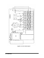
2.4 PCB Layout
Figure 2.1a PCI-6208 Layout
Installation • 7
Figure 2.1b cPCI-6208 Layout
8 • Installation
2.5 Connector Pin Assignment
The pin assignment of 6208 series card are shown in Figure 2.2
DI3
(1)
DI2
(2)
DI1
(3)
DI0
(4)
GND
(5)
+5V
(6)
+15V
(7)
A.GND
(8)
V14(A6)
(9)
V6 (10)
A.GND (11)
V12(A4) (12)
V4 (13)
A.GND (14)
V10(A2) (15)
V2 (16)
A.GND (17)
V8(A0) (18)
V0 (19)
(20) DO3
(21) DO2
(22) DO1
(23) DO0
(24) GND
(25) -15V
(26) A.GND
(27) V15(A7)
(28) V7
(29) A.GND
(30) V13(A5)
(31) V5
(32) A.GND
(33) V11(A3)
(34) V3
(35) A.GND
(36) V9(A1)
(37) V1
Figure 2.2 Pin Assignment of CN1 connector
The analog output pin names are specified as Vn or An, where
Vn : means the voltage output with channel number n
for cPCI/PCI-6208V, n=0~7
for PCI-6216V, n=0~15
An : means the current output with channel number n
for cPCI/PCI-6208A only, n=0~7
The digital input and output pin names are specified as DIn and DOn
respectively, where n=0~3.
Installation • 9
2.6 Install 6208 Series Card to cPCI/PCI Connector
Note that the PC power should be ‘OFF’ before installing, and be careful
to install the cards properly and tighten the screw. Improper installation
of the cPCI/PCI cards may damage the cards.
2.6.1
Hardware configuration
Memory usage (I/O port locations) of the cPCI/PCI card is assigned by
system BIOS. The address assignment is done on a board-by-board
basis for all cPCI/PCI cards in the system.
2.5.2
PCI slot selection
Your computer probably have both PCI and ISA slots. Do not force the
PCI card into a PC/AT slot. PCI slots are shorter than ISA or EISA slots
and are usually white or ivory.
2.5.3
Installation Procedures
1.
Turn off your computer.
2.
Turn off all accessories (printer, modem, monitor, etc.) connected to
computer.
3.
Remove the cover from your computer.
4.
Select a 32-bit cPCI/PCI expansion slot.
5.
Before handling the 6208 series card, discharge any static buildup
on your body by touching the metal case of the computer. Hold the
edge and do not touch the components.
6.
Position the board into the cPCI/PCI slot you selected.
7.
Secure the card in place at the rear panel of the system unit by
using screw removed from the slot.
2.5.4
Running the 6208UTIL.EXE
A testing program is included in this utility, you can check if your 6208
series card can work properly. Refer Chapter 6 for further detailed
information.
10 • Installation
3
Registers Format
In this chapter, the register format of the analog output channel and
digital I/O ports are introduced. Before programming or applying the
6208 series cards to your applications, please go through this chapter to
understand the features of the functions.
The 6208 functions as a 32-bit PCI target device to any master on the
PCI bus. There are three types of registers: PCI Configuration Registers
(PCR), Local Configuration Registers (LCR) and 6208 registers.
The PCR, which compliant to the PCI-bus specifications, is
initialized and controlled by the plug & play (PnP) PCI BIOS.
User‘s can study the PCI BIOS specification to understand the
operation of the PCR. Please contact with PCISIG to acquire the
specifications of the PCI interface.
The LCR is specified by the PCI bus controller PLX-9050, which is
provided by PLX technology Inc. (www.plxtech.com) . It is not necessary
for users to understand the details of the LCR if you use the software
library. The base address of the LCR is assigned by the PCI PnP BIOS.
The assigned address is located at offset 14h of PCR.
Register format • 11
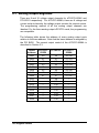
3.1 Analog Output Registers
There are 8 and 16 voltage output channels for cPCI/PCI-6208V and
PCI-6216V respectively. For cPCI/PCI-6208A, there are 8 voltage and
current out-put channels, the voltage output controls the current source.
The programming method of all the analog output channels are
identical. For the three analog output cPCI/PCI cards, the programming
are compatible.
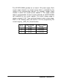
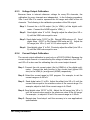
The following table shows the address of every analog output ports
relative to the base address. Note that the base address is assigned by
the PCI BIOS. The current output control of the cPCI/PCI-6208A is
described in Section 3.3.
Offset
Address
0x00
0x02
0x04
0x06
0x08
0x0A
0x0C
0x0E
0x10
0x12
0x14
0x16
0x18
0x1A
0x1C
0x1E
12 • Register format
CPCI/PCI6208V
V0
V1
V2
V3
V4
V5
V6
V7
---------
PCI-6216V
V0
V1
V2
V3
V4
V5
V6
V7
V8
V9
V10
V11
V12
V13
V14
V15
cPCI/PCI6208A
V0 / A0
V1 / A1
V2 / A2
V3 / A3
V4 / A4
V5 / A5
V6 / A6
V7 / A7
---------
3.2 Analog Output Status Register
The DAC is with series bus hence it take times to send digital value out.
The data transfer time for every DA data write takes 2.2µs, therefore the
software driver must wait for 2.2µs before send another data to any
analog output port. While the DA value is sending, the Data_Send bit is
‘H’. The software driver should check this bit before write any data to
output port. This register is read only.
Offset Address
0x00
D16~D1
X
D0
Data_Send
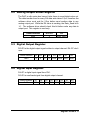
3.3 Digital Output Register
D0~D3 is the digital output signal written to output channel. D4~D7 don’t
care.
Offset Address
0x40
D7
X
D6
X
D5 D4
X
X
D3
D2
DO3 DO2
D1
D0
DO1 DO0
3.5 Digital Input Register
D4~D7 is digital input signal from CN1.
D0~D3 is read back signal from digital output channel.
Offset Address
0x40
D7
DI3
D6
DI2
D5
DI1
D4 D3 D2 D1 D0
DI0 DO3 DO2 DO1 DO0
Register format • 13
4
Operation Theorem
In this chapter, the detail operation theorem of 6208 series cards is
described. Before programming or applying the 6208 series cards to
your applications, please go through this chapter to understand the
features of the functions.
4.1 Voltage Output
The DA converters used on the cPCI/PCI-6208 are Burr-Brown PCM56U. The DAC is 16 bit resolution with bi-polar output. The voltage
output range is +/-10V. Therefore, the data register are all 16-bits value
with sign. The digital value range from -32768 (0X8000) to +32767
(0x7FFF) is corresponding to -10 Volt to +10 Volt. Table 3.1 shows the
relation between the digital value and the analog output voltage.
When the applications use smaller voltage range, the cPCI/PCI-6208
can still be applied. For example, if the application voltage range is unipolar 0~5V, the user just use digital value range of 0~16384 with 14 bit
voltage resolution.
Operation Theorem • 15
Digital Value
32767
16384
8192
1
0
-1
-8192
-16384
-32767
-32768
HEX value
0x7FFF
0x4000
0x2000
0x0001
0x0000
0xFFFF
0xE000
0xC000
0x8001
0x8000
Output Voltage
+9.99969V
+5.00000V
+2.50000V
0.00031V
0.00000V
-0.00031V
-2.50000V
-5.00000V
-9.99969V
-10.00000V
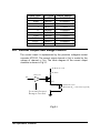
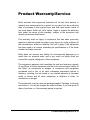
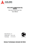
4.2 Current Output and Range Control
The current output is implemented by the precision voltage-to-current
converter XTR110. The current output channel n (An) is control by the
voltage of channel n (Vn). The block diagram of the current output
channels is shown in Fig 3.1.
On Board +15V
XTR110
50 Ohm
Vn
An
Io
C u rrent O u tput
R a n g e C o n trol
A.GND
Fig 3.1
16 • Operation Theorem
External Load
(R e s i s t e r R L = 2 5 0 O h m t y p i c a l )
The cPCI/PCI-6208A provides an on board +15V power supply. Each
current output channel is a current source which is controlled by the
voltage of the corresponding channel. For example, voltage output
channel 3 control the current source channel 3. The output current
range is programmable. All the 8 current channels on cPCI/PCI-6208A
are controlled by one control register. The control voltage range is
always uni-polar 0~10V. There are three kinds of output current range.
Refer to the following table and Section 5.2.8 for programming the
current range by _6208_I2V_Control function.
Mode
1
2
3
Input Voltage
Range
0~10V
0~10V
0~10V
Output Current
Range
0~20 mA
4~20 mA
5~25 mA
Operation Theorem • 17
5
Software Library
This chapter describes the software library for programming the 6208 series
cards. The software library for DOS and Windows 95 are provided. Seven Clanguage functions are provided in this software library to support users to
program their own applications. The function prototypes and some useful
constants are defined in the Pci_6208.h and Acl_pci.h.
5.1 Installation
5.1.1
MS-DOS Software Installation
step 1. Place ADLink’s “All-in-one” CD into the appropriate CD drive.
step 2. Type the command (X indicates the CD ROM driver):
X:\> CD\NuDAQPCI\6208\DOS
X:\NuDAQPCI\6208\DOS> SETUP
step 3. An installation completed message will be shown on the screen.
After installation, all the files of cPCI/PCI-6208/6216 Library & Utility for
DOS are stored in C:\ADLink\6208\DOS directory.
5.1.2
Windows 95/98 Software Installation
step 1. Place ADLink’s “All-in-one” CD into the appropriate CD drive.
step 2. If autorun setup program is not invoked automatically, please
execute X:\setup.exe (X indicates the CD-ROM drive).
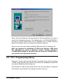
step 3. Select NuDAQ PCI Drivers Win 95/98 PCI-6208
Software Library • 19
After a welcome dialog box, Setup prompts the following dialog box for you to
specify the destination directory. The default path is C:\ADLink\6208\W95. If
you want to install 6208 series DLL for Windows 95 in another directory,
please click Browse button to change the destination directory.
Then you can click next to begin installing 6208 series DLL for Windows 95.
After you complete the installation of 6208 series Software, 6208 series
DLL (6208.DLL) is copied to Windows System directory (default is
C:\WINDOWS\SYSTEM for Win-95/98) and the driver file PCIW95.VXD) is
also copied to the appropriate directory.
5.2 C/C++ Programming Library
There are 7 function calls provided by the C Language Library. All the functions
of 6208 series products are covered in this library. Its capabilities include D/A
conversion, Digital Input and Output, etc.
The functions of 6208 series software driver are using full-names to represent
the functions' real meaning. The naming convention rules are:
20 • Software Library
In DOS Environment :
_{hardware_model}_{action_name}. e.g. _6208_Initial().
All functions in cPCI/PCI-6208V/A, PCI-6216 library are with 6208 as
{hardware_model}. But they can be used by cPCI/PCI-6208V, cPCI/PCI6208A, and PCI-6216V.
In order to recognize the difference between DOS library and Windows 95
library, a capital "W" is put on the head of each function name of the Windows
95 DLL driver e.g.
W_6208_Initial().
5.2.1
Data Types
We defined some data type in Pci_6208.h (DOS) and Acl_pci.h (Windows 95).
These data types are used by 6208 series library. We suggest you to use
these data types in your application programs. The following table shows the
data type names and their range.
Type Name
U8
I16
U16
I32
U32
F32
F64
Boolean
5.2.2
Description
8-bit ASCII character
16-bit signed integer
16-bit unsigned integer
32-bit signed integer
32-bit single-precision
floating-point
32-bit single-precision
floating-point
Range
0 to 255
-32768 to 32767
0 to 65535
-2147483648 to 2147483647
0 to 4294967295
64-bit double-precision
floating-point
Boolean logic value
-1.797683134862315E308 to
1.797683134862315E309
TRUE, FALSE
-3.402823E38 to
3.402823E38
_6208_Initial
@ Description
This function is used to initialize 6208 series cards. You have to call this
function to initialize all 6208 series cards plugged on your system, then you
can call other function to perform operations on the cards.
Software Library • 21
@ Syntax
C/C++ (DOS)
U16 _6208_Initial (U16 *existCards, PCI_INFO *pciInfo)
C/C++ (Windows 95/98)
U16 W_6208_Initial (U16 *existCards, PCI_INFO *pciInfo)
Visual Basic (Windows 95/98)
W_6208_Initial (existCards As Integer, pciInfo As PCI_INFO) As Integer
@ Argument
existCards:
pciinfo:
number of existing 6208 series cards
relative information of the 6208 series cards
@ Return Code
ERR_NoError
ERR_BoardNoInit
ERR_PCIBiosNotExist
5.2.3
_6208_Software_Reset
@ Description
This function is used to reset the I/O port configuration. Note that this
function can not re-start the PCI bus and all the hardware settings won’t be
changed either.
@ Syntax
C/C++ (DOS)
void _6208_Software_Reset (U16 cardNo)
C/C++ (Windows 95/98)
void W_6208_Software_Reset (U16 cardNo)
Visual Basic (Windows 95/98)
W_6208_Software_Reset (ByVal cardNo As Integer)
@ Argument
cardNo: The card number of 6208 series card initialized. The first card (in
the most prior PCI slot) is with cardNo = 0.
@ Return Code
ERR_NoError
22 • Software Library
5.2.4
_6208_DA
@ Description
This function is used to write data to D/A converters. There are 8 and 16
Digital-to-Analog conversion channels on the cPCI/PCI-6208.and PCI-6216
respectively. The resolution of each channel is 16 bits with sign; i.e. the
digital value range from -32768 (0x8000) to +32767 (0x7FFF). The
following table shows the output data format and the relation between the
digital value and the analog output voltage:
Digital value
32767
16384
8192
1
0
-1
-8192
-16384
-32767
-32768
HEX value
0x7FFF
0x4000
0x2000
0x0001
0x0000
0xFFFF
0xE000
0xC000
0x8001
0x8000
Output Voltage
+9.99969V
+5.00000V
+2.50000V
0.00031V
0.00000V
-0.00031V
-2.50000V
-5.00000V
-9.99969V
-10.00000V
@ Syntax
C/C++ (DOS)
U16 _6208_DA (U16 cardNo, U16 chn, I16 DAData)
C/C++ (Windows 95/98)
U16 W_6208_DA (U16 cardNo, U16 chn, I16 DAData)
Visual Basic (Windows 95/98)
W_6208_DA (ByVal cardNo As Integer, ByVal chn As Integer, ByVal
DAData As Integer) As Integer
@ Argument
cardNo: The card number of 6208 series card initialized. The first card (in
the most prior PCI slot) is with cardNo = 0.
Chn:
D/A channel number
DAData: D/A converted value
Software Library • 23
@ Return Code
ERR_NoError
5.2.5
_6208_Get_DA_Status
@ Description
This function is used to check the DA data sending status. Because the
data transfer time for every DA data takes 2.2 µs, the software driver must
wait for 2.2µs before sending another data to any analog output port. This
function should be called before writing any data to output port. While the
DA value is sending, the returned value is “1”, otherwise the returned value
is “0”.
@ Syntax
C/C++ (DOS)
U16 _6208_Get_DA_Status (U16 cardNo)
C/C++ (Windows 95/98)
U16 W_6208_Get_DA_Status (U16 cardNo)
Visual Basic (Windows 95/98)
W_6208_Get_DA_Status (ByVal cardNo As Integer) As Integer
@ Argument
cardNo: The card number of 6208 series card initialized. The first card (in
the most prior PCI slot) is with cardNo = 0.
@ Return Code
0 (low): no DA value is sending
1 (high): the DA value is sending
5.2.6
_6208_DI
@ Description
This function is used to read data from digital input ports. There are 4 digital
input channels on 6208 series card. The retrieved value is stored in DIData.
However the returned value need to be handled further by including the
following code in you program :
*DIData = (*DIData&0xF0)>>4
24 • Software Library
@ Syntax
C/C++ (DOS)
U16 _6208_DI (U16 cardNo, U16 *DIData)
C/C++ (Windows 95/98)
U16 W_6208_DI (U16 cardNo, U16 *DIData)
Visual Basic (Windows 95/98)
W_6208_DI (ByVal cardNo As Integer, DIData As Integer) As Integer
@ Argument
cardNo: the card number of 6208 series card initialized. The first card (in
the most prior PCI slot) is with cardNo = 0.
DIData: the value read from digital input port, please refer to the above
description paragraph for getting the correct DI data
@ Return Code
ERR_NoError
5.2.7
_6208_DO
@ Description
This function is used to write data to digital output ports. There are 4 digital
output channels on 6208 series card, i.e. the output value ranges from 0 to
15.
@ Syntax
C/C++ (DOS)
U16 _6208_DO (U16 cardNo, U16 DOData)
C/C++ (Windows 95/98)
U16 W_6208_DO (U16 cardNo, U16 DOData)
Visual Basic (Windows 95/98)
W_6208_DO (ByVal cardNo As Integer, ByVal DOData As Integer) As
Integer
Software Library • 25
@ Argument
cardNo: the card number of 6208 series card initialized. The first card (in
the most prior PCI slot) is with cardNo = 0.
DOData: the value written to digital output port
@ Return Code
ERR_NoError
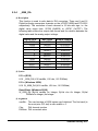
5.2.8
_6208_I2V_Control
@ Description
This function is used to set cPCI/PCI-6208A voltage-to-current mode
control. There are three modes of range for cPCI/PCI-6208A. Please refer
to section 3.3 for the detailed description of voltage to current conversion.
The three voltage-to-current modes are:
Mode
I_0to20mA
I_4to20mA
I_5to25mA
Input Voltage
Range
0~10V
0~10V
0~10V
Output Current
Range
0~20 mA
4~20 mA
5~25 mA
@ Syntax
C/C++ (DOS)
U16 _6208_I2V_Control (U16 cardNo, U16 ctrl)
C/C++ (Windows 95/98)
U16 W_6208_DO (U16 cardNo, U16 DOData)
Visual Basic (Windows 95/98)
W_6208_I2V_Control (ByVal cardNo As Integer, ByVal ctrl As Integer) As
Integer
26 • Software Library
@ Argument
cardNo: the card number of 6208 series card initialized. The first card (in
the most prior PCI slot) is with cardNo = 0.
ctrl:
the voltage-to-current mode, the valid modes are shown in the
above table. The constants are defined in Pci_6208.h (DOS) and
Acl_pci.h (Windows 95).
@ Return Code
ERR_NoError
Software Library • 27
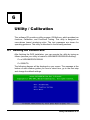
6
Utility / Calibration
This software CD provides a utility program, 6208util.exe, which provides two
functions, Calibration, and Functional Testing. This utility is designed as
menu-driven based windowing style. The text messages are shown for
operating guidance. This utility is described in the following sections.
6.1 Running the 6208util.exe
After finishing the DOS installation, you can execute the utility by typing as
follows (assume your utility is located in \ADLINK\DOS\6208\Util directory)
C> cd \ADLINK\DOS\6208\Util
C> 6208UTIL
The following diagram will be displayed on you screen. The message at the
bottom of each window guides you how to select item, go to the next step
and change the default settings.
Utility/Calibration • 29
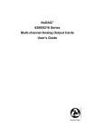
6.1.1
Functional Testing
This function is used to test the D/A functions of cPCI/PCI-6208V /6208A
/6216V.
When you choose one of the testing function from the functions menu, a
channel selection menu is displayed on the screen. Move cursor and press
<Enter> to select the channel you want to test. After you select a channel
from the channel selection menu, a testing window appears. The figures
below are the function testing menu window, 6208V Testing window.
Fig. 6.1 Function Testing Menu Window
Fig. 6.2 6208V Testing Window
30 • Utility/Calibration
6.1.2
Calibration
This function guides you to calibrate the 6208 series card. The calibration
program serves as a useful test of the 6208 series D/A functions and can aid
in troubleshooting if problems arise.
Note : For an environment with frequently large changes of temperature and
vibration, a 3 months re-calibration interval is recommended. For
laboratory conditions, 6 months to 1 year is acceptable
When you choose the calibration function from the main menu list, a
calibration items menu is displayed on the screen. After you select one of the
calibration items from the calibration items menu, a calibration window
shows. The instructions will guide you to calibrate each item step by step.
If you select 1, the following figure displays on the screen:
Utility/Calibration • 31
Use <Up/Down> to select a DA Channel or ‘q’ to exit
After you select a channel from the channel selection menu, a calibration
window appears. The figures below are the 6208V calibration window.
32 • Utility/Calibration
6.2 Calibration of Analog Output Channel
6.2.1
What You Need
Before calibrating your 6208 series card, you should prepare a 6 1/2 digital
multimeter for measruing the voltage signals.
6.2.2
VR Assignemnt of cPCI/PCI-6208 and PCI-6216
There are 8 and 16 voltage output channels on cPCI/PCI-6208 and PCI6216, respectively. For each channel, two VRs are used for adjustment the
full range and offset of the output voltage. The follow table shows the
assignment and function of the VRs.
VR of
PCI6208V or
PCI6216V
VR0-1
VR0-2
VR1-1
VR1-2
VR2-1
VR2-2
VR3-1
VR3-2
VR4-1
VR4-2
VR5-1
VR5-2
VR6-1
VR6-2
VR7-1
VR7-2
Function
Ch #0 full range
Ch #0 offset
Ch #1 full range
Ch #1 offset
Ch #2 full range
Ch #2 offset
Ch #3 full range
Ch #3 offset
Ch #4 full range
Ch #4 offset
Ch #5 full range
Ch #5 offset
Ch #6 full range
Ch #6 offset
Ch #7 full range
Ch #7 offset
VR of
PCI6216V
VR8-1
VR8-2
VR9-1
VR9-2
VR10-1
VR10-2
VR11-1
VR11-2
VR12-1
VR12-2
VR13-1
VR13-2
VR14-1
VR14-2
VR15-1
VR15-2
Function
Ch #8 full range
Ch #8 offset
Ch #9 full range
Ch #9 offset
Ch #10 full range
Ch #10 offset
Ch #11 full range
Ch #11 offset
Ch #12 full range
Ch #12 offset
Ch #13 full range
Ch #13 offset
Ch #14 full range
Ch #14 offset
Ch #15 full range
Ch #15 offset
Utility/Calibration • 33
6.2.3
Voltage Output Calibration
Because there is internal reference voltage for every DA channels, the
calibration for every channels are independent. In the following procedure,
VRn-1 and VRn-2 is used to represent the full range and offset of the nth
channels. The following is the calibration procedure of the DA output.
Step 1. Connect the n th DA output (Vn) to VDM(+) of the digital multimeter. Connect the AGND signal to VDM (-).
Step 2. Send digital value ‘0’ to DA. Roughly adjust the offset (trim VR n2) until the VDM value equal to zero.
Step 3. Send digital value ‘32767’ to DA. Record VDM value as V1. Send
digital value ‘-32767’ to DA. Record VDM value as V2. Adjust the
full range (trim VR n-1) until V1-V2 value equal to +20V.
Step 4. Send digital value ‘0’ to DA. Precisely adjust the offset (trim VR n2) until the VDM value equal to zero.
6.2.4
Current Output Calibration
The current output calibration is used only on cPCI/PCI-6208A. Because the
current output channel n is controlled by the voltage of channel n, the VR n-1
and VR n-2 is also used for calibrating the n-th current output channel.
Step 1. Connect the n-th current output (An) to VDM(A+) of the digital multimeter. Connect the both junction of the current load (typical 250
ohm) to the VDM (A-) and ground (AGND) respectively.
Step 2. Select the current range by S/W program. For example, to set the
current range as 4~20 mA.
Step 3. Send digital value ‘0’ to DA. Adjust the offset (trim VR n-2) until the
current value equal to the minimum value of the current range. For
example, adjust to 4mA if the current range is 4~20mA.
Step 4. Send digital value ‘32767’ to DA. Adjust the full range (trim VR n-1)
until the current value equal to the maximum value of the full range.
For example , to adjust to 20 mA if the current range is 4~20mA.
Step 5. Repeat step 3 and step 4 until the accuracy is in user application‘s
specifications.
34 • Utility/Calibration
Product Warranty/Service
Seller warrants that equipment furnished will be free form defects in
material and workmanship for a period of one year from the confirmed
date of purchase of the original buyer and that upon written notice of
any such defect, Seller will, at its option, repair or replace the defective
item under the terms of this warranty, subject to the provisions and
specific exclusions listed herein.
This warranty shall not apply to equipment that has been previously
repaired or altered outside our plant in any way as to, in the judgment of
the manufacturer, affect its reliability. Nor will it apply if the equipment
has been used in a manner exceeding its specifications or if the serial
number has been removed.
Seller does not assume any liability for consequential damages as a
result from our products uses, and in any event our liability shall not
exceed the original selling price of the equipment.
The equipment warranty shall constitute the sole and exclusive remedy
of any Buyer of Seller equipment and the sole and exclusive liability of
the Seller, its successors or assigns, in connection with equipment
purchased and in lieu of all other warranties expressed implied or
statutory, including, but not limited to, any implied warranty of merchant
ability or fitness and all other obligations or liabilities of seller, its
successors or assigns.
The equipment must be returned postage-prepaid. Package it securely
and insure it. You will be charged for parts and labor if you lack proof of
date of purchase, or if the warranty period is expired.
Product Warranty/Service • 35