1
Allen-Bradley
User Manual for 3000/5000 VA UPS
1609-P3000N
1609-P3000H
1609-P3000A
1609-P5000E
3000 VA 120 VAC
3000 VA 208 VAC
3000 VA 230 VAC
5000 VA 208/230 VAC
Tower/Rack-Mount 3U
Uninterruptible Power Supply
41063-260-01(1)
990-2671 09/2005
INSTALLATION
Read the Safety Instruction sheet before installing the UPS.
Unpacking
Inspect the UPS upon receipt. Notify the carrier and dealer if there is damage.
The packaging is recyclable; save it for reuse or dispose of it properly.
Check the package contents:
q
q
q
UPS
Front bezel
Literature kit containing:
®
q PowerChute Business Edition CD
q
q
q
q
q
Bulletin 1609-P Series User Manual CD
1609-P5000E models only:
1609-NMC (Network Management Card installed in slot located in rear of unit)
1609-P5000E models only: Network Management Card CD
Serial cable
Quick Start Guide
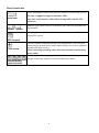
Environmental Specifications
TEMPERATURE
O PERATING
STORAGE
32° to 104° F (0° to 40° C)
5° to 113° F (-15 to 45 ° C) charge UPS battery every six months
M AXIMUM
ELEVATION
O PERATING
STORAGE
10,000 ft (3,000 m)
50,000 ft (15,000 m)
HUMIDITY
0% to 95% relative humidity, non-condensing
1
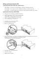
This unit is intended for
indoor use only. Select a
location sturdy enough to
handle the weight.
Do not operate the UPS where
there is excessive dust or the
temperature and humidity are
outside the specified limits.
Ensure the air vents on the
front and rear of the UPS
are not blocked.
Wiring and Connecting the UPS
CONNECTING UPS USING POWER CORD : 3000 VA UNITS
1609-P3000N – Use captive 8 ft cord. NEMA L5-30 Plug is attached to this cord.
1609-P3000H – Use in captive 8 ft cord. NEMA L6-30 Plug is attached to this cord.
1609-P3000A – User must supply power cord. Power cord must mate with IEC 320 C20 inlet.
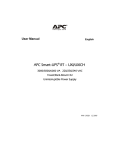
HARDWIRING INSTRUCTIONS: 1609-P5000E
•
Wiring must be performed by a qualified electrician.
•
Install a high magnetic 30/32 A utility circuit breaker,
(Allen-Bradley Catalog Number 1489-A2C300).
•
Adhere to all national and local electrical codes.
•
Use #10 AWG gauge (5 sq. mm) wire.
1.
2.
Switch the utility circuit breaker OFF.
Remove the input access panel.
3.
Remove circular knockout.
4.
Run #10 AWG gauge (5 sq. mm) wire through the access panel, and connect the wires to the
terminal block (Green: Ground, Brown: Hot, Blue: Neutral).
Use an appropriate strain relief (not included).
5.
6.
Switch the utility circuit breaker ON.
Check line voltages.
7.
Replace the access panel.
2
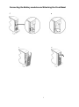
Connecting the Battery modules and Attaching the Front Bezel
∂
•
÷
≠
3
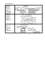
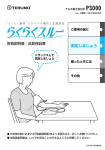
BASIC CONNECTORS
Power management software and interface cable can be used with the UPS.
Use only a supplied or approved interface cable.
serial com
Any other serial interface cable will be incompatible with the UPS
connector.
Manual bypass enables the user to manually put connected equipment into
bypass mode.
normal bypass
Emergency Power Off terminal allows the user to connect the UPS to the
central EPO system.
EPO terminal
TVSS screw
The UPS features a transient voltage surge-suppression (TVSS) screw for
connecting the ground lead on surge suppression devices such as telephone
and network line protectors.
When connecting grounding cable, disconnect the unit from the utility
power outlet.
Optional external battery packs provide extended runtime during power
outages. These units support up to ten external battery packs.
external battery
pack connector
4
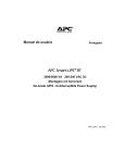
CIRCUIT BREAKERS
output circuit
breakers
1609-P5000E
1609-P3000A
output circuit
breakers
1609-P3000N
output circuit
breaker
1609-P3000H
5
Connecting Equipment and Power to the UPS
1.
2.
Connect equipment to the UPS.
Avoid using extension cords.
Turn on all connected equipment. To use the UPS as a master ON/OFF switch, ensure all
connected equipment is switched ON. The equipment will not be powered until the UPS is
turned on.
3.
To power up the UPS press the
•
5.
button on the front panel.
The UPS battery charges when it is connected to utility power. The battery charges to 90%
capacity during the first three hours of normal operation. Do not expect full battery run
capability during this initial charge period.
®
For additional computer system security, install PowerChute Business Edition Smart-UPS
monitoring software.
OPTIONS
q
External Battery Pack (1609-PXBP)
q
Rail Installation Kit (1609-PRK1)
Isolation Transformer (1609-5000CCT)
q
6
OPERATION
FRONT DISPLAY
Load
Battery Charge
Indicator
Description
Online
The Online LED illuminates when the UPS is drawing utility power and performing
double conversion to supply power to connected equipment.
On Battery
The UPS is supplying battery power to the connected equipment.
Bypass
The Bypass LED illuminates indicating that the UPS is in bypass mode. Utility
power is sent directly to connected equipment during bypass mode operation.
Bypass mode operation is the result of an internal UPS fault, an overload condition
or a user initiated command either through an accessory or the manual bypass
switch. Battery operation is not available while the UPS is in bypass mode. Refer to
Troubleshooting in this manual.
Fault
The UPS detects an internal fault.
Refer to Troubleshooting in this manual.
Overload
An overload condition exists. See Troubleshooting.
Replace
Battery
The battery is disconnected or must be replaced. See Troubleshooting.
Feature
Function
Power On
Press this button to turn on the UPS. (See below for additional capabilities.)
Power Off
Press this button to turn off the UPS.
7
Feature
Cold Start
Function
When there is no utility power and the UPS is off, press and hold the
power up the UPS and connected equipment.
button to
The UPS will emit two beeps. During the second beep, release the button.
Self-Test
Automatic: The UPS performs a self-test automatically when turned on, and every
two weeks thereafter (by default). During the self-test, the UPS briefly operates the
connected equipment on battery.
Manual: Press and hold the
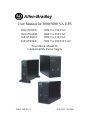
Diagnostic Utility Voltage
button for a few seconds to initiate the self-test.
The UPS has a diagnostic feature that displays the utility voltage. Plug
the UPS into the normal utility power.
The UPS starts a self-test as part of this procedure. The self-test
does not affect the voltage di s play.
Press and hold the
button to view the utility voltage bar graph
display. After a few seconds the five-LED, Battery Charge
display
on the right of the front panel shows the utility input voltage.
Refer to the figure at left for the voltage reading (values are not listed
on the UPS).
The display indicates the voltage is between the displayed value on the
list and the next higher value.
On Battery Operation
The UPS switches to battery operation automatically if the utility power fails. While running on
battery, an alarm beeps four times every 30 seconds.
Press the
button to silence this alarm. If the utility power does not return, the UPS continues to
supply power to the connected equipment until the battery is fully discharged.
When 2 minutes of run time remain the UPS emits a continuous beeping. If PowerChute is not being
used, files must be manually saved and the computer must be turned off before the UPS fully
discharges the battery.
8
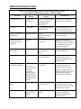
USER CONFIGURABLE ITEMS
NOTE : SETTINGS ARE MADE THROUGH SUPPLIED POWER CHUTE SOFTWARE,
OPTIONAL NETWORK MANAGEMENT CARDS, OR TERMINAL MODE.
FACTORY
USER SELEC TABLE
FUNCTION
DESCRIPTION
DEFAULT
CHOICES
Automatic Self-Test
Every 14 days
(336 hours)
Every 7 days(168 hours),
14 days (336 hours)
On Startup Only,
No Self-Test
Set the interval at which the
UPS will execute a self-test.
UPS ID
UPS_IDEN
Up t o eight characters to
define the UPS
Uniquely identify the UPS, (i.e.
server name or location) for
network management purposes.
Date of Last Battery
Replacement
Manufacture Date
Date of
Battery Replacement
mm/dd/yy
Reset this date when you replace
the battery modules.
Minimum Capacity
Before Return from
Shutdown
0 percent
0, 15, 25, 35, 50, 60, 75,
90 percent
Following a low-battery
shutdown, the battery modules
will be charged to the specified
percentage before powering
connected equipment.
Alarm Delay After
Line Failure
5 second delay
5 or 30 second delay
At Low Battery
Never
Mute ongoing alarms or disable
all alarms permanently.
Shutdown Delay
20 seconds
0, 20, 60, 120, 240, 480,
720, 960 seconds
Set the interval between the time
when the UPS receives a
shutdown command and the
actual shutdown.
Duration of
Low Battery Warning.
2 minutes
PowerChute
software provides
automatic,
unattended
shutdown when
approximately 2
minutes of battery
operated runtime
remains.
2, 5, 7, 10, 12, 15, 18,
20 minutes
The low battery warning beeps
are continuous when two
minutes of run time remain.
Change the warning interval
default to a higher setting if the
operating system requires a
longer interval for shutdown.
Synchronized Turn-on
Delay
0 seconds
0, 20, 60, 120, 240, 480,
720, 960 seconds
The UPS will wait the specified
time after the return of utility
power before turn-on (to avoid
branch circuit overload).
High Bypass Point
+10% of
output voltage
setting
+5%, +10%, +15%,
+20%
Maximum voltage that the UPS
will pass to connected
equipment during internal
bypass operation.
9
NOTE : SETTINGS ARE MADE THROUGH SUPPLIED POWER CHUTE SOFTWARE,
OPTIONAL NETWORK MANAGEMENT CARDS, OR TERMINAL MODE.
FACTORY
DEFAULT
FUNCTION
USER SELEC TABLE
CHOICES
DESCRIPTION
Low Bypass Point
-30% of output
voltage setting
-15%, -20%, -25%, -30%
Minimum voltage that the UPS
will pass to connected
equipment during internal
bypass operation.
Output Voltage
3 kVA 120 V
models:
120 VAC
208/230 V models:
230 VAC
3 kVA 120 V models:
120 VAC
Allows the user to select the on
battery output voltage.
Output Frequency
Automatic
50 ± 3 Hz or
60 ± 3 Hz
50 ± 3 Hz
50 ± 0.1 Hz
60 ± 3 Hz
60 ± 0.1 Hz
Sets the allowable UPS output
frequency. Whenever possible,
the output frequency tracks the
input frequency.
Number of
Battery Packs
1
Number of Connected
Internal Battery Packs,
(two modules per pack)
Defines the number of
connected battery packs for
proper run time prediction.
208/230 V models:
200, 208, 220, 230,
240 VAC
Connecting the EPO (Emergency Power Off) Option
The output power can be disabled in an emergency by closing a switch connected to the EPO.
Adhere to National and local electrical codes when wiring the EPO.
Rockwell Automation recommends Allen-Bradley Catalog Number 800F Emergency Stop Operator
as the interface to the EPO to connector.
The EPO switch is internally powered by the UPS for use with non-powered switch circuit breakers.
The EPO circuit is considered a Class 2 circuit, (UL, CSA standards) and a SELV circuit (IEC
standard).
Both Class 2 and SELV circuits must be isolated from all primary circuitry. Do not connect any
circuit to the EPO terminal block unless it can be confirmed that the circuit is Class 2 or SELV.
If circuit standard cannot be confirmed, use a contact closure switch.
10
Use one of the following cable types to connect the UPS to the EPO switch:
•
CL2: Class 2 cable for general use
•
CL2P: Plenum cable for use in ducts, plenums, and other spaces used for environmental air.
•
CL2R: Riser cable for use in a vertical run in a floor to floor shaft.
•
CLEX: Limited use cable for use in dwellings and for use in raceways.
•
For installation in Canada: Use only CSA certified, type ELC (extra-low voltage control cable).
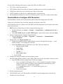
Terminal Mode to Configure UPS Parameters
Terminal Mode is a menu driven interface that enables enhanced configuration of the UPS.
Connect the serial cable to the serial com connector on the back of the UPS.
1609-P5000E models only: Remove the 1609-NMC network management card from the slot located
in the rear of the unit.
1.
2.
3.
4.
5.
6.
EXIT the PowerChute Business Edition using the following steps:
•
From the Desktop, go to Start => Settings => Control Panel => Administrative Tools =>
Services.
•
Select APC PCBE Server and APC PCBE Agent – right click the mouse and select Stop.
Open a terminal program. Example: HyperTerminal
•
From the Desktop, go to Start => Programs => Accessories => Communication
=>HyperTerminal.
Double-click on the HyperTerminal icon.
•
Follow the prompts to choose a name and select an icon. Disregard the message, “...must
install a modem,” if it is displayed. Click OK.
•
Select the COM port that is connected to your UPS. The port settings are:
ü bits per second - 2400
ü data - bits 8
ü parity - none
ü stop bit - 1
ü flow control - none
•
Press ENTER
Example for setting the number of external battery packs:
Once the blank terminal window is open, follow these steps to enter the number of battery packs:
•
Press ENTER to initiate terminal mode. Follow the prompts:
•
Press 1 to modify UPS Settings. Press e (or E) to modify the number of battery
packs. Enter the number of battery packs, including the internal battery pack
(Number of packs: 1= internal battery module,
2 = 1 external battery pack, 3 = 2 external battery packs, etc.).
Press ENTER.
•
Follow the prompts.
Exit the terminal program.
1609-P5000E models only: Re-install the 1609-NMC network management card in the slot
located in the rear of the unit.
11
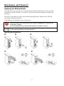
M AINTENANCE, AND TRANSPORT
Replacing the Battery Module
This UPS has an easy to replace, hot-swappable battery module. Replacement is a safe procedure,
isolated from electrical hazards. You may leave the UPS and connected equipment on during the
procedure.
The battery replacement procedure must include replacing all battery modules in the UPS and
connected external battery pack(s).
Typical Battery life expectancy is two to four years.
Once the battery(s) are disconnected, the connected equipment is not protected
from power outages.
Be careful during battery replacement-the battery modules are heavy.
Be sure to deliver spent batteries to a recycling facility or ship to the manufacturer
in the replacement battery packing material.
REMOVING BATTERY MODULES
u
x
v
w
y
12
REPLACING BATTERY MODULES
u
v
w
z
x
{
y
|
Disconnecting the Battery for Transport
Always DISCONNECT THE BATTERY(s) before shipping in compliance with U.S.
Department of Transportation (DOT) and IATA regulations.
The battery(s) may remain in the UPS.
1.
Shut down and disconnect any equipment attached to the UPS.
2.
Shut down and disconnect the UPS from the power supply.
3.
Unplug the battery connectors. Refer to Replacing Battery Modules in this manual.
13
TROUBLESHOOTING
PROBLEM AND POSSIBLE
CAUSE
UPS WILL NOT TURN ON
Battery not connected pro perly.
button not pushed.
SOLUTION
Check that the battery connectors are fully engaged.
Press the
button once to power the UPS and the connected equipment.
UPS not connected to utility
power supply.
Check that the power cable from the UPS to the utility power supply is securely
connected at both ends.
Very low or no utility voltage.
Check the utility power supply to the UPS by plugging in a table lamp. If the
light is very dim, have the utility voltage checked.
UPS WILL NOT TURN OFF
button not pushed.
Press the
Internal UPS fault.
button once to turn the UPS off.
Do not attempt to use the UPS. Unplug the UPS and have it serviced
immediately.
UPS BEEPS OCCASIONALLY
Normal UPS operation when
running on battery.
None. The UPS is protecting the connected equipment.
UPS DOES NOT PROVIDE EXPECTED BACKUP TIME
The UPS battery(s) are weak
due to a recent outage or
battery(s) are near the end of
their service life.
FRONT PANEL
LEDS FLASH SEQUENTIALLY
The UPS has been shut down
remotely through software or an
optional accessory card.
ALL
Charge the battery(s). Battery modules require recharging after extended outages.
They wear faster when put into service often or when operated at elevated
temperatures. If the battery(s) are near the end of their service life, consider
replacing the battery(s) even if the Replace Battery LED is not illuminated.
None. The UPS will restart automatically when utility power returns.
LEDS ARE OFF AND THE UPS IS PLUGGED INTO A WALL OUTLET
The UPS is shut down and the
battery is discharged from an
extended outage.
BYPASS AND OVERLOAD
The UPS is overloaded
None. The UPS will return to normal operation when the power is restored and
the battery has a sufficient charge.
LEDS ILLUMINATE, UPS EMITS A SUSTAINED ALARM TONE
The connected equipment exceeds the specified “maximum load” as defined in
Specifications section of the Quick Start Guide.
The alarm remains on until the overload is removed. Disconnect nonessential
equipment from the UPS to eliminate the overload condition.
14
PROBLEM AND POSSIBLE
CAUSE
BYPASS LED ILLUMINATES
The bypass switch has been
turned on manually or through
an accessory.
FAULT AND OVERLOAD
SOLUTION
If bypass is the chosen mode of operation, ignore the illuminated LED.
If bypass is not the chosen mode of operation move the bypass switch on the
back of the UPS, to the normal position.
LEDS ILLUMINATE, UPS EMITS A SUSTAINED ALARM TONE
The UPS has ceased sending
power to connected equipment.
The connected equipment exceeds the specified “maximum load” as defined in
Specifications section of the Quick Start Guide.
Disconnect nonessential equipment from the UPS to eliminate the overload
condition.
Press the OFF button, then the ON button to restore power to connected
equipment.
FAULT
LED ILLUMINATES
Internal UPS fault.
REPLACE BATTERY
Do not attempt to use the UPS. Turn the UPS off and have it serviced
immediately.
LED
ILLUMINATES
Replace Battery LED flashes and
short beep is emitted every two
seconds to indicate the battery is
disconnected.
Check that th e battery connectors are fully engaged.
Weak battery.
Allow the battery to recharge for 24 hours. Then, perform a self-test. If the
problem persists after recharging, replace the battery.
Failure of a battery self-test.
The UPS emits short beeps for one minute and the Replace Battery LED
illuminates. The UPS repeats the alarm every five hours. Perform the self-test
procedure after the battery has charged for 24 hours to confirm the Replace
Battery condition. The alarm stops and the LED clears if the ba ttery passes the
self-test.
UPS OPERATES ON BATTERY ALTHOUGH NORMAL LINE VOLTAGE EXISTS
Very high, low, or distorted line
voltage. Inexpensive fuel
powered generators can distort
the voltage.
Move the UPS to a different outlet on a different circuit. Test t he input voltage
with the utility voltage display.
DIAGNOSTIC UTILITY V OLTAGE
All five LEDs are illuminated
The line voltage is extremely high and should be checked by an electrician.
There is no LED illumination
If the UPS is plugged into a properly functioning utility power outlet, the line
voltage is extremely low.
ONLINE LED
There is no LED illumination
The UPS is running on battery, or it is not turned on.
The LED is blinking
The UPS is running an internal self-test.
15
Service
If the UPS requires service do not return it to the dealer. Follow these steps:
1.
Review the problems discussed in the Troubleshooting section of this manual to eliminate
common problems.
2.
If the problem persists, contact Rockwell Automation Customer Support.
Refer to Contact Information below.
3.
Pack the UPS in its original packaging.
§
Pack the UPS properly to avoid damage in transit. Never use Styrofoam beads for
packaging.
§ Damage sustained in transit is not covered under warranty.
Always DISCONNECT THE BATTERY(S) before shipping in compliance with U.S.
Department of Transportation (DOT) and IATA regulations.
The battery(s) may remain in the UPS.
Contact Information
Refer to Rockwell Automation at 440-646-5800.
16
Safety Information - SAVE THIS GUIDE
This Safety Guide contains important instructions that should be followed during installation and maintenance of the
equipment and batteries. It is intended for customers who setup, install, relocate, or maintain equipment.
Changes and modifications to this unit not expressly approved could void the warranty.
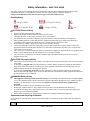
Handling Safety
<18 kg (<40 lb)
32–55 kg (70–120 lb)
18–32 kg (40–70 lb)
>55 kg (>120 lb)
>10º
CAUTION! Electrical Safety
•
•
•
•
•
•
•
•
•
Do not work alone under hazardous conditions.
High current through conductive materials could cause severe burns.
Check that the power cord(s), plug(s), and sockets are in good condition.
Use qualified service personnel to change the plug on the UPS and to install permanently wired equipment.
When grounding cannot be verified, disconnect the equipment from the utility power outlet before installing or
connecting to other equipment. Reconnect the power cord only after all connections are made.
Do not handle any metallic connector before the power has been disconnected.
Connect the equipment to a three wire utility outlet (two poles plus ground). The receptacle must be connected to
appropriate branch circuit/mains protection (fuse or circuit breaker). Connection to any other type of receptacle may
result in risk of electrical shock.
230 V models only: In order to maintain compliance with the Electro Magnetic Compliance directive for products sold in
Europe, output cords attached to the UPS should not exceed 10 meters in length.
230 V models only: Total leakage current from connected equipment and the UPS must not exceed 3.5 mA for a
pluggable A Type UPS.
CAUTION! Deenergizing Safety
•
•
If the UPS has an internal energy source (battery), the output may be energized when the unit is not connected to a utility
power outlet.
To deenergize a pluggable UPS, press the OFF button or switch to shut the equipment off. Unplug the UPS from the
utility power outlet. Disconnect the external batteries where applicable and disconnect the internal battery (see User
Manual). Push the ON button to deenergize the capacitors.
To deenergize a permanently wired UPS, press the OFF button or switch to shut the equipment off. Switch off the
utility circuit breaker that supplies power to the UPS. Disconnect the external batteries where applicable and disconnect
the internal battery (see User Manual).
WARNING! Battery Safety
•
•
•
•
•
This equipment contains potentially hazardous voltages. Do not attempt to disassemble the unit. The only exception
is for a UPS containing batteries. Refer to the battery replacement procedures detailed in the User’s Manual. Except for
the battery, the unit contains no user serviceable parts. Repairs are to be performed only by qualified service
personnel.
Do not dispose of batteries in a fire. The batteries may explode.
Do not open or mutilate batteries. They contain an electrolyte that is toxic and harmful to the skin and eyes.
To avoid personal injury due to energy hazard, remove wrist watches and jewelry such as rings when replacing the
batteries. Use tools with insulated handles.
Replace batteries with the same number and type of batteries as originally installed in the equipment.
Replacement and Recycling of Batteries
See your dealer or contact Rockwell Automation at 440-646-5800, for information on replacement battery kits and battery
recycling.
Be sure to deliver the spent battery to a recycling facility in the re placement battery packing material.
41063-260-01(1)
17