1
r
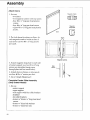
Save ThisManual
For Future Reference
owner's
manual
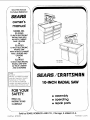
MODEL NO.
113.197411
10-1NCH ELECTRONIC
RADIAL SAW WITH
4_,-INCH CABINET
AND 2 DOORS
or
I
113.19761
113.197511
10-1NCH ELECTRONIC
RADIAL SAW
WITH 44-1NCH CABINET
AND 2 DOORS AND
CASTERS
or
113.197611
113.197411
10-1NCH ELECTRONIC
RADIAL SAW WITH
44-1NCH CABINET
AND 6 DRAWERS
Serial
Number
Model
SEARS / r.RRFT$ IViRN
:]nd serial numbers
may be found
on the left
hand side of the base.
You shculd record
both
model
and serial number
in
a safe place for future use.
FOR YOUR
SAFETY:
READ ALL
INSTRUCTIONS
CAREFULLY
\
10-1NCH RADIALSAW
• assembly
• operating
• repair parts
Y\
Sold by SEARS, ROEBUCK AND CO., Chicago,
Part No. SP5539
IL 60684 U.S.A.
Printed
in U.S.A,
Table of Contents
Section
Title
Safety
..........................
.........................................
Assembly
3
......................................
Controls
10
.......................................
Alignment
Digital
and Adjustment
Display
Electrical
Ripping
34
............................
37
...................................
Connections
Crosscutting
Cutting
Page
48
...............................
54
.....................................
57
.......................................
Aides
....................................
Accessories
75
..................................
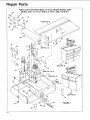
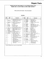
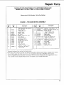
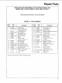
Repair
Parts
Index
.........................................
79
.....................................
ONE
one
to a defect
72
....................................
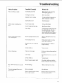
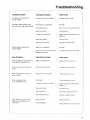
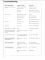
Troubleshooting
If within
69
.....................................
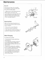
Maintenance
FULL
61
YEAR
year
from
in material
84
103
WARRANTY
the date
ON CRAFTSMAN
of purchase,
or workmanship,
Sears
this Craftsman
will repair
WARRANTY
SERVICE
IS AVAILABLE
BY SIMPLY
NEAREST
SEARS
SERVICE
CENTER/DEPARTMENT
UNITED
STATES.
This warranty
applies
only while this product
RADIAL
Radial
it, free
ARM
Saw fails due
of charge.
CONTACTING
THROUGHOUT
is used in the United
ROEBUCK
AND CO. DEPT. 698/731A
CHICAGO,
IL 60684
SEARS
THE
THE
States.
This warranty gives you specific legal rights and you may also have other
v,hich vary from state to state.
SEARS,
SAW
rights
TOWER,
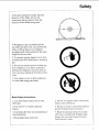
Safety
This manual has safety information
and instructions to help users eliminate or
reduce the risk of accidents and injuries,
including:
1. Severe cuts, and loss of fingers or other
body parts due to contact with the blade
2. Eye impact injuries, and blindness,
being hit by a thrown workpiece,
workpiece chips or pieces of blade
from
Major
Hazards
Three major hazards are associated with
using the radial arm saw for ripping. They
are outfeed zone hazard, kickback, and
wrong way feed.
This section only briefly explains these
hazards. Read the ripping and crosscutting safety sections for more detailed explanations of these and other hazards.
3. Bodily impact injuries, broken bones,
and internal organ damage from being hit
by a thrown work'piece
Outfeed
4. Shock or electrocution
Zone
Hazard
5. Burns.
_DANGER
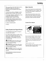
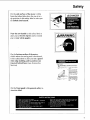
Safety Symbol and Signal Words
An exclamation
mark inside
the safety alert symbol.
a triangle
is
It is used to draw attention
to safety information in the manual and on the saw. It is
followed by a signal word, DANGER,
WARNING,
or CAUTION,
which tells
the level of risk:
_h, DANGER: means
mation is not followed
seriously
injured
if the safety inforsomeone will be
or killed.
Fingers
WARNING: mearks if the safety information is not followed someone could be
seriously
_
injured
CAUTION:
or killed.
means
mation is not followed
injured.
if the safety inforsomeone
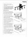
If you reach around the blade to the outfeed side when ripping, and try to hold
down or pull the workpiece
through to
complete a cut, the rotational
force of the
blade will pull your hand back into the
blade.
might be
Read and follow all safety information
and instructions.
Read
will be cut off.
and
structions
follow
under
the information
ripping
safety.
and in-
Safety
Kickback
Hazard
Kickback is the uncontrolled propelling of
the workpiece back toward the user
du ring ripping.
WARNING
The cause of kickback is the binding or
pinching of the blade in the workpiece.
Several conditions can cause the blade to
bind or pinch.
When a workpiece kicks back, it could hit
hard enough to cause internal organ injuu, broken bones, or death.
Read
and follow
structions
under
the information
ripping
KICKBACKItI_
and in-
safety.
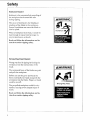
Wrong Way Feed Hazard
Wrong way feed is ripping by feeding the
workpiece into the outfeed side of the
blade.
kWARNING
The rotational force of the blade can grab
and pull the workpiece.
Before you can let go or pull back, the
force could pull your hand along with the
workpiece into the blade. Fingers or hand
could be cut off.
Wrong Way Feed
The propelled workpiece
could hit a bystander, causing severe impact injury or
death.
Read
and
structions
follow
under
the information
ripping
safety.
and
in-
Safety
Safety
Instructions
Read and follow all safety instructions.
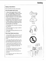
Personal
Safety Instructions
1. Wear safety goggles labeled "ANSI
Z87.1" on the package. It means the goggles meet impact standards set by the
American National Standards Institute.
Regular
eyeglasses
are not safety goggles.
2. Wear close fitting clothes, short
sleeved shirts, and non-slip shoes. Tie up
long hair. Do not wear gloves, ties, jewelry, loose clothing, or long sleeves. These
can get caught in the spinning blade and
pull body parts into the blade.
Safety Goggles
Dust Mask
3. Wear dust mask to keep from inhaling
fine particles.
4. Wear ear protectors,
you use saw daily.
5. Keep good footing
over-reach.
plugs or muffs if
and balance;
do not
Work Area Safety Instructions
Ear Protectors
1. Keep children, pets, and visitors out of
work area; they could be hit by a thrown
workpiece, workpiece
chips or pieces of
blade.
2. Turn saw off, remove yellow key, and
unplug before leaving work area. Do not
leave until blade has stopped spinning.
3. Make work area child-proof:
remove
yellow key to prevent accidental start-up;
store key out of sight and reach; lock
work area.
4. Keep floors clean and free of sawdust,
wax and other slippery materials.
5. Keep work area well lighted
cluttered.
and un-
6. Use saw only in dry area. Do not use in
wet or damp areas.
Safety
Saw Safety Instructions
1. Use guard, pawls and spreader according to instructions.
Keep them in working
order.
2. Routinely check saw for broken or
damaged parts. Repair or replace
damaged parts before using saw. Check
new or repaired parts for alignment, binding, and correct installation.
3. Unplug saw before doing maintenance,
making adjustments,
correcting alignment, or changing blades.
4. Do not force saw. Use saw, blades
accessories
and
only as intended.
5. tlave yellow key out and saw switched
off before plugging in power cord.
Workpiece
Safety Instructions
1. Cut only wood, woodlike or plastic
materials. Do not cut metal.
2. Cut only one workpiece at a time.
Stacking or placing workpieces edge to
edge can cause user to lose control of
workpiece.
6. Before turning on saw, clear table of all
objects except workpiece
to be cut and
necessary fixtures, clamps, or featherboards.
7. If blade jams, turn saw off immediately,
remove yellow key, then free blade. Do
not try to free blade with saw on.
8. Turn saw off if it vibrates too much or
makes an odd sound. Correct any problena before restarting saw.
9. Do not layout, assemble, or setup work
with saw on, or while blade is spinning.
10. Keep saw table clean.
11. Store items away from saw. Do not
climb on saw or stand on saw table to
reach items because
saw can tip over.
Safety
3. Rip only workpieces
diameter of the blade.
longer than the
Do not rip
workpieces
that are shorter than the
diameter of the blade being used.
4. Workpieces
that extend beyond the
saw table can shift, twist, rise up from the
table, or fall as they are cut. Support
workpiece with table extensions the same
height as the saw table.
5. To prevent
of extensions
tipping, support outer ends
with sturdy legs or an outrig-
ger.
6. Do not use another person to help support workpieces
or to aid by pushing or
pulling on workpieces,
because these actions can cause kickback. Use table extensions.
7. Use clamps or vice to hold workpiece.
It's safer than using your hands.
Blade
Safety
Instructions
I. Use only blades
3450 rpm.
marked
2. Use only 10" or smaller
blades.
3. Use blades
ting procedures.
and clean.
nut because
6. Do not turn saw on and off in rapid sequence because blade can loosen.
diameter
for their recommended
4. Keep blade sharp
5. Do not overtighten
blade
blade collar could warp.
for at least
cut-
7. Blade should stop within 15 seconds
after saw is switched off. If blade takes
longer, the saw needs repair. Contact
Sears Service Center.
Safety
On-Product
Safety
Labels
There are several safety labels on the saw.
They alert the user to hazards explained in
the manual and remind the user how to
avoid the hazard.
Note where
they are located
Read and follow
and instructions
the manual
instructions.
on the saw.
the safety information
in these labels. Refer
for detailed
explanations
to
and
On the outfeed side of the guard is this
safety label to alert you to wrong way feed:
ADANGERi
On the infeed
safety
label
to remind
(hold
side
to alert
of the guard
you to kickback,
you to lower
down)
is this
the guard
and
kWARNING
nose
for ripping:
KICKBACKI!II_
Safety
On the side surface of the motor, visible
from the infeed side when the saw is in a
rip position,
is this safety
to outfeed zone hazard:
Near
alert
the saw handle
you to thrown
you to wear
safety
On the bottom
visible
when
is this safety
when
edge
label
is this safety
objects
and
you
label
to
to remind
, WARNING
goggles:
surface
of the motor,
the cutting
label
tool is horizontal,
to alert
molding,
ting tool behind
to alert
DANGER
and
fence:
you use a guard
to position
(see
cut-
DANGER
Accessories
Section)
On the front panel
struction
label:
is this general
safety
in-
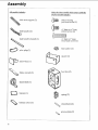
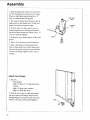
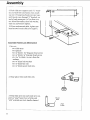
Assembly
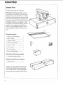
Identify
Parts
The following
Note:
Before
parts are included:
beginning
assembly;
that atl parts
are included.
ing any part,
do not assemble
your
Sears
part.
Sometimes
Service
Center
small
check
If you are misssaw.
Contact
to get the missing
parts
can get lost in
packaging
material.
packajng
until saw is put together.
Do not throw
away' any
Check
packagirN
for missing
parts
before
bzg Sea_'.
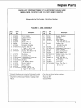
A complete
parts
list (Repair
Parts)
contact-
is"at the end of the manual.
list to identi_
part.
the number
A. Basic Saw Assembly
B. Rear
D. Fence
........... 1
.......................
(wooden)
E. Front Table
F. Trim
of the missing
Table ...........................
C. Spacer Table
Use the
1
1
................. 1
.........................
1
Cap ..............................
2
G. Cabinet
H. Loose
Box ........................
1
Parts Bags ................ *
Only models
with casters
I. Caster/Foot
include:
Bag or Box ...... 1
Only model with drawers includes;
J. Drawer
Box ..........................
1
*Number varies; bags can contain other
smaller bags. Note: To make assembly
easier, keep contents of each bag together,
and separate from contents of other bags.
10
G
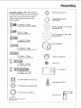
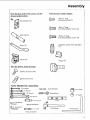
Assembly
All models
are given,
include:
three
numbers
the first is for the door model
easters,
the second
without
drawer
casters,
model.)
(_
(When
with
is for the door model
and the third is for the
©
#10
©
v'4"diam lock washer
(88/70/104)
v4" diam
long (76/64/96)
truss
headx _"
screw
# 10 x v2" long
pan head screw (1)
1/4"diam x _" long
pan head screw (2)
lock washer
(1)
_7/64"in. diam x w16"out. diam
flat washer (8)
5)
in. diam x s_" out.
flat washer
(5)
17/64"
hex bushing
diam
(1)
1/4"diam x _" long
pan head type AB screw (4)
QJlIF*llfq!lt
v'4" diam x _" long
cup point set screw (3)
rubber
bushing
1/4"diam x lvg'long
pan head screw (6)
spacer
(2)
illIHIll[Llllllqqq lll l l
v4" U-clip
(5)
(5)
v4" diam x 13/4"long
mounting screw (5)
_
1/4"diam square
lock nut (2)
leveling
foot
(2/4/2)
74" diam hex nut (88/70/104)
o)
a/8"diam hex nut (2/8/2)
slide arm (2)
____
tee nut (3)
11
Assembly
A]! models
Only
include:
the door
drawer
slide arm support
(2)
model
@[_
model
with casters
include:
#10
x _/8"long
pan head
screw (4)
v4" diam x 7/_6"long
slotted screw (4)
ck handle
(2)
]lHllLltlLllltllllltB
v4"diam x 1" long
truss head screw (2)
andle channel
(2)
(_)
flat washer
(2)
yoke plug (1)
spacer (2)
_
yellow key (1)
foot box (2)
_
blade wrench
handwheel
(2)
(1)
battery (1)
spring
%
battery cover (1)
smooth
%
12
(2)
grooved
pin (2)
pin (2)
and
the
Assembly
Only the door model with easters
drawer model include:
pin retainer
Only the door models
and the
_]]]_
(2)
include:
#6 xhead
_is"long
pan
screw (4)
#6 xhead
V2"long
pan
plastite screw (4)
foot rod (2)
_I_
#10
x V2"long
pan head
plastite screw (8)
magnetic catch with stop plate
(2)
_caster
(4)
Only the drawer
hinge (4)
model
includes:
0
0
drawer fastener (48)
_
Tools
grease packet (1)
Needed
for Assembly
7116" Wrench
--___
@
Socket
Extension
9/16"
Socket
1/2" Wrench
@
Socket
9/16"Wrench
Wrench
3/4 '' Socket
_,f
@
5/8"
Wrench
Level
ex Wrench
Medium Screwdriver
_n3er
Wrench
3
Framing
H
Phillips
Screwdriver
Square
I
13
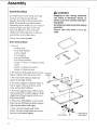
Assembly
Assembly
Steps
WARNING
Plugging in saw during assembly
can result in electrical shock, or
severe cuts from contact with spinning blade.
Do not plug in saw at anytime during
assembly.
Plug in saw only when it is to be
used.
It is important
for your safety and to get
accurate cuts that you put the saw
together according to these instructions.
Note: This manual covers three models.
Depending on the model saw, you will be instructed to skip some steps, or do extra
steps. The diffe.rences have to do with
whether the cabinet ha.s doors or drawers,
and whether or not it has casters.
Follow
these
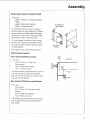
Build Cabinet
steps
in order.
Base
1. Set out:
-bottom shelf
-front shelf stiffener
-under support
-lower support
-re ar shelf stiffener
-four corner brackets
-sixteen v4" diam x v2" long truss head
screws
-sixteen vg' diam lock washers
-sixteen va" diam hex nuts.
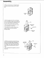
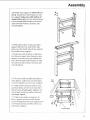
2. Put bottom shelf upside down so long
edge of raised (rear) side points do_m.
3. Put front shelf stiffener
against
inside
Rear Shell
Stiffener
and
front edge of shelf.
4. Put under support on shelf so holes in
end of support line up with two center
holes in front shelf stiffener.
5. Put lower support under shelf so holes
line up with holes in under support. Note:
Angled end of lower support will stick out
from front of shelf.
6. Place rear shelf stiffener so two center
holes line up with holes in under
and ends are inside shelf edges.
support
7. Insert screws through eight holes
shown. On end of each screw put washer,
then m_t, and wrench tighten.
14
Shelf
Lower Support
Angled End Of
Lower Support
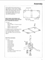
Assembly
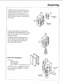
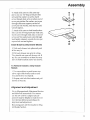
8. Put corner bracket in each corner, so
edges point up. Attach brackets to long
sides of shelf: use two screws per bracket
(insert screws through shelf); on end of
each screw put washer, then nut, and
wrench tighten. Note: Screws for short
sides wilt be in,_tatted later.
Long End of Shelf
\
Attach Casters (Only Models with
Casters; Door Model without Casters:
Go to "Assemble
Side Panels")
._,.,_
Long End of Shelf
Corner Bracket
1. Set out:
-four casters
-sixteen v4" diam x v2"long truss head
screws
-sixteen v'4"diam lock washers
-sixteen v_" diam hex nuts.
2. Attach
one caster to each corner
brack-
et: use four screws per caster (bzsert
screws through shelf); on end of each
screw put washer, then nut, and wrench
tighten.
Build Foot Assemblies
1. Set out:
-two foot boxes
-two foot levers
-two foot rods
-two
-two
-two
-two
pin retainers
grooved pins
smooth pins
washers
-two
-two
-t'our
-two
springs
leveling feet
# 10 x _/_"long pan head screws
_/s" diam hex nuts.
!5
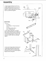
Assembly
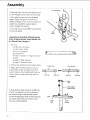
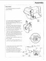
2. Place one foot box so C-shaped opening faces you and closed side is on your
left.
C-Shaped
Slot
3. With threaded end of foot rod facing
down, and smaller square opening facing
you, put rod through top opening of foot
box, and slide half way down into box.
Rod
Smaller Square
Opening
4. Put grooved pin through hole in foot
rod so grooved end faces out.
Grooved
5. On end of foot rod put washer then
spring. Push rod all the way down
through spring.
Pin
Washer And
Spring
6. With lever pointing towards left, put
foot lever through upper opening of "C",
through rod, and out other end of foot
box. Apply a few drops of SAE 10W-30
motor oil to area where lever and rod
meet.
7. Put smooth
foot lever.
16
pin through
hole at end of
Rod
Lever Points
Toward Left
Smooth Pin
Assembly
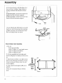
8. Pull foot lever forward
until smooth
pin sits in groove of foot box. Attach
retainer to rear of foot box: use two
pin
screws (insert screws through two smaller
holes of retainer; make sure smaller holes"
are on top).
Small Holes
On Top
Smooth Pin
In Groove
9. Screw nut to within v2" of bottom
of
leveling foot. Screw leveling foot into rod
until nut meets foot box. This completes
left foot assembly.
10. Repeat steps to build right foot assembly. Begin with closed side of foot
box to your right (step 2). Have lever
point toward right (step 6).
Attach Foot Assemblies
1. Set out:
-right side panel
-left side panel
-four v4" diam x 7/16"long slotted
screws.
!
2. Push foot lever on right foot assembly
down into lower opening of "C" to lock
foot assembly.
Lever
Locked
Down
Right
Foot
Assembly
17
Assembly
Foot
3. Identify
right
side panel
ter "R" stamped
near
4. Put right
assembly
edge
foot
of right
comes
"J" slot.
attach
foot assembly
screws
through
5. In similar
center
edge.
front
\
Use two screws
to panel
I
Assembly
let-
so foot lever
to
(insert
,fide panel).
way, attach
to left side
of rear
inside
side panel,
through
by locating
left foot assembly
panel.
Side
Panel
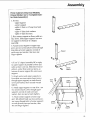
Assemble
and Install Slide Brackets
(Only Drawer Model; Door Model: Go
to "Attach Door Hinges")
%
1. Set out:
-twelve outer brackets
-t_velve center slides
-three rear supports
-grease packet
-tv, enty _a" diam x _/2"long truss head
screws
-twenty
-_enty
2. Grease
t/4" lock washers
v4" diam hex nuts.
top and bottom
3. Make twelve
of"center
slide brackets:
slides.
insert a
center slide all the way into each of 12
outer brackets, then slightly pull back on
center slide to make sure stop tabs are
engaged.
Center
Slide
Outer
/
/
Stop Tab
Stop Tab
Stop Tab
_
r_-......_ Short
Tabs
"---'-
4. Attach
three slide brackets
18
Rear Support
Solid Surface
to left side
of one rear support, in holes indicated:
use one screw per slide bracket (insert
screws" through lalger hole in slide bracket);
on end of each screw put washer, then
nut, and wrench tighten.
Bracket
Larger
Hole
Slide
Bracket
Rear Stop
Assembly
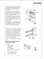
5. Position rear support, with slide brackets attached, inside right side panel, so
short tabs point up, and solid surface
faces front.
6. Attach rear support to side panel: use
two screws (insert screws through side
panel); on end of each screw put washer,
then nut, and wrench tighten.
7. Attach
slide brackets
Short
Tabs
_
-_
to front inside
edge of side panel: use three screws (insert screws through slide brackets); on end
of each screw put washer, then nut, and
wrench tighten.
8. Repeat steps 4-7, installing slide brackets to right side of another rear support
and attaching rear support, with slide
brackets attached, to left side panel.
9. Attach four slide brackets to remaining
rear support, one on each side of center
hole and one on each side of second hole
from top: use four screws (insert screws"
through larger hole in slide bracket); on
end of each screw put washer, then nut,
and wrench tighten. Set this" rear support
cL_idefor later use. Remaining two slide
brackets will be installed later.
10. Go to "Attach
Shelf."
J
Larger
Hole
Side Panels to Bottom
Assemble Side Panels(Only
Model without Casters)
Door
1. Set out:
-right side panel
-left side panel
-two spacers
-four leveling feet
-four vq" diam x 1/2"long truss head
SCreWS
-four v4" diam lock washers
-four 1/a"diam hex nuts
-eight _ia"diam hex nuts.
19
Assembly
2. Identify right side panel by locating letter "R" stamped near center of rear edge.
Position right side panel upright, so "J"
slot is at bottom and facing you.
%"a'2',
3. Put spacer inside front bottom edge of
side panel, so two holes face "J" slot and
large hole rests on bottom edge.
t'III
4. Attach spacer to side panel: use two
screws (insert screws through side panel);
on end of each screw put washer, then v4"
nut, and wrench tighten.
5. In similar
panel.
way, attach
spacer to left side
Spacer
6. Screw _W'nut onto each leveling
foot.
7. Insert leveling foot through bottom
hole at front and rear of each side panel.
On end of each leveling foot put another
_" nut and finger tighten until it meets
surface.
Attach Door Hinges
1. Set out:
-four hinges
-eight _/4"diam x v_" long truss head
screws
-eight 1/4"diam lock washers
-eight 1/4"diam hex nuts.
2. Attach two hinges to each side panel:
use two screws per hinge (in._ert screws
through hinge); on end of each screw put
washer, then nut, and wrench tighten.
2O
J-Shaped
Assembly
Attach Side Panels
to Bottom
Shelf
1. Set out:
-eight v4" diam x v2" long truss head
screws
-eight vg'diam lock washers
-eight W' diam hex nuts.
2. Put bottom
Angled End Of
Lower Support
shelf on floor so bottom
surface faces you and angled end of lower
support points up. Slide right side panel
into place so four holes in side panel line
up with four holes in bottom shelf.
3. Attach panel to shelf: use four screws
(insert screws through side panel); on end
of each screw put washer, then nut, and
wrench tighten.
4. In similar way, attach
Attach/Install
left side panel.
Casters:
1. Set out:
-two v4" diam x v>."long truss
head screws
-two 74"diam lock washers
-two 5_" diam hex nuts.
2. Attach spacers to bottom shelf: use one
screw per spacer (hzsert screw through
spacer); on end of screw put washer, then
nut and wrench tighten.
Model
Right Side
Panel
Spacers
D_oxlr _ITHOUT
Door
Bottom Side
Of Shelf
WITH
Casters
Side
Panel
Side
\,
View
®
I
Spacer
"_'-
Shelf
and Drawer;
1. Set out:
-two spacers
-two v4" diam x 1" long truss head
screws
-two 1/g'diam lock washers
-two 1/4"diam hex nuts.
2. Push foot levers down and towards outside so they will release and unlock foot
assemblies.
21
Assembly
3. Attach spacer between each foot assembly and bottom shelf: use one screw
per spacer (insert screw through foot assembly); on end of each screw put washer,
then nut, and wrench tighten.
Side
Panel
1" Long
\
Screw
/
[
_....----- Spacer
Attach
Skirts
1. Set out:
-two skirts
-ten v4" diam x vz" long truss head
screws
-ten v4"diam lock washers
-ten 1/4"diam hex nuts.
2. Turn cabinet right side up. Attach
skirts, across front and rear of cabinet, to
side panels: use four screws per skirt (insert screws through skirt); on end of each
screw put washer, then nut, and finger
tighten.
Rear
Skirt
_kirt
3. Put screw through hole at bottom rear
of right side panel and through raised
edge of bottom shelf. On end of screw
put washer, then nut, and wrench tighten.
Repeat for left side panel.
Righl Side
Panel
Shelf
Front
22
Assembly
Finish Cabinet (Only Door Models;
Drawer Model: Go to "Complete
Center Slide Assembly")
1. Set out:
-upper support
-center support
-eight 1/4"diam x 1/2"long truss head
screws
-eight v4" diam lock washers
-eight 1/4"diam hex nuts.
2. Rest center support on floor, solid surface down. Slide upper support into center support to form an "L" shaped
assembly.
3. Attach center support to upper support: use two screws (insert screws through
long sides of center support); on end of
each screw put washer, then nut, and
finger tighten.
_-
4. Turn "L" shaped assembly 90° to right,
so upper support is parallel to floor and
solid surface is on top. Slide into front of
cabinet, under front and rear skirts, so
bottom of center support fits onto lower
support.
5. Attach center and upper
front skirt: use two screws
through upper support); on
screw put washer, then nut
tighten.
supports to
(insert screws
end of each
and wrench
Support
Center
Support
Front
Skirt
\
Upper
Support
6. Attach upper support to rear skirt: use
two screws (insert screws through upper
support); on end of each screw put
washer, then nut and wrench tighten.
7. Attach center support to lower support: tilt cabinet back; use two screws (insert screws through sides of center support);
on end of each screw put washer, then
nut and finger tighten.
Center
Support
Lower
Support
23
Assembly
Attach
Doors
1. Set out:
-two doors
Magnetic
-two magnetic catches with stop plates
-four #6 x _/2"long pan head plastite
screws
-four #6 x ya" long pan head screws
-eight #10 x 1/2"long pan head plastite
screws.
Magnetic
Slop Plate
2. Put both doors face down on floor. At-
Doors
/\
tach magnetic catch to inside surface of
each door: use two #6 x v2" long screws
per catch.
f
!
¢
tJ
Magnetic Catches
3. Attach magnetic stop plate to each side
of center support: use two #6 x 3!g'long
screws per stop plate (insert screws
through plate and into small holes).
4. Attach doors to hinges on side panels:
use four #10 x 1/2"screws per door.
5. Go to "Attach Handwheel".
Complete
Center Slide Assembly
(Only Drawer Model)
1. Set out
-center support
-upper support
-rear support with four slide brackets
attached
-two slide brackets
-sixteen _" diam x v_" long truss head
screws
-sixteen v'4"diam lock washers
-sixteen l/4" diam hex nuts.
24
Catch
Side
Panel
c
Assembly
2. Position
rear support
so short
at top. Attach
four slide brackets
ter support
support
screws
each
wrench
(make
faces
through
screw
out):
sure
solid
use four
slide brackets');
put washer,
then
tabs are
to cen-
surface
screws
on end
nut,
of
(insert
of
and
tighten.
3. With solid surface on top, put upper
support between rear and center supports, so it sits inside tabs of rear support
and inside center support.
4. Attach two slide brackets at top: position them so larger holes line up on rear
support; use two screws per bracket (insert screws through slide bracket); on end
of each screw put washer, then nut, and
wrench tighten.
5. Tilt center slide assembly and slide inside cabinet, under front and rear skirts,
so center support rests on lower support.
6. Attach center slide assembly to front
and rear skirts: use tw'o screws per skirt
(insert screws through upper support); on
end of each screw put washer, then nut,
and finger tighten.
7. Attach center and rear supports to
lower support: use four screws (insert
screws through front and rear supports); on
end of each screw put washer, then nut,
and wrench tighten.
Front
Skirt
Center
Support
I
/
g
Lower
Support
25
Assembly
Assemble
Drawers
1. Set out:
-two 10" drawers
-two 6" drawers
-two 3" drawers
-six drawer fronts
-forty-eight
2. Slide drawer
drawer
fronts
fasteners.
down onto drawers.
3. From inside drawer surface, push
drawer fastener into each hole and i_to
drawer front.
4. Set drawers aside for installation
saw has been mounted.
Drawer
/
after
1. Set out:
-handwheel
-#10 x 1/2"long pan head screw
-# 10 lock washer
-hex bushing.
2. Put hex bushing
of handwheel.
3. Align hex bushing
into opening
on elevation
in back
shaft.
4. Put washer on screw; put screw into
hole in center of handwheel
and tighten
with screwdriver.
26
Drawer
/_
Q
Attach Handwheel
Front
°Drawe_
Fastener
Assembly
Mount
Motor
Motor
1. Loosen guard clamp screw and lift
guard off blade.
Guard
2. Use both blade wrenches in scissor action to loosen blade nut. Note:Arbor
shaft has left-hand
wise to loosen.
threa&.
Clamp
Screw
Turn nut clock-
3. Remove and set aside nut, blade collars and blade. They, wifl be re-installed
later during alignment and adjustment.
4. I_,ock rip lock. Turn handwheel
clockwise to raise radial arm about 3".
5. Remove styrofoam packing blocks, and
clean small pieces of styrofoam off saw.
I.ifl motor out of styrofoam base and set
on center channel of saw. Remove three
table sections and fence.
6. Remove
motor
lock nut and flat washer
from
support.
7. Slide bevel cncoder to top position so it
will fit into notch in plate index on motor.
8. Slide motor onto motor support.
sure motor is firmly in place.
Make
[_-____
_
9. Re-install
flat washer
Rip Lock
Motor
Lock
Nut
and lock nut.
Tighten lock nut and at same time move
bevel lock (located near saw handle)
back and forth. Do not over tighten nut.
Lock
Support
Washer
27
Assembly
10. Push bevel lock to left (locking direction) as far as it will go. Space between
casting and bevel lock should be about
1/16"-_
1/16" :
to increase space, unlock bevel lock then
tighten lock nut on motor support;
to decrease space, unlock bevel lock then
loosen lock nut on motor support.
_'_
Lock
11. Lock bevel lock. With tabs on outside,
insert one end of yoke plug into opening
in blade carriage, just behind bevel lock.
Push until plug snaps into place.
Mount
Basic Saw Assembly
1. Set out:
-basic
-eight
-eight
-eight
saw assembly
v4" diam x v2" truss head screws
v4" diam lock washers
v4" diam hex nuts.
2. Lift saw assembly by front edge and
column and place on cabinet so holes line
up.
3. Attach saw to cabinet: use eight screw's
(insert screws through saw frame); on end
of each screw put washer, then nut and
wrench tighten.
.L
!
I
4. Check
cabinet.
and wrench
tighten
all nuts in
5. Put saw in location where it will be
used.
28
|
k,
I
Cabinet
Bevel
Lock
Assembly
Adjust Leveling
Feet
_,
Note: If cabinet has casters; lock foot assemblies and make sure front cm'ters are
slightly off floor before adjusting leveling
feet.
1. It"cabinet rocks, adjust leveling
they rest on floor.
2. Rest a level on radial
feet so
arm. If arm is
WARNING
Saw must slant slightly towards rear
to keep blade carriage from rolling
forward.
Workpiece
or saw can
move unexpectedly
if cabinet rocks.
Fingers, hand or arm could be cut off
by blade contact.
Adjust leveling feet before
using
saw.
level or slants forward, adjust leveling
feet so arm slants slightly towards rear.
3. Only Door Model Without Casters:
wrench tighten top nut on each leveling
foot.
Attach Trim Caps
1. Line up plastic stubs on back of trim
caps with holes on front corners of frame
and snap into place.
Trim Cap
Attach
Lock
Handle
Channels
1. Set out:
-two lock handle channels
-two lock handles
-four v4" diam x lvs" long pan head screws
-four 1/4"diam lock washers
-four va" diam hex nuts.
2. Insert lock handles
in front of saw.
through
openings
3. Slide lock handle channel, open side
facing down, onto each lock handle and
attach: use two screws per channel (hzsert
screws through lock handle channel); on
end of each screw put washer, then nut
and wrench tighten.
\
29
Assembly
Attach
Slide Arm Supports
1. Set out:
-two slide arm supports
-four v4"diam x _" long pan head type
AB screws
-front table.
2. Identify top and bottom of table: top
has countersunk
holes. Place table bottom side up.
3. Attach slide arm supports, solid sides
down, to table: use two screws per support; tighten, but not fully, because support will have to be adjusted later.
Install Front Table
1. Set out:
-three tee nuts
-five rubber bushings
-five 1/4"U-clips
-five 1/4"diam x 1_'4"long mounting screws
-two v4"diam x 1/2"long truss head screws
-three 1/4"diam x 7/8"long cup point set
screws
-five _7/_"in. diam x _/8"out. diam flat
washers
-two 17/64"in. diam x 9/16out. diam fiat
washers
-two v4" diam lock washers
-two 1/4"diam hex nuts.
Tee
Nut
2.With front table still bottom side up,
hammer tee nut into each leveling hole.
Leveling
3O
Holes
Assembly
3. Snap one U-clip onto left side of center
channel, so hole lines up with hole in
channel. Snap remaining four U-clips
over holes in sides of saw frame.
U-Clip On
Center Channel
U-Clips
U-Clips
4. Put 17/64"in. diam x s_s'' out. diam washer
on each W4" long mounting
Table Rail
screw.
5. Stand table on edge. Put mounting
screws, with washers attached, into each
of five mounting holes (insert screw
through table top); on end of each screw
put rubber bushing.
Rubber
Grommet
€
Mounting
Holes
Mounting
Holes
6. Place
table,
mounting
clips.
screws
Note:
beyond
line up with holes
Table
will extend
about
1"
Leveling
mounting
heads
sun" rubber
8. Start
leveling
bushings
hole
hex wrench
with table.
screws
just touch
cup point
and
Leveling
Holes
in U-
trim caps.
7. Tighten
until
top side up, on saw so
Front Table
On Front Edge
table.
into U-clips
Note:
Make
are not squeezed.
set screw
through
into tee nuts.
to tighten
screws
Use
until
each
v_"
flush
31
Assembly
9. Push slide arm supports until "L" brackets are flush with saw frame, then attach:
use one V2"long truss head screw per support (insert screw through "L" bracket); on
end of each screw put 17/d' in. diam x 9h6
out. diam flat washer, then lock washer,
then nut and wrench tighten.
10. From underneath
table, tighten pan
head screws in each slide arm support.
Assemble
L
Table Lock Mechanism
1. Set out:
-two siide arms
-two spacers
-two v4" diam x lye" long pan head screws
-two 14" diam x s_" long pan head screws
-six wd' in. diam x _46out. diam flat
washers
-two v4" diam lock washers
-two v4" diam hex nuts
-two v4" diam square
2. Snap spacer
lock nuts.
into each slide arm.
÷
3. Drop slide arm into each slide arm support so "nose" faces front of table and
"arm" extends over lock handle channel.
Fronl
Of Saw
32
Assembly
4. Attach slide arms to slide arm supports: use one 1W' long screw per slide
arm; put fiat washer on screw; insert
screw through slide arm; on other end of
screw put another flat washer; put screw
through slide arm support; on end of
screw put lock washer, then hex nut and
wrench tighten.
5. Attach
slide arms to lock handle
!
chan-
nels: use one _" long screw per slide arm;
insert screw through slide arm; on end of
screw put flat washer; put screw through
lock handle channel; on end of screw put
square lock nut and tighten.
Install Drawers
(Only Drawer
1. Slide each drawer
all the way in.
Model)
into place and push
2. Pull each drawer out as far it will go.
They should not come all the way out. If
any do, use screwdriver to bend out stop
tabs on slide brackets and re-test drawer.
To Remove
Model)
Drawers
(Only
Drawer
1. Llse screwdriver to push in one stop
tab on right slide bracket and at same
time pull drawer out slightly.
2. Repeat with left slide bracket
drawer all way out.
Alignment
and pull
and Adjustment
Go to Alignment
and Adjustment
Section
and follow all instructions.
You cannot
use the saw until it is aligned and adjusted. It may be helpful to read the Controls Section before proceeding with
alignment and adjustment.
Reinaining
parts will be installed
tal Display Section.
in Digi-
33
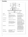
Controls
Miter
Lock
Digital
Display
On-Off
Switch
Yellow
Key
Bevel
Handwheel
Lock
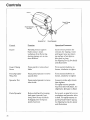
Function
Operation/Comments
Miter Lock
Frees radial arm to move;
locks in any desired position;
pre-set indexed positions at 0°,
45 °, -45 °
Pull Ollt and towards right to
unlock, push to lock
Hold in unlocked position
while moving arm
On-off
Switch
Turns
Pull on, push off
Requires yellow key
Yellow
Key
Allows
Bevel lock
Frees
motor
on/off
saw to be switched
motor
on
to rotate;
locks in any desired position;
pre-set indexed positions at
0°, 45°, -45 °, 90°, -90 °
Handwheel
Raises/lowers
radial
arm
Insert into on-off switch
Remove after turning saw off
Move towards right to unlock,
towards left to lock
Support motor before unlocking because it can swing down
quickly. Hold in unlocked position while moving motor
Turn clockwise
counterclockwise
to raise,
to lower
To fold handle into wheel,
squeeze red plastic ears and
push handle; pull handle out
until ears click into place
Table
Digital
34
Lock
Display
Frees table sections to allow
fence changing
Tells position of blade and
arm at touch of a button
Pull to unlock,
push to lock
See Digital Display Section
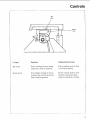
Controls
Rip
Lock
Swivel
Lock
Rip l.ock
Swivel
Lock
F_nncti_
Operation/Comments
Frees carriage to move along
radial arm; locks in position
Pull
Frees blade carriage to rotate
between rip and crosscut positions; locks in position
Pull to un]ock; push to lock
Hold in unlocked position
while moving blade cwriage
Lock
to unlock,
before
push
to lock
ripping
35
Controls
Guard
Guard Clamp
Screw
Pawls/Spreader
Wing Nut
Spreader
Nut
Pawls/Spreader
CxmU_
Function
Operation/Comments
Guard
Partially protects against
blade contact; keeps
workpiece from fluttering
during ripping; acts as sawdust deflector
Lock in level position for
crosscut; for ripping, rotate
until guard nose just clears
top surface of workpiece,
then lock in place
See Ripping Set- Up for details
and illustrations
Guard Clamp
Screw
Frees
blade
Turn counterclockwise
Pawls/Spreader
Wing Nut
Frees pawls/spreader
up and down
to move
Spreader
Frees pawls/spreader
side to side
to move
Nut
guard to rotate
about
loosen,
clockwise
clockwise
36
Reduce kickback by keeping
kerf open (spreader function); slow or stop kickback
by digging into workpiece
(pawls function)
to
to tighten
Loosen to make adjustment,
then tighten.
For safety reasons spreader
must be in line with blade. See
Alignment:
Pawls/Spreader
to tighten
Turn counterclockwise
loosen,
to
Spreader
to Blade
Set as unit, so pawl is level on
workpiece and spreader rides
in kerr. For safety reasons set
pawls/spreader
before ripping,.
See Ripping Set- Up for details
and illustrations
Alignment and Adjustment
This section applies to all three models
covered by this manual. The saw and
blade must be aligned correctly for two
reasons:
WARNING
Plugging in saw during
alignment
could result in accidental
start-up
and severe cuts from contact with
1) to prevent binding of the blade and
workpiece, which can cause jams, kickbacks, or thrown workpieces;
2) to make accurate
Alignment
spinning blade.
Do not plug in saw at any time during
alignment or adjustment.
Plug in saw only when it is to be
used.
cuts.
and Adjustment
Steps
The following alignments
and adjustments
must be made in order. If you miss an adjustment, you must go back, make the
missed adjustment,
and repeat all steps
from that point on.
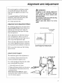
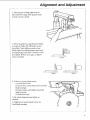
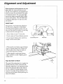
Check Framing Square
This Edge Must
Be Straight
I'-
....
1
1
These adjustments
are like fine tuning a
piece of equipment.
Often, a series of
steps must be repeated more than once in
order to get the adjustment
right.
There are many adjustments
to make. Because some adjustments
may be awkward,
you may want to ask someone to help you.
Before you start, make
squ_re is true.
Adjust
Column
The combined
I
I
Draw
Light
Line On Board
Along This Edge
I
j
LJ
/
Should Be No Gap Or Overlap Here When
Square Is Flipped Over In Dotted Position
sure the framing
Support
goal of this adjustment
a) to eliminate looseness between
column and column support, and
b) to make raising and lowering
arm a smooth and firm action.
is:
the
the radial
1. ix3ck radial arm at 0° miter.
2. Raise and lower radial arm a few turns
in each direction. Movement shouId be
smooth but firm.
If movement seems difficult, slightly
loosen (less than v_ turn) four bolts at
rear of colurma support.
37
Alignment
and Adjustment
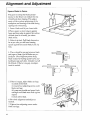
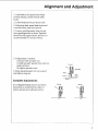
3. Feel for movement
between
column
and column support: place index finger of
one hand against column and column support; use other hand to push end of raddial arm side to side and up and down.
If there is no movement, no further adjustment is needed.
If there is movement,
slightly tighten
(less
than _ turn) four bolts at rear of column
support.
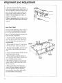
Level Front Table
The goal of this adjustment
is to make the
front table flat and parallel to the radial
arm, so that when the blade is installed,
there will be equal clearance between the
blade and table at all points.
1. Loosen all three cup point set screws
until they do not touch base. Make sure
five mounting screws are snug but not
overtightened.
2. Raise radial
at 90 ° bevel
arm about 3". Lock motor
(arbor
shaft points
Cup Point
Set Screws
Cup Point
Set Screw
down).
3. Draw two lines on table, one over each
lock handle channel/slide
arm support
area.
4. Unlock rip lock and pull blade
forward as far as it will go.
carriage
5. Unlock miter lock, move radial arm
until center of arbor shaft is directly over
a line. Mark that point on line.
6. Push blade carriage to rear and mark
similar point at rear of line. Mark other
line in same way.
7. Find lowest of four marked points:
measure distance between arbor shaft
and table (greatest distance identifies"
lowest point). Lower arbor shaft until it
just clears table at lowest point.
38
Mounting
Screws
Mounting
Screws
Alignment and Adjustment
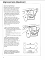
8. Without changing elevation of radial
arm, position arbor shaft, in turn, over
each of three remaining marked points.
Lower or raise table until arbor shaft just
clears table at those points:
to lower table: tighten mounting screws
to raise table: tighten cup point set
screws.
Check for equal clearance at all four
points.
\
\
k
\
\
9. Place rear table on its edge, across
front of table. Check for gap between
sufaces. If there is more than 1/32"gap,
close gap by tightening center mounting
screw and/or cup point set screws.
10. Similarly, check for gap across rear of
table and adjust as needed.
Square
Crosscut
Travel
The goal of this adjustment
is to make accurate crosscuts. To do so, the radial arm
must be perpendicular
to the fence, otherwise, there will be a slight miter angle in
all crosscuts.
I. I_ock radial
arm at 0° miter.
2. Lock motor
points down).
at 90 ° bevel (arbor
shaft
3. Lower radial arm until arbor shaft is
slightly above
table.
4. Unlock rip lock. Move blade carriage
until arbor shaft is at rear edge of front
table.
5. Place framing square so long side is off
rear edge of table, and short side just
touches arbor shaft. Hold square in place,
grasp saw handle and pull blade carriage
forward. Arbor shaft should just touch
square at all points. If it does, no adjustmerit is needed.
Framing
Square
39
Alignment and Adjustment
6. If arbor
shaft
square,
adjust
to move radial
two socket
tighten
head
screws
radial
two socket
tighten
toward
two screws
7. When
arbor
at all points,
few times.
then
Loosen
left, loosen
on left, then
on right. Note:
Loosen
equally.
shaft just touches
raise
and
If movement
ly and equally
loosen
on right,
on left. Note:
screws
screws
right,
from
equally.
arm
head
and tighten
into or away
screws
two screws
and tighten
to move
moves
radial arm:
arm toward
loosen
lower
square
radial
is difficult,
all four
arm
a
slight-
socket
head
screws.
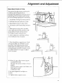
Install Blade
1. Lock rip lock.
2. Raise
radial arm. Lock motor
bevel (arbor
at 0°
shaft horizontal).
3. On arbor shaft put blade collar, then
blade, then second blade collar, then
blade nut. Note: Concave surfaces of
blade collars rest against blade. Make sure
directional arrow on blade is on outside
and points clockwise.
4. Use blade wrenches
in scissor action to
tighten nut. Note: Arbor shaft has lefthand threads. Turn nut counterclockwise
to tighten. Do not overtighten nut because
this can cause blade collar to warp and
blade to wobble during cutting.
Square
ting
Blade to Table for Crosscut-
The goal of this adjustment
blade perpendicular
to the
crosscuts will be accurate;
crosscuts will have a slight
is to make the
table so that
otherwise all
bevel angle.
1. I_wer blade until it just clears table.
Lock bevel, miter, rip, and swivel locks.
4O
Alignment
and Adjustment
2. Place square so long edge rests on
table and short edge rests against blade
surface, not on a tooth.
3. There should be no gap between blade
and square. Note: Not all blades are perfectly flat. Check different points along
blade surface by making quarter turns and
looking for gap each time. Consider overall
fit of blade. If there is no gap, no adjustment is needed.
Correct
t
Wrong
I
wrong
4. If there is a gap, adjust motor:
i) unlock bevel lock
ii) loosen four socket head screws behind
blade carriage
iii) move motor until blade rests flush
against square
iv) lock bevel lock.
5. Re-check
needed.
alignment
and adjust as
6. Tighten four socket head screws behind blade carriage.
@
41
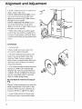
Alignment
Square
and Adjustment
Blade to Fence
The goal in setting the blade perpendicular to the fence is to reduce the risk
of kickback when ripping. This adjustment will also reduce splintering of the
workpiece and burning of the kerf during
ripping and crosscutting.
1. Lower blade until it just clears table.
2 Place square so short edge is against
fence and long edge is against flat surface
of blade (not on a tooth), just above
blade collar.
3. Unlock rip lock. Pull blade forward as
far as you can, yet still have framing
square against fence and blade. Lock rip
lock.
Correct
4. There should be no gap between blade
and square. Note: Not all blades are perfectly flat. Check different points along
blade surface by making quarter turns and
looking for gap each time. Comider overall
fit of blade. If there is no gap, no adjustment is needed.
5. If there is a gap, adjust blade carriage:
i) unlock swivel lock
ii) loosen four adjusting screws under
blade carriage
iii) grasp saw handle and move blade
carriage until blade rests flush against
square
iv) lock swivel lock.
6. Re-check
needed.
alignment
7. Tighten four adjusting
blade carriage.
42
and adjust as
screws under
I
!
L__
Wrong
Wrong
I
I
I
Alignment and Adjustment
Square
Blade to Table for Ripping
The goal of this adjustment
is to make the
blade perpendicular
to the table so that
rip cuts will be accurate; otherwise all rip
cuts will have a slight bevel angle.
1. [x)ck blade in out-rip position (blade
towards table front, motor towards
column). Lock rip lock.
2. Raise radial
arm to allow clearance
/
for
square.
3. Place square so long edge is on table
and short edge is against blade (not on a
tooth), beside blade collar.
,
4. There should be no gap between blade
and square. Note: Not all blades are perfectly flat. Check different points along
blade surface by making quarter turns and
Iooking for gap each time. Consider overall
fit of blade. If there is no gap, no adjustment is needed.
Correct
Wrong
5. If there is a gap, adjust rear carriage
bearing (which is visible when you go to
rear of saw and look up under radial arm-carriage bearing rides on central track):
i) hold bolt in place and loosen nut on
bearing
ii) rotate bolt until gap closes
iii) hold bolt in place and tighten nut.
6. Re-check
needed.
alignment
and adjust
Molor
Wrong
Rear
Carriage
Bearing
as
43
Alignment
Adjust Carriage
and Adjustment
Bearings
The goal of this adjustment
is to eliminate
looseness between the carriage bearings
and the radial arm. The blade carriage
should roll freely along the entire length
of the radial arm, but with some resistance.
1. With blade still locked in out-rip position, unlock rip lock and move blade carriage to rear as far as it will go.
2. From front of saw, look up under
radial arm to identify front carriage bearing. With thumb and index finger, get
pinch-hold
inside groove of bearing.
Apply force to bearing and at same time,
pull blade carriage forward. Force should
not stop bearing from turning while carriage is moving.
3. If you can stop bearing from turning
while carriage is moving, adjust bearings:
i) position blade carriage for good access
to front and rear bearings
ii) lock rip lock
iii) hold front bearing bolt in place and
loosen nut
iv) rotate
nut.
bolt a few degrees,
then tighten
Note: Carriage bearings have eccentric
bolts. High side of each bolt is marked by
an arrow. Adjust rear carriage bearing
same amount, but in opposite direction, as
you adjust front carriage bearing.
Note: Do not overtighten, gh, ertightening
can cause blade carriage to move with difficulty and will reduce life of track and
bearings.
OK Point Up
Both Arrows
OKpoint Down@
4. Before proceeding
to next section,
repeat steps to Square Blade to Table for
Ripping, because adjusting carriage bearings affects that alignment.
44
One Arrow Points Up
One Arrow Points Down
Alignment and Adjustment
Make Blade Parallel to Table
The goal of this adjustment is to keep the
workpiece from being thrown or
damaged. This adjustment will also reduce
splintering of the workpiece and burning
of the kerf during ripping and crosscutting.
1. Lock blade in straight
2. Pull blade forward
crosscut
and lock rip lock.
3. Raise blade at least 2" above
4. lock
tal).
motor
position.
table.
at 90 ° bevel (blade
horizon-
5. Place square so long side is on table
under right side of blade, and short side
hangs down vertically at front of saw.
Push edge of square against fence
Correct
Motor
6. [x)wer radial arm until blade surface,
not a tooth, just rests on square.
7. There
and
should
square.
fectIy flat.
blade
looking
be no gap between
Note:
Check
surface
Not all blades
different
points
by making
for gap each
fit of blade, if there
ment is needed.
quarter
tbne.
blade
are per-
Wrong
Wrong
along
turns and
Consider
overall
is no gap, no adjust-
11
8. if there is a gap, adjust motor support:
i) unlock bevel lock
ii) loosen two screws on back of motor
support
iii) move motor support until blade rests
flush against square
iv) lock bevel lock.
9. Re-check
needed.
alignment
10. Tighten
motor
and adjust
support
as
screws.
45
Alignment
Blade
alignment
plet_
Note:/t
odically
insure
check
and adjustment
is important
alignment
accurate
of cutting
and Adjustment
in one plane
ment
in other planes.
be perfectly
aligned
not another.
improve
Be aware
ment
com-
and adjustment
cuts and
procedures.
are
that you peri-
necessarily
Thus,
to
the safety
that align-
affects
the blade
alignmay
for one tape of cut but
Install Guard
The guard is a very important
safety feature. It covers a large part of the blade
and helps protect against severe cuts. Always use the guard and adjust it according
to instructions
for the type of cut.
!©
1. Raise blade at least 5" from table.
2. Lock motor
at 0° bevel (blade vertical).
3. Loosen guard clamp screw until it no
longer touches metal plate.
Guard Clamp Screw
Metal
Plate
4. Place guard over blade so guard clamp
screw is towards table front. Guard will
fall into place when ridge on inside of
guard slides into slot on motor.
5. Adjust guard to make sure bottom
edge is parallel to table. Tighten guard
clamp screw.
Align Spreader
to Blade
The goal of this adjustment
is to make the
spreader directly in line with the blade.
Spreader alignment
is an important safety
factor. The spreader rides in the kerf of
the cut workpiece
during ripping to help
keep the two sides of the workpiece from
pinching on the blade. Blade pinching is a
cause of kickback.
46
_.
Parallel
Alignment
and Adjustment
1. Lock blade in in-rip position (blade
towards column, motor towards table
front).
2. Lower blade until it just clears table.
3. Unlock
it touches
rip lock, move blade back until
fence, and lock rip lock.
4. Loosen pawls/spreader
wing nut and
lower pawls/spreader
to fence. Spreader
should rest flat against fence, and one set
of pawls should rest on top of fence.
5. If adjustment
is needed:
i) loosen both spreader nuts
ii) slide spreader against fence and rest
pawls on fence
iii) tighten spreader nuts.
Correct
Spreader
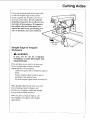
6. Raise pawls/spreader
and tighten wing nut.
unit up to guard
Pawl
Saw
Fence
Blade
Table
Complete
Adjustments
Go to Digital Display Section and follow
instructions
to irkstall battery, align encoders, and set zero reference points.
Wren(
Wrong
F
47
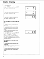
Digital Display
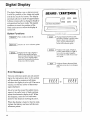
The digital display runs on battery power.
It tells the position of the blade and radial
arm at the touch of a button. The display
automatically
turns itself off approximately three minutes after a change in blade or
arm position has been made. The system
continues to track the position of the
blade and arm even when the display is
turned oft'.
Button
NL _,A/RS/ CRRFTSMRN
['=73
ELECTRONtC
MEASUREMENT
[/'
Functions
I ON/OFF
REF SET]
I Turns
TO LOCI
display
on and off.
[
ELEV
BEVEL
¥_LLOW
_E¥
Displays distance between table
and blade. Display is positive when
blade is above zero reference
point; negative when blade is
below zero reference point.
Used to set "zero" reference points.
I MITER
[
]
_[=OVE
Displays bevel angle. Display is
positive when motor has been
moved counterclockwise from zero
reference point; negative when
motor has been moved clockwise
from zero reference point.
] Displays miter angle. Display is
positive when blade is to right of
zero reference point; negative
when blade is to left of zero reference point.
:' ] Displays distance between blade
and fence in in-rip or out-rip positions.
Error
Messages
The zero reference points you set according to the instructions
later in this section
will be stored in memory at all times,
whether the display is on or off. If an error
occurs, you will see either of these messages displayed.
An error can be caused by sudden movement of the radial arm or blade carriage
when the electronic display is off. When
this happens, reset the zero reference
point for the function showing the error.
When the display is faded or hard to read,
replace the battery and reset all the zero
reference points.
48
EJ- C.C£" E 1
or
I
C
Cl2.U
!-_CJ-
Digital Display
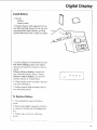
Install Battery
1. Set out
-battery
-battery.
cover.
2. Position battery with angled corner on
top right and slide battery all the way into
opening behind digital display, pushing
slightly downward until it snaps into place.
3. Look at display. It should look like this:
If it shows nothing, push in and slightly
upwards on battery to remove it, then reinstall.
If there still is no display, remove battery, wipe off contacts, then re-install.
If there is still no display, try a new 6V
alkaline battery or contact Sears.
4. When display shows correctly,
tery cover into place.
snap bat-
5. Follow steps to align encoders
zero reference points.
and set
To Replace
Battery
I. lJse screwdriver
cover.
to pry off battery
2. Push in and slightly upwards on battery
to remove it. Install new 6V alkaline batterv.
3. Follow steps to set zero reference
poi nts.
49
Digital Display
Align
Encoders
Miter Encoder
1. Turn display
on.
2. Lock radial arm at 0° miter.
3. Push MITER
button.
4. Push REF SET button.
read:
5. Unlock
Display will
miter lock, move radial arm to
right until it snaps into pre-set indexed
position and lock miter lock. Display
should read:
6. Unlock miter lock, move radial arm to
left until it snaps into pre-set indexed
position, and lock miter lock. Display
should read:
7. If display reads as it should,
coder is aligned correctly---no
is needed.
miter enadjustment
8. If display does not read as it should:
i) unscrew two screws from back cover of
radial arm, and remove cover
ii) unlock miter lock, move arm to right
until it snaps into pre-set indexed position, and lock miter lock
iii) loosen miter encoder mounting
screws inside rear of radial arm to allow
encoder to slide side to side
iv) slide or slightly tap encoder until
display reads 45 °
v) tighten miter encoder mounting
screws.
9. Repeat steps to align miter encoder.
When display reads as it should, re-install
back cover.
5O
I
I
MIT
"1
. _mJ
_I.U
J. U
I
Screws
Encoder
Digital Display
Bevel Encoder
1. Turn display on.
2. Lock radial arm at 0° miter. Lock
motor at 0° bevel.
3. Push BEVEL
button.
4. Push REF SET button.
read:
Display will
BEv
V!
•U
5. Support motor, unlock bevel lock,
move motor counterclockwise
until it
£1.U
snaps into pre-set indexed position and
lock bevel lock. Display should read:
[
6. Support motor, unlock bevel lock,
move motor counterclockwise
until it
snaps into next pre-set indexed position
(blade horizontal)
and lock bevel lock.
Display should read:
BEV
q'-"-'I
U.U
7. If display reads as it should, bevel encoder is aligned correctly--no
adjustment
is needed.
8. If display does not read as it should:
i) unlock bevel lock, move motor clockwise until it snaps into pre-set indexed
position, and lock bevel lock
ii) loosen bevel encoder screws on
backside of blade carriage to allow
encoder to slide side to side
Bevel
Encoder
Screws
Bevel
iii) slide or slightly tap encoder until
display reads 45 °
iv) tighten bevel encoder screws.
9. Repeat
steps to align bevel encoder.
Set Zero
Bevel,
Reference
Miter, and
Points
For
Elevation
1. Set blade in straight crosscut position
(0 ° miter) (0 ° bevel). Lower blade until it
just touches table. Note: This i_ the usual
blade position for settb N these zero reference points.
51
Digital Display
2. Turn display
on.
3. Push MITER button, then push REF
SET button. Display will read:
I
4. Push BEVEL button, then push REF
SET button. Display will read:
5. Push ELEV button, then push REF
SET button. Display will read:
Set Zero Reference
Rip
MIT
REV
1"1 I I
I
ELE
Point For In-
1. Put fence in front position
table locks.
and lock
2. Lock blade in in-rip position (blade
towards column, motor towards table
front).
3. Unlock rip lock, push blade
fence, and lock rip lock.
against
4. Push RIP button, then push REF SET
button. Display should read:
If it reads O-RIP instead of RIP, push
RIP button then push REF SET button.
If display reads 10.00 instead of.00, push
REF SET button.
Set Zero Reference
Out-Rip
Point For
1. Unlock rip lock and pull blade
from fence.
away
2. Unlock table locks, move fence to rear
position, and lock table locks.
3. Lock blade in out-rip position (motor
towards column, blade towards table
front).
52
,O1
1
.UU
Digital Display
4. Position blade 10" from fence, as
measured to nearest tooth, and lock rip
lock.
Blade
Fence
5. Push RIP button, then push REF SET
button. Display should read:
If it reads RIP instead of O-RIP, push
RIP button, then push REF SET button.
If it reads .00 instead of 10.00, push REF
SET button.
Conversion
!
t J-I I-I I-!
o..,, I U.U U
!
Table
Decimal equivalents
to nearest hundreth
of fractions,
inch:
rounded
.06
.09
.03
.12
19
.22
.!6
.25
.31
.34
38
44
.47
50
(_
,ioo
53
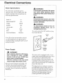
Electrical
Motor
Connections
Specifications
The AC motor
,_
used in the saw is a
capacitor-start,
non-reversible
type, The
models covered in this manual have the
following
specifications:
WARNING
If not properly grounded, this power
tool could cause electrical shock,
particularly when used in damp locations.
WARNING
Rated H P.
If electrical shock occurs, your reaction to ShOCk could bring hands into
contact with blade.
1,5
Max Developed H.P.
Voltage
2.75
120/240
Amperes
,_
12/6
Hertz (cycles)
To avoid electric shock or fire, immediately
replace
worn, cut, or
damaged power cord.
60
Phase
Single
RPM
345O
Arbor Shaft Rotation
WARNING
The unit is wired for 120V and has a plug
that looks like this:
Clockwise
3-Prong
Plug
Note:
If saw does not start when
on, immediately
Troubleshooting.
destroy
switched
turn saw off and refer to
Leaving
the switch
on will
the motor.
O
Grounding
Prong
Power
,_
Supply
Outlet
WARNING
Saw is factory wired for 120V operation.
Connect
to 120V, 15-AMP
branch circuit and use 15-AMP time
delay fuse or circuit breaker.
Failure to connect in this way could
result in injury from shock or fire.
The saw must be properly grounded. Not
all outlets are properly grounded. If you
are not sure that your outlet is properly
grounded, have it checked by a qualified
electrician.
54
Properly
Grounded
The power tool is equipped with a 3-conductor cord and grounding type plug listed
by Underwriters'
Laboratories.
The
ground conductor
has a green jacket and
is attached to the tool housing at one end
and to the ground prong in the attachment
plug at the other end.
The plug requires a mating 3-conductor
grounded type outlet as shown above. If
you have an outlet that is of the 2-prong
type, it is recommended
that you have a
qualified electrician replace it with a
properly grounded 3-prong outlet.
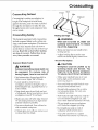
Electrical Connections
_k WARNING
To maintain proper tool grounding,
whenever outlet you are planning to
use for this power tool is of 2-prong
type do not remove or alter grounding prong in any manner.
An adapter is available for connecting
the
plug to 2-prong receptables.
The green
grounding lead extending from the adapter must be connected to a permanent
ground such as to a properly grounded
outlet box.
Extension
Grounding
Lug
3-Prong
Plug
/
_W7
\
_
/
Make
Sure
This
Gonnec_d
1_
a2T ll
Is
To A,
Koown rou°o
2-Prong
Adapter
,_
Receptacle
WARNING
Adapter illustrated is for use only if
you
already
have
a properly
grounded 2-prong receptacle.
Cords
Wire Sizes Required (AWG #)
The use of any extension cord will cause
some loss of power. Determine
the minimum wire size (American
Wire Gage No.
(AWG#))
extension cord. Use only 3wire extension cords with 3-prong grounding type plug and 3-pole receptacles
which
accept the tool's plug.
Cord
Length
0-25 ft
26-50 ft
51-100 ft
Note:
120V
240V
No. 14
No. 12
No. 10
No. 16
No. 14
No. 12
The smafler the gauge number,
the cord. For circuits farther
Motor
Protection
& Reset
The motor protector opens
circuit and stops the motor
motor temperature
exceeds
the motor is overloaded,
or
condition exists.
ttre heavier
away from the electrical
circuit box, wire size must
be h_creased
tionately
voltage to the motor.
to deliver ample
propor-
Button
the power line
when the
a safe level,
a low voltage
Manual
Reset
When the protector activates, immediately turn saw off, remove yellow key and
wait for motor to cool. Push red re-set button and listen/feel for click to indicate
protector is re-set. If you do not hear/feel
a click, motor is still too hot. Wait a while
longer and repeat.
55
Electrical
To Change
A.C.
Connections
Motor
Voltage
to 240
Under normal home workshop conditions,
if full voltage is supplied to the motor, the
saw will operate efficiently on 120V. If any
of the following conditions exist, it will be
advisable to have a qualified electrician
reconnect the motor for 240V operation:
• heavy duty operation
• either undersized
or overloaded
branch circuit serves the saw
• power company
voltage situation.
cannot
correct
a low
The following procedure
to change motor
voltage should be followed only by a
qualified electrician.
Note: Whenever
changing the switch position from 120 to
240V,, make certain that all necesssa_ steps
(including properfusing
of the branch circuit) are completed.
1. Unplug
To avoid electric
before changing
shock, unplug
motor voltage.
3. Use small screwdriver
Pan Head
Screw
Motor Cover
Panel
/
/
/
to slide dual
switch to 240V position.
4. Re-install
motor
cover panel.
/
5. Replace 120V power cord plug with
240V, 15 amp, 3-prong plug.
6. Connect power cord white and black
leads to two "hot" plug blades; connect
power cord grounding wire to plug
ground prong.
7. Plug cord into 240V, 15 amp, 3-blade
receptacle.
Make sure receptable
is connected to a 240V A.C. power supply
through a 240V branch circuit having at
least a 15 amp time delay fuse or circuit
breaker. Note: No adapter is available for
this type plug.
56
saw
saw.
2. Remove pan head screw from top of
motor cover. Remove motor cover panel
at blade end of motor.
voltage
DANGER
Dual Voltage
Switch
Crosscutting
Bevel
Straight
Crosscutting
Miter
Defined
Compound
Crosscutting
is cutting a workpiece
to
length. The workpiece
is held firmly
against the fence, and the blade is pulled
through the workpiece
to make the cut.
Straight, bevel, miter and compound
cuts
can be made.
Crosscutting
Safety
Rolling Carriage
The hazards associated with crosscutting
include: exposed blade teeth, rolling carriage, and thrown workpiece. This section
explains these hazards and tells how to
avoid them or reduce the risk of their happening. Read this section before making
any type of crosscut. Follow these steps
every, time you make a crosscut.
_,
When
Blade
Teeth
risk
During crosscutting,
blade teeth can
be exposed.
To reduce
risk of
having fingers,
hand or arm cut off:
to
,/Lower pawls to clear fence or
workpiece, whichever is higher, by va".
Ix)wered pawls act as partial barrier to
front of blade.
`/Keep hands away from blade and out
of blade path. Keep hand holding down
workpiece at least 8" from blade.
,/ Blade can come off table edge beyond
30° left miter position. Use right miter
position whenever possible.
v_ Do not cut freehand.
You will not be
able to control workpiece.
,/If blade jams, turn off saw, remove
low key, then free blade.
of this
is turned
come
on,
forward.
blade
To
can
reduce
happening:
`/Keep
one hand
turning
saw on.
on saw handle
when
_; Adjust leveling
feet to make sure
radial arm slants slightly toward
rear.
Workpiece
CAUTION
WARNING
_/Set bottom edge of guard parallel
table to cover upper half of blade.
saw
suddenly
Thrown
Exposed
WARNING
yel-
Workpiece
could
be picked
up by
spinning
blade
and thrown.
You
might be hit by thrown
workpiece.
To reduce risk of thrown workpiece:
`/Make sure installed fence is at least
half as high as the workpiece,
and
never less than 3/4".
v' Start and finish cut with blade in rearmost position, behind fence.
,1'Firmly hold workpiece flat on table
and up against fence. Cut only one
workpiece at a time.
`/Pull blade through workpiece
only distance needed to complete cut, and
never more than half diameter of blade.
,/Do not touch or move workpieces
until blade has stopped spinning.
,/Use length stop only on end of
workpiece which is held down.
`/Use table extensions t<) support
workpieces
that extend beyond table.
57
Crosscuttin
F .....
Crosscut
Kerfs
A kerf or shallow
cut is needed
in the
table and fence to serve as a path for the
blade and to ensure that the blade cuts all
the way through the workpiece.
A kerr is
needed for each different cutting path.
To make an approximately
t/16"deep
kerf:
1. Prepare table:
-put fence in front position
-lock table locks.
2. Prepare blade:
-lock blade in crosscut position
-lock radial arm at desired miter angle
-lock motor at desired bevel angle
-unlock rip lock and push blade to
rearmost position, behind fence
-lower blade to just clear table
-lower pawls to clear fence by v4".
3. Grasp saw handle, then turn saw on.
Keep one hand on saw handle through
step 6.
4. Slowly lower blade until it touches
table, then lower by another turn of handwheel.
5. Pull blade through fence and across
table as far as it will go.
6. Push blade to rearmost position, behind fence, and turn saw" off. Keep hand
on saw handle until blade stops spinning.
58
Crosscutting
Making
Follow
Crosscuts
these
steps
to make
crosscuts.
1. Prepare table:
-put fence in front position
-lock table locks.
2. Prepare blade:
-lock blade in crosscut position
-lock radial arm at desired miter angle
-lock motor at desired bevel angle
-unlock rip lock and push blade to
rearmost position, behind fence
-lower blade into kerf but not touching
kerr bottom (blade should move freely).
114"
3. Position workpiece
against fence, and
lower pawls to clear fence or workpiece,
whichever is higher, by 1/4".
4. Grasp saw handle, then turn saw on.
Keep one hand on saw handle through
step 7.
5. ltold workpiece
down and against
fence. Keep hand at least 8" away from
blade.
6. Pull blade
through
fence
and
workpiece
only far enough to complete
cut, and never more than half diameter
of blade.
7. Push blade carriage to rearmost position, behind fence, and turn saw off.
Keep hand on saw handle until blade
stops spinning.
_J
59
Crosscuttin
Repetitive
Crosscutting
Repetitive
crosscutting
is the repeated
and continuous
cutting of many pieces of
lumber to the same length. Carriage and
length stops can help make this type of
crosscutting
more efficient. A lower blade
guard offers protection
against the side of
the blade (See Accessories).
A carriage stop defines
needed to pull the blade
plete each cut. This will
the blade through more
mended distance.
Carriage
the distance
through to comprevent pulling
than the recomLength
Stop
Stop
To make a carriage stop use lx2 lumber:
i) cut two pieces, each 2" long
ii) clmnp a piece on each side of radial
arm, so blade carriage stops at distance
needed to complete cut
iii) check that clamps do not interfere
with hand grip on saw handle.
A length stop defines the cut length and
ensures that all pieces will be cut to the
same size. Clamp a piece of lx2 lumber
on the fence to define the cut length. Use
a length stop only on the end of tile
workpiece which is held down.
Crosscutting
Hints
1. To extend life of table top, buy
auxiliary table cover (see Accessories)
or
make one out of */4"plywood or fiberboard. Clamp or nail to original table top,
section by section. If you use nails, nail in
the four corners to make sure blade will
not contact nails.
2. Make several fences, so each will have
only a few kerfs (See Cutting Aides). Too
many kerfs in a fence weaken it.
3. When making miter or bevel cuts, use
extra force to hold workpiece
down be-
6O
cause it tends to move during
of cuts.
these types
4. When cutting hard woods, like oak, or
making compound cuts, keep arm holding saw handle rigid and pull blade
through slowly.
5. Keep table clean of chips and sawdust.
6. Use the right blade for each job.
7. Use sharp blades.
8. To keep cut line accurate,
check blade alignment.
periodically
9. Do not cut severly warped
workpieces.
or crooked
Ripping
Ripping Defined
Ripping is changing the width of a
workpiece by cutting along its length. The
workpiece is fed into the blade, which
rotates in a fixed position, parallel to the
fence, a set distance from the fence. A
solid fence (no kerfs) serves as a guide for
the workpiece. Place the fence in the front
position for narrower workpieces, and in
the rear for wider ones.
In-Rip
In-rip
and Out-Rip
and out-rip
Rear Fence
Position
Front Fence
Position
Positions
refer to blade position.
In-rip: the blade is toward the column,
and the motor is toward the table front. Inrip is recommended
because this position
allows better visibility of the workpiece
and your hands. Use in-rip when you set
the blade 1/2to 16" from the fence.
Out-rip: the blade is toward the table
front, and the motor is toward the column.
Use out-rip only when you set the blade
12" or more from the fence.
Infeed
and Outfeed
Motor
In-Rip Position
Directions
Infeed and outfeed refer to sides of the
blade.
Infeed:
the side of the blade
where
guard
nose
is. Always
start
infeed
side
and
the workpiece
through
Outfeed:
pawls
push
to the outfeed
spreader
cut at the outfeed
feed.
a rip cut at the
side.
the side of tim blade
and
Never
of the blade
can be pulled
blade.
are. Never
side.
put hands
when
back
the
where
the
start
a rip
This is wrong
way
on the outfeed
side
ripping
because
Outfeed
Side
Pawls
Spreader
they
into the spinning
Inleed
Side
_
Out-Rip
Position
61
Ripping
Workpiece
Positioning
Always set up so that the widest part of
the workpiece is between the blade and
fence. This gives you greater clearance for
push sticks, and allows better stability for
feeding the workpiece.
Example: to rip 1" off a 10" wide workpiece, set
blade in in-rip position, 9" from fence.
Push
Sticks
and
Push
Blocks
Use push sticks and push blocks instead of
the hands to push the workpiece
through
to complete cuts. They help keep hands
away from the blade. A push block is used
with an auxiliary fence (see Cutting
Aides).
Use a push block and auxiliar5' fence
when the blade is set _/__
to 2" from the
fence.
Use a push stick when the blade
or more from the fence.
Do not set the blade
closer
than
is set 2"
w2"to the
fence. The radial saw is the _a-ong tool for
such a narrow a cut. A band saw would be
more
appropriate
Ripping
for this type of cut.
Safety
The hazards associated with ripping include: outfeed zone hazard, kickback, and
wrong way feed. This section explains
these hazards and tells how to avoid them
or reduce
Read this
of rip cut.
you make
62
the risk of their happening.
section before maMng any type
Follow these steps ever 5' time
a rip cut.
Ripping
Outfeed
Zone
Hazard
,_DANGER
Rotational
force of blade can pull
hands and fingers back into blade.
Touching, holding, or pulling on outfeed side of workpiece while blade
is still spinning will result in fingers,
hand or arm being cut off.
To reduce risk of outfeed hazard:
] Zi, DANGER
,/Set pawls and spreader; they act as partial barrier to outfeed side.
,/Start
and finish cut from infeed side.
¢ Keep both hands on infeed side.
¢ Keep hands away from outfeed
,/Push workpiece
through
cut. Do not reach around
side.
to complete
to pull it.
,/If blade jams, turn saw off, remove
low key, then free blade.
yel-
Kickback
Kickback is the uncontrolled
propelling
the workpiece
back toward the user.
,_
of
WARNING
Kickback
pinched
Pinching
when:
can happen when blade is
or bound
by workpiece.
or binding
can happen
• pawls and spreader
not set correctly
• spreader
are not used or
is not aligned with blade
• blade is not parallel
to fence
• workpiece is twisted
rocks on table top
or warped
• pressure
workpiece
WARNING
is put on outfeed
KICKBAL,
and
side of
• workpiece is released before
pushed past pawls and spreader
being
• user touches or tries to pull
workpiece through outfeed side before
blade has stopped spinning.
63
Ripping
To reduce
risk of kickback:
,/Set pawls and spreader according to
ripping set-up procedure. Correctly set
spreader is more likely to prevent
workpiece from binding or pinching
blade; correctly set pawls are more likely to grab into workpiece to stop or
slow kickback if one happens.
,/Check that spreader is in line with
blade (see Alignment: Spreader to
Blade).
,/Cut only straight workpieces so surface
will lie flat on table and edge will stay
tight against fence. If you must cut an irre_flar workpiece, attach a straight
edge (see Cutting Aides).
_'Push workpiece
through from infeed to
outfeed
side until it is completely
past
pawls and spreader.
_/Use
featherboard
(see
Cutting
,I' Keep hands away from outfeed side.
_/If blade jams, turn saw oft', remove yellow key, then free blade.
_ When cutting composition materials,
or other materials with one smooth and
one rough side, put rough side up so
pawls will be more likely to grab.
Wrong Way Feed
Wrong way feed is ripping by feeding the
workpiece into the outfeed side of the
blade.
WARNING
WARNING
Rotational
force
of blade will pull
workpiece
through
violently
if
workpiece
is fed in same direction
as blade rotates (wrong way feed).
Hands and fingers could be pulled
along with workpiece
into spinning
blade before you can let go or pull
back. Fingers, hand or arm could be
cut off. Propelled workpiece
could
hit bystander.
To eliminate risk of wrong way feed:
,/Feed
workpieee
against
blade rotation.
_/Set pawls and spreader; they act as partial barrier to outfeed side.
64
Aides).
Wrong Way Feed
Ripping
Guard
Nose
Function
The guard nose (hold down) must be set
correctly during ripping to act as a partial
barrier against the infeed side of the
blade, to help keep the workpiece
fiat on
the table, and to deflect workpiece
chips.
It must be lowered to just clear the
workpiece.
The guard nose must be re-set each time a
different thickness workpiece is cut. Follow the Ripping Set-Up Procedure
to correctly set the guard nose. Set guard nose
first, then set pawls and speader.
Pawls
and Spreader
Inleed
Out Rip
Position
Function
The pawls and spreader
must be set correctly during ripping to reduce the risk of
kickback, to prevent wrong way feed, and
to act as a partial barrier to the hazardous
outfeed side of the blade.
The spreader rides in the workpiece kerr
to keep it open. This reduces the chances
that the cut workpiece will spring closed
and pinch the blade. Pinching the blade is
a cause of kickback.
The pawls rest level on the upper surface
of the workpiece. During cutting they
allow the workpiece to pass freely from
the infeed to the outfeed side, but help
stop the kickback motion from outfeed to
infeed side by grabbing into the workpiece
surface.
Outfeed
Spreader
Pawl
The spreader and pawls must be re-set
each time a different thickness workpiece
is cut. Follow the Ripping Set-Up Procedure to correctly set the pawls and
spreader.
65
Ripping
Ripping
Follow
steps
Set-up
these
must
steps
Procedure
before
be repeated
ripping.
each
time
These
a dif-
ferent thickness
workpiece
is ripped.
kerr must be made for each different
width
A
cut.
_,
1. Prepare table:
-insert solid (no kerfs) fence (Note: Use
auxiliary fence when blade is set 1/2to 2"
from fence)
-lock table locks.
WARNING
If workpiece
is pushed
along fence
with kerfs,
workpiece
could
get
caught
on kerr, pinch
blade
and
cause
kickback.
Do not
use
crosscutting
fence for ripping.
2. Prepare blade:
-lock radial arm at 0° miter
-lock motor at desired bevel angle
-lock blade in in-rip position*
-lower blade to just clear table
-lock blade carriage desired distance
from fence. Make sure wMest part of
workpiece will be between blade and fence.
*use out-rip position only when blade is
set 12" or more from fence
3. Make kerf:
i) turn saw on
ii) lower blade about vl6" into table
iii) turn saw off and remove yellow key.
4. Place workpiece parallel to and up
against blade. Note: Workpiece wilt be between blade and table front.
5. lower guard nose until it just clears
top surface of workpiece,
then tighten
guard clamp screw.
6. Lower pawls and spreader so spreader
hangs along side ofworkpiece,
in line
with blade, and one set of pawls rests
level on workpiece
surface, then tighten
pawls/spreader
wing nut.
Pawl
To
Workpiece
7. Test setting: push workpiece toward
outfeed side to see that workpiece moves
freely; push workpiece
toward infeed side
to see that pawls grab. If these conditions
are not met, re-set pawls until they are.
Infeed
66
Must
Level
Out Feed
Be
Ripping
8. Remove
workpiece
from table.
9. Ready push stick (push block if using
auxiliary fence).
10. Set up table extension(s)
and support
their outer ends. Do not use another person to support workpieces because this
can cause kickback and it exposes helper
to potential hazards at outfeed side.
Making
Rip Cuts
Follow these steps to make in-rip cuts.
For out-rip cuts, reverse hand functions;
that is, put right hand on table and use left
hand to support and push workpiece.
1. Follow
2. lnsert
ripping
set-up
procedure.
yellow key and turn saw on.
3. Stand at infeed
side and out of line of
workpiece, in case of kickback.
finish cut from infeed side.
Start
and
4. Put workpiece on table, in front of
guard nose, and tight against fence. To
hold workpiece
in position, put left hand
on table, at least 8" in front of guard nose,
and lightly press fingers against
workpiece.
Support workpiece with table
extension or right hand.
_...
_-.
_
Inleed
s,ae
5. With right hand, push workpiece under
guard nose and into blade. Keep left
hand fixed on table, applying slight pressure to keep workpiece against fence.
6. Lse right hand to continue to apply
feed pressure to part of workpiece close
to fence. Keep hand at least 8" in front of
guard nose.
7. When end ofworkpiece
gets to table,
use push stick or block, instead of hand,
on part of workpiece between blade and
fence to push until workpiece
is completely past pawls and spreader.
",_.
8. "l't_rn saw off and wait foi" blade to stop
spinning before touching workpieee.
.........
............
]
67
Ripping
Dado
Blades,
Molding
Heads
See Accessories
for information
on safety,
installation
and use of dado blades and
molding
heads.
Edging
Edging is the use of a dado blade or molding head in the horizontal
position. It is an
advanced technique
that requires a molding head guard and a special fence. See
Accessories
for information
on safety, installation and use of dado blades and
molding heads for edging. See Cutting
Aides for information
on making the special fence.
Ripping
Hints
1. To extend life of table top, buy an
auxiliary table cover (see Accessories),
or
make one out of !/4"plywood or fiberboard. Clamp or nail to original table top,
section by section. If you use nails, nail in
the four corners to make sure blade will
not contact nails.
2. Keep table clean of chips and sawdust.
3. Use
68
sharp
blades.
4. Use the right blade for each job.
5. For workpiece with one smooth
one rough surface, such as paneling
finished fiberboard,
cut with rough
face up so pawls will be more likely
grab in case of kickback.
6. To keep cut line accurate,
check blade alignment.
and
or
surto
periodically
7. If you must cut an irregular workpiece,
attach a straight edge (see Cutting Aides).
Cutting Aides
Cutting aides include push sticks, fences,
auxiliary fences, push blocks, featherboards, and straight edges.
Slightly Less
Than Thickness Of
3/4
Workpiece
Push Sticks
Up To 3/8"
-_
\
1-5/8
45' Notch
15
..L.
To make a push stick, use 3/4"knot-free
lumber, or a standard lx2. Cut to dimensions shown (inches).
Fences
Fences
are required
for all saw operations.
To make a fence, use _" knot-free lumber
cut to table length. Do not use particle
board or other composite materials because they are not strong enough. Note: Installed fence must be at least half as high as
the workplace, and never less"than _/4".The
fence can be as high or higher than the
workplace.
Auxiliary
Ripping
Fence and Push Block for
An auxiliary fence must be used when
making very narrow rip cuts that don't
allow enough room for a push stick
without bringing it too close to the blade.
An auxiliary fence must always be used
with a push block.
3/4 Plywood
This
Face
& This Edge
To make an auxiliary fence, use one piece
of _A"plywood and two pieces of _/4"
plywood. Cut to dimensions
shown (inches). Glue pieces together, and reinforce
with nails.
Must Be
Parallel
Tabh
Length
5-1/2
3/8 Plywood
To make a push block, use one piece of 3/4"
plywood and one piece of _" plywood.
Cut to dimensions
shown (inches). Glue
pieces together and reinforce with nails.
Lay the push block on top of the auxiliary
fence to make sure their widths match exactly, and are each 4_q".
69
Cutting
Aides
Auxiliary
Fence
You
use an auxiliary
must
edging
cate
because
the
edging
head
guard
Edging
fence
you cannot
cutting
Also,
for
(see
completely
tool behind
requires
for
lo-
a rip fence.
17
the use of a molding
Accessories).
16
Spacer Table
To make an auxiliary fence for edging, use
3/4"knot-free lumber. Cut two pieces to
dimensions
shown (inches). To form
fence, glue both pieces at right angles to a
piece of lumber _/4"x 1". Reinforce with
nails.
Install the fence in the front position.
Reverse order of rear and spacer tables,
because to use molding head or drum
sander with arbor vertical, you may have
to make a 3" x 31/F opening in rear table
for arbor clearance in order to get cutting
tool closer to table. (Spacer table is too
narrow for such an opening.)
Note:
Initial
edges
offence.
edge cut will round
angled
Rear Table
3¸¸¸4
Rear
Table-
4
1
_-_
3
_
_
3-1;2
_
U
_19_
These
Edges Musl
Be Parallel
3,4 Plywood
\
5
"12
/
1 - 1/4 x
1-1/4
Note: I47zen using drum sander, vacuum
motor @en to prevent sawdust!powder
build-up, because powder interferes with
motor ventilation and can clog, starter
switch.
l
3,'8
_'_ 5-1,8
!
Plywood
_
3/8
2-1 ,'2
Featherboard
Use a featherboard
3/8
on the infeed
side
during ripping to help keep the workpiece
against the fence.
To make a featherboard,
lumber 5 v_2"wide. Miter
use knot-free _/4"
crosscut lumber
5-1/2
at a 30 ° angle to 24". Rip to make 5" long
cuts about 1/4"apart.
5
4-1,,2
7O
Cutting
Clamp
the
so that the
featherboard
angled
to the front
edge
of the
against
table,
feather-
board is against
the workpiece
feed side of the blade. Do not
featherboard
on the inclamp the
the cut off part
(out-
feed side) of the workpiece.
If clamped
the outfeed side, the featherboard
can
squeeze
the kerr closed,
sure on the blade,
Aides
put binding
and cause
to
pres-
kickback.
Feather
This
Board
Side
Straight Edge for Irregular
Workpiece
WARNING
If you try to rip an
workpiece,
it could bind
cause kickback.
irregular
blade and
If the workpiece you want to rip does not
have a straight edge, attach a straightedged board to the workpiece:
i) place irregular side of workpiece against
fence
ii) put straight-edged
board on top of
workpiece and against fence
iii) tack straight edged board to workpiece.
Note:
Straight-edged
beyond
leading
should
cover
to pass
between
Note:
must
end of workpiece
workpiece
blade
Use fence
bined heights
edged board.
board
width
not extend
and
only enough
and fence.
at least at high as com-
of workpiece
and straight-
71
Accessories
Accessories
Safety
2. Saw arbor is designed
13%"wide. Use of wider
for dado up to
dado could cause
1. Use only accessories
listed in this section. Use of any other accessory or attachment might increase the risk of injury to
you or others.
dado and blade nut to spin off. To make
larger than 13q6"wide cut, take several passes with dado.
2. Read
making a 13qC wide cut, limit depth
to W' in one pass.
and follow instructions
that come
with accessory.
3. Do not install accessories
of arbor shaft at same time.
5. Use a spade type drill 1" or smaller in
diameter for drilling only wood or plastic.
shank drills.
7. Remove blade wrenches
ing saw on.
_,
before
turn-
DANGER
Grinding wheels, abrasive or cut off
wheels, or wire wheels can break
explosively
and throw pieces. You
can be blinded
or receive
a life
threatening puncture wound. Do not
use grinding wheels, abrasive or cut
off wheels, or wire wheels.
,_
WARNING
When
using accessory
shaft, exposed arbor shaft can pull in clothing, hair or jewelry
as it rotates.
Broken bones and severe cuts could
OCCUr.
Follow personal safety instructions.
Locate arbor shaft under radial arm:
lock blade carriage in out-rip position, then bevel motor to -90 °.
Information
for Dado
1. Put inside loose collar on arbor shaft
first, then install dado. Tighten blade nut
directly against outside surface of dado.
72
load on motor
when
of cut
on both ends
4. Do not use twist drill bits longer than
7" because they can bend and break.
6. Do not use reduced
3. To avoid excessive
Information
for Edging
Edging is the use of a dado or molding
head in the horizontal
position. Edging
quires the use of a molding head guard
(see Accessories
List) and an auxiliary
fence (see Cutting Aides).
re-
1. Use molding head guard for edging
with molding head and dado blade. Follow instructions
that come with guard.
Do not edge with a blade.
,_
DANGER
Edging without a guard can bring
hands
and fingers
too close
to
blade. Hands, fingers and arm could
be cut off. Buy, install, and follow
instructions for molding head guard.
,_
DANGER
Blade cannot be guarded in horizontal position.
Edge with guarded
molding head or dado. Do not edge
with blade.
2. Install auxiliary fence (see Cutting
Aides) to allow positioning of cutting
behind fence.
tool
3. Whenever possible, edge with arm
locked at indexed 0° miter, so blade carriage is more likely to lock firmly.
Accessories
,_
DANGER
Edging
without an auxiliary
fence
when arm is at 0° miter position
prevents complete
location of cutting tool behind fence. Make and use
auxiliary
fence to edge with arm
locked at 0° miter.
4. If saw handle gets in way with radial
arm locked at 0° miter, edging can be
done at 30 ° left miter. In this position, cutting tool can be located behind either a
regular or auxiliary fence.
i) lock arm at 30 ° left miter
ii) unlock swivel lock, move saw handle
90 ° towards left, so motor surface
squarely faces front
iii) lock swivel lock.
Note: This is not a pre-set indexed blade
carliage position. Saw forces may affect
swivel lock's abili O, to hold carriage firrnly
in place.
5. Before edging, with saw unplugged and
yellow key out, turn cutting tool by hand
to make sure it does not strike guard or
any other part of saw.
Lower
Blade
Guard
The following safety information
and instructions apply to all blades and accessories.
The lower blade guard is required by the
Occupational
Safe w and Health Administration
(OSHA) if the radial saw is
used commercially.
The lower blade guard
is intended for use only in repetitive 90 °
crosscutting.
In repetitive 90 ° crosscutting,
the guard
may reduce the chance of accidentally
touching the blade from the side. This
protection
is possible ONLY when:
• the blade is in its rearmost position
and
• the guard is resting on the table so the
leading and trailing teeth of the blade
are not exposed from the sides.
The lower guard ONLY provides protection against minor lacerations
and bruises
that occur from contact with the fiat sides
of the spinning blade.
WARNING
Lower blade guard will not provide
any protection if blade is pulled over
your hand, or your hand enters
blade path from
front
or rear of
blade. Fingers or hand can be cut or
cut off.
,_
WARNING
Remove lower blade guard for ALL
other types of cuts except repetitive
90 ° crosscutting.
Using lower guard
other
than
for
repetitive
90 °
crosscutting will increase risk of certain hazards:
• During rip and bevel cuts, the
workpiece or narrow cut-off pieces can
be pinched between the guard and the
blade. Workpiece
or cut-off pieces can
kickback.
• In the bevel position the blade teeth
are fully exposed. Fingers or hand can be
cut off.
• Cut off pieces can jam between the
guard and blade. Turn saw off and wait
Repetitive 90 ° crosscutting
is the
repeated and continuous
cutting of
many pieces of lumber to the same
length with the saw placed in the
90 ° crosscut position.
for blade to stop before freeing
jammed guard or blade.
a
73
Accessories
• Workpiece
or cut-off pieces can be
violently thrown by the blade. Wear
safety goggles.
,_
CAUTION
Lower blade guard can get caught or
jam in fence or table kerfs.
Read and follow the warning
outer guard:
on the lower
WARNING:
TO AVOID
INJURY
SHUT
POWER
OFF
BEFORE
JAMMED
CLEARING
LOWER
Accessories
for this
A
GUARD
Saw
These accessories
are designed to fit this
saw. Read and follow instructions
that
come with accessory.
Item ...................................................
Catalog No.
Auxiliary Table Cover ........................ see catalog
Molding Heads
Blades {10" with 5is" hole) .................. see catalog
7" bits not included .......................... see catalog
Dado Blades
7"-27 piece set .................................. see catalog
Adjustable
Dado
7"-15 piece set .................................. see catalog
7"-24 tooth carbide ......................... see catalog
Sanding Wheel -10". ........................... see catalog
7"-32 tooth carbide ......................... see catalog
Sanding Drum ........................................... 9-25246
7"-16 tooth carbide ......................... see catalog
Taper Jig ..............................................
see catalog
8"-48 tooth carbide ......................... see catalog
Guards
Satin Cut Dado
7". ......................................................
see catalog
8". ......................................................
see catalog
8" carbide ......................................... see catalog
Standard
Cut Dado
8". ......................................................
Lower Rctractable
Guard For 90° Repetitive
Crosscut Only ........................................... 9-29009
Molding tIead Guard -8"................... see catalog
Books
see catalog
Power Tool Know How Handbook
........ 9-29117
Drill Chuck & Key .............................. see catalog
Dust Collector ........................................... 9-29978
Extension Table .................................. see catalog
74
Cabinet
Accessories
Caster .........................................................
9-22254
Maintenance
General
Information
When new, the saw requires no lubrication. The saw has been partially aligned
and all bearings are lubricated
and sealed
for life. In time, in order to keep the saw
in good working order, it will be necessary
to clean, lubricate and re-align.
WARNING
To avoid shock, burns, or lacerations from accidental start up of saw,
turn power switch off and unplug
saw before doing maintenance
or
servicing saw.
To lubricate
swivel
index
pin:
1. Rotate blade to either rip position.
2. Apply a few drops of oil along index
pin, as shown below.
To lubricate
bevel
1. Bevel motor
index
pin:
to 45 °.
2. Apply a few drops of oil along index
pin, as shown below.
Swivel Index
Pin
Cleaning
Bevel
Periodically remove any heavy build-up of
sawdust that may accumulate
on the saw.
The absorbing tendency of sawdust will
draw lubricants away from the areas
where they are needed. Wipe the carriage
bearings and track surfaces with a dry or
lightly oiled cloth. If packed sawdust and
grease build up repeatedly
on the carriage
bearings, inspect the track wipers for wear
and replace if necessary.
To avoid motor damage due to sawdust
build-up, which interferes with normal
motor ventilation, vacuum the motor
often.
Lubrication
Do not lubricate motor bearings, carriage
bearings, or the area between the miter
locking rings and the column tube. Motor
and carriage bearings are sealed and do
not need added lubrication.
Index
Pin
To lubricate
the bearing
points where the
radial
arm attaches
to the column
tube:
1. Remove
rear arm cover.
2. Apply oil to two areas indicated by arrows. Note: Do not get oil on locking ring,
oil will make it slippeq and unable to lock
securely in non-indexed
miter positions.
Locking
&F
,
:]"_
You can lubricate other points if necessary, but only when sticking or binding occurs. Use a small amount of SAE No
10W-30 automotive
engine oil. Excess oil
attracts airborn dust and sawdust.
75
Maintenance
Other
areas
to lubricate
• cam surfaces
• between
include:
of the rip lock assembly
column
tube and column
support (Elevate radial arm to highest
point, then wipe face of column tube with
light film of oil.)
• foot assemblies,
through foot rods
Adjustments
Swivel
where
foot levers go
for Wear
Lock
The swivel lock is a friction lock that
prevents play between the casting and
blade carriage. If the carriage can be
moved by hand when the lock is locked,
adjust:
1. Unlock
swivel lock.
2. Remove screw and nut from swivel
lock knob.
Contains
Adjusting
Wrench
3. Note: Lever portion of swivel lock contains wrench used to make this adjustment.
Separate wrench from lever by turning
wrench a few degrees counter-clockwise
to release tab.
4. Position wrench across corners of
square nut and move wrench to line up
with lever.
5. Test adjustment: hold wrench in place,
move blade carriage to a non-indexed
position, and lock swivel lock. Try to
move blade carriage by hand. If you can,
further tighten square nut.
6. Unlock swivel lock and move blade to
rip position. If carriage does not "snap"
securely into pre-set position, loosen
square nut one quarter turn.
7. Re-install wrench and knob.
76
\
Maintenance
Bevel
Lock
If the motor can be moved by hand when
the bevel lock is locked, if the lock offers
little resistence when being locked, or if
the space between the lock lever and casting is different from approximately
_%",
adjust according to step 10 in Mount
Motor section of Assembly.
Carriage
Bearings
The carriage should roll freely but with
some resistance for the entire length of
travel. If the carriage moves too freely or
with too much resistance,
adjust the bearings according to tile instructions
in Alignment and Adjustment.
Arm and Column
If you can move the end of the radial arm
up and down when the arm is unlocked between 0 and 45 ° miter, adjust:
1. Remove
rear arm cover.
2. Evenly tighten top two hex head tapping screws, then tighten bottom two hex
head screws, but not as tightly as the top
ones.
3. Re-install
Miter
rear
arm
cover.
Lock
If the radial arm can be moved side to side
by hand when locked between
miter, adjust:
1. Unlock
(t and 45 °
miter lock and move radial
to aW non-indexed
arm
position.
2. Tighten socket cap screw, in rear of
arnl cover, one quarter turn.
3. Lock miter lock and try to move radial
arm. If arm still moves, slightly tighten
socket cap screw. If lock is too difficult to
lock, slightly loosen socket cap screw.
77
Maintenance
Rip
Lock
If the blade carriage can be moved by
pushing/pulling on the saw handle when
the rip lock is locked, adjust:
£rn =L 'ckNu
1. Hold rip lock in unlocked position and
tighten locknut one quarter turn.
2. Test adjustment: if carriage moves with
difficulty, slightly loosen locknut; if carriage moves easily, lock rip lock and try
to move carriage along arm.
Replacing
Pawls
Make sure the teeth of the pawls are always sharp. If they become dull the pawls
must be replaced:
1. Remove hex nut and old pawls.
2. Install new pawls and spreader.
3. Align spreader to blade according to instructions in Alignment and Adjustment.
Blade
Changing
To change
the saw blade:
1. Turn switch off, remove
and unplug saw.
yellow key,
2. Use both blade wrenches in scissor action to loosen blade nut. Note:Arbor
shaft hc**left-hand
wise to loosen.
thread_. Turn nut clock-
3. Remove nut, blade collar, and blade.
Insert new blade, making sure that arrow
is on outside and points clockwise.
4. Re-install
blade
collar and nut. Note:
Do not overtighten nut because this can
cause blade collar to warp and blade to
wobble during cutting:
78
Rip-Lock
Level
Cam
\
Carriage
Bolt
Troubleshooting
Motor Problem
Possible Cause(s)
What to Do
Molor overheats or stalls
Overloaded
Reduce line load by removing
other lights, appliances
While motor is running, fuses
blow
Molor starts slowly or fails to
come to full power
power line
Feeding rate too fast
Slow rate of feed
Improper
Vacuum sawdust from motor to
allow normal air circulation
motor cooling
Saw blade has heel
Check alignment
Need 15 amp circuit
Call your electrician
Need 15 amp slow-blow fuse
Install
Low voltage
Check voltage. Normal loads can
be safely handled at 10% above
or below nameplate voltage;
heavy loads need same voltage at
motor terminal as on nameplate
Incorrect
Refer to table in Electrical Connections
gauge extension cord
Overloaded
Undersize
long
Molor
will not run
Fuses blow when motor is turned
power line
wires or circuit too
correct
fuses
Reduce line load by removing
other lights, appliances
Increase wire size or shorten
length of wiring
Sawdust build-up
Vacuum motor
Protector
Push re-set button; listen and feel
for click
circuit open
Low voltage
Check power line for correct voltage
Sawdust build-up
Vacuum motor
Bent or bound-up arbor shaft
Check that shaft turns freely by
hand; if it doesn't, return to Sears
Internal
Take
damage
saw to Sears for service
on
Frequent opening of fuses or circuit breakers
Motor overloaded
Slow feed rate
Fuses or circuit breakers do not
have enough capacity
Replace with 15 amp slow-blow
fuse or circuit breaker
79
Troubleshooting
Cutting
Inaccurate
Possible
Problem
cut
Crosscuts not accurate
miter positions
Loose locks
at indexed
What
to Do
Check miter, rip, bevel, and
swivel locks. See Adjustments
Wear
for
Saw blade out of alignment
Check alignment
Sawdust between workpiece and
fence
Keep front table clean
Fence not straight
Replace fence
Swivel lock loose or not locked
Adjust swivel lock for wear
Crosscut travel not square with
fence
Square blade crosscut travel
Carriage assembly loose on arm
Adjust carriage bearings, then realign saw
Arm not indexing
Adjust miter lock for wear
properly
Looseness
between column
tube and column support
Adjust column support
Depth of crosscut varies from one
side of workpiece to other
Table not parallel with radial arm
Level front table
Saw cuts at slight bevel
Blade not square to table
Square blade to table for crosscutting and ripping
Table not parallel to radial arm
Level front table
Bevel lock loose
Adjust bevel lock for wear
Work table not fiat
Replace
Carriage bearings loose
Adjust carriage bearings, then realign saw
Blade not square to fence
Square blade to fence
Using improper
finish cut
Use proper smooth-cutting
Workpiece kerf rough with tooth
marks from blade
Blade tends to advance through
workpiece too fast during
crosscut ring
8O
Cause(s)
blade for desired
table
blade
Blade dull
Sharpen or replace blade
User pulls blade through
workpiece too fast
Pull blade slowly and steadily
through workpieee
Troubleshooting
Cutting
Problem
Possible
Cause(s)
What
to Do
Workpiece strikes spreader
during ripping
Spreader
Workpiece binds, smokes, and
motor slows or stops when ripping
Saw blade out of alignment
Re-align
Warped workpiece
Do not cut severely warped pieces
Feed rate too fast
Slow feed rate
Carriage assembly loose
Adjust carriage bearings, then realign saw
Fence not straight
Replace
Dull or incorrect blade
Sharpen or replace blade
Blade out of alignment
Re-align
May occur as normal result of applying feed pressure
Use featherboard
Saw Problem
Possible
What
Radial arm moves when locked in
a non-indexed miter position
Miler nol locked firmly
Adjust miter lock for wear
Motor moves when bevel lock is
locked
Bevel not locked firmly
Adjust bevel lock for wear
Blade carriage moves when rip
lock is locked
Rip lock not locked firmly
Adjust rip lock for wear
Blade carriage does not
travel smoothly on arm
Dirty track
CIean and lubricate track
Carriage bearing set too tight
Adjust carriage bearings, then realign saw
Rip lock too tight
Adjust rip lock
Worn
Have Sears replace arm track
Board pulls away from fence
during ripping
not in line with blade
arm track
Bad carriage
Blade does not stop spinning
wilhin 15 seconds after saw is
turned off
Cause(s)
bearing
Blade nut loose
Internal damage
Align spreader
to blade
fence
on infeed side
to do
Replace carriage bearing
Tighten blade nut
Take saw back to Sears for service
81
Troubleshooting
Electronics
Problem
No display when ON/OFF button
pushed
Display shows: ele --.--
Possible
to Do
Battery incorrectly installed
Install battery correctly
Bdttery contacts dirty
Clean battery contacts
Dead battery
Replace with 6V, size J battery
Display failure
Have electronics
Normal at battery installation
No action
Reference
Set "0" reference
points not set
checked by Sears
points
Poor battery contact
Clean battery contacts
Display failure
Have electronics
Low battery voltage
Replace with 6V, size J battery
Saw very cold
Allow saw to warm above 32°F
Display dark
Saw very warm
Allow saw to cool below 120°F
Display blanks after a few minutes
Normal
Push ON/OFF to see display
Display blanks when moving carriage, then re-appears when motion stops
Normal when position is changed
rapidly
No action
Display shows: EEE.E or EE.EE
Arm or carriage moved abruptly
or too rapidly when display is off
Re-set "0" reference
Display resets but immediately
shows EEE.E or EE.EE when
carriage is moved
Defective encoder or display indicator
Have electronics
Display does not change when
arm or carriage is moved
Wrong
Select correct function
Display dim
function
Display does not read 0° or
45 ° at bevel or miter indexes
selected
checked by Sears
point(s)
checked by Sears
IIave electronics
checked by Sears
"0" reference points not set at indexed points
Set "0" reference
points
Miter anti bevel encoders not
aligned
Align encoders
Defective
dicator
82
What
Cause(s)
encoder
or display
in-
Blank Page
83
Repair Parts
PARTS LIST FOR CRAFTSMAN
10" ELECTRONIC RADIAL SAW
MODEL NOS. 113.197411 AND 113.197511 AND 113.197611
43
1 (SEE FIG. 6)
36
5
/
34
35
31
33
32
12
13
19
(SEE FIG. 8)
I
_\15
(SEE FIG. 3 & 4)
27
26
I
I
14
FIGURE
24
84
23
1
Repair Parts
PARTS LIST FOR CRAFTSMAN 10" ELECTRONIC RADIAL SAW
MODEL NOS. 113.197411 AND 113.197611 AND 113.197511
Always order by Part Number - Not by Key Number
FIGURE
Key
No
Part
No.
1
2
806828-4
3
4
STD551012
60074
5
6
7
8
9
10
37384
815762
815989
-STD512507
818181
818180
818160
STD551225
STD541025
818190
815797-1
11
12
13
14
15
16
!7
18
19
2O
m
Description
Table Boards Set (see Fig. 6)
Screw, Pan Cross Type "T"
1/4-20 x 1-3/4
* Washer, 17/64 x 5/8 x 1/32
Screw, Hex Socket Set
1/4-20 x 7/8
Nut, Tee
Bushing, Rubber
Clip, "U" 1/4-20
Arm Assembly (see Fig. 5)
* Screw, Pan Cross 1/4-20 x 5/8
Slide Assembly, Lock L.H.
Slide Assembly, Lock RH.
Spacer
* Lockwasher, External 1/4
* Nut, Hex 1/4-20
Channel, Lock Mounting
Screw, Pan Cross
Type "AB" 1/4 x 5/8
Yoke and Motor Assembly
(see Figs. 3 & 4)
Guard Assembly (see Fig. 12)
Base and Column Assembly
(see Fig. 2)
Cabinet Assembly
Model 197611 (see Fig. 8)
Cabinet Assembly
Model 197411 (see Fig. 9)
and 197511
1
Key
No
Part
No.
21
22
23
24
818192
816386
818200
60043
25
26
27
28
818193
818247
60314
815856-1
29
30
31
32
33
34
815980
60208
815774
816114
815773
STD601105
35
36
37
38
39
STD551010
STD541037
815649
60339
808380-6
40
41
42
815710
815820
STD511 ! 07
SP5539
Description
Cap, End RH.
Knob, Beve! Lock
Actuator, Lock
Screw, Pan Cross 1/4-20 x
1-1/8
Cap, End L.H.
Nut, Square Lock 1/4-20
Screw, Truss Hd 1/4-20 x 1/2
Screw, Hex Wash Hd
5/16-18 x 1-1/4
Bushing
Nut, Push 1/4
Rivet 1/4 x 1/2
Cord with Plug
Cover, Rear Arm
* Screw, Pan Rec.
Type "TT" 10-32 x 1/2
* Washer, 13/64 x 7/16 x 1/16
* Nut, Hex 3/8q 6
Bearing, Arm
Bolt, Hex Hd 3/8-16 x 2-1/8
Screw, Pan Rec. Hd
Plastite No. 8 x 1
Strap
Cap, Arm
* Screw, Pan Rec. Hd
Type "]q-" 10-32 x 7/8
Owners Manual
(Not Illustrated)
* Standard Hardware Item may be Purchased Locally.
85
Repair Parts
PARTS LIST FOR CRAFTSMAN
10" ELECTRONIC
MODEL
NOS. 113.197411
AND 113.197611
AND
RADIAL
SAW
113.197511
43
31
36
35
14
15
19
20
13
23
FIGURE
86
14
2
22
Repair Parts
PARTS LIST FOR CRAFTSMAN
10" ELECTRONIC
MODEL NOS. 113.197411
AND 113.197611
AND
RADIAL SAW
113.197511
Always order by Part Number - Not by Key Number
FIGURE 2 - BASE AND COLUMN
Key
No
Part
No.
1
2
3
4
5
815774
818198
60208
815763
815992-1
6
7
8
9
818226
815770
818212
817398-1
10
11
12
STD541037
818177
STD523!07
13
14
815772
63500
15
16
17
18
STD582050
STD541031
STD551131
9416187
19
20
2t
22
816499
STD5512t0
STD511105
804182
Description
Rivet, 1/4 x t/2
Lock Assembly
Nut, Push 1/4
Latch, Arm
Screw, Soc. Hd Type "T"
1/4-20 x 3/4
Tube
Gib, Column Tube
Support, Column Tube
Screw, Locking Cap
1/4-20 x 5/8
* Nut, Hex 3/8-16
Shaft, Elevating Crank
* Screw, Hex Hd
5/16-18 x 3/4
Bushing, Elevation
Washer, Thrust
.502 x .927 x .031
"Ring, Retaining 1/2
* Nut, Hex 5/16-18
* Lockwasher, External 5.,'16
Screw, Hex Hd Type "T"
5/16-18 x 3/4
Handwheel
* Lockwasher, External #10
* Screw, Pan Hd t0-32 x 1/2
Ring, Retaining
Key
No
ASSEMBLY
Part
No.
23
24
25
26
27
28
29
30
31
818216
STD541450
817106
63614
818164
818165
STD581043
818224
STD601103
32
33
34
35
815826
818167
817022
STD610803
36
37
815749-1
815865
38
39
40
41
815864
815649
60353
60339
42
817398-2
43
3540
Description
Base Assembly
* Nut, Lock 1/2-13
Washer, Keyed
Bearing Lift Shaft
Gear, Bevel
Gear, Pinion
* Ring, Retaining 7/16
Nut, Elevation
* Screw, Pan Rec. Hd
Type "T" t0 32 x 3/8
Actuator, Elevation
Shaft, Elevating
Cord, Elevation
* Screw, Pan Rec. Hd
Type "AB" #8 x 3/8
Encoder, Elevation
Screw, Hex Washer Hd
Ty "T" 1/4 - 20 x 1/2
Cover, Column Support
Bearing, Arm
Washer, .380 x 47/64 x 1/8
Bolt, Hex Washer Hd
3/8-16 x 2-1/8
* Screw, Socket Hd Cap
1/4-20 x 1-1/4
Wrench
* Standard Hardware Item may be Purchased Locally.
87
Repair Parts
PARTS LIST FOR CRAFTSMAN
10" ELECTRONIC
MODEL NOS. 113.197411
AND 113.197511
AND
RADIAL SAW
113.197611
1 (SEE FIG. 4)
I
2
E
i
5
7
8
10
16
27
17
6
2O
25
14
15
24
25
\
26
FIGURE
88
3
23
21
Repair Parts
PARTS LIST FOR CRAFTSMAN 10" ELECTRONIC RADIAL SAW
MODEL NOS. 113.197411 AND 113.197611 AND 113.197511
Always order by Part Number - Not by Key Number
FIGURE 3 - YOKE AND MOTOR ASSEMBLY
Key
No
1
2
Part
No.
818922
3
4
5
6
7
8
9
10
!1
12
13
818202
815678
815679-1
STD551043
14
815992-1
815791
818154
815813
815836
818204
815799
806828
Description
Key
No
Part
No,
Description
Yoke Assembly (see Figure 4)
Screw, Flat Hd
Plastite No. 8 x 1
Handle, Yoke
Washer, Shaft
Pin, Index
*Washer, .505 x 7/8 x 1/16
Spring, Bevel
Lever, Bevel Lock
Nut, Square 1/2-13
Wedge, Bevel Spring
Cover, Yoke
Plug, Yoke
Screw, Pan Hd
Type "T" 1/4-20 x 1/2
Screw, Soc. Hd Type "TT"
1/4-20 x 5/8
15
16
17
STD551012
818888
STD510802
18
19
20
21
815802
818197
815751
STD601105
22
23
24
25
26
27
STD551010
508153
30495
62498
9-32668
805839-1
* Washer, 17/64 x 9/16 x 1/16
• Motor (Complete) (See Fig+5)
* Screw, Pan Hd
Type "T" 8-32 x 5/16
Guide, Bevel Reader
Plate, Index
Encoder, Bevel
* Screw, Hex Washer Hd
Type "T" 10-32 x 1/2
* Washer, 3/16 x 3/8 x 1/32
Shaft, Support w/Plate
Nut, Shaft
Collar, Blade
1-Blade, Saw
Nut, Lock 1/2-13
* Standard Hardware kern may be Purchased Locally.
1Stock Item may be secured Through the Hardware Department of Most Sears Retail or Catalog Order Houses.
• Any attempt to repair this motor may result in unit misalignment and create a HAZARD unless repair is
done by a qualified service technician. Do not loosen the three screws holding the motor support to the motor.
This assembly is factory aligned. Repair service is available at your nearest Sears Store.
89
Repair Parts
PARTS LIST FOR CRAFTSMAN 10" ELECTRONIC RADIAL SAW
MODEL NOS. 113.197411 AND 113.197511 AND 113.197611
I
10
12
37
36
30
14
35
15
34
33
30
31
32
19
FIGURE
9O
4
Repair Parts
PARTS LIST FOR CRAFTSMAN 10" ELECTRONIC RADIAL SAW
MODEL NOS. 113.197411 AND 113.197611 AND 113,197511
Always order by Part Number - Not by Key Number
FIGURE 4 - YOKE ASSEMBLY
Part
Key
No
NO.
815827
STD600803
1
2
3 F815817
4
STD541462
5 62636
6
815693
7 I STD541425
8 ] 62520
9
273229
10
11
12
13
14
15
16
17
18
19
816497
815671
818155
STD532510
I STD541231
mSTD551!3i
1815691
i STD551012
817398-1
i
i818207
Description
Actuator, Rip
* Screw, Pan Rec. Hd
Type "F' 8-32 x 3/8
Nut, Square Lock
* Nut, Lock 5/8-11
Nut Square 1/4-20
Bracket, Rip Lock
* Nut, Lock 1/4-20
Spacer
Screw, Hex Hd
Type "T" 1/4-20 x 1/2
Spring, Rip Lock
Cam, Rip Lock
Lever, Rip Lock
* Bolt, Carriage 1/4-20 x 1
* Nut, Hex Jam 5/16 18
* Lockwasher, External 5/16
Ring, Yoke Index
* Washer, 17/64 x 7/16 x !/32
Screw Cap Locking
1/4 20 x 5/8
Yoke
Key
No
Part
No.
20
21
22
23
24
109529
816988
STD541025
508155
STD512515
25
26
27
STD551062
815680
806828
28
29
30
31
32
815679-1
815694
STD551031
63777
60438
33
34
815807
810214-3
35
36
37
STD3!5485
817181
815689
Description
Nut, Square 5,;8-! 1
Knob, Swivel
* Nut, Hex 1/4-20
Wrench, Adjustment w/Actuator
* Screw, Pan Hd
1/4 20 x 1-1/2
* Washer, .630 x 1-1/8 x 3/32
Spring, Swivel
Screw, Pan Hd
Type "T" 1/4-20 x 1/2
Pin Index
Stud, Yoke Clamp
* Washer, 21/64 x 5/8 x 1/32
Bearing_ Carriage
Washer, No. 2 Carriage
Bearing
Screw, Eccentric
Screw, Low Hd
Cap 5/16-18 x 7/8
* Bearing, Ball 3150 I.D.
Wiper, Track
Carriage
* Standard Hardware Item may be Purchased Locally.
91
Repair Parts
PARTS LIST FOR CRAFTSMAN
10" ELECTRONIC RADIAL SAW
MODEL NOS. 113.197411 AND 113.197511 AND 113.197611
26
25
FIGURE
92
5
Repair Parts
PARTS LIST FOR CRAFTSMAN
10" ELECTRONIC
MODEL NOS. 113.197411
AND 113.197611
AND
RADIAL SAW
113,197511
Always order by Part Number - Not by Key Number
FIGURE
Key
No
1
2
3
4
5
6
7
8
Part
NO.
818239
818536
818537
815809
815774
60208
818182
STD601103
9
10
815703
9416187
11
!2
13
14
15
16
17
18
19
20
815779
815741
STD551208
815704
STD363539
815735
815976
9-22256
815775
STD600803
5 - ARM
Description
Arm, Radial
Label, Trim R.H.
Relief, Strain
Cable
Rivet. t/4 x 1,/2
Push Nut, 1/4
Actuator Assembly
* Screw, Pan Rec.
Type "T" 10-32 x 3,,'8
Knob, Miter Lock
Screw, Hex Washer Hd
5/16-18 x 3/4
Bushing
Controls, R.S.
" Lockwasher, Internal #8
Housing, Switch
• Battery
Lid, Battery Access
Bezel, Switch
1-Key, Switch
Switch, Locking
* Screw, Pan Rec. Hd
Type "T' #8-32 x 3/8
* Standard Hardware Item may be Purchased Locally.
-I-Stock Item may be Secured Through the Hardware
Department of Most Sears Retail or Catalog Order
Houses.
ASSEMBLY
Key
No
Part
No.
21
22
23
24
818521
816492
815789
816333-3
25
816490
26
27
28
29
30
31
32
33
815786
STD551210
816178
815867
815708
STD551010
815752
808380-10
34
35
36
815868
818088-1
STD610805
Description
Bumper, Rubber
Clip, Wire
Strain, Relief
* Screw, Pan Rec. Hd
Type "TT" #10-32 x 5/8
Encoder, Rip
(Includes Key #23)
Label, Trim L.H.
* Lockwasher, External #10
Sleeve, Rubber
Spring, Compression
Spring, Miter Lock
* Washer 13/64 x 5/8 x 1/32
Encoder. Miter
Screw, Pan Rec. Hd
Plastite #10-14 x 3/8
Relief, Strain
Track, Arm
* Screw. Pan Rec. Hd
#8 10 x I/2
• Can also use these battery numbers:
Eveready #539
Rayovac #867
Duracet #7K67
93
Repair Parts
PARTS LIST FOR CRAFTSMAN
10" ELECTRONIC
MODEL NOS. 113.197411
AND 113.197611
AND
RADIAL SAW
113.197511
Always order by Part Number - Not by Key Number
1
2
FIGURE
Key
No
1
2
3
4
Part
No.
815757
815755
815758
818196-1
6 - TABLE
ASSEMBLY
Description
Table, Rear
Table, Spacer
Fence, Rip
Table, Front
* Standard Hardware Item may be Purchased Locally.
94
3
Repair Parts
PARTS
LIST
FOR CRAFTSMAN
MODEL
NOS.
113.197411,
10" ELECTRONIC
113.197511
AND
RADIAL
SAW
113.197611
Always order by Part Number - Not by Key Number
"---3
1
x_
FIGURE 7 - FOOT ASSEMBLY
Key
No
Pa_
No.
STD601103
2
3
4
5
6
7
8
9
10
11
815874
817116
815879
815871
STD541237
803835-1
815878
815875
8O3927-3
808503-1
- MODEL 113.197511
& 113.197611
Description
* Screw, Pan Rec. Hd
Type T"' 10-32 x 3/8
Retainer, Pin
Rod Assembly, Foot
Support
Actuator, Foot
* Nut, Hex Jam 38-16
Foot, Leveling
Spring
Washer
Pin, Groove
Pin
* Standard Hardware Item may be Purchased Locally.
95
Repair
Parts
PARTS
LIST FOR CRAFTSMAN
MODEL
10" ELECTRONIC
NOS. 113.197411,
113.197511
RADIAL
SAW
AND 113.197611
10
(SEE
5
10)
11
\
4
i
\
17
(SEE FIG. 10}
FIGURE 8
96
FIG.
Repairs Parts
PARTS LIST FOR CRAFTSMAN
MODEL NOS. 113.197411,
10" ELECTRONIC RADIAL SAW
113.197511 AND 113.197611
Always order by Part Number - Not by Key Number
FIGURE
Part
No.
Key
No
60314
815898
815892
STD541025
STD551225
815893
815890
815886
817151
802392-36
805529-5
815888
* Standard
Hardware
8 - CABINET
ASSEMBLY
Key
No
Description
Screw, Truss Hd 1/4-20 x 1/2
Skirt 44"
Support, Center Rear
* Nut, Hex 1/4-20
* Lockwasher, External 1/4
Support, Upper
Bracket, Stand Slide
Support, Front Center
Panel, Side R.H.
Drawer Assembly, 3 in.
(see Fig. 10)
Foot Assembly, R.H.
(see Fig. 7)
Spacer
Screw, Truss Hd
1/420x 1
Bracket, Center Slide
Item May Be Purchased
FOR
15
MODEL
Part
No.
--
16
17
18
19
20
21
i815942
i815896
i815993
i815991
--
22
23
24
25
i817150
i815889
i815891
i816336
113.197611
Description
Drawer Assembly 6 in.
(see Fig. 10)
Drawer Assembly 10 in.
(see Fig. 10)
Stiffener, Shelf
Caster
Support, Caster
Support, Under
Foot Assembly, LH.
(see Fig. 7)
Panel, Side LH.
Shelf, Lower 44 in.
SupporL Lower
Stiffener - Shelf Rear
Locally.
97
Repairs Parts
PARTS
LIST
MODEL
FOR CRAFTSMAN
NOS.
113.197411,
10" ELECTRONIC
113.197511
4
3
RADIAL
SAW
AND 113.197611
10
1
4
3
21
4 3
1
1
1
I
20
18
FIGURE
98
9
Repairs Parts
PARTS LIST
MODEL
FOR CRAFTSMAN
NOS. 113.197411,
10" ELECTRONIC
RADIAL
113.197511
AND 113.197611
SAW
Always order by Part Number - Not by Key Number
FIGURE 9- CABINET
Key
No
Part
No.
60314
815898
STD541025
STD551225
815893
815891
815886
815933
816274
)
i
i
817151
STD541237
817108
803835-1
815934
816274-1
ASSEMBLY
FOR MODEL 113.197411
Description
Screw, Truss Hd, 1/4-20 x 1/2
Skirt
* Nut, Hex 1/4-20
* Lockwasher, External 1/4
Support, Upper
Support, Lower
Support, Front Center
Catch, Magnetic
Screw, Pan Hd
Plastite 6-10 x 1/2
Panel, R.H. Side
* Nut, Hex Jam 3/8-16
Spacer
Foot, Leveling
Hinge, Door
Screw, Pan Hd
Plastite 10-10 x 1/2
Key
No
Part
No.
16
t7
18
19
20
21
22
815882
815942
815993
815991
817150
815889
STD600603
*
23
24
816336
--
•
25
--
•
26
27
802392-36
815896
•
•
AND 113.197511
Description
Door, Cabinet
Stiffener, Shelf
Support, Caster
Support, Under
Panel, L.H. Side
Shelf, Lower
Screw, Pan Hd
Type "T" 6-32 x 3,/8
Stiffener - Shelf Rear
Foot Assembly, L.H.
(See Fig. 7)
Foot Assembly, R.H
(See Fig. 7)
Spacer
Caster
* Standard Hardware Item May Be Purchased Locally,
•
Moee1113.197511 Only
99
Repairs Parts
PARTS LIST FOR CRAFTSMAN
MODEL NOS. 113.197411,
10" ELECTRONIC
RADIAL SAW
113.197511 AND 113.197611
1
2
3
\
\
Always order by Part Number - Not by Key Number
FIGURE
10 - DRAWER
FOR MODEL
Key
No
1
2
3
Part
No.
815912
815917
815919
330751
815923
815901
815902
* Standard
I00
Hardware
ASSEMBLIES
3", 6", 10"
113.197611
Description
Drawer Assembly, 3"
Drawer Assembly, 6"
Drawer Assembly, 10"
Fastener
Drawer Front. 3"
Drawer Front, 6"
Drawer Front, 10"
Item may be Purchased
Locally.
Repair
Parts
PARTS LIST FOR CRAFTSMAN 10" ELECTRONIC RADIAL SAW
MODEL NOS. 113.197411, 113.197511 AND 113.197611
_r
9
Always order by Part Number - Not by Key Number
FIGURE
11 - MOTOR ASSEMBLY
Key
No
Part
No.
1
2
3
64922
64921
STD600603
4
5
6
7
8
9
10
64909
64951
64948
30582
507744
STD376116
64950
* Standard
Hardware
Description
Gasket
Protector
* Screw, Type 23 Pan Hd
6-32 x 3/8
Switch, Slide
Screw, Flat Head
Screw, Ground
Cap, Shaft
Housing, Motor
* Capacitor
Screw, Type "T"
Item may be Purchased
Locally.
101
Repairs Parts
PARTS LIST FOR CRAFTSMAN
MODEL NOS. 113.197411,
10" ELECTRONIC RADIAL SAW
113.197511 AND 113.197611
4
/
8
10
9
9
11
12
9
13
14
FIGURE
12 - GUARD
ASSEMBLY
Always order by Part Number - Not by Key Number
Key
No
Part
No.
!
2
3
4
5
6
7
816264-1
12O399
63258
63541
815816
STD551010
STD601103
8
9
STD541231
815815
Description
Guard
* Nut, Square 5/16-18
Elbow, Dust
Bar, Anti-Kickback
Guide, Anti-Kickback
* Washer, 13/64 x 5/8 x 1t32
* Screw, Pan Hd
Type "T" 10-32 x 3/8
* Nut, Hex Jam 5/6-18
Pawl
* Standard Hardware Item may be Purchased Locally.
102
Key
No
10
t1
12
13
14
15
16
17
18
19
Part
No.
Description
STD581 O50 * Ring, Retaining
63270
Spreader
816341
Bearing (Includes Key #10)
60435
Grip
816070
Screw, Guard Clamp
166785-3
Screw, Wing 5/16-18 x 2-3/4
63538
Clamp, Guard
STD510805
* Screw, Pan Hd 8-32 x 1/2
STD551208
* Lockwasher, External No. 8
STD541008
* Nut, Hex 8-32
Index
Accessories
72
Item List 74
Adjustment
Arm & Column 77
Bevel Lock 28, 77
Carriage Bearings 44, 77
Column Support 37
Leveling Feet 29
Miter Lock 77
Rip Lock 78
Swivel Lock 76
Alignment
Blade to
Blade to
Blade to
Blade to
Crosscut
Spreader
Fence 42
Table (Parallel) 45
Table for Crosscut 40
Table for Rip 43
Travel 39
to Blade 46
Blade
Change 78
Install 40
Safety 7
Carriage Bearings 44, 77
Carriage Stop 60
Cleaning 75
Controls .34
Conversion Table
Decimal/Fraction
53
Crosscutting
Definition 57
Hints 60
Kerfs 58
Making Crosscuts 59
Repetitive 60
Safety 57
Cutting Aides 69
Dado 68, 72
Digital Display
Align Encoders 50
Battery 49
Error Messages 48
Function 48
Sci "0" Reference Points 51
Edging 72
Electrical Connections
Extension
Cords 55
Featherboard
54
70, 71
Fences
Auxiliary for Edging 70
Auxiliary for Ripping 69
Cr osscut/Rip
Guard
Function/Operation
36, 65
Guard Clamp Screw _36
Install 46
Lower Blade Guard 73
Molding Head Guard 68, 72
Hints
Crosscutting 60
Ripping 68
In-rip 61
Infeed 61
Kerfs
Crosscut 58
Ripping 66
Kickback 4, 63
Length Stop 60
Level Front Table 38
Leveling Feet 29
Locks
Bevel 28, 34, 77
Miter 34, 77
Rip 35, 78
Swivel 35, 76
Table 34
Lower Blade Guard 73
Lubrication 75
Maintenance
Adjustments for Wear 76
Cleaning 75
General 75
Lubrication 75
Molding ttead 68
Molding ttead Guard 68, 72
Motor
Changing Voltage 56
Reset Button 55
Specifications
Push Sticks
Making 69
Using 62
Ripping
Definition 61
Fence Position 61
Hints 68
In-rip 61
Kerfs 66
Making Rip Cuts 67
Out-rip 61
Safety 62
Set-Up Procedure 66
Workpiece Position 62
Safety.
Accessories 72
Blade 7
Crosscutting 57
General 3
Personal 5
Ripping 3, 62
Saw 6
Work Area 5
Workpieee 6
Spreader
Alignment 46
Function!Operation
Straight Edge 71
Table Lock
Function/Operation
36, 65
34
Wrong Way Feed 4, 64
54
Out-rip 61
Outfeed 61
Outfeed Zxme Hazard 3, 63
Pawls/Spreader
Function!Operation
36, 65
Replace Pawls 78
Setting 36
Setting for Crosscut 57
Setting for Rip 65
Push Blocks
Making 69
Using 62
69
103
/-
owner's
manual
10-1NCH RADIALSAW
Now that you have purchased your i0-1nch radial saw, should a
need ever exist for repair parts or service, simply contact
any
Sears Service Center and most Sears, Roebuck and Co. stores.
Be sure to provide all pertinent facts when you call or visit.
SERVICE
MODEL NO.
113.197411
10-1NCH ELECTRONIC
RADIAL SAW WITH
44-1NCH CABINET
AND 2 DOORS
or
The model number of your 10-inch radial saw will be found on a
plate attached to your saw, at the left-hand side of the base,
113.197511
10-1NCH ELECTRONIC
RADIAL SAW
WITH 44-1NCH CABINET
AND 2 DOORS AND
CASTERS
or
113.197611
10-1NCH ELECTRONIC
RADIAL SAW WITH
44-1NCH CABINET
AND 6 DRAWERS
HOW TO ORDER
REPAIRPARTS
J
WHEN ORDERING REPAIR PARTS,ALWAYS GIVE TIdE FOLLOWING
INFORMATION:
PARTNUMBER
PARTDESCRIPTION
MODEL NUMBER
113.197411
! 13 197511
! 13,19761 /
NAME OF ITEM
10-INCH RADIAL SAW
All parts listed may be
and most Sears stores.
locally, your order will
Repair Parts Distribution
ordered from any Sears Service Center
If the parts you need are not stocked
be electronically
transmitted to a Sears
Center for handling.
Sold by SEARS, ROEBUCK AND CO., Chicago,
Pail No. SP5539
Form
No. SP5539
J
IL 60684 U.S.A.
Printed
in U,S.A.
10/91