1
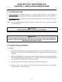
Dean Millivolt Gas Fryers (CE)
Installation & Operation Manual
Models SM20, SM35, SM40, SM50, SM60, SM80, SR42, SR52 & SR62
CE ONLY
Service Hotline 1-318-865-1711
Price: $8.00
819-5894
MAY 2007
Please read all sections of this manual and retain for future reference.
NOTICE
This appliance is intended for professional use only and is to be operated by qualified
personnel only. A Dean Factory Authorized Service Center (FASC) or other qualified
professional should perform installation, maintenance, and repairs. Installation, maintenance,
or repairs by unqualified personnel may void the manufacturer’s warranty. See Chapter 1 of
this manual for definitions of qualified personnel.
NOTICE
This equipment must be installed in accordance with the appropriate national and local codes of
the country and/or region in which the appliance is installed.
NOTICE
Drawings and photos used in this manual are intended to illustrate operational, cleaning and
technical procedures and may not conform to onsite management operational procedures.
NOTICE TO OWNERS OF UNITS EQUIPPED WITH COMPUTERS
U.S.
This device complies with Part 15 of the FCC rules. Operation is subject to the following two
conditions: 1) This device may not cause harmful interference, and 2) This device must accept
any interference received, including interference that may cause undesired operation. While
this device is a verified Class A device, it has been shown to meet Class B limits.
Canada
This digital apparatus does not exceed the Class A or B limits for radio noise emissions as set
out by the ICES-003 standard of the Canadian Department of Communications.
Cet appareil numerique n’emet pas de bruits radioelectriques depassany les limites de classe A
et B prescrites dans la norme NMB-003 edictee par le Ministre des Communications du Canada.
DANGER
Improper installation, adjustment, maintenance or service, and unauthorized alterations or
modifications can cause property damage, injury, or death. Read the installation, operating and
service instructions thoroughly before installing or servicing this equipment. Only qualified
service personnel may convert this appliance to use a gas other than that for which it was
originally configured. See Chapter 1 of this manual for definition of qualified service personnel.
DANGER
Adequate means must be provided to limit the movement of this appliance without depending
upon the gas line connection. Single fryers equipped with legs must be stabilized by installing
anchor straps. All fryers equipped with casters must be stabilized by installing restraining
chains. If a flexible gas line is used, an additional restraining cable must be connected at all
times when the fryer is in use.
i
DANGER
The front ledge of the fryer is not a step. Do not stand on the fryer. Serious injury can result
from slips or contact with the hot oil.
CAUTION
Do not store or use gasoline or other flammable vapors and liquids in the vicinity of this or any
other appliance.
CAUTION
Instructions to be followed in the event the operator smells gas or otherwise detects a gas leak
must be posted in a prominent location. This information can be obtained from the local gas
company or gas supplier.
DANGER
The crumb tray in fryers equipped with a filter system must be emptied into a fireproof container
at the end of frying operations each day. Some food particles can spontaneously combust if left
soaking in certain shortening material. Additional information can be obtained in the filtration
manual included with the system.
WARNING
No structural material on the fryer should be altered or removed to accommodate placement of
the fryer under a hood. Questions? Call the Dean Service Hotline at 1-800-551-8633.
WARNING
Do not bang fry baskets or other utensils on the fryer’s joiner strip. The strip is present to seal
the joint between the frypot. Banging fry baskets on the strip to dislodge shortening will distort
the strip, adversely affecting its fit. It is designed for a tight fit and should only be removed for
cleaning.
IMPORTANT
Safe and satisfactory operation of Dean equipment depends upon its proper installation.
Installation MUST conform with local codes, or in the absence of local codes, to European
Community (CE) Standards.
NOTICE
The Commonwealth of Massachusetts requires any and all gas products to be installed by a
licensed plumber or pipe fitter.
ii
Dean Millivolt Gas Fryers (CE)
Installation & Operation Manual
TABLE OF CONTENTS
Page #
1.
INTRODUCTION
1-1
1.1
Applicability and Validity
1-1
1.2
Ordering Parts
1-1
1.3
Service Information
1-1
1.4
Safety Information
1-2
1.5
Service Personnel
1-2
2.
IMPORTANT INFORMATION
2-1
2.1
Receiving and Unpacking Equipment
2-1
2.2
General
2-1
2.3
Principles of Operation
2-2
2.4
Rating Plate
2-3
2.5
Pre-Installation
2-3
2.6
Equipment Installed at High Altitudes
2-4
2.7
Air Supply and Ventilation
2-4
2.8
Conversion of Units
2-5
3.
INSTALLATION
3-1
3.1
Installing the Fryer
3-1
3.2
Installing Casters and Legs
3-1
3.3
Leveling the Fryer
3-2
3.4
Gas Connections
3-4
3.5
Adjustments/Adaptation to Different Gases
3-8
3.6
Gas Inputs
3-9
3.7
Gas Conversion Procedures
3-11
3.8
Gas Conversion Components
3-13
3.9
Electrical Connections
3-13
i
Dean Millivolt Gas Fryers (CE)
Installation & Operation Manual
TABLE OF CONTENTS (CONT.)
Page #
4.
FRYER OPERATIONS
4-1
4.1
Initial Start-up
4-1
4.2
Boil-Out Procedure
4-3
4.3
Final Preparation
4-5
5........ PREVENTATIVE MAINTENANCE
5-1
5.1
5-1
General
6........ TROUBLESHOOTING
6-1
6.1
General
6-1
6.2
Pilot Burner Malfunctions
6-1
6.3
Main Burner Malfunction
6-2
6.4
Millivolt Wiring Diagram
6-3
6.5
Recommended Spare Parts
6-4
ii
DEAN MILLIVOLT GAS FRYERS (CE)
CHAPTER 1: INTRODUCTION
1.1 Applicability and Validity
Dean Super Marathon and Super Runner Series gas model families have been approved by the
European Union (EU) for sale and installation in the following EU countries: AT, BE, KE, KD,
ES, FI, FR, GB, IE, IT, LU, NL, NO, PT and SE.
This manual is applicable to and valid for all Dean Super Marathon and Super Runner gas
units sold in English-speaking countries, including those in the European Union. Where
conflicts exist between instructions and information in this manual and local or national codes
of the country in which the equipment is installed, installation and operation shall comply with
those codes.
This appliance is only for professional use and shall be used by qualified personnel as defined
in Section 1.5.
1.2 Ordering Parts
Customers may order parts directly from their local Authorized Parts Distributor. For this address
and phone number, contact your maintenance and repair center or call the factory. The factory
address and phone numbers are on the back cover of this manual.
To speed up your order, the following information is required:
Model Number
Serial Number
Optional Equipment
Item Part Number
Type
Quantity Needed
1.3 Service Information
Call the 1-800-551-8633 or (318) 865-1711 Service Hotline number for the location of your nearest
maintenance and repair center. Always give the model and serial numbers of your fryer.
To assist you more efficiently, the following information will be needed:
Model Number
Serial Number
Optional
Equipment
Nature of Problem
Type
Additional information (i.e. cooking environment, time of day, and other pertinent
information) may be helpful in solving your service problem.
1-1
DEAN MILLIVOLT GAS FRYERS (CE)
CHAPTER 1: INTRODUCTION
1.4 Safety Information
Before attempting to operate your unit, read the instructions in this manual thoroughly.
Throughout this manual, you will find notations enclosed in double-bordered boxes similar to the
ones below.
CAUTION boxes contain information about actions or conditions that may cause or result in a
malfunction of your system.
CAUTION
Example of a CAUTION box.
WARNING boxes contain information about actions or conditions that may cause or result in
damage to your system, and which may cause your system to malfunction.
WARNING
Example of a WARNING box.
DANGER boxes contain information about actions or conditions that may cause or result in injury
to personnel, and which may cause damage to your system and/or cause your system to malfunction.
DANGER
Hot cooking oil causes severe burns. Never attempt to move a fryer containing hot
cooking oil or to transfer hot cooking oil from one container to another.
1.5 Service Personnel
1.5.1 Definitions
A. Qualified and/or Authorized Operating Personnel
1.
Qualified/authorized operating personnel are those who have carefully read the information
in this manual and have familiarized themselves with the equipment functions, or have had
previous experience with the operation of equipment covered in this manual.
1-2
DEAN MILLIVOLT GAS FRYERS (CE)
CHAPTER 1: INTRODUCTION
1.5.1 Definitions (cont.)
B. Qualified Installation Personnel
1.
Qualified/authorized personnel are those who have carefully read the information in this
manual and have familiarized themselves with the equipment functions, or who have had
previous experience with the operation of the equipment covered in this manual.
C. Qualified Service Personnel
1.
Qualified service personnel are those who are familiar with Dean equipment and have been
authorized by Dean to perform service on Dean equipment. All authorized service
personnel are required to be equipped with a complete set of service parts manuals and stock
a minimum amount of parts for Dean equipment. A list of Dean Factory Authorized Service
Centers (FASCs) was included with the fryer when shipped from the factory. Failure to use
qualified service personnel will void the Dean warranty on your equipment.
1-3
DEAN MILLIVOLT GAS FRYERS (CE)
CHAPTER 2: IMPORTANT INFORMATION
2.1 Receiving and Unpacking Equipment
A. Check that the container is upright. Use an outward prying motion - no hammering - to remove
the carton. Unpack the fryer carefully and remove all accessories from the carton. Do not discard
or misplace accessories. They will be needed.
B. After unpacking, immediately check the equipment for visible signs of shipping damage. If
damage has occurred, contact the carrier and file the appropriate freight claims. Do not contact
the factory. Shipping damage responsibility is between the carrier and the dealer.
If your equipment arrives damaged:
1.
File claim for damages immediately, regardless of extent of damage.
2.
Visible loss or damage: Be sure this is noted on the freight bill or express receipt and is
signed by the person making the delivery.
3.
Concealed loss or damage: If damage is unnoticed until equipment is unpacked, notify
freight company or carrier immediately, and file a concealed damage claim. The claim
should be filed within 15 days of date of delivery. Be sure to retain container for inspection.
NOTE: Dean Does Not Assume Responsibility for Damage or Loss Incurred in Transit.
C. Move the fryer to the location of installation and install legs and/or casters as described in
Chapter 3.2.
D. Remove all plastic skin from sides, front, and doors of the fryer(s). Failure to do this prior to
initial fryer operation will make it very difficult to remove later.
2.2 General
Qualified, licensed, and/or authorized installation or service personnel only (as defined in
Section 1.5) should perform the following:
•
Installation and service on Dean equipment.
•
Conversion of this appliance from one gas type to another.
Failure to use qualified, licensed, and/or authorized installation or service personnel to install,
convert to another gas type or otherwise service this equipment will void the Dean warranty
and may result in damage to the equipment or injury to personnel.
2-1
DEAN MILLIVOLT GAS FRYERS (CE)
CHAPTER 2: IMPORTANT INFORMATION
2.2 General (cont.)
Where conflicts exist between instructions and information in this manual and local code or
national codes, or regulations, installation and operation shall comply with the codes or
regulations in force in the country in which the equipment is installed.
DANGER
Building codes prohibit a fryer with its open tank of hot oil/shortening from being installed
beside an open flame of any type, including those of broilers and ranges.
Upon arrival, inspect the fryer carefully for visible or concealed damage. (See Receiving and
Unpacking Equipment in Section 2.7.)
CAUTION
Dean appliances equipped with legs are for stationary installations. Appliances fitted with
legs must be lifted during movement to avoid damage to the appliance and bodily injury.
For moveable installations, optional equipment casters must be used. Questions? Call 1800-551-8633
Dean Super Marathon and Super Runner Series gas fryers are energy efficient, tube-style, gas-fired
units. All units are shipped completely assembled with accessories packed inside the frypot. All
units are adjusted, tested and inspected at the factory before shipment. Sizes and input rates of all
models are listed in this manual.
WARNING
The on-site supervisor is responsible for ensuring that operators are made aware of
the inherent dangers of operating a hot-oil fryer/filter system, particularly the
aspects of fryer operation, oil filtration, and draining/cleaning procedures.
2.3 Principles of Operation
The incoming gas flows through orifices and is mixed with air in the burners to create the correct
ratio for proper combustion. The mixture is ignited at the front end of each heat tube by the pilot
light. Internal diffusers slow the flame as it goes through the burner tube. This slower and more
turbulent flame gives much better heat transfer to the walls of the tubes, thereby heating the oil more
efficiently.
2-2
DEAN MILLIVOLT GAS FRYERS (CE)
CHAPTER 2: IMPORTANT INFORMATION
2.4 Rating Plate
DANGER
Fryers MUST be connected ONLY to the gas-type identified on the attached rating
plate.
The rating plate can be found on the inside panel of the fryer door. Information on this plate
includes the model and serial numbers, kW/hr (BTU/hr) of the burners, outlet gas pressure in mbars
(inches W.C.), and configuration: natural or propane gas. Rating plate data is essential for proper
unit identification, communicating with the factory or requesting special parts and/or information.
2.5 Pre-Installation
DANGER
No structural material on the fryer should be altered or removed to accommodate
placement of the fryer under a hood. Questions? Call the Frymaster/Dean Service
Hotline at 1-800-551-8633.
DANGER
Do not connect this appliance to the gas supply before reviewing all information in
this chapter.
A. General: Only licensed personnel should install any gas-fired equipment.
1.
A manual gas shut-off valve must be installed in the gas supply line ahead of the fryers for
safety and ease of future service.
2.
Dean Super Marathon and Super Runner Series gas fryers operate on millivolt, and do not
require an external electric power supply.
B. Clearances: The fryer area must be kept free and clear of all combustibles. This unit is design-
certified for the following installations:
1.
Commercial installation only (not for household use).
2.
Non-combustible floor installation equipped with factory-supplied 6-inch (15-cm) adjustable
legs or 5-inch (13-cm) casters;
3.
Combustible construction with a minimum clearance of 6-inches (15-cm) side and 6-inches
(15-cm) rear, and equipped with factory-supplied 6-inch (15-cm) adjustable legs or 5-inch
(13-cm) casters.
2-3
DEAN MILLIVOLT GAS FRYERS (CE)
CHAPTER 2: IMPORTANT INFORMATION
2.5 Pre-Installation (cont.)
C. Installation Standards
1.
CE/EXPORT STANDARDS: Fryer installation must conform with local codes, or in the
absence of local codes, to the appropriate national or European Community (CE) standards.
2.6 Equipment Installed at High Altitudes
A. The fryer input rating (kW/hr) is for elevations up to 2,000 feet (610-m). For elevations above
2,000 feet (610-m), the rating should be reduced four-percent for each additional 1,000 feet (305m) above sea level.
B. The correct orifices are installed at the factory if the operating altitude is known at the time of the
customer’s order.
2.7 Air Supply and Ventilation
Keep the area around the fryer clear to prevent obstruction of combustion and ventilation airflow.
A. Do not connect this fryer to an exhaust duct.
B. Correct installation and adjustment will ensure adequate airflow to the fryer system.
C. A commercial, heavy-duty fryer must vent its combustion wastes to the outside of the building.
A deep-fat fryer must be installed under a powered exhaust hood, or an exhaust fan must be
provided in the wall above the unit, as exhaust gas temperatures are approximately 427-538°C
(800-1000°F). Check air movement during installation. Strong exhaust fans in the exhaust hood
or in the overall air conditioning system can produce slight air drafts in the room.
D. Do not place the fryer’s flue outlet directly into the plenum of the hood, as it will affect the gas
combustion of the fryer.
E. Never use the interior of the fryer cabinet for storage or store items on shelving over or behind
the fryer. Exhaust temperatures can exceed 427ºC (800°F) and may damage or melt items stored
in or near the fryer.
F. Adequate distance must be maintained from the flue outlet of the fryer(s) to the lower edge of the
filter bank. Per NFPA Standards No. 96, a minimum of 18-inches (45-cm) should be maintained
between the flue(s) and the lower edge of the exhaust hood filter.
G. Filters and drip troughs should be part of any industrial hood, but consult local codes before
constructing and installing any hood. The duct system, the exhaust hood and the filter bank must
be cleaned on a regular basis and kept free of grease.
2-4
DEAN MILLIVOLT GAS FRYERS (CE)
CHAPTER 2: IMPORTANT INFORMATION
2.8 Conversion of Units
Pressure:
1 mbar = 10,2 mm W.C. = 0,4-inch W.C.
20 mbar = 204 mm W.C. = 8-inch W.C.
1-inch W.C. = 25,4 mm W.C. = 2,5 mbar
Heat Input:
1 kW = 3410 BTU/hr
100 BTU/hr = 0,0293 kW
Temperature:
0° Celsius = 32° Fahrenheit
Temperature in degrees Celsius = (Temperature in degrees Fahrenheit (F) – 32) x 0,555
100° Celsius = (212° Fahrenheit – 32) x 0,555
2-5
DEAN MILLIVOLT GAS FRYERS (CE)
CHAPTER 3: INSTALLATION INSTRUCTIONS
3.1 Installing the Fryer
A. Initial Installation: If installed with legs, do not push against the fryer’s side to adjust its
position. Use a pallet or lift jack to lift the fryer slightly and place it where it is to be installed.
B. Relocating the Fryer: If relocating a fryer installed with legs, remove all weight from each leg
before moving.
Note:
If a leg becomes damaged during movement, contact your service agent for immediate
repair/replacement.
CAUTION
Fryers may not function properly if curb mounted.
DANGER
This fryer may tip and cause personal injury if not secured correctly in a stationary
position. Drain all oil/shortening from fryer before moving. Hot oil will splash and
cause severe burns upon contact.
3.2 Leg and Caster Installation
A. General
1.
Install legs and rear rigid casters near where the fryer is to be used, as neither are secure for
long transit. Unit cannot be curb mounted and must be equipped with the legs and casters
provided.
2.
When positioning the fryer, gently lower the fryer into position to prevent undue strain to
the legs and internal mounting hardware. Use a pallet or lift jack to lift and position the
fryer if possible. Tilting the fryer may damage the legs.
3.
The rigid casters must be installed on the fryer rear channel assembly only.
4.
Proceed to Step 3.3, Leveling the Fryer, after legs and rear rigid casters are installed to
ensure the fryer is level before using.
3-1
DEAN MILLIVOLT GAS FRYERS (CE)
CHAPTER 3: INSTALLATION INSTRUCTIONS
3.2 Leg and Caster Installation (cont.)
B. Leg and Rigid Caster Installation
1. Remove unit from pallet.
2. Carefully raise unit with forklift, pallet jack, or other steady means.
3. Place one lock washer on each hex head screw.
4.
Insert hex head screws with lock washers [1/4-20 threads by 19 mm (¾") long] through bolt
holes of leg mounting plates and mount to the front channel. Mount rigid casters to the rear
channel following the same procedure. A locknut has been attached to the topside of the
base mounting plates at the factory to capture the hex head screw as it is screwed in.
5.
Tighten the bolts to 5.65 Nm (50 inch-lbs.) torque.
CAUTION
For caster retrofit, the unit must be at room temperature and drained of shortening
before installing the casters.
3.3 Leveling the Fryer
A. Place a carpenter’s spirit level across the top of the fryer and level the unit front to back. If the
fryer is off level side to side, a platform or other surface adjustment is needed; there is no sideto-side level adjustments on a fryer equipped with caster/leg combinations. (If a fryer is
equipped with legs only, side-to-side level adjustments can be made. If a fryer is equipped with
casters only, no level adjustments to the fryer can be made.). If the fryer is not level, the unit
may not function efficiently, the oil may not drain properly for filtering and in a multi-fryer
battery, it may not match adjacent units.
Legs (Only)
1.
Adjust leg height with an adjustable or 27 mm (1-1/16-inch) open-end wrench by turning
the hex bullet on the bottom of the leg.
2.
The hex bullet is for minor leg height adjustment only. Do not adjust more than 22 mm.
3.
When leveling the unit, the leg body should be held firmly to keep the leg from bending or
rotating while turning the hex bullet foot to the required height.
3-2
DEAN MILLIVOLT GAS FRYERS (CE)
CHAPTER 3: INSTALLATION INSTRUCTIONS
3.3 Leveling the Fryer (cont.)
Rigid Casters (Only)
1.
Install the rigid casters on the fryer rear channel only. Legs must be installed on the front
channel.
2. There are no level adjustments for the rigid casters.
B. If the floor is uneven or has a decided slope, place the fryer on a smooth, level platform.
C. If the fryer is moved, re-level the fryer following the instructions given in Steps 3.3.A-C.
D. An installed fryer must be restrained to prevent tipping, which could splash hot oil. Restraints
can be straps or chains anchored to an immovable object (wall, floor anchor), or be the manner
of installation (installing the fryer in an alcove, battering to other appliances, etc.).
E. Installing Optional Swivel Casters:
1.
Install non-locking casters only at the rear of the unit.
2.
Locking casters must be installed at the front of the unit. Locking casters allow the fryer to
be "locked" in position for safe operations.
3.
Follow the same instructions for leg installations as given above in steps 3.2, B1-5.
Front View
Rear Side View
Optional CasterRear Only
Optional CasterFront Only
Rear Caster—5" Rigid
Front Caster—5" Swivel
w/Brake
1/4-20 x 3/4 Hex Bolt
Front Channel or
Rear Channel
Front Channel
or Rear Channel
Leg Support Assembly
Washer
1/4-20 Hex Head Locknut
Front or Rear Leg with
Mounting Plate
1/4-20 x 3/4 Hex Bolt
Adjust as needed
Leg and Caster (Optional) Mounting Installation
3-3
DEAN MILLIVOLT GAS FRYERS (CE)
CHAPTER 3: INSTALLATION INSTRUCTIONS
3.3 Leveling the Fryer (cont.)
NOTE: The installation must be inspected after it is complete to ensure it meets the intent of
these instructions. The on-site supervisor and/or operator(s) should be informed that the
appliance is installed with restraints. If restraints are removed to move fryer (cleaning
beneath and behind, relocation, etc.), ensure that they are re-installed when fryer is returned
to its permanently installed position.
CAUTION
The fryer MUST be connected to the gas supply specified on the rating and serial number
plate located on the back of the fryer door.
WARNING
If gas odors are detected, the gas supply MUST be shut off at the main shut-off valve. The
local gas company or FASC should be contacted immediately to rectify the problem.
3.4 Gas Connections
Dean Super Marathon and Super Runner Series gas fryers have obtained CE markings for countries
and gas categories shown below:
Supply Pressures and Gas
Appliance Categories
(mbar)
Countries
BE
DE
DK
ES
FR
GB
GR
IR
IT
LU
NL
PT
G20
G31
G20
Germany
G31
Denmark
G20
G20
Spain
G31
G20/G25
France
G31
G20
Great Britain
G31
G20
Greece
G31
G20
Ireland
G31
Italy
G20
G20/G25
Luxembourg
G31
G25
The Netherlands
G31
G20
Portugal
G31
20/25
37
20
50
20
20
37 and 50
20/25
37 and 50
20
37
20
37 and 50
20
37
20
20/25
50
25
50
20
37
Belgium
3-4
IIE(R)B3P
I2E
I3P
I2H
II2H3P
II2ESI3P
II2H3P
II2H3P
II2H3P
I2H
II2E3P
II2L3P
II2H3P
DEAN MILLIVOLT GAS FRYERS (CE)
CHAPTER 3: INSTALLATION INSTRUCTIONS
3.4 Gas Connections (cont.)
NATIONAL CODE REQUIREMENTS
This equipment is to be installed in compliance with the Basic Plumbing Code of the Building
Officials and Code Administrators International, Inc. (BOCA) and the Food Service Sanitation
Manual of the U.S. Food and Drug Administration.
This equipment is manufactured to use the type of gas specified on the rating plate attached to the
door. Connect equipment stamped "NAT" only to natural gas and that stamped "PRO" only to LP
(Propane) gas.
DANGER
Before connecting new pipe to this appliance the pipe must be blown out thoroughly
to remove all foreign material. Foreign material in the burner and gas controls will
cause improper and dangerous operation.
The gas supply (service) line must be the same size or greater than the fryer inlet line. Dean Super
Marathon and Super Runner gas fryers are equipped with 22 mm male ISO 7.1 inlet. The gas supply
line must be sized to accommodate all gas-fired equipment connected to that gas supply. Consult
local gas companies or suppliers, or your local contractor for minimum supply line requirements.
Supply Line Specifications
The gas supply lines must be sized as indicated in the chart below, based on the total number of
fryers connected to the main gas supply.
Recommended Gas Supply Line Sizes
Number of Fryers
1
2 to 3
4 or more (*)
Natural Gas
22 mm
28 mm
35 mm
Propane Gas
15 mm
22 mm
28 mm
(*) When exceeding 6 meters for a configuration of more than four fryers, it is necessary to
provide a 33 mm rigid gas connection.
Gas Types
DANGER
All connections must be sealed with a joint compound suitable for the gas being
used and all connections must be tested with a solution of soapy water before
lighting any pilots.
Never use matches, candles, or any other ignition source to check for leaks. If gas
odors are detected, shut off the gas supply to the appliance at the main shut-off
valve and immediately contact the local gas company or an authorized service
agency for service.
3-5
DEAN MILLIVOLT GAS FRYERS (CE)
CHAPTER 3: INSTALLATION INSTRUCTIONS
3.4 Gas Connections (cont.)
DANGER
"Dry-firing" your unit will cause damage to the frypot and can cause a fire. Always
ensure that melted shortening, cooking oil or water is in the frypot before firing the
unit.
Rigid Connections
Check any installer-supplied intake pipe(s) visually and clean metal particles or other foreign matter
from the threads before installing into a service line. If the intake pipes are not clear of all foreign
matter, the orifices will clog when gas pressure is applied. When using thread compound on gas
piping, use very small amounts and only on male threads. Use a pipe thread compound that is not
affected by the chemical action of LP gases. DO NOT apply thread compound to the first two pipe
threads – doing so will cause clogging of the burner orifices and control valve.
Manual shut-off valve
This gas service supplier-installed valve must be installed in the gas service line ahead of the fryers
in the gas stream and in a position where it can be reached quickly in the event of an emergency.
Regulating Gas Pressure
The fryer and shut-off valve must be disconnected from the gas supply during any pressure testing of
the system.
External gas regulators are not normally required on this fryer. A safety control valve protects the
fryer against pressure fluctuations. If the incoming pressure is in excess of 3.45 kPa/35 mbar, a
step-down regulator will be required.
DANGER
When pressure-testing incoming gas supply lines, disconnect the fryer from the gas
line if the test pressure is 3,45 kPa (½" PSI, 13,84 inches W.C.) or greater to avoid
damage to the fryer’s gas piping and gas valve(s).
A. Manifold Pressure: Your local service technician should check the manifold pressure with a
manometer.
1.
Check the rating plate for manifold gas pressures. Natural gas units normally require 10
mbar, and propane units normally require 27 mbar gas pressure.
2.
Confirm that the arrow forged into the bottom of the regulator body, which indicates gas
flow direction, is pointed downstream towards the fryers. The air vent cap is also part
of the regulator and should not be removed.
3-6
DEAN MILLIVOLT GAS FRYERS (CE)
CHAPTER 3: INSTALLATION INSTRUCTIONS
3.4 Gas Connections (cont.)
3.
If a vent line from the gas pressure regulator is used, it should be installed in accordance
with local codes or in the absence of local codes, with the appropriate national or
European Community (CE) standards.
WARNING
Use a diluted soap solution to find potentially dangerous gas leaks when making
new connections.
B. Regulators: Gas regulators can be adjusted in the field, but no adjustments should be made
unless the regulator is out of adjustment, or serious pressure fluctuations are observed.
C. Only qualified service personnel should make adjustments to the regulators.
D. Orifices: The fryer can be configured to operate on any available gas. The correct safety
control valve, appropriate gas orifices, and pilot burner are installed at the factory. While
the valve can be adjusted in the field, only qualified service personnel should make any
adjustments with the proper test equipment.
1. The following color codes indicate the type of gas to be used for each fryer and
associated components.
Gas Type
Natural
Propane
CE Color Code
Blue
Red
E. Flexible Couplings, Connectors and Casters
1. If the fryer is to be installed with flexible couplings and/or quick-disconnect fittings, the
installer must use a heavy-duty certified commercial flexible connector of at least 22 mm
NPT (with suitable strain-relief attachments), in compliance with local codes or in the
absence of local codes, with the appropriate national or European Community (CE)
standards. Quick-disconnect devices must comply with local codes or in the absence of
local codes, with the appropriate national or European Community (CE) standards.
2. For an appliance equipped with casters, the installation shall be made with a connector
that complies with local codes or in the absence of local codes, with the appropriate
national or European Community (CE) standards.
3. Under no circumstances are the connector and the quick-disconnect device, or its
associated piping to be used to limit fryer movement. A restraining bracket is provided on
the appliance back to prevent the unit from moving from its installed position.
3-7
DEAN MILLIVOLT GAS FRYERS (CE)
CHAPTER 3: INSTALLATION INSTRUCTIONS
3.4 Gas Connections (cont.)
WARNING
Do not attach accessories to this fryer unless fryer is secured from tipping.
Personal injury may result.
4. To limit movement of the fryer, restraints independent of the flexible coupling or
connector must be used. Clips are located on the back panel of the fryer for the
attachment of restraints.
5. If disconnection of the restraint is necessary, the restraint must be reconnected after the
fryer has been returned to its originally installed position.
F. After hook up, bleed the gas line of air to ensure that the pilot light will ignite quickly and
evenly.
CAUTION
Qualified personnel MUST perform any adaptation, modification, or gas conversion,
if required. Failure to use qualified personnel will void the Dean warranty.
3.5 Adjustments/Adaptation To Different Gases
WARNING
Qualified personnel MUST perform any adaptation, modification, or gas conversion,
if required. Failure to use qualified personnel will void the Dean warranty.
A. Proper operation of appliances requires operator to inspect the following adjustments in
Section 3.6 in terms of gas inputs and pressures.
B. Dean Super Marathon and Super Runner Series gas fryers are manufactured to use the type
of gas and pressure specified on the rating plate. When changing gas, adaptation must be
performed by qualified personnel. Failure to use qualified personnel will void the Dean
warranty.
3-8
DEAN MILLIVOLT GAS FRYERS (CE)
CHAPTER 3: INSTALLATION INSTRUCTIONS
3.6 Gas Inputs
Nominal Heat Inputs (Qn), Gas Type, Orifice Size, Part Number and Quantity/Color are listed in the
table below:
MODEL
NOMINAL HEAT
INPUT- Qn
(kW)
GAS
TYPE
ORIFICE SIZE
(MM)
ORIFICE
PART NO.
ORIFICE
QTY/ COLOR
SM 80 GM
37.5
G20
G25
G31
2.40
2.40
1.51
810-2060
810-2060
810-2059
5/BLUE
5/BLUE
5/RED
SM 60 GM
37.5
G20
G25
G31
2.40
2.40
1.51
810-2060
810-2060
810-2059
5/BLUE
5/BLUE
5/RED
SR 52 GM
SM 50 GM
30
G20
G25
G31
2.40
2.40
1.51
810-2060
810-2060
810-2059
4/BLUE
4/BLUE
4/RED
SM 35 GM
SR 38G
SR 42G
26
G20
G25
G31
2.40
2.40
1.51
810-2060/*810-3101
810-2060/*810-3101
810-2059/*810-3102
3/BLUE
3/BLUE
3/RED
SM 20 GM
15
G20
G25
G31
2.40
2.40
1.51
810-2060
810-2060
810-2059
2/BLUE
2/BLUE
2/RED
*Use these orifices on SR42 fryers built after 4/07.
A. Adjustments for different gases are as follows:
ORIFICE
SIZE (MM)
GAS TYPE
SM 80GM
2,40
2,40
1,51
2,40(1)
SM 60GM
2,40
2,40
1,51
MODEL*
GAS PRESSURE AT
REGULATOR
BURNER
MARKING
PILOT
MARKING
MBAR
INCH W.C.
G20
G25
G31
G25(1)
10,0
15,0
27,0
10,0(1)
4,0
6,0
10,8
4,0(1)
Blue
Blue
Red
Blue
26N
26N
16LP
26N
G20
G25
G31
12,0
17,5
22,0
4,8
7,0
8,8
Blue
Blue
Red
26N
26N
16LP
*SR prefix- Super Runner Series
*SM prefix- Super Marathon Series
*GM suffix- gas millivolt system with no electrical supply connections required
(1) The Netherlands (NL) only.
3-9
DEAN MILLIVOLT GAS FRYERS (CE)
CHAPTER 3: INSTALLATION INSTRUCTIONS
3.6 Gas Inputs (cont.)
A. Adjustments for different gases are as follows (cont.):
GAS PRESSURE AT
REGULATOR
BURNER
MARKING
PILOT
MARKING
4,8
7,0
8,8
Blue
Blue
Red
26N
26N
16LP
12,0
17,5
22,0
4,8
7,0
8,8
Blue
Blue
Red
12,0
17,5
22,0
4,8
7,0
8,8
Blue
Blue
Red
MODEL*
ORIFICE
SIZE (MM)
GAS TYPE
SR 52GM
SM 50GM
2,40
2,40
1,51
G20
G25
G31
12,0
17,5
22,0
SM 35GM
SR 38GM
SR 42GM
2,40
2,40
1,51
G20
G25
G31
SM 20GM
2,40
2,40
1,51
G20
G25
G31
26N
26N
16LP
26N
26N
16LP
*SR prefix- Super Runner Series
*SM prefix- Super Marathon Series
*GM suffix- gas millivolt system with no electrical supply connections required
(1) The Netherlands (NL) only.
NOTE: Outlet gas pressure must be adjusted strictly within the above requirements 5 to 10 minutes
after the appliance is operating.
* For controls and adjustments, please refer to the gas valve illustration on page 3-12. (Pilot Flame
Adjustment: Turn the pilot adjustment screw clockwise/counter-clockwise until the desired flamevolume is achieved).
WARNING
If gas odors are detected, the gas supply MUST be shut off at the main shut-off
valve, and the local gas company or authorized service agency contacted for
immediate service.
3-10
DEAN MILLIVOLT GAS FRYERS (CE)
CHAPTER 3: INSTALLATION INSTRUCTIONS
3.7 Gas Conversion Procedures
DANGER
This appliance was configured at the factory for a specific type of gas. Converting
from one gas type to another requires the installation of specific gas-conversion
components.
Switching to a different type of gas without installing the proper conversion
components may result in fire or explosion. NEVER ATTACH THIS APPLIANCE TO A
GAS SUPPLY FOR WHICH IT IS NOT CONFIGURED!
Conversion of this appliance from one type of gas to another should only be
performed by qualified, licensed, and authorized installation or service personnel, as
defined in Section 1.5 of this manual.
See page 3-12 for gas valve illustration and gas valve, burner and orifice location when performing
the following conversions.
When converting from G20 to G25 gas, the following procedures apply:
♦
♦
♦
Equipment replacement is not required.
Adjust orifice gas pressure to the appropriate value listed in the table on page 3-9 – 3-10 by
turning the gas valve "adjustment screw".
After adjustment, replace the adjustment-screw cover.
When converting from G20 (or G25) gas to G31 propane (or vice-versa), the following procedures
apply:
♦
♦
♦
♦
Burner orifices and pilot orifice MUST be replaced.
Adjust orifice gas pressure to the appropriate value listed in the table on page 3-9 – 3-10 by
turning the gas-valve adjustment screw.
After adjustment, replace the adjustment-screw cover.
Affix the new label included with the conversion kit next to the existing rating plate stating
that the gas type has been converted. Remove any references to the previously used gas
from the existing rating plate.
When converting from G20 (20 mbar) to G25 (25 mbar), or vice-versa, or G31 (37 mbar) to G31 (50
mbar), the following procedures apply:
♦
♦
Check pilot-adjustment and adjust as necessary.
Other adjustments are not necessary.
Conversion from one gas family to another (i.e. changing from natural gas to propane) requires
special components. Obtain the necessary components using the cross-reference in Section 3.8, Gas
Conversion Components.
3-11
DEAN MILLIVOLT GAS FRYERS (CE)
CHAPTER 3: INSTALLATION INSTRUCTIONS
3.7 Gas Conversion Procedures (cont.)
Conversions can only be executed by qualified, factory-authorized personnel.
ON Button(pilot gas flow)
OFF Button
Vent tube
connection
CE Gas
Valve
Pressure flow
adjustment
Pilot flow
adjustment
Thermocouple
connection
Vessel Assembly
1/2—3/4 Reducer
Bushing
Manifold Support Bracket
Gas Valve
Gas Burner
Burner
See Detail A
1.63-inch [41-mm]
Orifice
1.30-inch [33-mm]
Pressure
Test
Spigot
Gas Manifold
Orifice
Gas
Manifold
Assembly
Detail A
Burner/Orifice Location
Temperature
Control
Typical gas valve, burner and orifice locations (SM35/SR42 shown above).
3-12
DEAN MILLIVOLT GAS FRYERS (CE)
CHAPTER 3: INSTALLATION INSTRUCTIONS
3.8 Gas Conversion Components
Use the following components to convert from natural gas to propane and vice-versa. See Section
3.6 for orifice quantities required for conversion. NOTE: On SR42 units built after 4/07, use Kit
826-1817 to convert from natural to propane. Use kit 826-2017 to convert from propane to natural.
The kits include bushings to accommodate the smaller orifice port on the newer fryers.
Natural Gas to Propane Components
Propane To Natural Gas Components
REF
DESCRIPTION
REF
DESCRIPTION
810-2400
Pilot orifice (LP)
810-0811
Pilot orifice (26N)
810-2059
Burner orifice
(diameter: 1.51 mm)†
810-2060
Burner orifice
(diameter: 2.40 mm)†
New Rating Contact factory at time of New Rating Contact factory at time of
Label
Label
conversion. PN 802-2144
conversion. PN 802-2144
†Burner orifices listed are for fryers operating at altitudes of 610 meters or less. For
altitudes greater than 610 meters, contact the factory for the correct orifice size.
3.9 Electrical Connections
Fryers without built-in filtration do not require electrical connection. Fryer systems with built-in
filtration when installed must be electrically grounded in accordance with local codes, or in the
absence of local codes, with the appropriate national standards.
WARNING
Fryers with built-in filtration systems are equipped with a three-prong (grounding)
plug for protection against shock hazard. It should be plugged directly into a
properly grounded, three-prong receptacle. DO NOT CUT, REMOVE, OR
OTHERWISE BYPASS THE GROUNDING PRONG ON THIS PLUG.
For fryers with built-in filtration systems: The rating plate and wiring diagram are located on the
inside front door panel. Built-in filtration systems are equipped with 120VAC single-phase 60-hertz
system (Domestic), or 230VAC single-phase 50-hertz system (International/CE). Do not cut or
remove the ground prong from the power cord plug.
DANGER
This appliance requires electrical power (built-in filtration systems only) for
operation. Place the gas control valve in the OFF position in case of a prolonged
power outage. Do not attempt to operate this appliance during a power outage.
3-13
DEAN MILLIVOLT GAS FRYERS (CE)
CHAPTER 4: FRYER OPERATION
4.1 Initial Startup
WARNING
The on-site supervisor is responsible for ensuring that operators are made aware of
the inherent hazards of operating a hot oil frying system, particularly the aspects of
system operation, oil filtration, draining and cleaning procedures.
New units are wiped clean with solvents at the factory to remove any visible signs of dirt, oil, grease,
etc., remaining from the manufacturing process, then coated lightly with oil. Wash thoroughly with
hot, soapy water to remove any film residue and dust or debris before food preparation, then rinse
out and wipe dry. Wash also any accessories shipped with the unit. Close the drain valve completely
and remove the crumb screen. Ensure the screws holding the thermostat and high-limit control
sensing bulbs into the frypot are tight.
Typical high-limit/sensor probe
location and mounting hardware.
Typical frypot drain valve
(SM35/SR42 shown).
WARNING
Do not bang fry baskets or other utensils on the fryer’s joiner strip. The strip is
present to seal the joint between the frypot. Banging fry baskets on the strip to
dislodge shortening will distort the strip, adversely affecting its fit. It is designed for
a tight fit and should only be removed for cleaning.
DANGER
Never operate this appliance with an empty frypot. The frypot must be filled with
water or cooking oil/shortening before lighting the burners. Failure to do so will
damage the frypot and may cause a fire.
4-1
DEAN MILLIVOLT GAS FRYERS (CE)
CHAPTER 4: FRYER OPERATION
4.1.1 Pilot Lighting Procedures
Initial Pilot Lighting: All Dean fryers are tested, adjusted and calibrated to sea level conditions
before leaving the factory. Adjustments to assure proper operation of pilot may be necessary on
installation to meet local conditions, low gas pressure, differences in altitude and variations in gas
characteristics. These adjustments correct possible problems caused by rough handling or vibration
during shipment, and are to be performed only by qualified service personnel. These adjustments
are the responsibility of the customer and/or the dealer and are not covered by the Dean warranty.
The inlet pipe at the lower rear of the fryer brings incoming gas to the pilot safety control valve, then
to the pilot and main burners. The pilot is located high in the cabinet, left-center, at the base of the
frypot.
WARNING
When checking for burner ignition or performance, do not get too close to the
burners. Slow ignition can cause possible flashback, increasing the potential for
facial and body burns.
Ensure that the following steps are done in
sequence before lighting or re-lighting the pilot:
1. Turn off the manual shut-off valve on the
incoming service line.
2. Turn the operating thermostat "OFF".
3. Depress the Pilot Off button (red) on the
safety control valve to turn "OFF".
4. Wait at least 5 minutes for any accumulated
gas to disperse.
5. Fill the frypot with oil or water to the bottom
OIL LEVEL line scribed on the frypot back.
Ensure heating tubes are covered in liquid
prior to engaging burners.
Honeywell gas valve.
6. Open the manual shut-off valve on the incoming service line.
7. Apply a lighted match or taper to the pilot burner head. (If fryer is equipped with a piezo ignitor,
go to Step 8).
8. Press the white pilot light button on the gas valve and hold approximately 45 seconds to 1
minute, until the pilot stays lit. (If fryer is equipped with a piezo ignitor, press and hold the
white pilot light button, then repeatedly press the piezo ignitor button until the pilot lights.
Release the white button after approximately 45 seconds to 1 minute.)
4-2
DEAN MILLIVOLT GAS FRYERS (CE)
CHAPTER 4: FRYER OPERATION
4.1.1 Pilot Lighting Procedures (cont.)
9. If the pilot does not stay lit, depress the white pilot light button and re-light the pilot, holding the
button in longer before releasing. Trapped air may necessitate re-lighting the pilot several times
until a constant gas flow is attained.
10. When the pilot stays lit, release the white pilot light button.
11. Turn the thermostat to any "ON" setting and ensure the main burner ignites from the pilot.
4.2 Boil-Out Procedure
DANGER
Never leave the fryer unattended during the boil-out process. If the boil-out solution
boils over, turn the fryer off immediately and let the solution cool for a few minutes
before resuming the process.
WARNING
Do not drain boil-out solution into a shortening disposal unit, a built-in filtration unit,
or a portable filter unit. These units are not intended for this purpose, and will be
damaged by the solution.
DANGER
Remove all drops of water from the frypot before filling with cooking oil or
shortening. Failure to do so will cause spattering of hot liquid when the oil or
shortening is heated to cooking temperature and may cause injury to nearby
personnel.
1. Empty frypot and pour in cleaning solution concentrate. Add water to the bottom OIL LEVEL
line scribed in the back of the frypot.
2. Set the operating thermostat-dial/temperature controller to 107°C (225°F), just above that of
boiling water.
3. The main burner will ignite.
4. Reset the temperature controller to 93°C (200°F).
5. The burners should shut off, just as the boil-out solution reaches setpoint.
CAUTION
If the pilot and main burner go out, the fryer(s) MUST be left completely shut down at
least 5 minutes before lighting.
4-3
DEAN MILLIVOLT GAS FRYERS (CE)
CHAPTER 4: FRYER OPERATION
4.2 Boil-Out Procedure (cont.)
6. The burners will heat the boil-out solution to a simmer. Simmer the solution for approximately
45 minutes. Wearing protective gloves, scrub the sides of the frypot and the tubes with the Lshaped Teflon brush (optional on certain models), being careful not to disturb the temperature
sensing probes and the high-limit thermostat.
CAUTION
Do not leave fryer unattended. The boil-out solution may foam and overflow if fryer is
left unattended. If this happens, turn thermostat to "OFF" and gas valve to PILOT.
Resume boil out when foam dissipates.
7. Do not allow the water level to decrease below bottom OIL LEVEL line in frypot during boil-out
operation.
WARNING
Water or boil-out solution MUST not be allowed to drain into the filter pan or filter
system. Irreversible damage will result if water is allowed into the system.
8. After boil out is complete, turn the thermostat-dial/Thermatron controller to "OFF" and drain the
solution from the frypot. Place a metal stockpot of sufficient size to safely hold the entire
contents of the frypot under the drain port to collect the water/boil-out solution. Do not allow
water or boil-out solution to drain into the filter pan. The filter pump is not designed for water
operation, and will be irreparably damaged (see warning statement above).
9. Close the drain, add fresh water (without boil-out solution) and wash all surfaces of the frypot.
Drain again.
10. Refill the frypot with fresh water and vinegar to neutralize any residual boil-out solution. Wash
all surfaces of the frypot. Drain completely and wipe down all surfaces of the frypot to
completely eliminate water from the frypot.
IMPORTANT
Refill frypot with oil or wipe frypot interior with oil immediately to prevent oxidation
and rust from forming.
NOTE: It is recommended that the boil-out procedure be performed each time the oil/shortening
is changed.
WARNING
All drops of water MUST be removed from frypot before filling with cooking oil. Do
not turn fryer on to dry…extensive damage will occur to frypot, and ALL applicable
warranties will be voided.
4-4
DEAN MILLIVOLT GAS FRYERS (CE)
CHAPTER 4: FRYER OPERATION
4.3 Final Preparation
DANGER
Do not go near the area directly over the flue outlet while the fryer is operating.
Always wear oil-proof, insulated gloves when working with the fryer filled with hot
oil.
Always drain hot oil into a metal stockpot of sufficient size to safely hold the entire
contents of the frypot.
WARNING
NEVER set a complete block of solid shortening on top of heating tubes. To do so
will damage the heating tubes and frypot, and void the warranty.
1. When using a liquid shortening (cooking oil), fill the fryer to the bottom OIL LEVEL line
scribed into the back of the frypot.
2. When using a solid shortening, first melt it in a suitable container, or cut it into small pieces and
pack it below the heat tubes, between the tubes and on top of the tubes, leaving no air spaces
around the tubes. Do not disturb or bend the sensing bulbs.
3. Turn the burners "ON" for about 10 seconds, "OFF" for 1 minute, etc., until the shortening is
melted. If you see smoke coming from the shortening while melting this way, shorten the "ON"
cycle and lengthen the "OFF" cycle. Smoke indicates potential scorching of the shortening,
which will shorten its useful life.
4. Before starting operation, turn the operating thermostat to the probable working temperature.
Wait for the oil temperature to stabilize then check with a high-quality immersion thermometer.
4.3.1 Extending Shortening/Oil Life
Although 177°C (350°F) is the recommended temperature for most cooking operations, set the fryer
at the lowest possible temperature which produces a high quality end product. This ensures
maximum life of shortening.
When the fryer is not in use, set the thermostat to a lower temperature than that used during cooking.
Light loads, too, may be cooked at lower temperatures. A good operator should experiment to
determine the optimum temperature and load conditions for the various food items to be cooked.
4-5
DEAN MILLIVOLT GAS FRYERS (CE)
CHAPTER 4: FRYER OPERATION
4.3.2 Opening: Beginning the Work Day
At the beginning of each work day, always check the fryer to ensure:
1.
The combination or main gas valve is "OFF".
2.
Frypot is filled with liquid oil to the lower OIL LEVEL line scribed into the rear wall of the
frypot.
To light the fryer:
1.
Open the manual shut-off valve on the incoming service line.
2.
Light the pilot.
a.
See Section 4.1.1 for pilot lighting procedures.
After the pilot is lit:
1. Release the white pilot button.
2. Turn the thermostat to the desired cooking temperature. Watch to ensure the main burner
ignites from the pilot.
3. Allow the oil/shortening-filled frypot to heat for approximately 30 minutes before cooking.
Oil temperature will stabilize at the desired setpoint, ensuring quality cooking.
4.3.3 Filtering Basics
CAUTION
When filtering, never leave the filter unit unattended. Oil moving through the lines
can knock the flexible return hose out of the fryer, spraying hot oil and causing
severe burns.
DANGER
The crumb tray in fryers equipped with a filter system must be emptied into a
fireproof container at the end of frying operations each day. Some food particles can
spontaneously combust if left soaking in certain shortening material.
Basic rules of filtering are:
e The shortening should be filtered at least daily or even more frequently if cooking is heavy.
Filtering ensures long shortening life, better tasting food and minimizes flavors being
transferred from batch to batch.
4-6
DEAN MILLIVOLT GAS FRYERS (CE)
CHAPTER 4: FRYER OPERATION
4.3.3 Filtering Basics (cont.)
e When completing a filter cycle, always close the return valve(s) at the fryer(s) to avoid
siphoning oil out of the fryer into the filter system. Open the valve at the filter to promote
draining of the return lines into the filter pan.
e If using solid shortening, always ensure the return lines are clear before de-activating the
filter motor. Also, hang flexible hose lines up to drain to prevent solid shortening from
solidifying in the lines.
For filtration instructions and troubleshooting, consult the operating manual provided
with the filter unit.
4.3.4 Closing: End of Day
When closing at night:
e Filter the oil in all fryers and drain the filter lines.
e Cover oil-filled open frypot.
e Press red button to turn gas valve off.
4.3.5 Fryer Shut-Down
When closing down for periods longer than overnight:
e Drain the shortening and clean the frypot thoroughly.
e Discard or filter the shortening, then return filtered shortening to frypot. Install frypot cover
to prevent shortening contamination.
e Non-stainless Frypot Only: If shortening is discarded, lightly coat the inside of non-stainless
(mild steel) frypot with fresh shortening after cleaning to prevent rusting.
e Press red button to turn gas valve off.
e Turn the manual valve on the incoming gas service line to "OFF".
e Disconnect the portable or built-in filter power cord (if used) from the wall socket.
4-7
DEAN MILLIVOLT GAS FRYERS (CE)
CHAPTER 5: PREVENTATIVE MAINTENANCE
5.1 General
DANGER
Never attempt to clean the fryer during the cooking process or when the frypot is
filled with hot oil/shortening. If water comes in contact with oil/shortening heated to
cooking temperature, it will cause spattering of the oil/shortening, which can result
in severe burns to nearby personnel.
Any equipment works better and lasts longer when maintained properly and kept clean. Cooking
equipment is no exception. Dean Super Marathon and Super Runner Series gas fryers should be
kept clean during the working day, and thoroughly cleaned at the end of each day. Below are
recommendations for daily, weekly and periodic preventative maintenance.
5.1.1 Daily
WARNING
Use a commercial grade cleaner formulated to effectively clean and sanitize foodcontact surfaces. Read the directions and precautionary statements for use.
Particular attention must be paid to the concentration of cleaner and the length of
time the cleaner remains on the food-contact surfaces.
A. Remove and wash all removable parts.
B. Clean all exterior surfaces of the cabinet. Do not use cleaners, steel wool, or any other
abrasive material on stainless steel.
C. Filter the cooking oil and replace if necessary. The oil should be filtered more frequently
when under heavy use.
5.1.2 Weekly
A. Completely drain the oil from the fryer into a metal stockpot of sufficient size to safely hold
the entire contents of the frypot for disposal. Do not use a glass or plastic container.
B. Clean the frypot by following boil-out procedures in Chapter 4.3.
WARNING
Never allow water to boil down and expose the heating tubes. Frypot damage will
result.
5-1
DEAN MILLIVOLT GAS FRYERS (CE)
CHAPTER 5: PREVENTATIVE MAINTENANCE
5.1.3 Periodic
The fryer should be inspected and adjusted periodically by qualified service personnel as part of a
regular kitchen maintenance program.
5.1.4 Stainless Steel Care
All stainless steel fryer cabinet parts should be wiped regularly with hot, soapy water during the day,
and with a liquid cleanser designed for stainless steel at the end of each day.
e Do not use steel wool, abrasive cloths, abrasive cleansers or powders.
e Do not use a metal knife, spatula or any other metal tool to scrape stainless steel! Scratches
are almost impossible to remove.
e To remove encrusted materials from stainless steel, first soak the area to soften deposits,
then gently remove with a wood or nylon scraper only.
DANGER
DO NOT let water splash into the tank of hot oil. It will splatter and can cause severe
burns.
5-2
DEAN MILLIVOLT GAS FRYERS (CE)
CHAPTER 6: TROUBLESHOOTING
6.1 General
DANGER
Hot cooking oil/shortening will cause severe burns. Never attempt to move this
appliance when filled with hot cooking oil/shortening or to transfer hot cooking
oil/shortening from one container to another.
The problems and possible solutions covered are those most commonly encountered.
To troubleshoot, perform the test set-up at the beginning of each condition. Follow each step in
sequence.
6.2 Pilot Burner Malfunction
A. Pilot will not ignite: no evidence of gas at pilot burner.
1. Check that gas valve is open and gas is present at the gas valve.
2. Check pilot burner orifice for dirt or lint.
3. Remove pilot burner gas-supply line and check for contamination: blow out if necessary,
then reinstall.
B. Pilot burner ignites but will not remain lit when gas valve manual knob is released.
1. Check that thermocouple lead is properly screwed into thermocouple connection bushing
on gas valve.
2. Remove end of thermocouple lead from thermocouple connection bushing and clean with
fine sandpaper or emery cloth.
3. Pilot flame may be too high or too low. Adjust pilot flame adjustment screw so that pilot
flame extends about 22 mm (¾-inch) above the top of the pilot burner.
4. Check all connections for cleanliness and security.
C. Pilot flame of proper size, but is unstable.
thermocouple completely at all times.
Flame wavers and does not envelop the
1. Check for drafts that might be caused by air conditioning equipment or make-up air
apparatus. Turn air-moving equipment off and recheck the pilot.
6-1
DEAN MILLIVOLT GAS FRYERS (CE)
CHAPTER 6: TROUBLESHOOTING
6.3 Main Burner Malfunction
A. Main burner will not come "ON": no gas detected at main burner.
1.
Check that the gas valve is open.
2.
Check that the pilot is ignited and is operating properly.
3.
Check the high-limit switch for continuity.
4.
The combination gas valve may be defective: replace if necessary.
B. Main burner flames are small and appear lazy: shortening does not come up to temperature
quickly.
1.
Check gas pressure at the pressure tap of the gas valve. Use dial type or standard watertype U-gauge manometer. With burner in operation, the pressure should match the
pressures listed in the table on page 3-9 – 3-10.
2.
If not, remove the pressure regulator adjustment cover. Use screwdriver to turn the
adjusting screw for proper pressure. Replace cover, re-check pressure and re-install
pressure tap plug.
C. Signs of excessive temperature: shortening scorches and quickly becomes discolored.
1.
Check operating thermostat. May be out of adjustment or calibration. Recalibrate if
necessary.
2.
Check gas pressure as outlined above.
3.
Shortening used is of inferior quality and/or shortening has been used too long. Replace
shortening.
4.
Ensure frypot is clean when refilling with new shortening.
D. Fryer will not reach the temperature setting and/or runs erratically.
1.
Incorrect location of sensor probe or defective temperature sensor.
2.
Loose wiring/wire connection
E. Fryer shortening temperature cannot be controlled: fryer runs at high-limit temperature.
1.
Defective operating thermostat or temperature probe.
2.
Call Service Technician.
6-2
DEAN MILLIVOLT GAS FRYERS (CE)
CHAPTER 6: TROUBLESHOOTING
6.4 Millivolt Wiring Diagram (CE)
WARNING
DO NOT CONNECT ANY EXTERNAL
ELECTRICAL POWER TO THIS
UNIT
PP
TH
PP
PP
TH
THERMOPILE
HONEYWELL 807-3565
PP
THERMOSTAT
COAXIAL LEAD TO
THERMOCOUPLE 810-1152
HIGH-LIMIT
HONEYWELL CE
6-3
DEAN MILLIVOLT GAS FRYERS (CE)
CHAPTER 6: TROUBLESHOOTING
6.5 Recommended Spare Parts
Commonly replaced parts in older Dean Millivolt Gas (CE) fryers are:
Gas Valve (Honeywell)- Natural- 807-2122
Gas Valve (Honeywell)- LP- 807-2121
High-limit Thermostat- Manual Reset (CE- 210°C)- 807-3560
High-limit Thermostat (CE- 224°C)- 807-3516
Thermopile- 807-3565
Thermocouple- 812-1284
Thermostat, Operating- 807-3515
Knob, Thermostat- 816-0139
6-4
Dean, 8700 Line Avenue, PO Box 51000, Shreveport, Louisiana 71135-1000
Shipping Address: 8700 Line Avenue, Shreveport, Louisiana 71106
TEL 1-318-865-1711
PRINTED IN THE UNITED STATES
FAX (Parts) 1-318-219-7140
SERVICE HOTLINE
1-318-865-1711
FAX (Tech Support) 1-318-219-7135
Price: $8.00
819-5894
MAY 2007