1
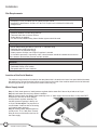
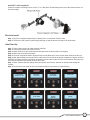
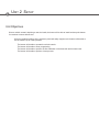
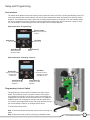
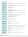
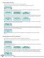
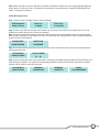
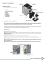
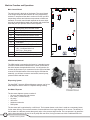
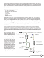
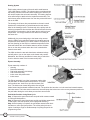
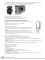
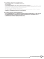
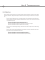
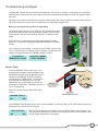
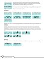
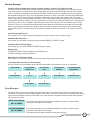
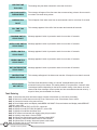
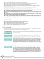
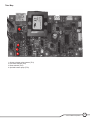
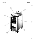
BUNN® TECHNICAL TRAINING
AutoPOD™
Index
Unit 1: Installation
Site Requirements............................................................................................................... 4
Location of the Serial Number........................................................................................... 4
Water Supply Install............................................................................................................ 4
AutoPOD™.................................................................................................................... 4
AutoPOD™ with pump................................................................................................. 5
Electrical Install................................................................................................................... 5
Initial Start-Up...................................................................................................................... 5
Unit 2: Setup
User Interface....................................................................................................................... 7
Switch/Display Board and Decal Button Layout........................................................ 7
Operation....................................................................................................................... 7
Programming Lockout Switch............................................................................................ 7
Programming Menus........................................................................................................... 8
Calibrating Flow Rate.......................................................................................................... 9
Brew Tank...................................................................................................................... 9
Hot Water Tank.............................................................................................................. 10
Coffee Brewing.................................................................................................................... 11
Unit 3: Machine Composition
Exterior Overview................................................................................................................ 13
Accessing the Inside of the Brewer................................................................................... 13
Machine Function and Operations..................................................................................... 14
Main Control Board....................................................................................................... 14
Dispensing System....................................................................................................... 14
Hot Water Tank........................................................................................................ 14
Brew Tank................................................................................................................ 15
Heating System............................................................................................................. 16
Ejector Assembly.......................................................................................................... 16
Unit 4: Preventive Maintenance
Preventive Maintenance...................................................................................................... 19
PM Steps.............................................................................................................................. 19
Unit 5: Troubleshooting
Service Tools....................................................................................................................... 22
Test Outputs.................................................................................................................. 23
Index Motor.................................................................................................................... 23
Water Inlet...................................................................................................................... 23
Warning Messages.............................................................................................................. 24
Error Messages.................................................................................................................... 24
Tank Draining....................................................................................................................... 25
Hot Water Tank Removal..................................................................................................... 26
Brew Tank Removal............................................................................................................. 26
Level 3 Programming.......................................................................................................... 27
Triac Map.............................................................................................................................. 28
Rev. B
© 2009 Bunn-O-Matic Corporation. All Rights Reserved
Unit 1 Installation
Unit Objectives
Given a realistic scenario depicting a new site install, the learner will be able to install and setup the brewer for
customer turnover without error.
Given a new machine, all the necessary tools and safety equipment, the learner will be able to install the brewer without error.
The learner will be able to verify that the site requirements have been met.
The learner will be able to locate and document the serial number.
The learner will be able to hook up the water supply to the AutoPOD™ and AutoPOD™ with Pump.
The learner will be able to power up and perform the initial set-up of the brewer.
Installation
Site Requirements
Space
• AutoPOD™ is only for indoor use on a sturdy counter or shelf
• AutoPOD™ dimensions is 15.8”H x 9.7” W x 15.2” D (40.1cm H x 24.6cm W x 38.6cm D)
• Weight 30 lbs
Water Treatment
• Sediment filtration to reduce large particles
• Taste and odor filter to remove chlorine
• Scale filtration as needed
• For best results a BUNN® Easy Clear® filtration system should be used
Plumbing
• Elbow adapter fitting provided to convert to ¼” male flare fitting
• Dedicate water supply with shut-off
• Connected to the cold water supply
• Water pressure 20-90psi, set to 50psi if regulator is needed
• If a backflow preventer is required by code, a shock arrestor should be installed close to the ma chine between the backflow preventer and the machine
Electrical
• 120VAC, 2 wire plus ground
• Dedicated 15Amp circuit breaker
• Receptacle within 5 feet of machine
Location of the Serial Number
The machine’s serial number is located on the data plate which is located on the lower front panel behind the waste
bin and drip tray. The serial number half tag can be found on the inside of the machine attached to the left side wall.
Removing top lid will give you access to the serial number only tag.
Water Supply Install
Step 1: Check water pressure, install pressure regulator before water filter if above 90 psi and set to 50 psi.
Step 2: Install water filter and purge before installation.
Step 3: Securely attach the adaptor elbow assembly to the ¼” water supply line from the filter. If using AutoPOD™
with pump it will have an elbow adapter
with a pressure regulator assembly. The
machine pressure regulator is factory set
at 10 psi; do not adjust. The purpose is to
accommodate locations with low incoming
or fluctuating water pressure.
Step 4: Securely attach adapter elbow assembly to the .75-11.5 NH (Hose Thread)
fitting at the rear of the brewer and turn on
the water supply.
4
AutoPOD™ Training Manual
AutoPOD™ with Pump Model
Pressure regulator with fittings secure to the .75-11.5 NH (Hose Thread) fitting at the rear of the brewer and turn on
the water supply
Electrical Install
Step 1: Plug-in the attached cordset from the brewer into a conventional 120VAC outlet.
Step 2: The brewer LCD (Liquid Crystal Display) will light up and the brewer is ready for the initial setup.
Initial Start-Up
Step 1: Place a large empty cup under the brew chamber.
Step 2: Connect the brewer to the power source.
Step 3: Water will flow into the Hot Water tank and stop when the tank is filled to its capacity.
Step 4: Open, then close door with switch.
Step 5: Press the Large Brew Switch. Water will flow into the Brew tank. Some excess water will flow into the cup.
Step 6: Wait approximately ten minutes for the water in the tank to heat to the proper temperature. Display will show
HEATING until tank reaches it’s operating temperature. Some water will drip from the brew chamber during this time;
this is due to expansion and should not occur there after.
Step 7: Water volumes and flow settings have been preset at the factory. Increase or decrease the settings as
needed.
Step 8: The brewer is now ready for use in accordance with the instructions for coffee brewing.
START-UP MODE
BREW TO FILL TANK
PLEASE WAIT
DOOR CLOSING
PRESS OPEN
TO LOAD POD
SELECT BREW
PLEASE WAIT
DOOR OPENING
PRESS CLOSE
BREWING
COMPLETE
HEATING
5
Bunn-O-Matic Corporation
Unit 2 Setup
Unit Objectives
Given a realistic scenario depicting a new site install, the learner will be able to install and setup the brewer
for customer turnover without error.
Given an installed machine, all the necessary tools and safety equipment, the learner will be able to set the machine up for initial operation.
The learner will be able to operate the switch controls.
The learner will be able to enter programming.
The learner will be able to perform the flow calibration of the brew tank and hot water tank.
The learner will be able to perform a brew process.
Setup and Programming
User Interface
The switch decal adheres to the front housing over the electronic switch and LCD (Liquid Crystal Display) board. The
mechanical switches are mounted directly onto the electronic board with a button mounted on the stem for product
actuation. The switch decal is nothing more than a overlay with description of the buttons. The user interface allows
the user to program the brewer for product recipes and begin the brew process with the selection of large or small
cup. The AutoPOD™ brewer also gives the user the option of a Hot Water dispense.
Switch Operation “Programming”
Hidden Switch
Step forward through
screens
Open/Close
Hot Water
“No” or (-)
Small Brew (B)
Step backwards
through screens
“Yes” or (+)
Large Brew (A)
“Done”
Switch Operation “Operating Controls”
Hot Water
Open/Close
Push and hold to
dispense hot water
only (Max 10 oz.)
Used to open and
close the pod
holder door
Small Brew (B)
Preset but can be
adjusted
Large Brew (A)
Preset but can be
adjusted
Programming Lockout Switch
The programming lockout switch is located on the main control
board. This switch can be set to prevent access to the programming settings of the brewer. Once all the correct brew settings are
programmed, the operator can set the switch to the “On” position to
prohibit anyone from changing the settings. With the switch in the
“On” position, the programming menus can still be accessed to view
the current settings. However, no changes will be saved.
To access the lockout switch:
Step 1: Disconnect brewer from power source before removing any
panel.
Step 2: Remove the rear panel by removing six standard screws.
7
Bunn-O-Matic Corporation
Programming Menus
BREW
LOCKOUT ?
NO DONE
YES
Brew Lockout
Prevents brewing if the water temperature is less than the “SET READY” temperature.
BREW
TYPE A
TEA DONE COFFEE
Brew Type (A/B) (Tea/Coffee)
Tea setting provides half the “purge” pressure as coffee at the end of brew cycle.
BREW
OZ A: 8.0
(-)
DONE
(+)
Brew Oz (A/B) (1-16 oz.)
Adjust brew volume.
BREW
METER A: 3
+
Brew Meter (A/B) (1-5)
Simplified pulse brew adjustment. 1=Preinfusion, 2-5=Pulse brew. 2 being the shortest pulse brew cycle and 5 being the longest.
ENTER
SERVICE #?
NO
YES
Enter Service #
Program service phone number to be displayed anytime there is a fault message.
ENTER
PASSWORD
0 0
0
Enter Password
User must enter a 3 digit password to access remainder of adjustments. If no number has been pre-programmed (000), then access is allowed.
SET
PASSWORD
0
0
0
Set Password (001-999)
Program any 3 digit number as a password.
SET
LANGUAGE ?
NO
YES
Set Language
Chose between English and Spanish.
UNITS
METRIC DONE
ENG
Units
Chose between English (Oz, ºF) or Metric (Ml, ºC).
SET
TEMP: 200O
(-)
DONE
(+)
Set Temp
Adjust tank temperature 185º F to 200º F (85º C to 96º C).
SET
READY: 195O
(-)
DONE
(+)
Set Ready
Sets the minimum temperature allowable to start a brew cycle. If BREW LOCKOUT is en
abled. Range: (2º F to 20º F) or (2º C to 10º C) below the set temperature.
HOT
H2O LOCKOUT ?
NO
DONE
YES
Hot H2O Lockout
Prevents a hot water dispense if water is not up to the H2O Ready temperature, if
enabled.
HOT
H2O TEMP: 200O
(-)
DONE
(+)
Hot H2O Temp
Adjust tank temperature 185º F to 200º F (85º C to 96º C).
H2O
READY: 195O
(-)
DONE
(+)
8
AutoPOD™ Training Manual
H2O Ready
Sets the minimum temperature allowable to start a hot water dispense.
ENTER ASSET # ?
NO
YES
Enter Asset #
Allows you to enter in an optional 4 digit number. This can be useful for tracking the us
age of an individual machine within a group.
SetPulseBrew
A/B
NO
DONE YES
Set Pulse Brew (A/B)
Individually adjust on/off times. This will override BREW METER.
AIR TIME A/B: 15.0
(-)
(+)
DONE
Air Time (A/B)
Time the brew tank is purged at the end of each brew cycle.
DRIP
TIME A/B: 15
(-)
(+)
DONE
DRIP TIME (A/B)
Time between brew cycle and pod ejection.
BREWS
TO EMPTY
(-)
(+)
25
Brews To Empty
Sets number of used pods need in bin to display “Empty Bin” message.
EnablEnergySavr
NO
DONE YES
Enable Energy Saver
Choose to have the tank heaters turn off, or reduce the tank temp to 140º F, (60º C) once the Set Idle Time has expired.
AIR PUMP POWER 4
(-)
(+)
DONE
Air Pump Power (1-4)
Adjust air pressure for end of brew cycle purge. Due to pod variations, reduce as needed if splattering occurs. Range is 1 to 4 with 1 being the weakest and 4 being the strongest.
BREW COUNT ##
NO
YES
Brew Count
Retains the total number of brew cycles completed, not resettable.
BREW COUNT ##
RESET NEXT
Brew Count
Retains the total number of brew cycles completed, resettable.
CALIBRATE FLOW ?
NO
YES
Calibrate Flow
Allows you to enter the actual flow rate of the sprayhead by dispensing for one minute. The volume is then entered in ounces per minute.
CalibrateMaximum
NO
H2O Time? YES
Calibrate Maximum H2O Time
Allows you to enter the ounces collected in flow test and calibrates the time it takes to deliver a 10 ounce H2O dispense.
NUMBER OF EJECTS
SINGLE
DOUBLE
Number of Ejects
Option of setting how many times is attempted to eject product before the next brew
cycle.
SEAL REPLACED ?
NO
YES
Seal Replaced
A preventive maintenance menu that is used to reset the factory setting of number of brews back to 4500 brews for next PM countdown.
SERVICE TOOLS ?
NO
YES
Service Tools
Allows testing of load components and switches. It should be only used by trained tech
nicians.
FACTORY DEFAULTS
NO
YES
Factory Defaults
Resets all brew settings, calibrations back to factory presets.
9
Bunn-O-Matic Corporation
Calibrating Brew Flow Rate
After initial start-up, the flow rate for the brew tank must be calibrated.
Step 1: Enter the program mode and scroll to the CALIBRATE FLOW menu and select YES.
CALIBRATE FLOW ?
NO
YES
Step 2: Menu screens will scroll displaying a message, !!!CAUTION!!! CONTAINER MUST HOLD 10 OUNCES.
Press large or small button to begin calibrating process.
!!!CAUTION!!!
CONTAINER MUST
HOLD 10 OUNCES
PRESS
BREW TO START
Step 3: The machine will display FLOW COUNTS and a “default flow count number 657” and will start delivering hot
water out the brew outlet. The flow count number will count down to zero and the water will stop. The machine will
display a message PLEASE WAIT until the next menu in step 4 is displayed.
FLOW COUNTS
657
FLOW COUNTS
0
PLEASE WAIT
Step 4: Enter the amount of ounces captured in your graduated measuring container into the menu screen utilizing
the -/+ buttons and press the center button under DONE.
ENTER OZ : 10.0
(-)
DONE
(+)
Step 5: The ounces entered in step 4 are being calibrated to the flow count number precisely to the amount of water
which was delivered during the calibrate flow test. The flow count number will change and will be set as the new calibration flow rate number into the control board assembly.
FLOW COUNTS/10 OZ.
643
Note: Reloading FACTORY DEFAULTS will erase the calibrated flow number and go back to the factory default
number.
Calibrating Maximum H2O Time (Hot Water)
After initial start-up, the maximum H2O time must be calibrated for the H2O tank.
Step 1: Enter the program mode and scroll to the, CALIBRATE MAXIMUM H2O TIME ?, menu and select YES.
CalibrateMaximum
NO H2O Time? YES
Step 2: Menu screens will scroll displaying a message !!!CAUTION!!!, “CONTAINER MUST HOLD 10 OUNCES and
PRESS HOT WATER TO START.
!!!CAUTION!!!
CONTAINER MUST
HOLD 10 OUNCES
PRESS HOT
WATER TO START
Step 3: Depress the Hot Water button one time and the brewer will start a timed hot water dispense. During this short
time the display will scroll the, CAUTION HOT WATER, message and stop displaying the message when the dispense is finished. The screen will now say, ENTER OZ 10.0. Enter the captured ounces and depress DONE button.
ENTER OZ : 10.0
(-)
DONE
(+)
10
AutoPOD™ Training Manual
Step 4: After entering the ounces collected, the machine changed the default time to the actual calibrated dispense
time to deliver 10 ounces of water. The display will revert back to the original menu, CALIBRATE MAXIMUM H2O
TIME?, to repeat test if needed.
Coffee Brewing Process
Step 1: Home screen will display a total of three messages.
AutoPod Brewer
Ready To Brew
Place Cup
To Begin
Press Open
To Load Pod
Step 2: Place cup under brew chamber onto booster tray or drip tray. The booster tray will allow up to 5 inch cup
clearance or bottom drip tray up to 8 inch cup clearance.
Step 3: Press the Open/Close switch to open the pod door and press a coffee pod firmly down into the pod holder.
Menu screens will prompt you through the process. The pod holder will accommodate a variety of pods and different
sizes from 50 to 61mm diameter.
PLEASE WAIT
DOOR OPENING
PRESS POD
IN DRAWER
Step 4: Press the Open/Door switch to close the pod door. Menu screens will prompt you through closing the door
and selecting brew size.
PLEASE WAIT
DOOR CLOSING
SELECT BREW
Step 5: After selecting brew, the menu screens will scroll brewing messages during the brew process and inform you
when brewing is complete. The system will automatically dispense the pod into the pod bin, reset back to standby
position and be ready for next brew command.
PLEASE WAIT
PRE-INFUSION
BREWING
PLEASE WAIT
BREWING
COMPLETE
ENJOY
YOUR BEVERAGE
11
Bunn-O-Matic Corporation
Unit 3 Machine Composition
Unit Objectives
Given a realistic scenario in which the learner has access to the machine’s internal components the learner
will understand the composition and functions of the brewer.
Given a realistic scenario requiring the learner to access the internal components of the machine the learner will be able to remove the front panel and top cover.
The learner will disconnect the electrical and water supply.
The learner will remove the front panel and top cover.
Given an operating machine the learner will be able to give a general explanation of how the unit operates.
The learner will be able to identify the functions of the main control board and identify the
components that correspond to each triac.
The learner will be able to identify the components and functions of the hot water tank dispensing system.
The learner will be able to identify the components and functions of the brew tank dispensing system.
The learner will be able to identify the components and functions of the heating system.
The learner will be able to identify the components and functions of the ejector assembly.
Machine Composition
Exterior Overview
Product Outlets and Removable Parts
•
•
•
•
•
•
•
•
Pod Door
Drip Tray and Grate
Booster Tray and Grate
Pod Bin
Top Cover
Rear Panel
Main Housing
Switch Decal
Accessing the Inside of the Brewer
The majority of service work done to the AutoPOD™ brewer will require the service technician to access the inside of
the unit. The brewer has three removable panels to facilitate access- the main housing, top cover and rear panel.
Depending on the repair the technician may have to remove one or all of these panels.
In order to work safely the power should be disconnected prior to removal of any body panel. Once the panels are
removed the power can be reconnected in order to troubleshoot the machine.
Remove Panels
Step 1: Disconnect unit from power.
Step 2: Use a standard screwdriver and remove the two screws from the top cover of the unit. Lift the top cover up
and away from the unit.
Step 3: Move the rear of the unit and remove the six standard screws securing the back panel. Pull the panel back
and away from the unit.
Step 4: Return to the front of the unit and pull the pod bin out and set aside.
Step 5: Locate the three standard screws found on the bottom edge of the unit below the user interface.
Step 6: Turn the unit so that the right side is facing you. Tilt the unit upward to access the underside and remove the
right side standard screw.
Step 7: Turn the unit so that the left side is facing you. Tilt the unit upward to access the underside and remove the
left side standard screw.
Step 8: Turn the unit so that the front is facing you and then slide the main housing out away from the unit frame.
13
Bunn-O-Matic Corporation
Machine Function and Operations
Main Control Board
The main control is the brain of the brewer. The control board
is the single component that contains all of the programming
software, it interprets all the data it receives from the level and
temperature sensors and activates components to fulfill those
demands. The main control board responds to the users input
through the switch/display board and activates and controls the
brew and pod eject process and hot water dispense.
J1
Reed Switch and H2O Refill Probe
J2
Brew Tank Thermistor
J3
Heater Relay Coil and Air Vent Coil
J4
Index Sensor and Pressure Switch
J5
xxxxx
J6
Switch/Display Board
J7
Flow Meter
J8
Index Motor & Air Pump Brew Tank
J9
BR- Brew Inlet Valve Coil
HW – Hot Water Valve Coil
BST Pmp – Brew pump
J11
Hot Water Tank Thermistor
J12
Air Pump Hot Water Tank (H2O)
1 2 3 4
J4
J7
1
2
3
4
5
J11
2 1
J1
PRGM
LOCK
SET
6 5 4 3 2 1
ON
J2
SW1
J3
2 1
J5
4
3
2
1
J6
1
2
3
J12
J8
1
2
3
4
1
2
BR HW BST
SOL SOL PMP
CBA Bracket Removal
The CBA bracket is mounted to the frame by 3 standard screws.
2 screws located bottom underside and 1 screw located above
the white harness clamp behind the wires. You will need to disconnect the flow meter 3-pin connector from the CBA to facilitate
removal of CBA with bracket. After removing the CBA bracket
assembly, you will have access to reed switch, brew air pump,
pressure switch and flow meter.
Dispensing System
The AutoPOD™ has two different dispense systems, one for hot
water dispense and the other for a dispense during brewing.
Hot Water Dispense
The hot water dispense system consists of:
• 20 ounce hot water tank with element
• Inlet valve (.175 flow control)
• Air pump
• Vent valve
• Stainless outlet tube
• Refill probe
14
The hot water tank is maintained by a refill circuit. The hot water button on the front is used as a momentary button
for hot water delivery. The maximum amount of ounces delivered in a single dispense is 10 ounces. The delivery of
the hot water is a different process than gravity style or line pressure style faucets. The new process is by pressurizing the hot water tank by the use of an air pump and vent valve, forcing hot water out within a calibrated flow time.
AutoPOD™ Training Manual
Water enters the inlet valve and is regulated by a .175 flow control and enters the bottom of the hot water tank. The
tank will fill with water to refill probe level and will heat to the adjusted temperature, which can be set in programming.
When a user press and holds the momentary hot water button, the air pump will turn on for calibrated period of time
to pressurize the tank while the vent valve closes to deliver a 10 ounce portion of hot water.
Brew Tank Dispense
The brew tank dispense system consists of:
• Inlet valve (.175 flow control)
• Optional booster pump (set at 10psi)
• Flow meter
• Pressure switch
• Air pump
• Brew tank
• Sprayhead assembly
The brew tank is initially filled upon startup and monitored by flow counts from the flow meter. Once the tank has
met its flow count number the machine will begin heating the brew tank. At this point, the incoming brew water will
displace the 200º F water in the brew tank which will maintain a level of water in the tank when commanded by the
portion buttons. The large and small buttons are adjustable by volume and recipe (coffee or tea) in the programming
menus. The volume or portion dispense size is calculated from flow default meter counts. This is why its important
to calibrate the brew flow upon placement of the machine to the actual amount of brew water delivered during the
calibrate flow test. The BUNN® default dispense value is 10 ounces during this calibration test. Once the actual flow
amount is entered in programming, the machine will automatically adjust the flow count number to achieve a 10
ounce dispense.
During a dispense water enters the inlet valve and is regulated by .175 flow control and enters a booster pump,
(Not all AutoPOD™ units have a booster pump; product number specific), which is capable of 50psi. The pump is
intended for low water pressure applications. With some heavier/finer grind pods that require more pressure to brew,
if the pressure gets below 25-30psi they will brew slower. The pump will boost the incoming water pressure to a high
enough level to brew normally. These pumps can create 50+psi, but the pod will determine the actual brewing pressure.
After the booster pump, water enters the inlet of the flow meter and
pushes the paddle wheel and exits
out the flow meter and connects to
the four way plumbing fitting and
continues onto the bottom fitting of
the brew tank. A pressure switch
connects directly opposite of the
water inlet on the 4 way fitting. The
pressure switch is calibrated to approximately 40psi. The purpose is
to monitor the pressure during the
coffee brewing process. If pressure should exceed the 40psi in the
brew head assembly, the machine
will abort the brew and display an
error code. After every brew cycle,
the machine will go through a
sequence of running the air pump
longer to empty the sprayhead tube
of any brew water and stop. The
machine will now be ready for the
next brew.
15
Bunn-O-Matic Corporation
Heating System
Each heating element is part of the tank and is rated between
1300-1450 watts at 120VAC. The element wires are soldered onto
the heating element terminal and when replacing the element you
will need to replace the entire tank assembly. The heating element
wires will already be attached to the replacement assembly. The
tank element wires will disconnect from the relay contact and terminal on the CBA.
The heating circuit has a relay mounted above the main control
board and is used primarily to switch between the tank assemblies for the heating process. The brew tank is the priority tank for
achieving temperature first and then the CBA will activate the relay
and switch the connection to the hot water tank to achieve its set
temperature. The relay prevents the two tanks from heating at
the same time.
Additionally, the power lead going to the heater relay contact
from the CBA is being switched between the two tanks and can
be pulsed at times and be full on when needed. The purpose of
the triac (heating) on the CBA is to maintain temperature of the
brew tank without the use of blanket warmers and to eliminate
the arc on the relay contacts when the circuit is switched between the two tanks.
The CBA monitors the two tank thermistors resistance/voltage
and will pulse or turn on the output to the heater relay contact.
Meanwhile, the CBA may activate the heater relay to switch the
circuit to heat the water in the hot water tank (H2O).
Ejector Assembly
Ejector assembly consists of:
• Housing
• Brew head assembly
• Pod holder assembly with linkage
• Pod screen assembly
• Index motor with position disc
• Index sensor
The Ejector assembly is a critical component used to align
the pod holder in different placement positions. The placement positions are: load, brew, eject and set back positions. The index motor rotates the position disc and pod
holder forward and backward at different intervals. The position disc has slots cut in the metal and rotates between
the index sensor. The index sensor monitors the slots and stops the index motor at the correct placement position for
the pod holder during the entire brew process from start to finish.
Pod Holder Position during Brew Cycle
Step 1: Depress the open/close button and pod holder rotates outward
to coffee pod load position.
Step 2: Depress the open/close button and the pod holder rotates back
in and stops in the brew position (under sprayhead assembly).
Step 3: After brewing is complete, the pod holder rotates further back
and down to coffee pod eject position. The coffee pod eject has an
option of making a single or double attempt of ejecting the pod in the
programming menu.
16
AutoPOD™ Training Manual
Step 4: After ejecting the coffee pod, the pod holder rotates forward by a set time built in the software (approx. 5 seconds) and stops at the set back position from the sprayhead assembly and is ready for the next brew command.
Ejector Assembly Removal
The Ejector assembly will be replaced as an entire service replacement part if the index motor will not work and
needs to be replaced. The assembly has too many critical adjustments (timing) when replacing the index motor for
correct operation of the brew and pod eject process. The following steps will not take longer than 30 minutes to
change out an Ejector assembly.
Step 1: Disconnect power to the brewer.
Step 2: Remove top cover (2 screws) and rear cover (6 screws).
Step 3: Disconnect the black 4 pin wire connector on the Switch/Display board.
Step 4: Disconnect the 2 pin wire connector going to the index motor.
Step 5: Disconnect the 3 pin wire connector at the index motor sensor.
Step 6: Remove the snap clamp (SN P6) and braided hose from the sprayhead assembly fitting labeled “W”.
Step 7: Remove the silicone air vent hose from the rear hole of the Ejector assembly.
Step 8: Remove the silicone hot water supply hose routed up by the Switch/Display board which enters the access
hole on the side of the Ejector panel. Pull hose from fitting.
Step 9: Remove the main wrapper housing by 3 screws located underside of the Display or Pod door, 2 screws on
the underside center base bottom.
Step 10: Grab the left and right side of the housing at the rear and spread apart and pull away from main trunk
frame.
Step 11: The Ejector assembly is now ready to be removed. The Ejector is attached to the main trunk frame by 1
standard screw located on each outer side of the tanks. You will need to grab the upper sprayhead assembly while
removing the screws keeping the Ejector from falling free.
17
Bunn-O-Matic Corporation
Unit 4 Preventive Maintenance
Unit Objectives
Given a realistic scenario depicting a machine requiring a preventive maintenance, the learner will be able to
identify which elements of a component need to be serviced without error.
Given a machine, all the necessary tools and safety equipment, the learner will be able to identify the components that need to be serviced for the PM.
Preventive Maintenance
In order to maintain proper operation and long service life BUNN® recommends performing the preventive maintenance every 6 months. Individual customers will vary with some customers choosing not to receive preventive maintenance. Some of the PM items may require more frequent maintenance depending on the site conditions.
Tools Required:
• 2 standard screwdrivers (1 small tip & 1 medium tip)
• Needle nose pliers
• Pliers
• 2, 8 inch crescent wrench
• Graduated measuring cup
• Tube Brush (.25 0D), BUNN P/N: 26367.0000
PM Parts:
• Sprayhead Seal, BUNN PN: 42310.0000
• Water filter or cartridge
• Refill probe grommet, BUNN PN: 33201.0000
• Pod Screen Assembly BUNN PN: 40806.1000
Prior to servicing the brewer:
• Depress open/close door switch to open door before disconnecting from power.
• Disconnect the water and electrical supply.
• Assess placement of brewer to perform PM process.
• Allow brewer tanks time to cool down.
• Remove top cover and rear panel.
PM Steps
If customer has a BUNN® water filtration system installed before the brewer, replace the filter or filter cartridge and
purge before installing to the brewer.
Note: PM Steps 1 and 2 will require the machine to be plugged in to access the “Test Outputs” screen in programming.
Step 1: Cleaning sprayhead and replacing seal
□□ Press and hold the hidden programming button (under “BUNN”) until display reads “Brew Lockout”
□□ Press and release the “Small” brew button until display reads “Service Tools”. Select “Yes”
□□ Display should read “Test Outputs?” Select “Yes”. Display should now read “Index B Motor”. Press and hold “Load” (Hot Water) button until pod holder pushes the door open.
□□ Unscrew sprayhead counterclockwise
□□ Remove sprayhead and seal
□□ Check and clean sprayhead. The sprayhead holes must always remain open. Clean all the holes in the plastic sprayhead to remove any mineral deposits or coffee oil build up
□□ Install new sprayhead seal (BUNN P/N: 42310.0000) onto clean sprayhead
□□ Re-install sprayhead with gasket. Make sure seal is installed with the ridge facing up
□□ Remove and clean pod screen assembly of coffee oil build up. Replace pod screen if missing (BUNN P/N: 40806.1000)
Step 2: Clean the stream guide bowl
□□ Use a screwdriver or similar object to hold door open.
□□ Press and hold “Dump” (Open/Close) button until pod holder moves back and just clears the stream guide bowl.
□□ Disconnect brewer from power supply.
□□ Remove drip tray and pod bin by pulling straight towards you
□□ Remove stream guide bowl cap by prying up on seam
19
Bunn-O-Matic Corporation
□□ Insert 26367.0000 cleaning brush from the underside into the coffee outlet hole (rear) and work back and forth
□□ Use clean wash cloth and wipe out the lower stream guide bowl and the cap removed earlier
□□ Reinstall bowl cap by aligning the tab and notch and snapping back into position
Step 3: Clean drip tray and pod bin removed earlier
□□ Separate the parts and wash with mild nonabrasive liquid detergent
□□ Reassemble components and install when PM is complete
Step 4: Remove inlet valve connector fitting and clean inlet valve strainer
□□ Using your hand and unscrew the valve adapter fitting and set aside
□□ Using the needle nose pliers gently grab the strainer tab and pull the strainer out of the valve
□□ Clean and rinse strainer of any sediment or mineral build-up
□□ Reinstallation is the opposite of removal
Step 5: Remove and clean refill probe
□□ Remove refill probe with the pink wire attached by gently prying upward with a stan
dard blade screwdriver or by the use of pliers and pull tightly fitted probe out of grom
met
□□ Clean the refill probe of any mineral build up. Use of a deliming solution is recom
mended
□□ Install clean refill probe with pink wire back into grommet. Warning – Do not push grommet into tank! Wet the refill probe and gently rotate back and forth while pushing the probe downward until it stops
Step 6: Remove and clean thermistor in each tank
□□ Disconnect the thermistor 2 pin connector from the CBA labeled “Hot Water”
□□ Disconnect the thermistor 2 pin connector from the CBA labeled “Brew Tank”
□□ Remove bottom snap clamp from each of the braided tube with the thermistor and remove braided tube with the thermistor from each tank
□□ Clean both thermistors of any mineral build up. Use of a deliming solution is recommended. Do Not Immerse the Wires!
□□ Reinstall clean thermistors
□□ Re-connect the thermistor 2 pin connectors back onto the CBA in their appropriate labeled connectors
Step 7: Calibrate the flow for the Brew tank
□□ Install top cover and rear cover
□□ Reinstall water and connector fitting
□□ Reinstall power
□□ Reinstall pod bin & drip tray
□□ Access programming and go to CALIBRATE FLOW ? menu
□□ Depress YES button
□□ Place graduated measuring cup (minimum 10 ounces) under coffee outlet
□□ Follow the instruction on the display
□□ After dispense finishes, read number of ounces and enter that amount into brewer using the +/- switches, then press DONE to set the volume into memory
20
AutoPOD™ Training Manual
Step 8: Calibrate the maximum H2O (Hot Water Tank) time
□□ Access programming and go to CALIBRATE FLOW ? menu
□□ Depress NO button
□□ CALIBRATE MAXIMUM H2O TIME ? will be displayed. Depress the YES button
□□ A series of informational screens will scroll and an instruction screen will display PRESS HOT WATER TO START
□□ Place graduated measuring cup (minimum 10 ounces) under outlet
□□ Depress the hot water to begin the calibration process
□□ After dispense finishes, read number of ounces and enter that amount into the brewer using the +/- switches, then press DONE to set the H2O time for a 10 ounce dispense
□□ Scroll through the remaining program menus to exit programming
Step 9: Perform a coffee brew test and H2O dispense test
□□ Follow “Operation” procedure in the Installation and Operating Guide for coffee brewing and hot water dispensing
□□ Check levels against large and small brew ounce settings in the program menus “Brew OZ. A & Brew Oz B”
□□ If ounces are off then repeat the calibration procedure in step 7
□□ Check H2O dispense level for 10 ounce dispense
□□ If ounces are off then repeat the calibration procedure in step 8
21
Bunn-O-Matic Corporation
Unit 5 Troubleshooting
Unit Objectives
Given a realistic scenario depicting one of several possible machine malfunctions, the learner will be able to
effectively troubleshoot, diagnose and repair the malfunction before returning the machine to normal operation.
Given a machine displaying an error or warning message, all the necessary tools and safety equip
ment, the learner will be able to access the software and use “Service Tools” menu as a tool to assist in the diagnosing process.
The leaner will be able to access the programming menu.
The learner will be able to navigate to the Service Tools menu.
The learner will be able use the Service Tools menu to test inputs or outputs.
The learner will be able use the Test Switches menu for testing.
Given a list of error and warning messages, the learner will be able to explain the error and warning messages.
Given a realistic scenario requiring diagnosis and the leaner to remove the assemblies, the learner will be able to remove the assembly without error.
The learner will be able to remove and re-install the brew tank.
The learner will be able to remove and re-install the hot water tank.
The learner will be able to remove and re-install the ejector assembly.
Troubleshooting and Repair
The AutoPOD™ brewer features on-board troubleshooting. Since all of the machine’s components are controlled or
activated by the control board you can activate and test load components individually from the user interface to test
the inputs.
This allows you to listen to solenoid valves opening, observing the flow of water, switches operating, sensors operating, motor movement or test to see if a component is receiving voltage using a meter.
Memory is Locked Accessing Level 1 Programming
The program lockout switch is set to keep you from entering the program
menus and prohibit anyone from changing the settings. The menus can
be accessed to view the current settings. However, no changes will be
saved.
Enter the Level 1 Programming by pressing and holding the “Hidden
Switch” for 3 seconds or until display reads BREW LOCKOUT and then
release.
If the “Program Lockout Switch” is turned to the On position and you enter
Level 1 Programming, the following menus will display, reminding you the
memory is locked, and stop on the BREW LOCKOUT screen.
!!! CAUTION !!!
MEMORY IS LOCKED
CONSTANT CHANGE
IS NOT POSSIBLE
Service Tools
To access SERVICE TOOLS enter Level 1 Programming without lockout switch activated. Once
the BREW LOCKOUT menu is displayed, you will
navigate to the SERVICE TOOLS by pressing
and releasing the “Hidden Switch” consecutively.
If you pass the intended menu, you can step
backwards in the programming by pressing and
releasing the “Small Brew” switch while you are in
Level 1 Programming.
Select YES to enter into the SERVICE TOOLS
function.
SERVICE TOOLS ?
NO
YES
In the SERVICE TOOLS selection their are 3 screens available, by selecting YES, you will enter that test function, by
selecting NO you will move to the next test.
TEST OUTPUTS?
NO
YES
TEST OUTPUTS will give you the option of turning On and Off the output voltage to the load component individually. A voltmeter can be used across the load component to mea
sure the output voltage when commanded.
23
Bunn-O-Matic Corporation
TEST SWITCHES?
NO
YES
TEST SWITCHES will give you the option of pressing the control switch individually and displaying the switch name on the display screen for switch recognition. Pressing the “Hidden Switch” will exit and advance you to the next screen.
FACTORY BLOWOUT?
NO
YES
FACTORY BLOWOUT will prompt additional menu screens taking you through the steps of draining the brew and hot water tanks for tank service replacement or storage of the equipment during the winter months.
Test Outputs
INDEX
MOTOR
DUMP NEXT
LOAD
EXTERNAL RELAY
WATER INLET xxx
ON
ON
HOT WATER
ON
NEXT
OFF
NEXT
OFF
VENT VALVE
ON
NEXT
OFF
NEXT
OFF
HOT WATER AIR PUMP
ON
NEXT
OFF
AIR PUMP
ON
NEXT
OFF
TANK HEATER
CANNOT TEST
TANK HEATER
TEMP TOO HIGH
Two of the TEST OUTPUT screens test the input signal from a component at the same time you are testing the load
component.
Index Motor
The filled in black square means the position disc is interrupting the index sensor (blocked). The unfilled square
means the position disc is not interrupting the index sensor or position disc slot is lined up with the index sensor
(unblocked). The “Dump” and ‘Load” switches are used as a momentary button. You will need to press and hold the
switch to rotate the index motor, which will automatically stop at the corresponding test position or slot in the position
disc.
INDEX
MOTOR
DUMP NEXT
INDEX D
LOAD
MOTOR
DUMP NEXT
LOAD
INDEX
MOTOR
DUMP NEXT
INDEX L
LOAD
INDEX B
MOTOR
DUMP NEXT
LOAD
MOTOR
DUMP NEXT
LOAD
Water Inlet
The water inlet test screen when activated will allow water to flow out the brew tank sprayhead outlet and display
increasing flow count number at the same time. The flow count number is the signal input from the metering pulses of
the volumetric meter (flow meter).
WATER INLET 0
ON
NEXT
OFF
24
AutoPOD™ Training Manual
WATER INLET 657
ON
NEXT
OFF
Warning Messages
Pressure switch activation during single cup brew, displays “Pressure Too High on the LCD”
The brew process is monitored by a pressure switch that is located in the incoming water line to the tank. The purpose of the switch is to detect pressure above 45psi above the coffee during the brew process and abort the brew
cycle to eliminate the possibility of exceeding the limitation of the brew seal. Two variables come in play regarding
the troubleshooting process. First, incoming high water pressure is a factor to be ruled out during initial troubleshooting of the error fault “Pressure Too High”. Generally, locations do not have high water pressure, but in the event a
location is pushing the recommended psi limitation in the manual (90psi) a factory set (50psi) pressure regulator can
be purchased from Bunn-O-Matic. The second variable you need to keep in mind is the product itself. The weight and
grind of the product is also a variable in determining the pressure. Even though you have moderate high incoming
pressure of 70psi, you could still activate the pressure switch because of the water not being able to push through
quick enough causing back pressure to build up above the coffee and back to the pressure switch. Another thing
to remember, factor in a tolerance range of opening the electrical connection in the switch. The range can be 40 to
45psi.
Cannot Brew High Pressure
Occurs when the J4-4 input is high when starting a brew cycle (pressure switch contact is open).
Pod Waste Bin Almost Full
Occurs when you are within 5 brews of the programmable BREWS TO EMPTY setting.
Pod Waste Bin Full Please Empty
Occurs when you are at the BREWS TO EMPTY program setting.
Replace Seal
The REPLACE SEAL SOON message occurs at 4500 brews.
The NOW message occurs at 5000 brews.
Waste Bin Removed Please Install
Occurs when J1-4 connector terminal has a low input when trying to start a brew cycle.
Low Temperature Press Brew To Brew Anyway
Occurs, (if brew lockout is disabled), when the water temperature in the brew tank is not up to temperature.
CANNOT BREW
HIGH PRESSURE
POD WASTE BIN
REPLACE SEAL
POD WASTE BIN
LOW TEMPERATURE
ALMOST FULL
SOON
REMOVED
PRESS BREW
!!! FULL !!!
!!! NOW !!!
PLEASE INSTALL
TO BREW ANYWAY
PLEASE EMPTY
SEAL REPLACED ?
Error Messages
The brewer has several error messages for problems that may occur in the machine. The error screen is basic the
information on getting you started in diagnosing the actual failure. Some error messages will need resetting by following the screen prompts to reset error fault (erase) or you will need to fix the problem and the machine will automatically reset the error fault.
BREW TEMP SENSOR
OUT OF RANGE
If the control board loose contact with the temperature sensor or senses shorted
connection it will display this message.
HOT WATER SENSOR
OUT OF RANGE
If the control board loose contact with the temperature sensor or senses shorted
connection it will display this message.
The heating relay has been activated for more than 6 minutes.
25
Bunn-O-Matic Corporation
HEATING TIME
The heating relay has been activated for more than 6 minutes.
TOO LONG
NO FLOW
COUNTS
The message will appear if the flow meter has not metered any pulses or flow counts for more than 5 seconds during a brew.
DURING BREW
INDEX MOTOR
FAULT
This will appear if the index motor has not encountered a slot for more than 15 seconds.
This message appears if the refill of the hot water tank exceeds 90 seconds.
TIME
FILL
TOO
LONG
PROGRAM SWITCH
STUCK FAULT
Message appears if switch is pressed or stuck for more than 15 seconds.
OPEN CLOSE SWITCH
STUCK FAULT
Message appears if switch is pressed or stuck for more than 15 seconds.
BREW A SWITCH
STUCK FAULT
Message appears if switch is pressed or stuck for more than 15 seconds.
BREW B SWITCH
STUCK FAULT
Message appears if switch is pressed or stuck for more than 15 seconds.
HOT WATER SWITCH
STUCK FAULT
Message appears if switch is pressed or stuck for more than 25 seconds.
OBSTRUCTION
PRESS OPEN-CLOSE
This message will appear if the index motor reaches .55 amps for more than 3 seconds.
PATH CLEAR ?
ANY SWITCH
The Path Clear threshold is actually a “Learned” threshold based upon the last
successful closing of the drawer. The starting default .27 amps and the “Learned” value is raised and lowered depending on the last successful closing of the drawer. Once the learned Path Clear message comes up when we have exceeded the learned value by .1 amps for 20ms (one thousandth of a second).
Tank Draining
26
Step 1: Disconnect the power and water supply to brewer. Allow brewer to cool before proceeding.
Step 2: Remove 2 screws that secure the top cover. Remove the cover. Place brewer next to a sink.
Step 3: Connect the brewer to the power source.
Step 4: Press hidden switch until display reads BREW LOCKOUT. Press and release until display reads SERVICE
TOOLS?; select YES.
Step 5: Display will read TEST OUTPUTS?; select NO.
Step 6: Display will read FACTORY BLOWOUT?; select YES.
Step 7: Display will read Blow Out Brew Tank.
Step 8: Tilt brewer back towards sink slightly during this procedure!
Step 9: Carefully clamp hose A. Select START.
Step 10: When brew tank blowout mode is finished, select NEXT.
Step 11: Carefully clamp the Hot Water hose B. Select START.
Step 12: When tanks are empty, disconnect power to the brewer.
Step 13: Replace the top cover and tighten screws.
AutoPOD™ Training Manual
Hot Water Tank Removal
The hot water tank will need to be replaced when the heating element no longer works.
Step 1: Disconnect power to the brewer.
Step 2: Remove top cover (2 screws) and rear cover (6 screws).
Step 3: Drain tank by following procedures written in the Installation and Operating Guide or disconnect snap clamp
from braided tube with the thermistor and remove braided tube with thermistor from the tank fitting. Turn brewer over
sink and water will drain out of the tank slowly.
Step 4: Position brewer onto countertop with the rear facing you and tilt the machine forward until it rests on the front
edge bottom.
Step 5: Disconnect the red wire to the limit thermostat.
Step 6: Disconnect the 2 ground wires attached to the bottom of the tank via
11/32 nut and lock washer.
Step 7: Disconnect the white wire with the ¼ inch spade terminal at the bottom of the CBA that connects to one side
of the tank heater.
Step 8: Remove refill probe with the pink wire attached by gently prying upward with a standard blade screwdriver or
by the use of pliers and pull tightly fitted probe out of grommet.
Step 9: Remove stainless tube out of the grommet with the silicone hose attached by pulling upward out of the grommet.
Step 10: Disconnect the thermistor 2 pin connector from the CBA labeled “Hot Water”.
Step 11: Remove bottom snap clamp from the braided tube with the thermistor and remove braided tube with the
thermistor from the tank fitting.
Step 12: Remove snap clamp off the center tank fitting and pull silicone hose off the tank fitting.
Step 13: Remove snap clamp off of bottom silicone hose and pull hose from bottom tank fitting.
Step 14: Mark or make note on how the hot water tank is orientated in the machine. Remove the 2 standard screws
from the tank mounting band and remove tank.
Step 15: Disconnect the black wire from the limit thermostat and remove limit thermostat by gently prying the holding
clamp upward and remove limit thermostat.
Hot Water Tank Re-install
Step 1: Install limit thermostat from step 15 removal process.
Step 2: Install refill probe with pink wire from step 7 removal process.
Warning – Do not push grommet into tank! Wet the refill probe and gently rotate back and forth while pushing the
probe downward until it stops.
Step 3: Install stainless tube from step 9 removal process. The stainless tube height out of the grommet should be
line horizontally with the metal tank fitting or approximately 5/8” of stainless tube above grommet.
Warning- Do not push grommet into tank! Wet the stainless tube and gently rotate back and forth while pushing the
stainless tube to the appropriate height level.
Step 4: Install bottom silicone fill hose from step 13 removal process.
Step 5: Orientate the hot water tank and re-install from step 14 removal process.
Step 6: Install silicone vent hose from step 12 removal process.
Step 7: Install thermistor and braided hose from step 11 removal process.
Step 8: Connect thermistor 2 pin connector from step 10 removal process.
Step 9: Connect ground wires from step 6 removal process.
Step 10: Connect white wire from step 7 removal process.
Step 11: Connect red wire from step 5 removal process.
Brew Tank Removal
The brew tank will need to be replaced when the heating element no longer works.
Step 1: Disconnect power to the brewer.
Step 2: Remove top cover (2 screws) and rear cover (6 screws).
Step 3: Drain tank by following procedures written in the Installation and Operating Guide or disconnect snap clamp
from braided tube with the thermistor and remove braided tube with thermistor from the tank fitting. Turn brewer over
sink and water will drain out of the tank slowly.
Step 4: Position brewer onto countertop with the rear facing you and tilt the machine forward until it rests on the front
edge bottom.
Bunn-O-Matic Corporation
27
Step 5: Disconnect black wire from limit thermostat going to heater relay.
Step 6: Leave all wires connected to relay and remove relay from CBA mounting bracket via 2 screws.
Step 7: Disconnect the thermistor 2 pin connector from the CBA labeled “Brew Tank”.
Step 8: Remove bottom snap clamp from the braided tube with the thermistor and remove braided tube with the
thermistor from the tank fitting.
Step 9: Remove snap clamp from center top braided hose and remove braided hose from tank fitting.
Step 10: Disconnect the flow meter 3 pin connector at the main control board labeled “J1”.
Step 11: Remove the CBA with bracket from the trunk frame by 3 standard screws. 2 screws are located bottom
underside and 1 screw located above the white harness clamp behind the wires.
Step 12: Rotate the CBA with bracket to the right exposing the entire brew tank assembly.
Step 13: Remove the snap clamp off the braided inlet hose on the center bottom fitting and pull off braided hose from
tank fitting.
Step 14: Disconnect the white wire with the ¼ inch spade terminal from the piggy back terminal on the white cord set
wire going to the bottom terminal connection on the CBA labeled “L2”.
Step 15: Mark or make note on how the brew tank is orientated in the machine. Remove the 2 standard screws from
the tank mounting band and remove tank.
Step 16: Disconnect the black wire from the limit thermostat and remove limit thermostat by gently prying the holding
clamp upward and remove limit thermostat.
Brew Tank Re-Install
Step 1: Install limit thermostat and black wire from step 16 removal process.
Step 2: Install braided inlet hose from step 13 removal process.
Step 3: Orientate the brew tank and re-install from step 15 removal process.
Step 4: Continue with the remaining removal steps in reverse order.
Level 3 Programming
Access the Level 3 Programming menus by pressing and holding the hidden button for approximately 13 seconds or
until the menu changes from “Brew Lockout” menu to “Cal Temperature” menu.
CAL TEMPERATURE
NO SENSORS YES
Used to accurately set the temperature along with a calibrated thermometer when replac
ing the tank thermistor.
WATER
PUMP
POWER
(-) 50
(+)
Power adjustment for lowering or raising the motor rpm. Used in setting the flow rate over the coffee pod if the PRESSURE TOO HIGH warning appears due to issues with heavy/fine grind coffee pods.
SELECT PROBE TYPE
METAL
PLASTIC
Menu to select early or late version of thermistor being used. Current probe being used is the metal probe. The thermistor probe mounts in the top of the tanks. Old style plastic thermistor probes installed in the side of the tanks. Selecting a probe type has a direct relationship with the “Relay Off After Brew” menu. The purpose of the menu is to support the early version AutoPOD™ model with the plastic thermistor probes when replacing a main control board.
RELAY OFF AFTER BREW
(-)
12
(+)
The adjustment menu is used to set when the heater full on current will switch to triac control to pulse the current to the element without over running the temperature set
point. The type of thermistor used in early and late AutoPOD™ model has a different
default number. If you select a probe type between metal and plastic this will automati
cally set the default number for the “Relay Off After Brew” menu. Metal probe is defaulted to 12 (current version). Plastic probe will default to 18 (early version). Do not adjust the default number. If the number is changed from the default number, the heating recovery time is affected for the brew and hot water tank.
28
AutoPOD™ Training Manual
Triac Map
1
2
3
4
1. Output to heater relay contacts (TH1)
2. Hot water solenoid (TH2)
3. Brew solenoid (TH4)
4. Optional booster pump (TH3)
29
Bunn-O-Matic Corporation