1
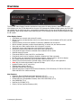
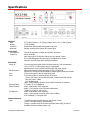
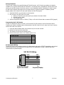
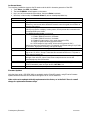
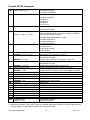
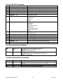
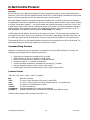
Product Manual ICC2-VDC Video Display Controller Ver. 8.1 December 17, 2012 4355 Excel Pkwy, Suite 600, Addison, TX, 75001 Phone:972-931-2728 • Toll-Free: 888-972-2728 • Fax: 972-931-2765 E-Mail: [email protected] • Website: www.crwww.com Table of Contents Overview ............................................................................................................................................. 3 Video Display Control ................................................................................................................................ 3 Specifications ...................................................................................................................................... 4 Physical ................................................................................................................................................... 4 Front Panel .............................................................................................................................................. 4 Rear Panel ............................................................................................................................................... 4 Internal Closures ...................................................................................................................................... 4 RF Tuner.................................................................................................................................................. 5 ICC-Net ................................................................................................................................................... 5 Status Indication ...................................................................................................................................... 5 Accessories .............................................................................................................................................. 5 Installation ......................................................................................................................................... 6 AC Power ................................................................................................................................................. 6 RF Coax and iCC-Net Operation ................................................................................................................. 6 RS-232 Control Wiring .............................................................................................................................. 6 A/V Setup ................................................................................................................................................ 6 External IR Sensor .................................................................................................................................... 7 Programming the IC-RC Remote ................................................................................................................ 7 RS-232 Control Wiring .............................................................................................................................. 7 On-Screen Menus ..................................................................................................................................... 8 Firmware Updates .................................................................................................................................... 8 Projector/Monitor Control Codes ........................................................................................................ 9 RS-232 Terminal Commands ............................................................................................................ 10 Overview ................................................................................................................................................10 General protocol specifications .................................................................................................................10 Command String Structure .......................................................................................................................10 Command and Status Response ...............................................................................................................10 RS-232 Command Hints and Tips ..............................................................................................................10 Terminal RS-232 Commands ....................................................................................................................11 Tune Ring Commands and Replies ............................................................................................................12 Terminal Communication Commands ........................................................................................................12 Character Generator Commands ...............................................................................................................13 Keypad Channel Command ......................................................................................................................14 IC-RC Remote Emulation..........................................................................................................................14 Terminal Response Strings ............................................................................................................... 15 Channel/Source Status Response String (T): .............................................................................................15 Audio Status Response String (V): ............................................................................................................15 Front Panel Mode Status Response String (S): ...........................................................................................15 Q Mode Response String (Q): ...................................................................................................................15 iC-Net Control Protocol ..................................................................................................................... 16 Overview ................................................................................................................................................16 Command String Structure .......................................................................................................................16 iC-Net Commands ............................................................................................................................. 17 RS-232 Responses ............................................................................................................................ 21 Response String Structure ........................................................................................................................21 iC-Net SmartZones ............................................................................................................................ 23 System Map....................................................................................................................................... 24 Typical RF and ICC-Net Signal Flow .................................................................................................. 25 Mounting the VDC ............................................................................................................................. 26 Safety Instructions ........................................................................................................................... 27 Limited Warranty and Disclaimer ..................................................................................................... 28 Contemporary Research 2 ICC2-VDC Overview The ICC2-VDC Video Display Controller provides two-way control of video projectors, plasma monitors, and other displays over the iCC-Net data network. As part of a Contemporary Research media system, the ICC2-VDC can network with up 4,000 controllers, communicating simultaneously over the wired iCW-Net and RF coax iCCNet pathways. New models feature closed captioning and S12 processing that allows firmware updates through the RF system. Video Display Control Controllable over network and wireless IR remote Built-in TV tuner provides absolute control over channel access, tunes broadcast, CATV, HRC, and IRC frequencies Onboard memory stores list of available TV channels, updatable over the network Built-in character generator provides closed captioning, on-screen text, and channel names Video and mono audio outputs deliver A/V to projector or monitor Inserts blue screen video image when unit senses loss of video level External A/V inputs accept video and mono audio from local VCR or PC Front-panel IR sensors receives commands from included IC-RC IR remote Optional external IR sensor Front-panel LEDS for Power, Net, IR In, and Data Out Front-panel controls can be selectively enabled or disabled via iC-Net commands RS-232 control port operates RS-232-controlled projectors, plasma monitors, and other displays Non-volatile memory saves and restores operation status on power-up Internal I/O ports can be used for optional buzzer, camera power relay or other application New! Aux port sends volume data to optional 232-Amp Updates firmware over RF coax wiring Includes power supply (US only) Optionally available with alert buzzer Optional accessories include IR-RXC External IR Receiver, IC-RC IR Remote, CC-232 RS-232 Control Cable and RK2 kit for surface-mounting New Features Panasonic, Sharp, Westinghouse ProAV displays (V 4.5–4.7) Digital Projection VPs, LG LCD Monitors, Akira PDP monitors (V 5.0–5.1) Closed Captioning, RF updatable firmware, Serial #325-5030-XXXX, (V7.0) Sony FWD42PV1 (V7.4) Data Out for 232-AMP (V7.5) Christie, InFocus, Optoma, Samsung (v8.0) Contemporary Research 3 ICC2-VDC Specifications Physical Size: Weight: Enclosure: Mounting: Front Panel Push Buttons: Indicators: Rear Panel Power In: RS-232 Control: Aux: IR In: Antenna/Cable: External Inputs: A/V Outputs: Internal Closures Type: 8.5" [216mm] wide x 1.75" [38mm] height (1RU) x 6.0" [153mm] deep 1.5 lbs [0.68kg] All aluminum with durable black powder coat paint Surface mounting with optional RK2 mounting kit Channel up and down, Volume up and down, and Power Power: Red LED Net: Green LED for iC-Net bus, flashes once per second if active IR In: Red LED lights when receiving IR commands from remote Data Out: Red LED lights when sending commands 2.1mm coaxial jack (inside center conductor positive), 350 mA maximum 11.5 to 15 VDC, 12 VDC typical (may be unregulated) North American version includes UL/CSA listed wall power supply DB-9 male connector, baud rates from 1200 to 115.2K baud Optional CC-232 RS-232 cable available to match specific makes and models 3.5mm mono jack for data to optional 232-Amp 3.5mm stereo jack for optional IR-RXC IR Receiver Sleeve= DC power+ from power jack input, limited to less than 100mA Ring=DC power– (GND) Tip= IR data signal Add a 1500pf capacitor between IR and GND for Xantech IR recievers ‘F’, female, 75 ohm impedance Video - RCA female, NTSC composite Audio – 2 RCA female, mono 20K ohms unbalanced, +3dBm (1.1V RMS or 3.2V p-to-p) Video - RCA female, NTSC composite Audio – 2 RCA female, mono 1K ohms, 20Hz to 20KHz, 0.5% maximum, 0.1% typical THD 2 Solid-State output switch closures, max 50 mA, 24 VDC Closure 1 normally used for optional buzzer Closure 2 normally used for an external camera power relay (by others) Available as factory-installed option only Contemporary Research 4 ICC2-VDC RF Tuner Frequency Range: Maximum Input: Formats: Video Gain: Video Phase: ICC-Net Operation: Data Receive: Data Transmit: NTSC television 55.25 to 801.25 MHz, 62.5KHZ fine tune resolution +20dBmV Broadcast, CATV, HRC, and IRC ±5% maximum, 2% typical ±3 degrees maximum, 2 degrees typical Carried over the same RF coax connection as TV channels Mid-band VHF, 74.7MHz, sent from IC Head-End Network Controller -25 to +35 dBmV signal level Sub-band, 5.6MHz sent to Head-End Network Controller +/- 80 KHz max carrier deviation, +49dBmV nominal Status Indication The Net and Power LEDs have special modes that help system setup and troubleshooting. Power LED Net LED Off = off, Blinks = on Blinks once per second when it is receiving network data LED Response Off – DC power to VDC missing or other internal power problem Solid On – no network communication Blinks once per second - communicating over network The Head-End Network Controller sends out a “heartbeat” command once every second that will flash the Net LED. Accessories Includes: Optional Accessories: 12 VDC power supply, 500 mA (Domestic shipments only) IC-RC Wireless IR Remote IR-RXC External IR Receiver CC-232 RS-232 Control Cable (specify make and model) RK2 Kit for surface-mounting VDC Contemporary Research 5 ICC2-VDC Installation AC Power 1. Insert DC power supply plug into 12 VDC jack on the VDC. 2. Plug power adaptor into AC wall outlet. 3. The Net LED should turn on and stay lit (indicates no network communication). RF Coax and iCC-Net Operation 1. Connect the RF Coax cable into the Antenna/Cable input on the VDC. 2. If the iCC-Net signal is operating, the Net LED will blink once per second. RS-232 Control Wiring 1. Attach the RS-232 cable to the VDC RS-232 Control connector. 2. Connect the cable to the video projector or display’s RS-232 control input. A/V Setup 1. Connect audio and video outputs of the VDC into the audio and video inputs of the projector. 2. You may use the left or right audio output for a projector with mono audio, both for a TV with stereo audio (ICC2-VDC sound is mono). 3. Set the projector to its Video Input to view on-screen setup commands from the VDC. Tip: At this point, you’ve set up the control wiring and the manufacturer’s commands sent will be programmed or changed with the On-Screen Setup Menu 45700. Press the Power button on the VDC. If the Projector turns on and off, the settings are already correct. Contemporary Research 6 ICC2-VDC External IR Sensor The ICC2-VDC includes front-panel 38 KHz and 57 KHz IR sensors. An IR In jack is provided on the back for installation of an optional external IR-RXC IR Receiver. The external sensor, switchable for 38 KHz and 57 KHz sensing, can add IR coverage to the front sensors, or solve installation hurdles. Sometimes it’s hard to mount the VDC near the display and position the front-panel sensors for good IR reception. In addition, plasma displays radiate a fair amount of IR that could interfere with VDC IR reception. 1. Install the IR-RXC in a good location for IR reception. 2. Run the wire to the IR In jack on the VDC. a. Sleeve= DC power+ from power jack input, limited to less than 100mA b. Ring=DC power– (GND) c. Tip= IR data signal 3. Set the front-panel IR sensor to 38 KHz, 57 KHz, or off with On-Screen Menu command 45702 (page 8) Programming the IC-RC Remote In order to complete the setup of the VDC, you’ll need the IC-RC IR Remote to use the On-Screen Menus. Typically, the remote is shipped ready to communicate to the VDC (Code 9). Just in case, here’s how to set the format of IR codes in the remote: 1. 2. 3. 4. Press and hold the Select button and a numeric key for the code # below. Release the two keys at the same time. The remote will now send the selected codes. Remote will keep the codes, even if battery power is lost. IR Code Format Zenith Smart TV Philips Smart TV RCA Smart TV Contemporary Research 38 KHz Contemporary Research 57 KHz (default) Code 1 2 3 4 9 RS-232 Control Wiring The RS-232 Control port includes connections for data transmit and receive, RTS/CTS handshaking and optional wired IR serial control. Most models do not require RTS/CTS handshaking. IR serial is optional and rarely recommended for plasma displays. VDC RS-232 Wiring 5 GND GND 2 RXD TXD 3 TXD 7 RTS RXD CTS 8 CTS 9 IR Serial RTS To VDC RS-232 Port 9-pin D-sub female Contemporary Research To Projector/Display 7 ICC2-VDC On-Screen Menus The remaining installation steps use the IR remote and the built-in character generator of the VDC. 1. Touch Menu, then 999, then Enter. 2. The text CR MENU> should appear on the screen. 3. Key in one of the commands shown below, then press Enter to activate. 4. Note that, in Menu mode, the Channel Down key acts as a backspace/delete key. Command 45678 45679 45700 45702 65478 65487 65480 65481 65482 65483 Function Display firmware version Display the unit’s device #. At this point, you can use the Channel Down key as a Delete key, enter a new device # with the remote’s numeric keypad, then hit Enter to save the new number. Display or edit projector control commands. Sets the IR/RS-232 control format to match your projector or display. In many cases, CR will pre-set this command to the format specified by the dealer. See RS-232 Control Codes on next page. Set IR receive, IR output and power sensing levels. 1 = Enable 38KHz IR receive in, 0=disable 2 = Enable 57KHz IR receive in, 0=disable 4 = Enable IR output carrier, 0=no carrier (ignored in VDC) 8 = High/Low power sensitivity (ignored in VDC) 16 = Set IR output for high current, 0=low current (ignored in VDC) Add up the values and enter the result. For example, the default setting is 30 (57 KHz on, IR carrier, high power sensitivity, and high IR output). Reset VDC, similar to disconnecting power then restarting. Initialize to factory default settings: Power on, unlocked, display channel 11, channel ring set to 4, 5, and 11, Group 0. Note that this command works even if TV power is off or control is locked out. Enable constant Net transmit to the Head-End. This is used for measuring the signal strength of the unit’s RF output. Press Enter to stop transmit or the unit will automatically stop after 50 seconds. Display DA transmitter frequency control voltage – should be 2000 - 3150. Display iCC-Net RF receive signal strength. Shows Net RX if receiving the iC-HE’s “heartbeat” pulse once per second, !NET RX if not. Display DF transmitter frequency deviation – should be 245 - 300 Firmware Updates Units that have serial # 325-5030-XXXX are updatable via the iC-Net RF network, using SF-series firmware update software and an RS-232 connection through an ICE or ICC-HE Head End. Older units can be updated with chip replacement at the factory or in the field. There is a small charge for replacement firmware chips. Contemporary Research 8 ICC2-VDC Projector/Monitor Control Codes The following chart includes the current RS-232 control codes for many brands and types of video displays. While a manufacturer code set will control virtually all models in a given type or series, there are differences that arise, most commonly for baud rate, input selection, and options for internal tuner control. In addition, some models (especially for plasmas) may be OEM’ed from another supplier and use a different control code. CR maintains a constantly-updated database on display makes and models – call our support team to confirm the best solution for your application. Code MFG 1 2 3 4 5 6 7 8 9 10 11 12 13 14 15 16 17 18 19 20 21 22 23 24 25 26 27 28 29 30 31 32 33 34 35 36 37 38 39 40 41 42 43 44 Sharp Sharp Eiki Proxima Sanyo Elmo Elmo Panasonic CR Electrohome Mitsubishi Fujitsu Fujitsu NEC RCA Pioneer Photonics NEC Sony Sampo, NetTV Gateway, ViewSonic Samsung Pioneer 2 Eiki Sanyo Zenith/LG Hitachi Dukane Sony Epson Epson 2 NEC 2 Samsung 2 Samsung 3 Zenith/LG 2 NEC LCD LG 3 LCD NEC 3 Sharp LCD Westinghouse ProAV Panasonic LG Digital Projection Akira Sony Optoma Samsung Christie InFocus Panasonic Contemporary Research Type Kbd VP VP VP 9.6 VP VP VP/PDP VP VP PDP PDP PDP PDP PDP VP VP PDP/VP TV PDP PDP VP Models Notes Ver Added S-Video, RGB2 Wired IR, factory option Video=3 4.8 XG-E1200U PG-D100 Most models LS1, DP5950, DP9250 Most models EDP-2100, not recommended EDP-3100, not recommended Most models Special Applications VP EPS1024, RTS/CTS Most models Most models Not recommended Most models PSP42300 Most models 38.4 38.4 9.6 HT/GT/LT/MT series Most models Most models Also 26 (19.2) 1.9 2.0 2.8 3.2 2.8 19.2 4.8 19.2 Most models PDP-503,PDP-433 NB series SU series Most models Most models Most models Most models Models 30-820, S1 Models 7800-9600 Most models 323/423 Most models Same as 21, 9600 baud NEC LCD displays 29, with input changes 30, with input changes All models All models Most models M3201/M4201 30XG-XB PK8110/20 FWD42PV1 ID=0 All units Video=2 3.1 3.1 3.3 19.2 9.6 9.6 4.8 9.6 4.8 9.6 9.6 LCD VP 115.2 19.2 PDP VP VP VP LCD PDP LCD LCD PDP PDP LCD LCD PDP LCD VP PDP PDP VP LCD VP VP LCD 9.6 9.6 9.6 19.2 9.6 19.2 9.6 9.6 9.6 9.6 9.6 9.6 9.6 9.6 19.2 115.2 9600 400CXn/460CXn DHD700 LP500 TH-42lf25U 9 3.8 1.9 1.9 1.9 1.9 1.9 1.9 1.9 1.9 1.9 1.9 1.9 Single unit 3.4 3.5 RGB=11 RGB=10 Also 15 (38.4) ID=All ID=All 3.6 3.7 3.7 3.7 3.8 3.8 4.2 4.3 4.4 4.5 4.6 4.6 4.7 5.0 5.1 5.1 7.1 8.0 8.0 8.0 8.0 8.1 ICC2-VDC RS-232 Terminal Commands Overview While the ICC-VDC is generally controlled through the RF using iC-Net commands, sometimes the tuner is used as a stand-alone tuner. For that application, the RS-232 port can be used for basic control and setup commands. Communications parameters are fixed at 9600 baud, 8 data bits, No parity, and 1 stop bit. All settings are saved to NVRAM. General protocol specifications Characters in command strings to the 232-MTA are common ASCII keyboard characters. Command strings sent to the 232-MTA begin with the ASCII > (greater than symbol) as an 'Attention' character and end with carriage return - ASCII CR, Hex $0D, or keyboard Enter - as an 'End-of-command' character. Responses from the 232MTA begin with the ASCII < (less than symbol) as an 'Attention' character and end with a carriage return followed by line feed an ASCII LF or Hex $0A as 'End-of-command' characters. A carriage return is required at the end of each command and is assumed in all examples. Command String Structure [Attention] (Unit#) [Command] (Parameters) [Return] Attention Unit# Command Parameters Return Single character (>) starts the string In general, use 0 (zero) – this will work regardless of the VDC device number A two-character command Added attributes to some commands A carriage return ends the command string, you may use ASCII CR, Hex $0D, or keyboard ‘Enter’ in programming. For simplicity, the programming examples in the manual will not show the ‘CR’ – so remember, you’ll need to add it in your control code. Command and Status Response Commands can be sent back to back at any time without any delay. To allow for rapid, multiple commands, status responses are intentionally delayed by about 125mS, sending the most current status in response to control commands or user actions. RS-232 Command Hints and Tips Leading zeros may be included or omitted from command parameters. Example: ‘>0TC=009’ Selects channel 9 as A/V output, same as ‘>TC=9’. Multiple commands may be concatenated as single strings up to 120 ASCII characters long. Example: ‘>0VXTC=9’ Selects Mute A/V off, channel 9. Example: ‘ >0S0=0S4=0’ Selects CATV mode, no front panel lockout. Mute A/V Off command is not required in any command; however, it may be useful to send Mute A/V Off in case Mute A/V had been set On from the front panel. Sending all 3 status request commands to the ICC2-VDC back-to-back for a full status update is allowed. Example: ‘>0STSVSS’ Returns all 3 response strings back-to-back. The carriage return line feed at the end of each ICC2-VDC response allows for easy monitoring of responses with an ASCII terminal program. You may use ASCII CR, Hex $0D, or keyboard ‘Enter’ in programming. You don’t have to use the ‘=’ character between the command and parameter – the string works either way. Contemporary Research 10 ICC2-VDC Terminal RS-232 Commands Q0= Caption Mode Off (0-2) Sets captioning mode Q1= Captioning Type (1-8) 0=Captioning off (fixed) Turns on captioning type, no functionality in 232-MTA Q2= Video Loss Detection (0-3) 1=Caption 1 (default) 2=Caption 2 3=Caption 3 4=Caption 4 5-8= Text 1-4 Selects response when a loss of video signal is detected Q3= A/V Detect Status (0-3) Example: ‘>Q3=1’ or ‘>Q31’ Q4= Label Mode with Status (0-3) TR= Set Tune Ring (TR) Example: ‘>2TR=2,4,7-10’ Select tuned channel (0-126) TT= Example: ‘>TT=28’ TC= Force tuned channel (0-126) Example: ‘>TC=39’ TP TU TD XT XX XM P0 P1 PT VU VD VL VX VV VT VM Set to previous channel Tune channel up Example: ‘>3TU’ Tune channel down Toggle Mute A/V Mute A/V off Mute A/V on Example: ‘>XM’ Power Off Power On Power Toggle Ramp volume up Ramp volume down Ramps volume to level (0 – 63) Volume Mute off Stop volume ramp Toggle Volume Mute Volume Mute on Example: ‘>VM’ 3=No Function (fixed) Enables/disables sending status response when Stereo/Mono or Video Loss Detect changes. Only status operation is affected, the functions continue to operate. 0=Disable Stereo/Mono detection (fixed) 1=Enable Stereo/Mono 2=Disable Stereo/Mono 3=Enable Stereo/Mono 0= No Function 1= No Function 2= No Function (fixed) 3= No Function Limits access to specified channels, 120 chars max Stores unit#2 Tune Ring as 2,4,7,8,9,10 0=video mute, 255=video unmute* 126=External AV Inputs Selects channel 28 only if 28 is present in current TR 0=video mute, 255=video unmute* 126=External AV Inputs Selects channel 39 regardless of current TR Selects previous channel only if present in current TR Selects next higher channel in stored Tune Ring Bumps Unit#3 tuned channel up one from available Tune Ring Selects next lower channel in stored Tune Ring Alternates Mute A/V on and off Turn A/V outputs on at previous level Mutes A/V outputs Mutes audio and video outputs Same as XM Same as XX Same as XT Starts volume ramping up Starts volume ramping down Sets volume to specific level Restores audio volume to previous level Stops volume ramping Alternates audio mute on and off Turns off audio outputs Mutes audio outputs * Video Mute will display a blue screen, useful as a character background. Without a CG, Video Mute will blank the video output. The Video Mute command does not mute the audio. Contemporary Research 11 ICC2-VDC Terminal RS-232 Commands VU VD VL VX VV VT VM S0= Ramp volume up Ramp volume down Ramps volume to level (0 – 63) Volume Mute off Stop volume ramp Toggle Volume Mute Volume Mute on Example: ‘>VM’ Set tune mode S4= Set front panel lockout mode S5= Power-up volume S7= S8= S9= SS ST Set audio mode Set bass gain level (8) Set treble gain level (4) Request Front Panel status Request Channel status Example: ‘>ST’ Request A/V status SV No response No response No response Restores audio volume to previous level (full) No response Alternates audio mute on and off Turns off audio outputs Mutes audio outputs 0=CATV 1=Broadcast 2=HRC 3=IRC 0=None 1=Channel 2=Select 3=Channel & Select 4=Mute A/V 5=Channel &Mute A/V 6=Select & Mute A/V 7=All 0=restore to previous level (always full) 1= Restore to full 0=Mono (fixed) 8= 0 db (fixed) 4= 0 db (fixed) Unit sends “S” Front Panel status string Unit sends “T” Channel/Source status string Returns Channel/Source status response string Unit sends “V” Audio status string Tune Ring Commands and Replies $R Request Tune Ring $N=xxx Request Label Asks for reply with list of channels in Tune Ring Example: ‘>$R’ asks for list from Unit 1 Reply:’<1$TR2-31,35,52,126’ Asks for reply with channel text assigned to specific channel Example: ‘>$N31’ asks for label assigned to channel 31 Reply: ‘<1$TN038,ABC’ Terminal Communication Commands EF EN Echo Off Echo On ID Z! Product ID Zap Contemporary Research Characters received will not be re-transmitted (power up default). Characters received will be re-transmitted. Example: ‘>EN’ Characters received will be re-transmitted. Returns the product model number and software version. Reconfigures unit for all factory default settings. 12 ICC2-VDC Character Generator Commands The optional character generator supports an on-screen display that is 32 columns (characters) across by 13 rows (lines) down. An imaginary cursor represents the current screen write position. Writing text automatically increments the cursor to the next character space. The character text is always white. TM=<label mode> Sets on-screen channel label mode. 0=None 1=Alpha only 2=Numeric only 3=Both alpha and numeric labels Channel labels are displayed overlaying the video in the top-left corner of the screen for about 10 seconds after each channel change. Example: '>TM=2' Sets channel mode to display channel number only. TN=<channel>,<alpha label> Sets the alpha label for the specified channel. Alpha labels may be up to 8 characters and are displayed on screen when a channel changes, if alpha labels are enabled by the 'TM' command. Example: '>TN=8,ABC' Sets the alpha label for channel 8 to be 'ABC'. TN=0,0 TC DG=<row>,<column> E7=<column> E8=<row> EA EB DC DB E9=<num spaces> DN<text> DW<text> DQ=<time> Contemporary Research Clears (blanks) all stored alpha labels Displays the current channel label on screen for about 10 seconds Moves the cursor to the specified row and column position. If row is 0, then row will not be changed, and if column is 0, then column will not be changed. Moves cursor to specified column. Moves cursor to specified row. Clear on screen display. Also, moves cursor to column 1 and row 1. Moves cursor down to the first column of the next row (like a carriage return plus line feed). Clear on screen display from the cursor to the end of the screen. Cursor position does not change. Clear on screen display from the cursor to the end of the current line. Cursor position does not change. Clears the specified number of spaces. Cursor position does not change Clears on screen display, then writes the specified text to the display starting at column 1 and row 1. Writes the specified text to the display starting at current cursor position. Sets screen timeout to specified time in seconds. If time is 0 or 255, any text on the screen will persist indefinitely, or until cleared. 13 ICC2-VDC Keypad Channel Command If you’re using an external control system, this command will emulate the pressing of numeric keypad buttons for channel selection, which means you won’t need to use extra elements for capturing channel commands in your programming. The KC command will access any channel, KT will only access a channel stored in the Tune Ring. KC=0 KC=1 KC=9 KC KT=9 KT KD Emulates ‘0’ key, accesses any channel Emulates ‘1’ key, accesses any channel Emulates ‘9’ key, accesses any channel Emulate ‘Enter’ key, accesses any channel. Emulates ‘9’ key, accesses channel if it exists in current Tune Ring Emulate ‘Enter’ key, accesses channel if it exists in current Tune Ring Clears or cancels any KC or KT channel entry After 3 seconds, with no other key, the selected channel will be tuned to. Optionally, you can have an Enter key send the command KC or KT to select the channel immediately. Using the KD command can cancel a channel entry before the time delay or Enter executes the channel change. IC-RC Remote Emulation You can also emulate IR commands sent from the CR IC-RC Wireless Remote. If you are using the numeric keys to select a channel, the user or program will need to follow the numeric command with an Enter. . Emulates IC-RC remote key codes KK=<key> 0=Release Key 9=Power (toggling) 10= 0 (numeric keypad) 11=1 12=2 13=3 14=4 15=5 16=6 17=7 18=8 19=9 21=Enter 22=Channel up or + 23=Channel down or – 24=Volume up or + (use Release Key (0) to stop volume ramp) 25=Volume down or – (use Release Key (0) to stop volume ramp) 26=Volume mute 30=Switch to tuner AV (previous channel) if unit is currently set to External AV 31= Input (toggling) 115=Captions (Cycles between modes and Off) Contemporary Research 14 ICC2-VDC Terminal Response Strings Typical: [Attention] [Unit#] [data ...data] [cr] [lf] 232-STS status response strings contain ASCII characters similar to those used for the same functions in command strings. An ASCII 'carriage return' and ‘line feed' follow each response string. Functions shown as N/A are not applicable; characters will appear in status strings as lower-case x. Channel/Source Status Response String (T): Start Unit 1-9 CMD < 1 T Power U=On M=Off U Channel Current Channel 3 digits 008 Video Mute U=Unmuted M=Mute U N/A 2 digits xx Video Present N=No Video Y=Video Y Audio Status Response String (V): Start Unit 1-9 CMD < 1 V Power U=On M=Off U Volume 0-63 2 digits 63 Volume Mute U=UnMuted M=Mute U Stereo S=Stereo M=Mono S Front Panel Mode Status Response String (S): Start Unit 1-9 CMD < 1 S Audio Mode 0=Mono/Mono 1=Stereo 2=Mono/SAP 3=SAP/SAP 1 Tune Mode 0-3 Lockout 0-9 Bass 0-9 2 digits Treble 0-8 0 1 08 4 Q Mode Response String (Q): Start Unit 1-9 CMD Q0 0-2 Q1 1-8 < 1 Q 2 1 Contemporary Research Q2 0=AV Muted 2=Video Muted 0 15 Q3 0-3 Q4 0-3 N/A 5 digits 0 x xxxxx ICC2-VDC iC-Net Control Protocol Overview RS-232 control for up to 4094 TV and Display Controllers is provided through an iC-series Head-End Network Controller. The ICC-HE or ICE-HE Head-End receives the RS-232 or Telnet Ethernet commands and converts the data to a channel transmitted over RF coax, between a gap in channels 4 and 5. Each Video Display Controller is assigned a unique device number from 1 to 4000 to which control commands are addressed. The devices are organized into 16 zones of 255 devices. All the devices in each zone will respond to a single “virtual device number” — one device number that represents all devices in each zone. There is also a global device number, 4095, that will command all devices in the system. This feature dramatically speeds up system operation and programming, because one command can affect an entire group of devices—or all. To take advantages of this feature, review the section iC-Net Zones in this manual. In ABC Media Retrieval Systems, we reserve the first group of devices, 1-255, for components operating on a connected control system. Zones 1-16 are used for CR TV Controllers, Video Display Controllers and Tuners. As it’s unlikely any system will use all 4000 devices, this may be a good device standard for your system as well. The Remote RS-232 port on the Head-End Network Controller can communicate from 1200 to 38.4K baud. The factory default setting is 19.2K baud, 8 data bits, No parity, and 1 stop bit. Command String Structure Characters in command strings are expressed in a combination of hex and ASCII characters. For clarity, the following protocol examples use the following conventions: Single-byte hex numbers are preceded by the ‘$’ symbol ASCII characters or strings are enclosed in single quotes Numbers not marked as hex or ASCII are a single decimal byte Parameters shown in < > brackets are single byte A series of multiple commands or parameters are set apart by [ ] brackets Commas separate the bytes, but are not part of the protocol Double quotes enclose the command string, but are not part of the protocol Command format: “$A5,<dh>,<dl>,<ncb>,<cmd1>,<para> [<cmdN>]" $A5 <dh> <dl> <ncb> <cmd1> <parameter> [<cmdN>] Starts the command The zone or high order byte of the device (n times 256)* The unit or low order byte of the device (number past dh - 0 for global zone)* The number of command bytes to follow The first command byte Command parameters (not used by all commands) Multiple commands can be concatenated, with byte count added to <ncb> *Device number example: $A5,2,4=Device 516 (256*2 + 4) Contemporary Research 16 ICC2-VDC iC-Net Commands Command Description Power Power Off P0 Power On P1 Power Toggle PT “$A5,<dh>,<dl>,2,’P0’ ” (6 bytes) – sends discrete power on and off commands Turns off display power, mutes all A/V outputs “$A5,<dh>,<dl>,2,’P1’ ” (6 bytes) – sends discrete power on and off commands Turns on display power, unmutes all A/V outputs “$A5,<dh>,<dl>,2,’PT’ ” (6 bytes) – sends discrete power on and off commands Toggles power/mute states on and off Setup Operating Parameters RS-232 Control TM T0 “$A5,<dh>,<dl>,3,’TM’,<setting>” (7 bytes) Sets up key functions in the unit Bit 0 – Alpha channel labels 0=alpha labels off 1=alpha labels on Bit 1 – Numeric channel labels, 0=num labels off 1=num labels on Bit 2 – Channel up/down operation, 0=Tune Ring, 1=Send IR Keypad response Bit 3-7 = 0 “$A5,<dh>,<dl>,3,’T0’<type> ” (7 bytes) – Sets RS-232 control codes Identical to on-screen menu 45700 command on Page 8. Specify value to match make and model of video display Volume Volume Ramp Up Ramp Down Stop Ramp Mute On Mute Off Toggle Mute Save Level Power-up Volume VL “$A5,<dh>,<dl>,3,’VL’,<vol level>” (7 bytes) Sets volume level 0 = Mute 1 – 63 = Minimum level (1) to maximum volume (63) VU “$A5,<dh>,<dl>,2,’VU’ ” (6 bytes) Starts volume ramping up VD “$A5,<dh>,<dl>,2,’VD’ ” (6 bytes) Starts volume ramping up VV “$A5,<dh>,<dl>,2,’VV’ ” (6 bytes) Stop volume ramp VM “$A5,<dh>,<dl>,2,’VM’ ” (6 bytes) Mutes volume VX “$A5,<dh>,<dl>,2,’VX’ ” (6 bytes) Unmutes volume VT “$A5,<dh>,<dl>,2,’VT’ ” (6 bytes) Toggles between mute on and off VW “$A5,<dh>,<dl>,2,’VW’ ” (6 bytes) Save current volume level, default when unit powers up To power-up to last level, set volume to zero (VL) and save. S5 "$A5,<dh>,<dl>,3,'S5',<volume>" (7 bytes) Sets volume level when unit powers up 0 = restore to previous level 1 – 63 = Set from minimum (1) to maximum level (63) Control Control String UX Contemporary Research "$A5,<dh>,<dl>,2+string length>,'UX'<string>" (variable bytes) Sends an RS-232 string (ASCII, decimal, or hex) directly to the TV display. Ex: "$A5,1,2,6,'UX, 'PON', 13" Sends PON, followed by carriage return (device 258) 17 ICC2-VDC Command Description Channels Marquee Chan T2 Ts & Qs “$A5,<dh>,<dl>,3,’T2’<channel> ” (7 bytes) – Sets default power-up channel Sets default channel selected when unit powers up The following T-series channel commands select a channel and display the channel label on the TV, while Q-series commands don’t show the on-screen text. T Channel Up TU “$A5,<dh>,<dl>,2,’TU’ ” (6 bytes) – Tunes to next channel up in Tune Ring T Channel Dwn TD “$A5,<dh>,<dl>,2,’TD’ ” (6 bytes) – Tunes to next channel down in Tune Ring T Channel Prev TP “$A5,<dh>,<dl>,2,’TP’ ” (6 bytes) – Tunes to previous channel in Tune Ring “$A5,<dh>,<dl>,3,’TC’, <channel>” (7 bytes) – Tunes to a specific channel Force T Channel TC 124 = 125 = 126 = 127 = 0= 255 = RGB 2 input on TV RGB input on TV Select VDC external A/V input (also selects TV video input) Select S-Video Input Blank video output to TV Unblank TV video (restore to previous channel) Tip: Not all inputs are available on every TV make and model. Select T Chan TT “$A5,<dh>,<dl>,2,’TT’ <channel>” (7 bytes) – Tunes channel if included in TR Channel ? T? “$A5,<dh>,<dl>,2,’T?’ ” (6 bytes) – Request response for current channel Q Channel Q- This series of commands will change channels without displaying on-screen labels. Q Channel Up QU “$A5,<dh>,<dl>,2,’QU’ ” (6 bytes) – Tunes to next channel up in Tune Ring Q Channel Dwn QD “$A5,<dh>,<dl>,2,’QD’ ” (6 bytes) – Tunes to next channel down in Tune Ring Force Q Chan QC “$A5,<dh>,<dl>,3,’QC’, <channel>” (7 bytes) – Tunes to a specific channel Q Channel Prev QP “$A5,<dh>,<dl>,2,’QP’ ” (6 bytes) – Tunes to previous channel in Tune Ring Select Q Chan QT “$A5,<dh>,<dl>,2,’QT’,<channel>” (7 bytes) – Tunes channel if included in TR Q0 “$A5,<dh>,<dl>,2,’Q0’,<mode>” (7 bytes) - Sets captioning mode Same special-function channels as in the T Channel Select section above Captions Captions 0=Captioning off (default) 1=Captioning on 2=Captioning active when volume is muted Contemporary Research 18 ICC2-VDC Command Description Operation Video Loss Detection Tuner Mode Tune Ring Q2 "$A5,<dh>,<dl>,3,'Q2',<video loss mode>" (7 bytes) Selects response when a loss of video signal is detected S0 0=Both audio and video muted (default-blue screen for video) 1=Audio muted only 2=Video muted only 3=No muting (do nothing on loss of video) "$A5,<dh>,<dl>,3,'S0',<tune mode>" (7 bytes) TR Sets tuner mode to standard CATV, Broadcast, HRC, or IRC 0 = CATV 1 = Broadcast/Antenna 2 = HRC 3 = IRC “$A5,<dh>,<dl>,<ncb>,’TR’, [<chan 1>, <chan N>]” (variable bytes) This command stores a Tune Ring, a series of preset channels accessed by channel up/down commands. Ex1: Tip: Ex Ex2: Tip: Channel Labels TN “$A5,<dh>,<dl>,6,’TR’, 5,4,8,11” sets ring to channels 5, 4, 8 and 11 The ring follows the stored order, channels do not have to be in ascending order “$A5,<dh>,<dl>,2,’TR’ ” clears the Tune Ring, locks unit to current channel In the above mode, the IR Keypad channel up/down response to the Head-End, so the system will know the user is trying to change channels. In response, the system could change channels on a media sources, like a VCR or satellite. Ex3: “$A5,<dh>,<dl>,9,’TR’, $82,5,7,$89,13” sets channels 2-5, 7, and 9-13. You can specify a range using MSB bit for the first channel; the next byte is the last. “$A5,<dh>,<dl>,<ncb>,‘TN’,<channel>,<label>” (variable bytes) Stores an ASCII string as the channel label. The text will appear briefly when the channel is selected, if the feature has been activated by IRC Setup command (TM). Display Label TC Closures Y- Ex1: “$A5,<dh>,<dl>,6,‘TN’, 7, ‘PBS’ ” IRC displays PBS when 7 is selected Ex2: “$A5,<dh>,<dl>,3,‘TN’, 7, ” Clears alpha label for channel 7 Ex3: “$A5,<dh>,<dl>,4,‘TN’,0,0” Clears all alpha labels “$A5,<dh>,<dl>,2,’TC’ ” (6 bytes) – Display current channel label for about 15 seconds “$A5,<dh>,<dl>,3, ‘Y’ <I/0 Port>’ ” (7 bytes) Turns the two internal closures on and off. Closure 1 is typically used to control the optional buzzer, Closure 2 typically used to control an external camera power relay. Control Lock LM “$A5,<dh>,<dl>,3, ‘Y10’” turns Closure 1 off “$A5,<dh>,<dl>,3, ‘Y11’” turns Closure 1 on “$A5,<dh>,<dl>,3, ‘Y20’” turns Closure 2 off “$A5,<dh>,<dl>,3, ‘Y21’” turns Closure 2 on “$A5,<dh>,<dl>,3,'LM',<control>” (7 bytes) Locks out front panel and IR remote control functions. Device Status SP Bit 7 Selects IR remote control operation (0=enabled, 1=disabled) Bit 6 Selects volume control operation (0=enabled, 1=disabled) Bit 5 - 1 Always 0 Bit 0 Selects front panel buttons operation (0=enabled, 1=disabled) "$A5,0,0,2,'SP'" (6 bytes) Queries the Head-End for the number of devices present on the network and the number of devices expected. Contemporary Research 19 ICC2-VDC Command Description Text Write Text DM “$A5,<dh>,<dl>,<ncb>,‘DM’, <start line>,<text color>,<background color>, <background>,<size and shadow>,<timeout>,<message bytes>” (variable bytes) Clears current text, displays text message over video (default) or blank background. The built-in character generator can accept up to 40 characters of text (including carriage returns), 28 characters per line. Use a hex $0D or decimal 13 in the text as a carriage return, which will advance CG to the next line, first space on the right. Start Line - 1-11 Text Color - 1-7= White Text Background Color – 0-7=Transparent (no background) Full screen background – 0=normal insert over video, 1=blank screen (blue) Size and Shadow – 0-3=small text with drop shadow Time-Out – 0=15-second display, 1=persistent Persistent text stays on screen until the next DM, or new Menu or channel. Ex1: “$A5,<dh>,<dl>,10,‘DM’, 2,7,0,0,1,0,’TEST’ ” displays the word TEST on the second line, white text, inserted over video, small size with drop shadow, and timing out after 15 seconds. Ex2: “$A5,<dh>,<dl>,2,‘DM’ ” clears on-screen display, also clears persistent text Fast Write Write Here Row, Column Cursor Column Cursor Row Return Clear All Clear to End Clear Line Clear Spaces Text Timeout The VDC uses white text and clear backgrounds when it receives a Text or Background Color parameter between 1 and 7, and accepts values 0-3 for text size and shadow. This allows compatibility with Smart TVs mixed in the same system that can display other colors and fonts. DN “$A5,<dh>,<dl>,<ncb>,’DN’, <text> ” (variable bytes) Clears display, writes specified text starting at column 1, row 1. $0D and hex $EA, $EB, $DC, and $DB can be included, operate same as matching commands below. DW “$A5,<dh>,<dl>,<ncb>,’DW’, <text> ” (variable bytes) Writes specified text starting at present cursor position. Accepts same Hex as DN. DG “$A5,<dh>,<dl>,4,’DG’, <row>, <column>” (8 bytes) Moves the cursor to the specified row and column position. If row is 0, then row will not be changed, and if column is 0, then column will not be changed. E7 “$A5,<dh>,<dl>,3,’E7’, <column>” (7 bytes) Sends cursor to specified column. E8 “$A5,<dh>,<dl>,3,’E8’, <row>” (7 bytes) Sends cursor to specified row. EB “$A5,<dh>,<dl>,2,’EB’ ” (6 bytes) Moves cursor down to the first column of the next row. EA “$A5,<dh>,<dl>,2,’EA’ ” (6 bytes) Clears display, sends cursor to column 1, row 1. DC “$A5,<dh>,<dl>,2,’DC’ ” (6 bytes) Clear on-screen display from cursor to end of screen, position stays the same. DB “$A5,<dh>,<dl>,2,’DB’ ” (6 bytes) Clear on-screen display from cursor to end of line, cursor position stays the same. E9 “$A5,<dh>,<dl>,3,’E9’, <num spaces>” (7 bytes) Clears specified number of spaces, starting from cursor to the right. DQ “$A5,<dh>,<dl>,3,’DQ’, <time>” (7 bytes) Sets screen timeout to specified time in seconds (1-254). If time is 0 or 255, any text on the screen will persist indefinitely, or until cleared. Contemporary Research 20 ICC2-VDC RS-232 Responses iC-Net devices will send a response over the network whenever there is there is a change in status or command from an IR remote or front panel. Response String Structure Characters in response strings are expressed in a combination of hex and ASCII characters. For clarity, the following protocol examples use the following conventions: ASCII characters or strings are shown enclosed in single quotes Numbers shown that are not in single quotes are a single decimal byte Parameters shown in < > brackets are single byte A series of multiple commands or parameters are set apart by [ ] brackets Commas separate the bytes, but are not part of the protocol Double quotes enclose the command string, but are not part of the protocol Command format: “ ‘<’,<dh>,<dl>,<nrb>,<rb1>, <para1> [<rbN>]" ‘>’ <dh> <dl> <nrb> <rb1> <para1> [<rbN>] Starts the response The zone or high order byte of the device The unit or low order byte of the device (0 for global zone) The number of response bytes to follow The first response byte Associated parameters, if any Multiple responses may be included Response New Channel T IR Function F Description “ ‘<’,<dh>,<dl>,2,'T',<new channel>" (6 bytes) Sent in response to T? command. “ ‘<’,<dh>,<dl>,2,'F',<IR Function>" (6 bytes) Sent unit receives a new function command is pressed (1-8) or released (0) from the IR remote. 0 1 2 3 4 5 8 Contemporary Research = = = = = = = Release Play Stop Pause Fast Forward Rewind Record 21 ICC2-VDC Response IR Key K Description “ ‘<’,<dh>,<dl>,2,'K',<IR Key>" (6 bytes) Sent when unit receives a new key command is pressed (10-116) or released (0) from the IR remote. 0 = Release 10 - 19 = Numeric keypad entry 0 – 9 21 = Enter 22 = Channel Up 23 = Channel Down 29 = Menu 101 = Previous Channel IR Menu M 105 = Media Menu 106 = Cursor Right 107 = Cursor Left 108 = Cursor Up 109 = Cursor Down 110 = Media Select 115 = CC 116= Timer The 0 – 9, Channel Up/Down functions are sent only if enabled in the TM command (Bit 2 = 1). The Channel Up/Down responses will be sent if the Tune Ring contains no channels – see Ex2 in the Tune Ring command section. “ ‘<’,<dh>,<dl>,5,'M',<msh>, <msl>, <mph>, <mpl>" (9 bytes) Sent when unit receives a new Menu command is pressed or released (0) from the IR remote. Menu Selection high and low bytes are in <msh> and <msl>. Menu Parameter high and low bytes are in <mph> and <mpl>. A Menu command is initiated by pressing the Menu key, followed by a numeric entry, then the Enter or Channel Up key. During the Menu process, the Channel Down key acts as a backspace or delete key. Some selections that need only a single numeric entry and will have a parameter value of zero (0). Those keys are 0, 8, 9, 18, 20, 30, 900, 911, and 912. Menu selections that will prompt the user to enter a second parameter entry are: 1 = Select Media 2 = Password 3 = Chapter Search 4 = Frame Search 11 = Channel 21 = Page Zone 22 = Page Room 25 = Go 21 = Attach Zone 32 = Attach Room Tip: The Menu entries are active even if the TV power is off. Device Response SP " '<',0,0,4,'SP',<number devices present>,<number devices expected> (8 bytes) Sent in response to HE status query. Tip: If the number of present and expected devices match, the green Net LED on the HE will blink once per second. If the two numbers do not agree, the LED blinks twice per second. Contemporary Research 22 ICC2-VDC iC-Net SmartZones To simplify controlling groups of devices, iC-Net is divided into 16 zones of 255 devices, called SmartZones. All the devices within each zone can be controlled simultaneously by sending a command to a single virtual device number. For example, noting the zone chart below, if we send a Power On command to device #256, any TV controller numbered between 257 and 511 will instantly turn on. If we send a Power Off command to device #4095, all devices in the system will turn off. This is an immensely powerful feature, because most systems can only address one device at time. So if you need to turn off all 50 TV in a zone, you would need to send 50 commands. In addition to the hassles of creating multiple commands, there would be a long delay between the first and last command. One command, instant response is easier. As we noted before, ABC Media Retrieval Systems reserve Zone 0 for devices used in the central control system, 1 -15 for iC-Net devices. This structure may be useful for your application, or you could use Zone 0 just like any other iC-Net zone. Zone 1 2 3 4 5 6 7 8 9 10 11 12 13 14 15 All Zones Tip: First Device 257 513 769 1025 1281 1537 1793 2049 2305 2561 2817 3073 3329 3585 3841 Last Device 511 767 1023 1279 1535 1791 2047 2303 2559 2815 3071 3327 3583 3839 4000 Virtual Device 256 512 768 1024 1280 1536 1792 2048 2304 2560 2816 3072 3328 3584 3840 4095 You've probably figured out that you never want to assign a virtual device number to an actual device in the system. If you assigned #1536 to a device, all the TV controllers in Zone 6 would respond every time you sent a command to that one device. Contemporary Research 23 ICC2-VDC System Map One of the key tasks for iC-Net integrators is to create a logical System Map, assigning device numbers to TV controllers so they fall into physical zones useful to the client. The device mapping could be sorted by type or location; whichever suits the application. iC-Net Zone 1 2 3 4 Zone W 1st Floor W 2nd Floor E 1st Floor E 2nd Floor Room 256 W151 W152 W153 W154 W251 W252 W253 W254 E151 E152 E153 E154 E251 E252 E253 E254 5 Coffee Areas G100 G150 G151 6 Day Care TV 1 TV 2 7 Hallways W1 W2 E1 E2 8 Office Admin A/V Center All Zones Contemporary Research All Device 257 258 259 260 512 513 514 515 516 768 769 770 771 772 1024 1025 1024 1025 1026 1280 1281 1282 1283 1536 1537 1538 1792 1793 1794 1795 1796 2048 2049 2050 4095 24 ICC2-VDC Typical RF and ICC-Net Signal Flow The diagram below shows the structure of a typical Contemporary Research media retrieval system. One of the key aspects for iCC-Net communication is to provide a forward and return (sub-channel) path for data. Contemporary Research 25 ICC2-VDC Mounting the VDC In most cases, you’ll mount the VDC directly to the display, either below or above. Mounting below the display is preferred, as it’s usually the best location for IR reception from remotes, and helps to screen the internal IR sensors from stray ceiling-fixture IR. With some video projectors, it’s hard to find the perfect location for control and IR reception for the internal IR sensors. In addition, many plasma displays emit a large amount of IR interference. In those situations, order the optional IR-RXC External IR Sensor, locating the sensor remotely from the display. Installers commonly use Velcro to secure the VDC to the display. Others will use brackets, such as our optional RK2 Brackets to mount the VDC to the display, as shown below. Some combine the two approaches, using Velcro during the initial phase of installation, then securing with brackets when testing and troubleshooting is completed. In all cases, it’s best to mount the VDC near to the display, simplifying wiring for A/V and control cables. If, for some reason, the VDC must be mounted in an equipment rack, you’ll need an optional RK1 Rack Mount Kit. Contemporary Research 26 ICC2-VDC Safety Instructions Read before operating equipment 1. Cleaning - Unplug this product from the wall outlet before cleaning. Do not use liquid cleaners or aerosol cleaners. Use a damp cloth for cleaning. 2. Power Sources - Use supplied or equivalent UL/CSA approved low voltage DC plug-in transformer. 3. Outdoor Antenna Grounding - If you connect an outside antenna or cable system to the product, be sure the antenna or cable system is grounded so as to provide some protection against voltage surges and built-up static charges. Section 810 of the National Electrical Code, ANSI/NFPA No. 70, provides information with respect to proper grounding of the mast and supporting structure, grounding of the leadin wire to an antenna discharge unit, size of grounding conductors, location of antenna discharge unit, connection to grounding electrodes, and requirements for the grounding electrode. 4. Lightning - Avoid installation or reconfiguration of wiring during lightning activity. 5. Power Lines - Do not locate an outside antenna system near overhead power lines or other electric light or power cVDCuits or where it can fall into such power lines or cVDCuits. When installing an outside antenna system, refrain from touching such power lines or cVDCuits, as contact with them might be fatal. 6. Overloading - Do not overload wall outlets and extension cords as this can result in a risk of fire or electric shock. 7. Object and Liquid Entry - Never push objects of any kind into this product through openings as they may touch dangerous voltage points or short out parts, resulting in a fire or electric shock. Never spill liquid of any kind on the product. 8. Servicing - Do not attempt to service this product yourself as opening or removing covers may expose you to dangerous voltage or other hazards. Refer all servicing to qualified service personnel. 9. Damage Requiring Service - Unplug this product from the wall outlet and refer servicing to qualified service personnel under the following conditions: When the power supply cord or plug is damaged. If liquid spills or objects fall into the product. If the product is exposed to rain or water. If the product does not operate normally by following the operating instructions. Adjust only those controls that are covered by the operating instructions. An improper adjustment of other controls may result in damage and will often require extensive work by a qualified technician to restore the product to its normal operation. If the video product is dropped or the cabinet is damaged. When the video product exhibits a distinct change in performance, this indicates a need for service. * Note to CATV system installer: This reminder is provided to call CATV system installer's attention to Article 820-40 of the National Electrical Code (Section 54 of Canadian Electrical Code, Part I), that provides guidelines for proper grounding and, in particular, specifies that the cable ground shall be connected to the grounding system of the building as close to the point of cable entry as possible. Contemporary Research 27 ICC2-VDC Limited Warranty and Disclaimer Contemporary Research Corporation (CR) warrants this product to be free from defects in material and workmanship under normal use for a period of two years from the date of purchase from CR. Should such a defect occur CR will repair or replace, at their option, the defective product at no cost for parts or labor. This warranty extends to product purchased directly from CR or an Authorized CR Dealer. Consumers should inquire from selling dealer as to the nature and extent of the dealer's warranty, if any. All warranty claims must be shipped pre-paid to the factory. Call or fax to obtain a Return Material Authorization (RMA) number. CR is not liable for any damages caused by any of its products or for the failure of any products to perform, including any lost profits, lost savings, incidental damages, or consequential damages. CR is not responsible for any claim made by a third party or made for you by a third party. This limitation of liability applies whether damages are sought, or a claim is made, under this warranty or as a tort claim (including negligence and strict product liability), a contract claim, or any other claim. This limitation of liability cannot be waived or amended by any person. This limitation of liability will be effective even if CR or an authorized representative of CR has been advised of the possibility of any such damages. Some states do not allow a limitation of how long an implied warranty lasts. Some states do not allow the limitation or exclusion of incidental or consequential damages for consumer products. In such states, the limitation or exclusion of the Limited Warranty may not apply to you. This Limited Warranty gives you specific legal rights. You may also have other rights that may vary from state to state. You are advised to consult applicable state laws for a full determination of your rights. Except as expressly set forth in this Limited Warranty, CR makes no other warranties, expressed or implied, including any implied warranties of merchantability or fitness for a particular purpose. CR expressly disclaims all warranties not stated in this Limited Warranty. Any implied warranties that may be imposed by law are limited to the terms of this Limited Warranty. Contemporary Research 28 ICC2-VDC