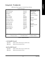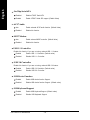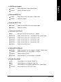
1
GA-7VASFS-FS AMD Socket A Processor Motherboard USER'S MANUAL Pentium®4 Processor Motherboard Rev. 0201 12ME-7VASFS-0201 English Table of Content Item Checklist .......................................................................................... 4 Chapter 1 Introduction ............................................................................. 5 Features Summary ....................................................................................... 5 GA-7VASFS-FS Motherboard Layout ........................................................... 7 Block Diagram .............................................................................................. 8 Chapter 2 Hardware Installation Process .............................................. 10 Step 1: Install the Central Processing Unit (CPU) ...................................... 11 Step1-1: CPU Speed Setup ............................................................................................... 11 Step1-2: CPU Installation ................................................................................................. 12 Step1-3: CPU Heat Sink Installation ................................................................................ 13 Step 2: Install memory modules ................................................................. 14 Step 3: Install expansion cards .................................................................. 16 Step 4: Connect ribbon cables, cabinet wires, and power supply .............. 17 Step 4-1: I/O Back Panel Introduction .............................................................................. 17 Step 4-2: Connectors & Jumper Setting Introduction ....................................................... 19 Chapter 3 BIOS Setup ..........................................................................31 The Main Menu (For example: BIOS Ver. : D5) .......................................... 32 Standard CMOS Features .......................................................................... 34 Advanced BIOS Features ........................................................................... 37 Integrated Peripherals ............................................................................... 39 Power Management Setup ......................................................................... 42 GA-7VASFS-FS Motherboard -2- PC Health Status ........................................................................................ 45 Frequency/Voltage Control ......................................................................... 46 Load Fail-Safe Defaults .............................................................................. 47 Load Optimized Defaults ............................................................................ 48 Set Supervisor/User Password .................................................................. 49 Save & Exit Setup ...................................................................................... 50 Exit Without Saving ................................................................................... 51 -3- Table of Content English PnP/PCI Configurations ............................................................................. 44 English Computer motherboards and expansion cards contain very delicate Integrated Circuit (IC) chips. To protect them against damage from static electricity, you should follow some precautions whenever you work on your computer. 1. Unplug your computer when working on the inside. 2. Use a grounded wrist strap before handling computer components. If you do not have one, touch both of your hands to a safely grounded object or to a metal object, such as the power supply case. 3. Hold components by the edges and try not touch the IC chips, leads or connectors, or other components. 4. Place components on a grounded antistatic pad or on the bag that came with the components whenever the components are separated from the system. 5. Ensure that the ATX power supply is switched off before you plug in or remove the ATX ower connector on the motherboard. Installing the motherboard to the chassis… If the motherboard has mounting holes, but they don't line up with the holes on the base and there are no slots to attach the spacers, do not become alarmed you can still attach the spacers to the mounting holes. Just cut the bottom portion of the spacers (the spacer may be a little hard to cut off, so be careful of your hands). In this way you can still attach the motherboard to the base without worrying about short circuits. Sometimes you may need to use the plastic springs to isolate the screw from the motherboard PCB surface, because the circuit wire may be near by the hole. Be careful, don't let the screw contact any printed circuit write or parts on the PCB that are near the fixing hole, otherwise it may damage the board or cause board malfunctioning. GA-7VASFS-FS Motherboard -4- Features Summary Form Factor CPU Chipset Memory I/O Control Slots On-Board IDE On-Board Peripherals y 30.4cm x 24.4cm ATX size form factor, 4 layers PCB. y Socket A processor AMD AthlonTM/AthlonTM XP/ DuronTM (K7) 128K L1 & 256K/64K L2 cache on die 266/333/400 MHz FSB and DDR bus speeds y Supports 1.4GHz and faster y VIA KT600 Memory/AGP/PCI Controller (PAC) y VIA VT8237 Integrated Peripheral Controller (PSIPC) y 3 184-pin DDR sockets y Supports DDR DRAM PC1600/PC2100/PC2700/PC3200<Note 2> y Supports up to 1.5GB DDR (Max) y Supports only 2.5V DDR DIMM y IT8705 y 1 AGP slot 4X (1.5V) / 8X(0.8V) device support y 5 PCI slot supports 33MHz & PCI 2.2 compliant y 2 IDE bus master (UDMA33/ATA66/ATA100) IDE ports for up to 4 ATAPI devices y Supports PIO mode3,4 (UDMA 33/ATA66/ATA100) IDE & ATAPICD-ROM y 1 Floppy port supports 2 FDD with 360K, 720K,1.2M, 1.44M and 2.88M bytes. y 1 Parallel port supports Normal/EPP/ECP mode y 1 Serial port (COMA), 1 SPDIF port, COMB on Board y 2 IEEE 1394 port y 8 USB 2.0/1.1 ports (4 x Rear, 4 xFront by cable) y 1 Front Audio Connector y 2 Serial ATA Connector to be continued...... -5- Introduction English Chapter 1 Introduction English Hardware Monitor y y y y CPU/Power/System Fan Revolution detect CPU/Power/System Fan Fail Warning CPU Overheat Warning System Voltage Detect On-Board Sound y Realtek ALC655 CODEC y Line Out / 2 front speaker y Line In / 2 rear speaker(by s/w switch) y Mic In / center& subwoofer(by s/w switch) On-Board LAN y AUX_In y Build in RTL8101L Chipset On-Board IEEE1394 PS/2 Connector y VT6307 y PS/2 Keyboard interface and PS/2 Mouse interface BIOS y Licensed AWARD BIOS y Supports Q-Flash Additional Features y PS/2 Keyboard power on by password y PS/2 Mouse power on y STR(Suspend-To-RAM) y AC Recovery y USB KB/Mouse wake up from S3 y Acoustic Management for hard drive and optical drive Please set the CPU host frequency in accordance with your processor's specifications. We don't recommend you to set the system bus frequency over the CPU's specification because these specific bus frequencies are not the standard specifications for CPU, chipset and most of the peripherals. Whether your system can run under these specific bus frequencies properly will depend on your hardware configurations, including CPU, Chipsets,SDRAM,Cards...etc. GA-7VASFS-FS Motherboard -6- English GA-7VASFS-FS Motherboard Layout KB_MS RAM_LED CPU_FAN FDD USB_1394 ATX GA-7VASFS-FS COMA SOCKET A PWR_FAN ATX_12V AUX_IN AGP DDR2 KT600 DDR3 AUDIO DDR1 F_AUDIO IDE1 USB_LAN IDE2 LPT SPDIF CODCE BAT PCI1 SW1 S_ATA1 VT8237 S_IRQ CI RTL8101L S_ATA0 CLR_CMOS PCI2 BZ PCI3 IT8705 VT6307 SYS_FAN PCI4 PWR_LED FS BIOS F_USB2 PCI5 CNR -7- F_1394 F_PANEL F_USB1 Introduction CPUCLK+/- (100/133/166MHz) AMD-K7TM AGP 2X/4X/8X System Bus100/133/166 MHz AGPCLK (66MHz) DDR RAM VIA KT600 66MHz V_Link 5 PCI HCLK+/- (100/133/166MHz) AGPCLK66MHz 33 MHz 14.318 MHz 48 MHz BIOS VIA VT8237 1394 AC97 Link Floppy IT8705 LPT Port PS/2 KB/Mouse ATA66/100/133 IDE Channels 8 USB Ports 24 MHz 33 MHz COM Port PCICLK (33MHz) USBCLK (48MHz) 14.318 MHz 33 MHz GA-7VASFS-FS Motherboard Serial ATA Channels LINE-OUT MIC PCICLK (33MHz) AC97 CODEC LINE-IN English Block Diagram CLK GEN -8- HCLK+/- (100/133/166MHz) CPUCLK+/- (100/133/166MHz) AGPCLK (66MHz) V_Link (66MHz) English -9- Introduction To set up your computer, you must complete the following steps: Step 1- Set system Switch (SW1) Step 2- Install the Central Processing Unit (CPU) Step 3- Install memory modules Step 4- Install expansion cards Step 5- Connect ribbon cables, cabinet wires, and power supply Step 4 Step 1 Step 2 Step 4 Step 4 Step 3 FS English Chapter 2 Hardware Installation Process Congratulations you have accomplished the hardware installation! Turn on the power supply or connect the power cable to the power outlet. Continue with the BIOS/ software installation. GA-7VASFS-FS Motherboard - 10 - Step1-1: CPU Speed Setup The system bus frequency can be switched at 100/133/166/200MHz by adjusting system switch FS (SW1). (The internal frequency depend on CPU.) O: ON / X :OFF 1 SW1 Default Setting: 100MHz ON SW1 CPU CLOCK 1 100MHz ON 100MHz : Fix FSB 200MHz CPU Auto : Support FSB 266/333/400 MHz CPU You must set SW1 to 100MHz when Auto OFF you used FSB 200MHz CPU. - 11 - Hardware Installation Process English Step 1: Install the Central Processing Unit (CPU) English Step1-2: CPU Installation Before installing the processor, adhere to the following warning: 1.Please make sure the CPU type is supported by the motherboard. 2.If you do not match the CPU socket Pin 1 and CPU cut edge well, it will cause improper installation. Please change the insert orientation. CPU Top View CPU Bottom View Socket Actuation Lever Pin1 indicator 2. Locate Pin 1 in the socket and look for a (golden) cut edge on the CPU 1. Pull up the CPU socket lever and up to 90-degree angle. GA-7VASFS-FS Motherboard upper corner. Then insert the CPU into the socket. - 12 - Before installing the CPU Heat Sink , adhere to the following warning: 1. Please use AMD approved cooling fan. 2. We recommend you to apply the thermal paste to provide better heat conduction between your CPU and Cooling Fan. 3. Make sure the CPU fan power cable is plugged in to the CPU fan connector, this completes the installation. Please refer to CPU cooling fan user's manual for more detail installation procedure. 2. Use qualified fan approved by AMD. 1. Press down the CPU socket lever and finish CPU installation. 3. Fasten the heatsink supporting-base 4. Make sure the CPU fan is plugged onto the CPU socket on the mainboard. to the CPU fan connector, than install complete. - 13 - Hardware Installation Process English Step1-3: CPU Heat Sink Installation Before installing the memory modules, adhere to the following warning: 1. When RAM_LED is ON, do not install / remove DIMM from socket. 2. Please note that the DIMM module can only fit in one direction due to the one notch. Wrong orientation will cause improper installation. Please change the insert orientation. The motherboard has 3 dual inline memory module(DIMM) sockets. The BIOS will automatically detects memory type and size. To install the memory module, just push it vertically into the DIMM Slot. The DIMM module can only fit in one direction due to the notch. Memory size can vary between sockets. Notch DDR FS English Step 2: Install memory modules Support Unbuffered DDR DIMM Sizes type: 64 Mbit (2Mx8x4 banks) 64 Mbit (1Mx16x4 banks) 128 Mbit(2Mx16x4 banks) 512 Mbit(16Mx8x4 banks) 256 Mbit(8Mx8x4 banks) 512 Mbit(8Mx16x4 banks) 128 Mbit(4Mx8x4 banks) 256 Mbit(4Mx16x4 banks) Only two double side DDR 400 memory modules are allowed to be used! GA-7VASFS-FS Motherboard - 14 - English 1. The DIMM slot has a notch, so the DIMM memory module can only fit in one direction. 2. Insert the DIMM memory module vertically into the DIMM slot. Then push it down. 3. Close the plastic clip at both edges of the DIMM slots to lock the DIMM module. Reverse the installation steps when you wish to remove the DIMM module. DDR Introduction Established on the existing SDRAM infrastructure, DDR (Double Data Rate) memory is a high performance and cost-effective solution that allows easy adoption for memory vendors, OEMs, and system integrators. DDR memory is a great evolutionary solution for the PC industry that builds on the existing SDRAM architecture, yet make the awesome advances in solving the system performance bottleneck by doubling the memory bandwidth. Nowadays, with the highest bandwidth of 3.2GB/s of DDR400 memory and complete line of DDR400/333/266/200 memory solutions, DDR memory is the best choice for building high performance and low latency DRAM subsystem that are suitable for servers, workstations, and full range of desktop PCs. - 15 - Hardware Installation Process English Step 3: Install expansion cards 1. Read the related expansion card's instruction document before install the expansion card into the computer. 2. Remove your computer's chassis cover, necessary screws and slot bracket from the computer. 3. Press the expansion card firmly into expansion slot in motherboard. 4. Be sure the metal contacts on the card are indeed seated in the slot. 5. Replace the screw to secure the slot bracket of the expansion card. 6. Replace your computer's chassis cover. 7. Power on the computer, if necessary, setup BIOS utility of expansion card from BIOS. 8. Install related driver from the operating system. AGP Card Please carefully pull out the small white- drawable bar at the end of the AGP slot when you try to install/ Uninstall the AGP card. Please align the AGP card to the onboard AGP slot and press firmly down on the slot .Make sure your AGP card is locked by the small whitedrawable bar. Issues To Beware Of When Installing CNR Please use standard CNR card like the one in order to avoid mechanical problem. Standard CNR Card GA-7VASFS-FS Motherboard - 16 - Step 4-1: I/O Back Panel Introduction X Z Y \ [ X PS/2 Keyboard and PS/2 Mouse Connector PS/2 Mouse Connector (6 pin Female) ¾This connector supports standard PS/2 keyboard and PS/2 mouse. PS/2 Keyboard Connector (6 pin Female) YIEEE 1394 and USB Connector ¾This connector supports IEEE 1394 and USB devices. 1394 USB 0 USB 1 ZParallel Port, Serial Port and SPDIF Port (LPT/COMA/SPDIF) Parallel Port (25 pin Female) ¾ This connector supports 1 standard COM port, 1 Parallel port and 1 SPDIF port. Device like printer can be connected to Parallel port; mouse and modem etc can be connected to Serial ports. The SPDIF output is capable of providing SPDIF Port digital audio to external speakers or com pressed AC3 data to an external Dolby Digital COMA Serial Port (9 pin Male) Decoder. Use this feature only when your stereo system has digital input function. - 17 - Hardware Installation Process English Step 4: Connect ribbon cables, cabinet wires, and power supply English [ USB & LAN Connector ¾ Before you connect your device(s) into USB connector(s), please make sure your device(s) such as USB keyboard,mouse, scanner, zip, speaker..etc. Have a standard USB interface. LAN Also make sure your OS supports USB controller. USB 0 If your OS does not support USB controller, please contact OS vendor for possible patch USB 1 or driver upgrade. For more information please contact your OS or device(s) vendors. \ Audio Connectors ¾ After install onboard audio driver, you may connect speaker to Line Out jack, micro phone Line In(Rear Speaker) to MIC In jack. Device like CD-ROM , walkman etc can be Line Out(Front Speaker) connected to Line-In jack. MIC In(Center and Subwoofer) Please note: You are able to use 2-/4-/6- channel audio feature by S/W selection. If you want to enable 6-channel function, you have 2 choose for hardware connection. Method1: Connect "Front Speaker" to "Line Out" Connect "Rear Speaker" to "Line In" Connect "Center and Subwoofer" to "MIC Out". GA-7VASFS-FS Motherboard - 18 - 1 3 English Step 4-2: Connectors & Jumper Setting Introduction 9 2 7 5 6 13 14 12 17 8 18 19 4 FS 11 10 16 1) ATX_12V 2) ATX 3) CPU_FAN 4) SYS_FAN 5) PWR_FAN 6) IDE1/IDE2 7) FDD 8) S_ATA0/S_ATA1 9) RAM_LED 10) PWR_LED 11) F_PANEL 15 12) BAT 13) F_AUDIO 14) AUX_IN 15) F_USB1/F_USB2 16) F_1394 17) S_IRQ 18) CI 19) CLR_CMOS - 19 - Hardware Installation Process This connector (ATX _12V) suppliesthe CPU operation voltage (Vcore). If this " ATX_ 12V connector" is not connected, system cannot boot. 4 1 2 Pin No. 1 2 3 4 Definition GND GND +12V +12V FS 3 2) ATX (ATX Power) AC power cord should only be connected to your power supply unit after ATX power cable and other related devices are firmly connected to the mainboard. 10 1 FS English 1) ATX_12V (+12V Power Connector) GA-7VASFS-FS Motherboard - 20 - 20 11 Pin No. 1 2 3 4 5 6 7 8 9 10 11 12 13 14 15 16 17 18 19 20 Definition 3.3V 3.3V GND VCC GND VCC GND Power Good 5V SB(stand by +5V) +12V 3.3V -12V GND PS_ON(softOn/Off) GND GND GND -5V VCC VCC Please note, a proper installation of the CPU cooler is essential to prevent the CPU from running under abnormal condition or damaged by overheating.The CPU fan connector supports Max. current up to 600 mA. Definition GND +12V Sense FS 1 Pin No. 1 2 3 4) SYS_FAN (System FAN Connector) This connector allows you to link with the cooling fan on the system case to lower the system temperature. Definition GND +12V Sense FS 1 Pin No. 1 2 3 - 21 - Hardware Installation Process English 3) CPU_FAN (CPU FAN Connector) This connector allows you to link with the cooling fan on the system case to lower the system temperature. Pin No. 1 2 3 FS 1 Definition GND +12V Sense 6) IDE1/ IDE2 (IDE1/IDE2 Connector) Please connect first harddisk to IDE1 and connect CDROM to IDE2. The red stripe of the ribbon cable must be the same side with the Pin1. 39 40 2 1 GA-7VASFS-FS Motherboard - 22 - IDE2 IDE1 FS English 5) PWR_FAN (Power Fan Connector) Please connect the floppy drive ribbon cables to FDD. It supports 360K,720K,1.2M,1.44M and 2.88Mbytes floppy disk types. The red stripe of the ribbon cable must be the same side with the Pin1. 34 1 FS 2 33 8) S_ATA0/S_ATA1 (Serial ATA Connector) You can connect the Serial ATA device to this connector, it provides you high speed transfer rates (150MB/sec).If you wish to use SATA0 and SATA1, please Enable " OnChip Serial ATA " item. Then, install the correct driver to have proper operation. For details, please refer to the "VT8237_SATA_Manual.pdf" at "http:\\www.gigabyte.com.tw" 1 Definition GND TXP TXN GND RXN RXP GND FS 7 Pin No. 1 2 3 4 5 6 7 - 23 - Hardware Installation Process English 7) FDD (Floppy Connector) Do not remove memory modules while DIMM LED is on. It might cause short or other unexpected damages due to the 2.5V stand by voltage. Remove memory modules only when AC Power cord is disconnected. + FS - 10) PWR_LED PWR_LED is connect with the system power indicator to indicate whether the system is on/off. It will blink when the system enters suspend mode. If you use dual color LED, power LED will turn to another color. 1 FS English 9) RAM_LED GA-7VASFS-FS Motherboard - 24 - Pin No. 1 2 3 Definition MPD+ MPDMPD- Please connect the power LED, PC peaker, reset switch and power switch etc of your chassis front panel to the F_PANEL connector according to the pin assignment above. Speaker Connector 20 19 SPEAKReset Switch Soft Power Connector SPEAK+ 1 PWPW+ MSGMSG+ 1 1 RES+ RESHDHD+ IDE Hard Disk Active LED FS Message LED/Power/ Sleep LED 11 2 1 NC HD (IDE Hard Disk Active LED) Pin 1: LED anode(+) (Blue) Pin 2: LED cathode(-) SPK (Speaker Connector) Pin 1: VCC(+) (Amber) Pin 2- Pin 3: NC RES (Reset Switch) Open: Normal Operation Pin 4: Data(-) (Green) Close: Reset Hardware System PW (Soft Power Connector) Open: Normal Operation (Red) Close: Power On/Off MSG(Message LED/Power/ Pin 1: LED anode(+) Sleep LED)(Yellow) Pin 2: LED cathode(-) NC( Purple) NC - 25 - Hardware Installation Process English 11) F_PANEL (2x10 pins connector) + CAUTION FS Danger of explosion if battery is incorrectly replaced. Replace only with the same or equivalent type recommended by the manufacturer. Dispose of used batteries according to the manufacturer's instructions. If you want to erase CMOS... 1.Turn OFF the computer and unplug the power cord. 2.Remove the battery, wait for 30 second. 3.Re-install the battery. 4.Plug the power cord and turn ON the computer. 13) F_AUDIO (F_AUDIO Connector) If you want to use Front Audio connector, you must remove 5-6, 9-10 Jumper. In order to utilize the front audio header, your chassis must have front audio connector. Also please make sure the pin assigment on the cable is the same as the pin assigment on the MB header. To find out if the chassis you are buying support front audio connector, please contact your dealer.Please note, you can have the alternative of using front audio connector or of using rear audio connector to play sound. FS English 12) BAT (Battery) GA-7VASFS-FS Motherboard - 26 - 10 9 2 1 Pin No. 1 2 3 4 5 6 7 8 9 10 Definition MIC GND REF POWER FrontAudio (R) RearAudio (R) Reserved No Pin FrontAudio (L) RearAudio (L) English 14) AUX_IN (AUX In Connector) Connect other device(such as PCI TV Tunner audio out)to the connector. Pin No. 1 2 3 4 FS 1 Definition AUX-L GND GND AUX_R 15) F_ USB1 / F_USB2 (Front USB Connector, Yellow) Be careful with the polarity of the front USB connector. Check the pin assignment while you connect the front USB cable. Please contact your nearest dealer for optional front USB cable. Be careful with the polarity of the F_USB connector. Check the pin assignment carefully while you connect the F_USB cable, incorrect connection between the cable and connector will make the device unable to work or even damage it. For optional F_USB cable, please contact your local dealer. 10 1 9 Definition Power Power USB DXUSB DyUSB DX+ USB Dy+ GND GND No Pin NC FS 2 Pin No. 1 2 3 4 5 6 7 8 9 10 - 27 - Hardware Installation Process Please Note: Serial interface standard set by Institute of Electrical and Electronics Engineers, which has features like high speed, high bandwidth and hot plug. 10 1 9 Definition NDCDBNSINB NSOUTB NDTRBGND NDSRBNRTSBNCTSBNRIBNo Pin FS 2 Pin No. 1 2 3 4 5 6 7 8 9 10 17) S_IRQ (Serial IRQ Connector) This connector is for special design, for example: PCMCIA add on card. 1 FS English 16) F_1394 (IEEE 1394 Connector) GA-7VASFS-FS Motherboard - 28 - Pin No. Definition 1 Signal 2 GND This 2 pin connector allows your system to enable or disable the "case open" item in BIOS if the system case begin remove. Pin No. Definition 1 Signal 2 GND FS 1 19) CLR_CMOS (Clear CMOS jumper) You may clear the CMOS data to its default values by this jumper. Default doesn’t include the "Shunter" to prevent from improper use this jumper. To Clear CMOS, temporarily short 1-2 pin. 1-2 close: Enable 1 2-3 open: Normal (Default) FS 1 - 29 - Hardware Installation Process English 18) CI (CASE OPEN) English GA-7VASFS-FS Motherboard - 30 - BIOS Setup is an overview of the BIOS Setup Program. The program that allows users to modify the basic system configuration. This type of information is stored in battery-backed CMOS RAM so that it retains the Setup information when the power is turned off. ENTERING SETUP Powering ON the computer and pressing <Del> immediately will allow you to enter Setup. If you require more advanced BIOS settings, please go to "Advanced BIOS" setting menu.To enter Advanced BIOS setting menu, press "Ctrl+F1" key on the BIOS screen. CONTROL KEYS <Ç> Move to previous item <È> Move to next item <Å> Move to the item in the left hand <Æ> Move to the item in the right hand Enter Select item <Esc> Main Menu - Quit and not save changes into CMOS Status Page Setup Menu and Option Page Setup Menu - Exit current page and return to Main Menu <+/PgUp> Increase the numeric value or make changes <-/PgDn> Decrease the numeric value or make changes <F1> General help, only for Status Page Setup Menu and Option Page Setup Menu <F2> Item Help <F3> Reserved <F4> Reserved <F5> Restore the previous CMOS value from CMOS, only for Option Page Setup Menu <F6> Load the file-safe default CMOS value from BIOS default table <F7> Load the Optimized Defaults <F8> Q-Flash function <F9> System Information <F10> Save all the CMOS changes, only for Main Menu - 31 - BIOS Setup English Chapter 3 BIOS Setup English GETTING HELP Main Menu The on-line description of the highlighted setup function is displayed at the bottom of the screen. Status Page Setup Menu / Option Page Setup Menu Press F1 to pop up a small help window that describes the appropriate keys to use and the possible selections for the highlighted item. To exit the Help Window press <Esc>. The Main Menu (For example: BIOS Ver. : D5) Once you enter Award BIOS CMOS Setup Utility, the Main Menu (Figure 1) will appear on the screen. The Main Menu allows you to select from eight setup functions and two exit choices. Use arrow keys to select among the items and press <Enter> to accept or enter the sub-menu. CMOS Setup Utility-Copyright (C) 1984-2003 Award Software Standard CMOS Features Load Fail-Safe Defaults Advanced BIOS Features Load Optimized Defaults Integrated Peripherals Set Supervisor Password Power Management Setup Set User Password PnP/PCI Configurations Save & Exit Setup PC Health Status Exit Without Saving Frequency/Voltage Control ESC:Quit :Select Item F8: Q-Flash F10:Save & Exit Setup Time, Date, Hard Disk Type... Figure 1: Main Menu If you can't find the setting you want, please press "Ctrl+F1" to search the advanced option widden. z Standard CMOS Features This setup page includes all the items in standard compatible BIOS. z Advanced BIOS Features This setup page includes all the items of Award special enhanced features. GA-7VASFS-FS Motherboard - 32 - Integrated Peripherals English z This setup page includes all onboard peripherals. z Power Management Setup This setup page includes all the items of Green function features. z PnP/PCI Configurations This setup page includes all the configurations of PCI & PnP ISA resources. z PC Health Status This setup page is the System auto detect Temperature, voltage, fan, speed. z Frequency/Voltage Control This setup page is control CPU's clock and frequency ratio. z Load Fail-Safe Defaults Fail-Safe Defaults indicates the value of the system parameters which the system would be in safe configuration. z Load Optimized Defaults Optimized Defaults indicates the value of the system parameters which the system would be in best performance configuration. z Set Supervisor password Change, set, or disable password. It allows you to limit access to the system and Setup, or just to Setup. z Set User password Change, set, or disable password. It allows you to limit access to the system. z Save & Exit Setup Save CMOS value settings to CMOS and exit setup. z Exit Without Saving Abandon all CMOS value changes and exit setup. - 33 - BIOS Setup English Standard CMOS Features CMOS Setup Utility-Copyright (C) 1984-2003 Award Software Standard CMOS Features Date (mm:dd:yy) Tue, Aug 13 2002 Item Help Time (hh:mm:ss) 22:31:24 Menu Level Change the day, month, IDE Primary Master [None] IDE Primary Slave [None] year IDE Secondary Master [None] <Week> IDE Secondary Slave [None] Sun. to Sat. Acoustic Management [Disabled] Drive A [1.44M, 3.5 in.] <Month> Drive B [None] Jan. to Dec. Floppy 3 Mode Support [Disabled] Halt On [All, But Keyboard] <Day> 1 to 31 (or maximum allowed in the month) Base Memory 640K Extended Memory 130048K <Year> Total Memory 131072K 1999 to 2098 : Move Enter:Select +/-/PU/PD:Value F5:Previous Values F10:Save ESC:Exit F6:Fail-Safe Defaults F1:General Help F7:Optimized Defaults Figure 2: Standard CMOS Features Date The date format is <week>, <month>, <day>, <year>. Week The week, from Sun to Sat, determined by the BIOS and is display only Month The month, Jan. Through Dec. Day The day, from 1 to 31 (or the maximum allowed in the month) Year The year, from 1999 through 2098 Time The times format in <hour> <minute> <second>. The time is calculated base on the 24-hour militarytime clock. For example, 1 p.m. is 13:00:00. GA-7VASFS-FS Motherboard - 34 - The category identifies the types of hard disk from drive C to F that has been installed in the computer. There are two types: auto type, and manual type. Manual type is user-definable; Auto type which will automatically detect HDD type. Note that the specifications of your drive must match with the drive table. The hard disk will not work properly if you enter improper information for this category. If you select User Type, related information will be asked to enter to the following items. Enter the information directly from the keyboard and press <Enter>. Such information should be provided in the documentation form your hard disk vendor or the system manufacturer. CYLS. Number of cylinders HEADS Number of heads PRECOMP Write precomp LANDZONE Landing zone SECTORS Number of sectors If a hard disk has not been installed select NONE and press <Enter>. Acoustic Management As well as hard disk and optical date drives such as CD-ROM, CD-RW and DVD are also responsible for generating noise in the PC. Therefore the BIOS support the acoustic management feature to reduce the noise. In the Standard CMOS Features please select the IDE drive, which should be support the Acoustic management and press Enter. When the IDE device can support the acoustic management then you can see this option in the BIOS setup. The following options are available: Hard Drive Disabled: full hard disk performance with maximum noise generation (default) Silent: lower hard disk performance with minimum noise generation Optical Drive Disabled: the device can rotate at maximum speed with maximum noise generation Medium: the device can rotate at no higher than medium speed with medium noise generation (default) Silent: the device can rotate at minimum speed only with minimum noise generation For optimal performance for hard drive and optical drive please disabled the acoustic management. Drive A / Drive B The category identifies the types of floppy disk drive A or drive B that has been installed in the computer. - 35 - BIOS Setup English IDE Primary Master, Slave / IDE Secondary Master, Slave English None No floppy drive installed 360K, 5.25 in. 5.25 inch PC-type standard drive; 360K byte capacity. 1.2M, 5.25 in. 5.25 inch AT-type high-density drive; 1.2M byte capacity (3.5 inch when 3 Mode is Enabled). 720K, 3.5 in. 3.5 inch double-sided drive; 720K byte capacity 1.44M, 3.5 in. 3.5 inch double-sided drive; 1.44M byte capacity. 2.88M, 3.5 in. 3.5 inch double-sided drive; 2.88M byte capacity. Floppy 3 Mode Support (for Japan Area) Disabled Normal Floppy Drive. (Default value) Drive A Drive A is 3 mode Floppy Drive. Drive B Drive B is 3 mode Floppy Drive. Both Drive A & B are 3 mode Floppy Drives. Halt on The category determines whether the computer will stop if an error is detected during power up. NO Errors The system boot will not stop for any error that may be detected and you will be prompted. All Errors Whenever the BIOS detects a non-fatal error the system will be stopped. All, But Keyboard The system boot will not stop for a keyboard error; it will stop for all other errors. (Default value) All, But Diskette The system boot will not stop for a disk error; it will stop for all other errors. All, But Disk/Key The system boot will not stop for a keyboard or disk error; it will stop for all other errors. Memory The category is display-only which is determined by POST (Power On Self Test) of the BIOS. GA-7VASFS-FS Motherboard - 36 - The POST of the BIOS will determine the amount of base (or conventional) memory installed in the system. The value of the base memory is typically 512 K for systems with 512 K memory installed on the motherboard, or 640 K for systems with 640 K or more memory installed on the motherboard. Extended Memory The BIOS determines how much extended memory is present during the POST. This is the amount of memory located above 1 MB in the CPU's memory address map. Advanced BIOS Features CMOS Setup Utility-Copyright (C) 1984-2003 Award Software Advanced BIOS Features First Boot Device [CDROM] Item Help Second Boot Device [Floppy] Menu Level Third Boot Device [HDD-0] Select Boot Device Password Check [Setup] priority Full Screen LOGO Show [Enabled] [Floppy] Boot from floppy [LS120] Boot from LS120 [HDD-0] Boot from First HDD [HDD-1] Boot from second HDD : Move Enter:Select F5:Previous Values +/-/PU/PD:Value F10:Save ESC:Exit F6:Fail-Safe Defaults F1:General Help F7:Optimized Defaults Figure 3: Advanced BIOS Features - 37 - BIOS Setup English Base Memory English First / Second / Third Boot Device Floppy Select your boot device priority by Floppy. LS120 Select your boot device priority by LS120. HDD-0~3 Select your boot device priority by HDD-0~3. SCSI Select your boot device priority by SCSI. CDROM Select your boot device priority by CDROM. ZIP Select your boot device priority by ZIP. USB-FDD Select your boot device priority by USB-FDD. USB-ZIP Select your boot device priority by USB-ZIP. USB-CDROM Select your boot device priority by USB-CDROM. USB-HDD Select your boot device priority by USB-HDD. LAN Select your boot device priority by LAN. Disabled Select your boot device priority by Disabled. Password Check System The system will not boot and will not access to Setup page if the correct password is not entered at the prompt. Setup The system will boot but will not access to Setup page if the correct password is not entered at the prompt. (Default value) Full Screen LOGO Show This feature allows you to show the company logo on the bootup screen. Disabled Shows the POST messages at boot. Enabled Shows the still image(LOGO) on the full screen at boot. (Default value) GA-7VASFS-FS Motherboard - 38 - English Integrated Peripherals CMOS Setup Utility-Copyright (C) 1984-2003 Award Software Integrated Peripherals OnChip IDE Channel0 [Enabled] Item Help OnChip IDE Channel1 [Enabled] Menu Level OnChip Serial ATA [Enabled] If a hard disk AC97 Audio [Auto] controller card is MC97 Modem [Auto] used, set at Disabled USB 1.1 Controller [Enabled] USB 2.0 Controller [Enabled] [Enabled] USB Device Function [Disabled] Enable on-chip IDE USB Keyboard Support [Enabled] Channel USB Mouse Support [Enabled] Onboard H/W LAN [Enabled] [Disabled] Onboard H/W 1394 [Enabled] Disable on-chip IDE Onboard Serial Port 1 [3F8/IRQ4] Channel Onboard Parallel Port [378/IRQ7] Parallel Port Mode [EPP] : Move Enter:Select F5:Previous Values +/-/PU/PD:Value F10:Save ESC:Exit F6:Fail-Safe Defaults F1:General Help F7:Optimized Defaults Figure 4: Integrated Peripherals OnChip IDE Channel0 Enabled Enable onboard channel0 IDE port. (Default value) Disabled Disable onboard channel0 IDE port. OnChip IDE Channel1 Enabled Enable onboard channel1 IDE port. (Default value) Disabled Disable onboard channel1 IDE port. - 39 - BIOS Setup English OnChip Serial ATA Disabled Disable VT8237 Serial ATA. Enabled Enable VT8237 Serial ATA support. (Default Value) AC97 Audio Auto Enable onboard AC'97 audio function. (Default Value) Disabled Disable this function. MC97 Modem Auto Enable onboard MC97 controller. (Default Value) Disabled Disable this function. USB 1.1 Controller Disable this function if you are not using onboard USB 1.1 feature. Enabled Enable USB 1.1 Controller. (Default value) Disabled Disable USB 1.1 Controller. USB 2.0 Controller Disable this function if you are not using onboard USB 2.0 feature. Enabled Enable USB 2.0 Controller. (Default value) Disabled Disable USB 2.0 Controller. USB Device Function Enabled Enable USB device function Support. Disabled Disable USB device function Support. (Default value) USB Keyboard Support Enabled Enable USB Keyboard Support. (Default value) Disabled Disable USB Keyboard Support. GA-7VASFS-FS Motherboard - 40 - Enabled Enable USB Mouse Support.(Default value) Disabled Disable USB Mouse Support. English USB Mouse Support Onboard H/W LAN Enabled Enable Onboard H/W LAN function. (Default value) Disabled Disable this function. Onboard H/W 1394 Enabled Enable onboard IEEE 1394 function.(Default value) Disabled Disable this function. Onboard Serial Port 1 Auto BIOS will automatically setup the port 1 address. 3F8/IRQ4 Enable onboard Serial port 1 and address is 3F8. (Default value) 2F8/IRQ3 Enable onboard Serial port 1 and address is 2F8. 3E8/IRQ4 Enable onboard Serial port 1 and address is 3E8. 2E8/IRQ3 Enable onboard Serial port 1 and address is 2E8. Disabled Disable onboard Serial port 1. Onboard Parallel port 378/IRQ7 Enable onboard LPT port and address is 378/IRQ7. (Default Value) 278/IRQ5 Enable onboard LPT port and address is 278/IRQ5. Disabled Disable onboard LPT port. 3BC/IRQ7 Enable onboard LPT port and address is 3BC/IRQ7. Parallel Port Mode SPP Using Parallel port as Standard Parallel Port. EPP Using Parallel port as Enhanced Parallel Port. ECP Using Parallel port as Extended Capabilities Port. (Default Value) ECP+EPP Using Parallel port as ECP & EPP mode. - 41 - BIOS Setup English Power Management Setup CMOS Setup Utility-Copyright (C) 1984-2003 Award Software Power Management Setup ACPI Suspend Type [S3(STR)] Item Help USB Device Wake-Up From S3 [Disabled] Menu Level Soft-Off by PWRBTN [Instant-Off] [S1] AC BACK Function [Memory] Set suspend type to Keyboard Power On Mouse Power On [Disabled] [Disabled] Power On Suspend under ACPI OS PME Event Wake Up [Disabled] Modem Ring Resume [Disabled] [S3] Resume by Alarm [Disabled] Set suspend type to x Date (of Month) Alarm Everyday Suspend to RAM under x Time (hh:mm:ss) 0 0 0 ACPI OS : Move Enter:Select +/-/PU/PD:Value F5:Previous Values F10:Save ESC:Exit F6:Fail-Safe Defaults F1:General Help F7:Optimized Defaults Figure 5: Power Management Setup ACPI Suspend Type S1(POS) Set ACPI suspend type to S1. S3(STR) Set ACPI suspend type to S3. (Default Value) USB Device Wake-up From S3 When set at Enabled, it allows USB Device to activate the system from ACPI S3 power saving mode. Enabled Enable USB Device Wakeup. Disabled Disable USB Device Wakeup. (Default Value) Soft-Off by PWRBTN Instant-off Press power button then Power off instantly. (Default value) Delay 4 Sec. Press power button 4 sec to Power off. Enter suspend if button is pressed less than 4 sec. GA-7VASFS-FS Motherboard - 42 - Memory System power on depends on the status before AC lost. (Default value) Soft-Off Always in Off state when AC back. Full-On Always power on the system when AC back. Keyboard Power On Password Enter from 1 to 8 characters to set the Keyboard Power On Password. Disabled Disabled this function. (Default value) Keyboard 98 If your keyboard have "POWER Key" button, you can press the key to power on your system. Mouse Power On Disabled Disabled this function. (Default value) Enabled Double click on PS/2 mouse left button to power on system. PME Event Wake Up Disabled Disable this function. (Default Value) Enabled Enable PME Event Wake up. Modem Ring Resume Disabled Disable Modem Ring Resume function. (Default Value) Enabled Enable Modem Ring Resume function. Resume by Alarm You can set "Resume by Alarm" item to enabled and key in Data/time to power on system. Disabled Disable this function. (Default Value) Enabled Enable alarm function to POWER ON system. If RTC Alarm Lead To Power On is Enabled. Date ( of Month) Alarm : Everyday, 1~31 Time ( hh: mm: ss) Alarm : (0~23) : (0~59) : (0~59) - 43 - BIOS Setup English AC BACK Function English PnP/PCI Configurations CMOS Setup Utility-Copyright (C) 1984-2003 Award Software PnP/PCI Configurations PNP OS Installed [Yes] Item Help PCI 1/PCI 5 IRQ Assignment [Auto] Menu Level PCI 2 IRQ Assignment [Auto] Select Yes if you are PCI 3 IRQ Assignment [Auto] using a Plug and Play PCI 4 IRQ Assignment [Auto] capable operating system Select No if you need the BIOS to configure non-boot devices : Move Enter:Select +/-/PU/PD:Value F5:Previous Values F10:Save ESC:Exit F6:Fail-Safe Defaults F1:General Help F7:Optimized Defaults Figure 6: PnP/PCI Configurations PNP OS Installed Yes Select Yes if you are using a Plug and Play capable operating system. (Default value) No Select No if you need the BIOS to configure non-boot devices. PCI 1/PCI 5 IRQ Assignment Auto Auto assign IRQ to PCI 1/PCI 5. (Default value) 3,4,5,7,9,10,11,12,14,15 Set IRQ 3,4,5,7,9,10,11,12,14,15 to PCI 1/PCI 5. PCI 2 IRQ Assignment Auto Auto assign IRQ to PCI 2. (Default value) 3,4,5,7,9,10,11,12,14,15 Set IRQ 3,4,5,7,9,10,11,12,14,15 to PCI 2. PCI 3 IRQ Assignment Auto Auto assign IRQ to PCI 3. (Default value) 3,4,5,7,9,10,11,12,14,15 Set IRQ 3,4,5,7,9,10,11,12,14,15 to PCI 3. PCI 4 IRQ Assignment Auto Auto assign IRQ to PCI 4. (Default value) 3,4,5,7,9,10,11,12,14,15 Set IRQ 3,4,5,7,9,10,11,12,14,15 to PCI 4. GA-7VASFS-FS Motherboard - 44 - English PC Health Status CMOS Setup Utility-Copyright (C) 1984-2003 Award Software PC Health Status Vcore 1.74V Item Help +3.3V 3.28V Menu Level +5V 5.107V +12V 11.668V 5VSB 4.919V Current System Temperature 32°C Current CPU Temperature 40°C Current CPU FAN Speed 6490 RPM Current SYSTEM FAN Speed 0 RPM Current POWER FAN Speed 0 RPM : Move Enter:Select F5:Previous Values +/-/PU/PD:Value F10:Save ESC:Exit F6:Fail-Safe Defaults F1:General Help F7:Optimized Defaults Figure 7: PC Health Status Current Voltage (V) Vcore / +3.3V / +5V / +12V /5VSB Detect system's voltage status automatically. Current System/CPU Temperature Detect System/CPU Temp. automatically. Current CPU/SYSTEM/POWER FAN Speed (RPM) Detect CPU/SYSTEM/POWER Fan speed status automatically. - 45 - BIOS Setup English Frequency/Voltage Control CMOS Setup Utility-Copyright (C) 1984-2003 Award Software Frequency/Voltage Control DRAM Clock (MHz) [Auto] Item Help Menu Level : Move Enter:Select +/-/PU/PD:Value F5:Previous Values F10:Save ESC:Exit F6:Fail-Safe Defaults F1:General Help F7:Optimized Defaults Figure 8: Frequency/Voltage Control DRAM Clock (MHz) Please set DRAM Clock according to your requirement. If you use DDR266 DRAM module, please set "DRAM Clock(MHz)" to Auto or 266. If you use DDR333 DRAM module, please set "DRAM Clock(MHz)" to Auto or 333. Incorrect using it may cause your system broken. For power End-User use only! GA-7VASFS-FS Motherboard - 46 - English Load Fail-Safe Defaults CMOS Setup Utility-Copyright (C) 1984-2003 Award Software Standard CMOS Features Load Fail-Safe Defaults Advanced BIOS Features Load Optimized Defaults Integrated Peripherals Set Supervisor Password Power Management Setup Set User Password PnP/PCI Configurations Save & Exit Setup PC Health Status Load Fail-Safe Defaults? Exit(Y/N)?Y Without Saving Frequency/Voltage Control ESC:Quit F8: Q-Flash :Select Item F10:Save & Exit Setup Load Fail-Safe Defaults Figure 9: Load Fail-Safe Defaults Load Fail-Safe Defaults Fail-Safe defaults contain the most appropriate values of the system parameters that allow minimum system performance. - 47 - BIOS Setup English Load Optimized Defaults CMOS Setup Utility-Copyright (C) 1984-2003 Award Software Standard CMOS Features Load Fail-Safe Defaults Advanced BIOS Features Load Optimized Defaults Integrated Peripherals Set Supervisor Password Power Management Setup Set User Password PnP/PCI Configurations Save & Exit Setup PC Health Status Exit Without Saving Load Optimized Defaults? (Y/N)?Y Frequency/Voltage Control ESC:Quit :Select Item F8: Q-Flash F10:Save & Exit Setup Load Optimized Defaults Figure 10: Load Optimized Defaults Load Optimized Defaults Selecting this field loads the factory defaults for BIOS and Chipset Features which the system automatically detects. GA-7VASFS-FS Motherboard - 48 - English Set Supervisor/User Password CMOS Setup Utility-Copyright (C) 1984-2003 Award Software Standard CMOS Features Load Fail-Safe Defaults Advanced BIOS Features Load Optimized Defaults Integrated Peripherals Set Supervisor Password Power Management Setup Set User Password PnP/PCI Configurations Save & Exit Setup PC Health Status Exit Without Saving Enter Password: Frequency/Voltage Control ESC:Quit F8: Q-Flash :Select Item F10:Save & Exit Setup Change/Set/Disable Password Figure 11: Password Setting When you select this function, the following message will appear at the center of the screen to assist you in creating a password. Type the password, up to eight characters, and press <Enter>. You will be asked to confirm the password. Type the password again and press <Enter>. You may also press <Esc> to abort the selection and not enter a password. To disable password, just press <Enter> when you are prompted to enter password. A message "PASSWORD DISABLED" will appear to confirm the password being disabled. Once the password is disabled, the system will boot and you can enter Setup freely. The BIOS Setup program allows you to specify two separate passwords: SUPERVISOR PASSWORD and a USER PASSWORD. When disabled, anyone may access all BIOS Setup program function. When enabled, the Supervisor password is required for entering the BIOS Setup program and having full configuration fields, the User password is required to access only basic items. If you select "System" at "Password Check" in Advance BIOS Features Menu, you will be prompted for the password every time the system is rebooted or any time you try to enter Setup Menu. If you select "Setup" at "Password Check" in Advance BIOS Features Menu, you will be prompted only when you try to enter Setup. - 49 - BIOS Setup English Save & Exit Setup CMOS Setup Utility-Copyright (C) 1984-2003 Award Software Standard CMOS Features Load Fail-Safe Defaults Advanced BIOS Features Load Optimized Defaults Integrated Peripherals Set Supervisor Password Power Management Setup Set User Password PnP/PCI Configurations & Exit Save to CMOS and EXITSave (Y/N)? Y Setup PC Health Status Exit Without Saving Frequency/Voltage Control ESC:Quit :Select Item F8: Q-Flash F10:Save & Exit Setup Save Data to CMOS Figure 12: Save & Exit Setup Type "Y" will quit the Setup Utility and save the user setup value to RTC CMOS. Type "N" will return to Setup Utility. GA-7VASFS-FS Motherboard - 50 - English Exit Without Saving CMOS Setup Utility-Copyright (C) 1984-2003 Award Software Standard CMOS Features Load Fail-Safe Defaults Advanced BIOS Features Load Optimized Defaults Integrated Peripherals Set Supervisor Password Power Management Setup Set User Password PnP/PCI Configurations Save & Exit Setup PC Health Status Exit Without Saving Quit Without Saving (Y/N)? N Frequency/Voltage Control ESC:Quit F8: Q-Flash :Select Item F10:Save & Exit Setup Abandon all Data Figure 13: Exit Without Saving Type "Y" will quit the Setup Utility without saving to RTC CMOS. Type "N" will return to Setup Utility. - 51 - BIOS Setup English GA-7VASFS-FS Motherboard - 52 -