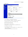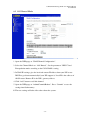
1
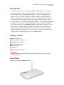
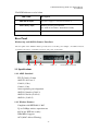
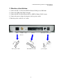
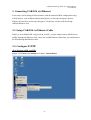
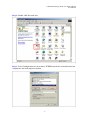
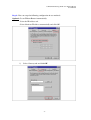
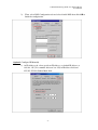
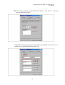
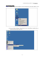
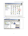
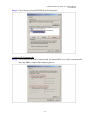
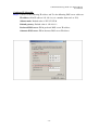
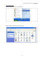
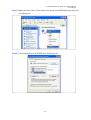
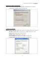
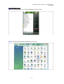
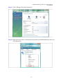
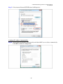
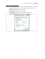
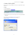
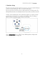
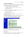
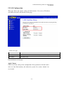
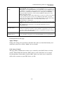
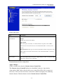
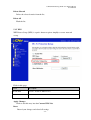
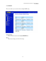
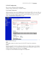
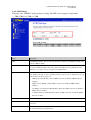
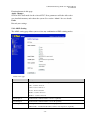
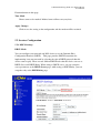
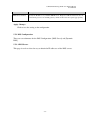
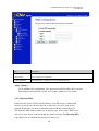
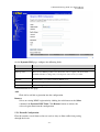
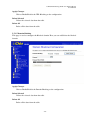
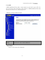
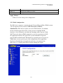
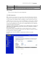
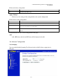
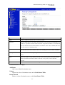
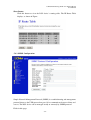
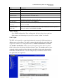
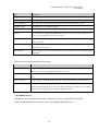
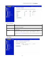
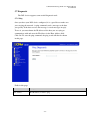
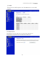
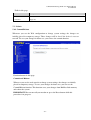
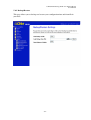
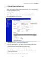
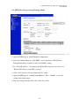
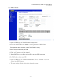
CAR-854 Wireless b/g ADSL 2/2+ Modem Router
User Manual
CAR-854
Wireless 802.11 b/g
ADSL2/2+ Modem Router
User Manual
-1-
CAR-854 Wireless b/g ADSL 2/2+ Modem Router
User Manual
Contents
1 Introduction………………………….……………………….….……..3
2 Hardware Installation………………………………………..…………5
3 Connecting CAR-854 via Ethernet…………………………….………6
3.1 Setup CAR-854 via Ethernet Cable…………………………………….…6
3.2 Configure TCP/IP…………………………………………………….…6
4 Configure CAR-854 via HTML………………………………....……22
4.1 Login……………………………………………………………...….22
5 Interface Setup……………………..…………………………..…...….23
5.1 Software Configuration…………………….………………….…..……24
5.2 LAN Configuration…………………….………………….……………25
5.2 Wireless Configuration………………….………………….…...….……26
5.3 WAN Configuration…………………….………………………………34
5.4 Services Configuration…………………….………………….…………37
5.5 Advance Configuration…………………….……………………………51
5.6 Diagnostic………………………………..……………………………58
5.7 Admin………………….……………..……………..……………..…61
5.8 Statistics…………………….…………………..………….………….66
6 Channel Mode Configuration….…………………..…….….………….68
6.1 Bridge Mode….…………………..…….….………………….……….68
6.2 MER (Mac Encapsulating Routing) Mode….…………..…………...……. 69
6.3 PPPoE Mode….…………..…………...……………………………….70
6.4 PPPoA Mode….…………..…………...……………………………….71
6.5 1483 Routed Mode….…………..…………...………………………….72
Appendices……………....…………...…………………………………..73
-2-
CAR-854 Wireless b/g ADSL 2/2+ Modem Router
User Manual
1 Introduction
The ADSL2+ Wireless Router is a high-speed ADSL2+ Ethernet/Wireless router that is
specifically designed to connect to the Internet and to directly connect to your local area
network(LAN) via high-speed 10/100 Mbps Ethernet, or wireless LAN (WLAN). The
ADSL2+ modem is compatible with the latest ADSL standards, including ADSL2 and
ADSL2+, and supports up to 24 Mbps downstream and 1.5Mbps upstream to deliver true
broadband speed and throughput. The DSL router supports wireless 802.11b/g and the
following security protocols: WEP, WPA, WPA2, and 802.1x. To ensure fully compatibility,
the DSL device was tested with all major DSLAMs, and support standard 10/100 Mbps
Base-T Ethernet interface Auto MDI/MDIx 10/100 Switch function allowing user easily to
link to PC or other Switches/Hubs. The DSL device is an idea solution for multi-users
utilizing build-in channel mode (PPPoE/A, IPoA, IPoE), IP routing, NAT functionalities
sharing the ADSL link. The DSL device is also a perfect solution for the residential users,
it supports the users with bridge mode in host based PPPoE Client.
Package Content
ADSL2+ Router * 1
Dedicated Power Adaptor * 1
RJ-45 Ethernet cable * 1
RJ-11 telephone cable * 1
Installation CD * 1
Antenna * 1
Quick Installation Guide * 1
Warning!
Only use the power adapter provided in the package, otherwise it may cause
hardware damage.
Front Panel
Wireless b/g and four port ADSL2/2+ Router
-3-
CAR-854 Wireless b/g ADSL 2/2+ Modem Router
User Manual
The LED Indicators read as below
LED NAME
Descriptions
POWER (Red light)
On: Power supply is connected and switch on.
ADSL (Orange light)
Blinking: Training with DSLAM.
On: ADSL modem links to DSLAM successfully
LAN 1-4 (Green light)
On: ADSL modem has a successful Ethernet connection.
Rear Panel
Wireless-b/g and ADSL2+ Router- Four-Port
The rear panel of the ADSL2+ Router provides access to the DC power adapter, one USB connection,
four LAN connections, one WAN connection, and power on/off switch.
WAN
ANT.
Reset
LAN 1 - 4
1.1 Specifications
1.1.1 ADSL Standard
ITU-T G.992.1(G.dmt)
ANSI T1.413 Issue 2
G.992.2 (G.lite)
G.994.1 (G.hs)
Auto-negotiating rate adaptation
ADSL2 G.dmt.bis (G.992.3)
ADSL2 G.lite.bis (G.992.4)
ADSL2+ (G.992.5)
1.1.2 Wireless Features
Compliant with IEEE 802.11 B/G
Up to 54 Mbps wireless operation rate
64/128 bits WEP for security
WPA/WPA2 support
ACL (MAC address Filtering)
-4-
Power Switch Power Jack
CAR-854 Wireless b/g ADSL 2/2+ Modem Router
User Manual
2. Hardware Installation
1. Connect the RJ-11 cable from ADSL2+ Router WAN port to DSLAM.
2. Connect the SMA from Diople Antenna.
3. Connect the RJ-45 cable from your PC to ADSL2+ Router LAN1-4 port.
4. Connect the power adapter from power jack to power outlet.
5. Push the power switch in “on” mode.
WAN
Antenna
Reset
LAN 1-4
Power Switch Power Jack
connector
RJ-11 phone cable
RJ-45 Ethernet cable
-5-
power adapter
CAR-854 Wireless b/g ADSL 2/2+ Modem Router
User Manual
3. Connecting CAR-854 via Ethernet
Your router can be managed from anywhere with the embedded Web configuration using
a Web browser, such as Microsoft Internet Explorer or Netscape Navigator. Internet
Explorer 6.0 and later or Netscape Navigator 7.0 and later versions with JavaScript
enabled should be used.
3.1. Setup CAR-854 via Ethernet Cable
If there is an available LAN card present in your PC, you just simply connect ADSL router
and PC through the Ethernet cable. Once you establish internet connection, you could browse
the Web through the Ethernet cable.
3.2. Configure TCP/IP
<For Windows 98SE and ME>
Step 1: Click Start then Settings and choose Control Panel
-6-
CAR-854 Wireless b/g ADSL 2/2+ Modem Router
User Manual
Step 2: Double click Network icon.
Step 3: Select Configuration tab, then choose TCP/IP from the list of installed network
components and click properties button.
-7-
CAR-854 Wireless b/g ADSL 2/2+ Modem Router
User Manual
Step 4: You can setup the following configuration in two methods:
Option1: Get an IP from Router Automatically
Select the IP Address tab.
Select Obtain an IP address automatically and click OK.
1)
Select Gateway tab and click OK
-8-
CAR-854 Wireless b/g ADSL 2/2+ Modem Router
User Manual
2)
Then, select DNS Configuration tab and select disable DNS then click OK to
finish the configuration.
Option2: Configure IP Manually
1) At IP Address tab, select specify an IP address, set default IP address as
192.168.1.X (X is a number between 2 to 254) in IP address field and
255.255.255.0 in Subnet Mask field.
-9-
CAR-854 Wireless b/g ADSL 2/2+ Modem Router
User Manual
2) Select Gateway tab and add default Router IP address 192.168.1.1in the New
gateway field and click Add.
Under DNS configuration tab,select Enable DNS and add DNS values(192.168.1.1)
in DNS server search order field then click add
- 10 -
CAR-854 Wireless b/g ADSL 2/2+ Modem Router
User Manual
<For Windows 2000>
Step 1: (a) Right-click My Network Places and select Properties in the main window screen
(b) Or, go to Start / Settings / Control Panel. In the Control Panel, double-click on
Network and Dial-up Connections.
- 11 -
CAR-854 Wireless b/g ADSL 2/2+ Modem Router
User Manual
Step 2: Right-click Local Area Connection (your local network hooked up with ADSL router)
and select properties
- 12 -
CAR-854 Wireless b/g ADSL 2/2+ Modem Router
User Manual
Step 3: Select internet protocol(TCP/IP) then click Properties
Configure IP Automatically:
Step 4: Select Obtain an IP address automatically and Obtain DNS server address automatically
then click OK to complete IP configuring process.
- 13 -
CAR-854 Wireless b/g ADSL 2/2+ Modem Router
User Manual
Configure IP Manually:
Step 5: Select Use the following IP address and Use the following DNS server addresses.
IP address: fill in IP address 192.168.1.x(x is a number between 2 to 254)
Subnet mask: Default value is 255.255.255.0.
Default gateway: Default value is 192.168.1.1.
Preferred DNS server: Fill in preferred DNS server IP address.
Alternate DNS server: Fill in alternate DNS server IP address
- 14 -
CAR-854 Wireless b/g ADSL 2/2+ Modem Router
User Manual
<For Windows XP>
Step 1: Click Start then select Control Panel
Step 2: Double-click Network Connections icon
- 15 -
CAR-854 Wireless b/g ADSL 2/2+ Modem Router
User Manual
Step 3: Right-click Local Area Connection(local network your ADSL hooked up with) and
select Properties:
Step 4: Select Internet Protocol(TCP/IP) then click Properties:
- 16 -
CAR-854 Wireless b/g ADSL 2/2+ Modem Router
User Manual
Configure IP address Automatically:
Step 5: Select Obtain an IP address automatically and Obtain DNS server address
automatically.Click OK to finish the configuration
Configure IP Manually:
Step 6: Select Use the following IP address and Use the following DNS server addresses.
IP address: fill in IP address 192.168.1.x(x is a number between 2 to 254)
Subnet mask: Default value is 255.255.255.0.
Default gateway: Default value is 192.168.1.1.
Preferred DNS server: Fill in preferred DNS server IP address.
Alternate DNS server: Fill in alternate DNS server IP address
- 17 -
CAR-854 Wireless b/g ADSL 2/2+ Modem Router
User Manual
<For Windows Vista>
Step 1: Click Start then select Control Panel(in the Classic View)
Step 2: Double-click Network and Sharing Center icon
- 18 -
CAR-854 Wireless b/g ADSL 2/2+ Modem Router
User Manual
Step 3: Select “Manage Network Connections”
Step 4: Right-click Local Area Connection(local network your ADSL hooked up with) and
select Properties.
- 19 -
CAR-854 Wireless b/g ADSL 2/2+ Modem Router
User Manual
Step 5: Select internet Protocol(TCP/IP) then click Properties:
Configure IP address Automatically:
Step 6: Select Obtain an IP address automatically and Obtain DNS server address automatically.
Click OK to finish the configuration
- 20 -
CAR-854 Wireless b/g ADSL 2/2+ Modem Router
User Manual
Configure IP Address Manually:
Step 7: Select Use the following IP address and Use the following DNS server addresses.
IP address: fill in IP address 192.168.1.x(x is a number between 2 to 254)
Subnet mask: Default value is 255.255.255.0.
Default gateway: Default value is 192.168.1.1.
Preferred DNS server: Fill in preferred DNS server IP address.
Alternate DNS server: Fill in alternate DNS server IP address
- 21 -
CAR-854 Wireless b/g ADSL 2/2+ Modem Router
User Manual
4. Configure CAR-854 via HTML
This device supports a Web-based (HTML) GUI to allow users to configure Router setting via
Web browser.
4.1 Login
1) Launch the Web browser.
2) Enter the default IP address http://192.168.1.1
3) Entry of the username and password will be displayed. Enter the default login User Name
and Password:
Enter the Windows system and link to http://192.168.1.1.If connection is
correctly, you will see the screen like Enter your User Name and
Password: admin/admin
- 22 -
CAR-854 Wireless b/g ADSL 2/2+ Modem Router
User Manual
5. Interface Setup
The physical connections determine whether the router ports are local area network (LAN) ports
or wide area network (WAN) ports. There are two kinds of IP networks.
The local, private kind is the LAN network; the global, public kind is the WAN network. The
following illustration shows the relationship between the router and the two different networks.
A LAN is a shared communication system to which many computers are attached. A LAN is
generally limited to the immediate area, usually the same building or floor of a building. A
WAN is an outside connection to another network or to the internet.
Click an interface Setup link to set ATM VC values, ISP Encapsulation, configure multiconnection settings, and LAN configuration.
- 23 -
CAR-854 Wireless b/g ADSL 2/2+ Modem Router
User Manual
5.1 Software Configuration
The DSL device is an ADSL2+ router. When you power on the device, the system will
boot up and connect to ADSL automatically. The system provides a PVC for bridge test by
default. The default configurations for the system are listed below.
LAN IP address: 192.168.1.1, NetMask:255.255.255.0
UART setting: 115200bps, 8 bits, no parity, 1 stop bit, no flow control.
VPI/VCI for ATM: 5/35.
ADSL Line mode: Auto-detect.
User can change settings via WEB browser. The following sections describe the set up
procedures. Please set your PC’s Ethernet port as follow:
IP address: 192.168.1.XXX
NetMask:255.255.255.0
Access the Web Console:Start your web browser.
Type the Ethernet IP address of the modem/router on the address bar of the browser.
Default IP address is 192.168.1.1.
The Enter Network Password dialog box appears. Type the user name and password and
then click OK.(default user name : admin; default password : admin)
Once you have connected to ADSL2+ router. You will see the status page.
This page displays the ADSL modem/router’s current status and settings. This information
is read-only except for the PPPoE/PPPoA channel for which user can
connect/disconnect the channel on demand. Click the “Refresh” button to
update the status.
Connect / Disconnect
The two buttons take effect only when PVC is configured as PPPoE/PPPoA mode. Click
Connect/Disconnect button to connect/disconnect the PPP dial up link.
- 24 -
CAR-854 Wireless b/g ADSL 2/2+ Modem Router
User Manual
5.2 LAN Configuration
This page shows the current setting of LAN interface. You can set IP address
and subnet mask for LAN interface in this page.
Fields in this page:
Field
Description
IP Address
The IP address your LAN hosts use to identify the device’s LAN port.
Subnet Mask
LAN subnet mask.
Function buttons in this page:
Apply Changes
Click to save the setting to the configuration. New parameters will take effect
after save into flash memory and reboot the system. See section “Admin” for
save details.
- 25 -
CAR-854 Wireless b/g ADSL 2/2+ Modem Router
User Manual
5.3 Wireless Configuration
This section provides the wireless network settings for your WLAN interface. The
wireless interface enables the wireless AP function for ADSL modem.
5.3.1 Basic Setting
This page contains all of the wireless basic settings. Most users will be able to configure
the wireless portion and get it working properly using the setting on this screen.
Field
Description
Disable Wireless LAN
Check it to disable the wireless function for ADSL modem.
Interface
Band
Select the appropriate band from the list provided to correspond with your
network setting.
Mode
The selections are: AP or AP+WDS.
SSID
The Service Set Identifier (SSID) or network name. It is case sensitive and
must not exceed 32 characters, which may be any keyboard character. The
mobile wireless stations shall select the same SSID to be able to communicate
with your ADSL modem (or AP).
- 26 -
CAR-854 Wireless b/g ADSL 2/2+ Modem Router
User Manual
Fields in this page:
Channel Number
Select the appropriate channel from the list provided to correspond with your
network settings. You shall assign a different channel for each AP to avoid
signal interference.
Radio Power (mW)
The maximum output power: 15mW, 30mW or 60mW.
Function buttons in this page:
Associated Clients
Click it will show the clients currently associated with the ADSL modem.
Apply Changes
Change the settings. New parameters will take effect after save into flash memory
and reboot the system. See section “Admin” for save details.
5.3.2 Advanced Settings
This page allows advanced users who have sufficient knowledge of wireless LAN.
These setting shall not be changed unless you know exactly what will happen for the
changes you made on your DSL device.
Fields in this page:
- 27 -
CAR-854 Wireless b/g ADSL 2/2+ Modem Router
User Manual
Field
Description
Authentication Type
Open System: Open System authentication is not required to be successful while a
client may decline to authenticate with any particular other client. Shared Key:
Shared Key is only available if the WEP option is implemented. Shared Key
authentication supports authentication of clients as either a member of those who
know a shared secret key or a member of those who do not. IEEE 802.11 Shared
Key authentication accomplishes this without the need to transmit the secret key in
clear. Requiring the use of the WEP privacy mechanism.
Auto: Auto is the default authentication algorithm. It will change its
authentication type automatically to fulfill client’s requirement.
Fragment Threshold
RTS Threshold
his value should remain at its default setting of 2346. It specifies the maximum
size for a packet before data is fragmented into multiple packets. If you experience
a high packet error, you may slightly increases the “Fragment Threshold” value
within the value range of 256 2346. Setting this value too low may result in poor
network performance. Only minor modifications of this value are recommended.
This value should remain at its default setting of 2347. Should you encounter
inconsistent data flow, only minor modifications are recommended. If a network
packet is smaller than the preset “RTS threshold” size, the RTS/CTS mechanism
will not be enabled. The ADSL modem (or AP) sends Request to Send (RTS)
frames to a particular receiving station and negotiates the sending of a data frame.
After receiving an RT the wireless station responds with a Clear to Send (CTS)
frame to
acknowledge the right to begin transmission.
Beacon Interval
The Beacon Interval value indicates the frequency interval of the beacon. Enter a
value between 20 and 1024. A beacon is a packet broadcast by the ADSL modem
(or AP) to synchronize the wireless network. The default is
100.
Data Rate
The rate of data transmission should be set depending on the speed of your
wireless network. You should select from a range of transmission speeds, or you
can select Auto to have the ADSL modem (or AP) automatically use the fastest
possible data rate and enable the Auto-Fallback feature.
Auto-Fallback will negotiate the best possible connection speed between the
AP and a wireless client. The default setting is Auto.
Function buttons in this page:
Apply Changes
Change the settings. New parameters will take effect after save into flash memory and
reboot the system. See section “Admin” for save details.
- 28 -
CAR-854 Wireless b/g ADSL 2/2+ Modem Router
User Manual
5.3.3 Security
This screen allows you to setup the wireless security. Turn on WEP or WPA by using
encryption keys could prevent any unauthorized access to your WLAN.
Fields in this page:
Field
Description
Encryption
There are 4 types of security to selected. To secure your WLAN, it’s Strongly
recommended to enable this feature.
WEP: Make sure that all wireless devices on your network are using The same
encryption level and key. Click Set WEP Key button to set the encryption key.
WPA(TKIP):WPA uses Temporal Key Integrity Protocol(TKIP) for Data
encryption. TKIP utilized a stronger encryption method and incorporates Message
Integrity Code(MIC) to provide protection against hackers.
WPA2(AES):WPA2,also known as 802.11i, uses Advanced Encryption
Standard(AES) for data encryption. AES utilized a symmetric 128-bit block data
encryption.
WAP2 Mixed:The AP supports WPA(TKIP) and WPA2(AES) for data
enctyption. The actual selection of the encryption methods will depend on the
clients.
Use 802.1x
Check it to enable 802.1x authentication. This option is selectable only when the
“Encryption” is choose to either None or WEP. If the “Encryption” is WEP, you
need to further select the WEP key length to be either WEP 64bits or WEP
128bits.
Authentication
- 29 -
CAR-854 Wireless b/g ADSL 2/2+ Modem Router
User Manual
WPA Authentication
Mode
There are 2 types of authentication mode for WPA.
WPA-RADIUS: WPA RADIUS uses an external RADIUS server to perform user
authentication. To use WPA RADIUS, enter the IP address of the RADIUS server,
the RADIUS port (default is 1812) and the shared secret from the RADIUS server.
Please refer to “Authentication RADIUS Server” setting below for RADIUS
setting. The WPA algorithm is selected between TKIP and AES, please refer to
“WPA cipher Suite” below.
Pre-Shared Key: Pre-Shared Key authentication is based on a shared secret that is
known only by the parties involved. To use WPA Pre-Shared Key, select key
format and enter a password i the “Pre-Shared Key Format” and “Pre-Shared Key”
setting respectively. Please refer to “Pre-Shared Key Format” and
“Pre-Shared Key” setting below.
Pre-Shared Key Format
PassPhrase: Select this to enter the Pre-Shared Key secret as user-friendly textual
secret.
Hex (64 characters): Select this to enter the Pre-Shared Key secret as
hexadecimal secret.
Pre-Shared Key
Specify the shared secret used by this Pre-Shared Key. If the “Pre-Shared Key
Format” is specified as PassPhrase, then it indicates a passphrase of 8 to 63
bytes long; or if the “Pre-Shared Key Format” is specified as PassPhrase, then it
indicates a 64-hexadecimal number.
Authentication
RADIUS Server
If the WPA-RADIUS is selected at “WPA Authentication Mode”, the port (default
is 1812), IP address and password of external RADIUS server are specified here.
Function buttons in this page:
Apply Changes
Change the settings. New parameters will take effect after save into flash memory and
reboot the system. See section “Admin” for save details.
5.3.4 Access Control
This page allows administrator to have access control by enter MAC address of client
stations. When Enable this function, MAC address can be added into access control
list and only those clients whose wireless MAC address are in the access control list
will be able to connect to your DSL device (or AP).
- 30 -
CAR-854 Wireless b/g ADSL 2/2+ Modem Router
User Manual
Fields in this page:
Field
Description
Wireless Access
The Selections are:
Control Mode
Disable
Disable the wireless ACL feature.
Allow Listed
When this option is selected, no wireless clients except those whose MAC
addresses are in the current access control list will be able to connect (to this
device).
Deny Listed When this option is selected, all wireless clients except those whose
MAC addresses are in the current access control list will be able to connect (to
this device).
MAC Address
Enter client MAC address and press “Apply Changes” button to add client MAC
address into current access control list.
Function buttons for the setting block:
Apply Changes
Click to add this entry into the Current Access Control List.
The Current Access Control List lists the client MAC addresses. Any wireless
client with its MAC address listed in this access control list will be able to connect to
the device. You can select the entries at the Select column and apply to the following
function buttons. Function buttons for the Current Access Control List:
- 31 -
CAR-854 Wireless b/g ADSL 2/2+ Modem Router
User Manual
Delete Selected
Delete the selected entries from the list.
Delete All
Flush the list.
5.3.5 WPS
WiFi Protect Setup (WPS) is a push –button or pin to simplify to secure network
set-up.
Fields in this page:
Field
Description
Disable WPS
Check to disable the WPS function.
Self-PIN Number
PIN number.
Apply Changes
Click to add this entry into the Current WPS List.
Reset
Discard your changes and reload all settings
- 32 -
CAR-854 Wireless b/g ADSL 2/2+ Modem Router
User Manual
5.3.6 MBSSID
This screen allows you to do the wireless multiple BSSID setup
Apply Changes
Click to add this entry into the Current MBSSID List.
Reset
Discard your changes and reload all settings
- 33 -
CAR-854 Wireless b/g ADSL 2/2+ Modem Router
User Manual
5.4 WAN Configuration
There are three sub-menu for WAN configuration:
[Channel Config], [ATM Settings], and [ADSL Settings].
5.4.1 Channel Configuration
ADSL modem/router comes with 8 ATM Permanent Virtual Channels (PVCs) at the most. There are
mainly two operations for each of the PVC channels: add and modify. And there are several channel
modes to be selected for each PVC channel. For each of the channel modes, please refer to the
section – Channel Mode Configuration for details.
Function buttons in this page:
Add
Click Add to complete the channel setup and add this PVC channel into configuration.
Modify
Select an existing PVC channel by clicking the radio button at the Select column of the Current
ATM VC Table before we can modify the PVC channel. After selecting a PVC channel, we can
modify the channel configuration at this page. Click Modify
to complete the channel modification and apply to the configuration.
- 34 -
CAR-854 Wireless b/g ADSL 2/2+ Modem Router
User Manual
5.4.2 ATM Setting
The page is for ATM PVC QoS parameters setting. The DSL device supports 4 QoS mode
— UBR / CBR / nrt-VBR / rt-VBR.
Field
Description
VPI
Virtual Path Identifier. This is read-only field and is selected on the Select column in the
Current ATM VC Table.
VCI
Virtual Channel Identifier. This is read-only field and is selected on the Select column in
the Current ATM VC Table. The VCI, together with VPI, is used to identify the next
destination of a cell as it passes through to the ATM switch.
QoS
Quality of Server, a characteristic of data transmission that measures how accurately and
how quickly a message or data is transferred from a source host to a destination host over a
network. The four QoS options are
„ UBR (Unspecified Bit Rate): When UBR is selected; the SCR and MBS fields are
disabled.
„ CBR (Constant Bit Rate): When CBR is selected; the SCR and MBS fields are
disabled.
„ nrt-VBR (non-real-time Variable Bit Rate): When nrt-VBR is selected, the SCR and
MBS fields are enabled.
„ rt-VBR (real-time Variable Bit Rate): When rt-VBR is selected, the SCR and MBS
fields are enabled.
PCR
Peak Cell Rate, measured in cells/sec., is the cell rate which the source may never exceed.
SCR
Sustained Cell Rate, measured in cells/sec., is the average cell rate over the duration of the
connection.
MBS
Maximum Burst Size, a traffic parameter that specifies the maximum number of cells that
can be transmitted at the peak cell rate.
- 35 -
CAR-854 Wireless b/g ADSL 2/2+ Modem Router
User Manual
Function buttons in this page:
Apply Changes
Set new PVC OoS mode for the selected PVC. New parameters will take effect after
save into flash memory and reboot the system. See section “Admin” for save details.
Undo
Discard your settings.
5.4.3 ADSL Setting
The ADSL setting page allows you to select any combination of DSL training modes.
Fields in this page:
Field
Description
ADSL modulation
Choose preferred xdsl standard protocols.
G.lite : G.992.2 Annex A
G.dmt : G.992.1 Annex A
T1.413 : T1.413 issue #2
ADSL2 : G.992.3 Annex A
ADSL2+ : G.992.5 Annex A
AnnexL Option
Enable/Disable ADSL2/ADSL2+ Annex L capability.
AnnexM Option
Enable/Disable ADSL2/ADSL2+ Annex M capability.
ADSL Capability
“Bitswap Enable” : Enable/Disable bitswap capability.
“SRA Enable” : Enable/Disable SRA (seamless rate adaptation) capability.
- 36 -
CAR-854 Wireless b/g ADSL 2/2+ Modem Router
User Manual
Function buttons in this page:
Tone Mask
Choose tones to be masked. Masked tones will not carry any data.
Apply Changes
Click to save the setting to the configuration and the modem will be retrained.
5.5 Services Configuration
5.5.1 DHCP Settings
DHCP Mode
You can configure your network and DSL device to use the Dynamic Host
Configuration Protocol (DHCP). This page provides DHCP instructions for
implementing it on your network by selecting the role of DHCP protocol that this
device wants to play. There are two different DHCP roles that this device can act as:
DHCP Serve and DHCP Relay. When acting as DHCP server, you can setup the
server parameters at the DHCP Server page; while acting as DHCP Relay, you can
setup the relay at the DHCP Relay page.
- 37 -
CAR-854 Wireless b/g ADSL 2/2+ Modem Router
User Manual
DHCP Server
By default, the device is configured as a DHCP server, with a predefined IP address
pool of 192.168.1.64 through 192.168.1.253 (subnet mask 255.255.255.0).
Field
Description
IP Pool Range
Specify the lowest and highest addresses in the pool.
Max Lease Time
The Lease Time is the amount of time that a network user is allowed to maintain a
network connection to the device using the current dynamic IP address. At the end of the
Lease Time, the lease is either renewed or a new IP is issued by the DHCP server. The
amount of time is in units of seconds. The default value is 86400 seconds (1 day). The
value –1 stands for the infinite lease.
Domain Name
A user-friendly name that refers to the group of hosts (subnet) that will be assigned
addresses from this pool.
Apply Changes
Set new DHCP server configuration. New parameters will take effect after save
into flash memory and reboot the system. See section “Admin” for save details.
DHCP Relay Configuration
Some ISPs perform the DHCP server function for their customers’ home/small office
network. In this case, you can configure this device to act as a DHCP relay agent.
When a host on your network requests Internet access, the device contacts your ISP to
obtain the IP configuration, and then forward that information to the host. You should
set the DHCP mode after you configure the DHCP relay.
- 38 -
CAR-854 Wireless b/g ADSL 2/2+ Modem Router
User Manual
Field
Description
DHCP Server Address
Specify the IP address of your ISP’s DHCP server. Requests for IP information from your
LAN will be passed to the default gateway, which should route the request appropriately.
Apply Changes
Click to save the setting to the configuration.
5.5.2 DNS Configuration
There are two submenus for the DNS Configuration: [DNS Server] and [Dynamic
DNS]
5.5.2.1 DNS Server
This page is used to select the way to obtain the IP addresses of the DNS servers.
- 39 -
CAR-854 Wireless b/g ADSL 2/2+ Modem Router
User Manual
Field
Description
Attain DNS
Select this item if you want to use the DNS servers obtained by the WAN interface via the
Automatically
auto-configuration mechanism.
Set DNS Manually
Select this item to configure up to three DNS IP addresses.
Apply Changes
Set new DNS relay configuration. New parameters will take effect after save into
flash memory and reboot the system. See section “Admin” for save details.
5.5.2.2 Dynamic DNS
Each time your device connects to the Internet, your ISP assigns a different IP
address to your device. In order for you or other users to access your device
from the WAN-side, you need to manually track the IP that is currently used.
The Dynamic DNS features allow you to register your device with a DNS server
and access your device each time using the same host name. The Dynamic DNS
page allows you to enable/disable the Dynamic DNS feature.
- 40 -
CAR-854 Wireless b/g ADSL 2/2+ Modem Router
User Manual
On the Dynamic DNS page, configure the following fields:
Field
Description
Enable
Check this item to enable this registration account for the DNS server.
DDNS provider
There are two DDNS providers to be selected in order to register your device with:
DynDNS and TZO. A charge may occur depends on the service you select.
Hostname
Domain name to be registered with the DDNS server.
Username
User-name assigned by the DDNS service provider.
Password
Password assigned by the DDNS service provider.
Function buttons in this page:
Add
Click Add to add this registration into the configuration.
Remove
Select an existing DDNS registration by clicking the radio button at the Select
column of the Dynamic DNS Table. Click Remove button to remove the
selected registration from the configuration.
5.5.3 Firewall Configuration
Firewall contains several features that are used to deny or allow traffic from passing
through the device.
- 41 -
CAR-854 Wireless b/g ADSL 2/2+ Modem Router
User Manual
5.5.3.1 IP/Port Filtering
The IP/Port filtering feature allows you to deny/allow specific services or applications
in the forwarding path.
Field
Outgoing Default
Action
Incoming Default
Action
Description
Specify the default action on the LAN to WAN forwarding path.
Specify the default action on the WAN to LAN forwarding path.
Click to save the setting of default actions to the configuration. Fields on the
second setting block:
Field
Description
Rule Action
Deny or allow traffic when matching this rule.
Direction
Traffic forwarding direction.
Protocol
There are 3 options available: TCP, UDP and ICMP.
Src IP Address
The source IP address assigned to the traffic on which filtering is applied.
Src Subnet Mask
Subnet-mask of the source IP.
Src Port
Starting and ending source port numbers.
Dst IP Address
The destination IP address assigned to the traffic on which filtering is applied.
Dst Subnet Mask
Subnet-mask of the destination IP.
Dst Port
Starting and ending destination port numbers.
- 42 -
CAR-854 Wireless b/g ADSL 2/2+ Modem Router
User Manual
Function buttons for this second setting block:
Apply hanges
Click to save the rule entry to the configuration. Function buttons for the
Current Filter Table:
Delete elected
Delete selected filtering rules from the filter table. You can click the checkbox at
the Select column to select the filtering rule.
Delete ll
Delete all filtering rules from the filter table.
5.5.3.2 MAC Filtering
The MAC filtering feature allows you to define rules to allow or deny frames through
the device based on source MAC address, destination MAC address, and traffic
direction.
Field
Outgoing Default
Action
Incoming Default
Action
Description
Specify the default action on the LAN to WAN bridging/forwarding path.
Specify the default action on the WAN to LAN bridging/forwarding path.
- 43 -
CAR-854 Wireless b/g ADSL 2/2+ Modem Router
User Manual
Field
Description
Rule Action
Deny or allow traffic when matching this rule
Direction
Traffic bridging/forwarding direction.
Src MAC Address
The source MAC address. It must be xxxxxxxxxxxx format. Blanks can be used in the
MAC address space and are considered as don’t care.
Dst MAC Address
The destination MAC address. It must be xxxxxxxxxxxx format. Blanks can be used in the
MAC address space and are considered as don’t care.
Click to save the setting of default actions to the configuration. Fields on the
second setting block:
Apply Changes
Click to save the rule entry to the configuration. Function buttons for the
Current Filter Table:
Delete Selected
Delete selected filtering rules from the filter table. You can click the checkbox at
the Select column to select the filtering rule.
Delete All
Delete all filtering rules from the filter table.
5.5.3.3 Port Forwarding
Firewall keeps unwanted traffic from the Internet away from your LAN computers.
Add a Port Forwarding entry will create a tunnel through your firewall so that the
computers on the Internet can communicate to one of the computers on your LAN on
a single port.
- 44 -
CAR-854 Wireless b/g ADSL 2/2+ Modem Router
User Manual
Field
Description
Port Forwarding
Check this item to enable or disable the port-forwarding feature.
Protocol
There are 3 options available: TCP, UDP and Both.
Enable
Check this item to enable this entry.
Local IP Address
IP address of your local server that will be accessed by Internet.
Local Port
The destination port number that is made open for this application on the LAN-side.
Remote IP Address
The source IP address from which the incoming traffic is allowed. Leave blank for all.
Public Port
The destination port number that is made open for this application on the WAN-side
Interface
Select the WAN interface on which the port-forwarding rule is to be applied.
Apply Changes
Click to save the rule entry to the configuration. Function buttons for the
Current Port Forwarding Table:
Delete Selected
Delete the selected port forwarding rules from the forwarding table. You can
click the checkbox at the Select column to select the forwarding rule.
Delete All
Delete all forwarding rules from the forwarding table.
5.5.3.4 URL Blocking
This page is used to configure the Blocked FQDN(Such as tw.yahoo.com) and filtered
keyword.
- 45 -
CAR-854 Wireless b/g ADSL 2/2+ Modem Router
User Manual
Apply Changes
Click to Enable/Disable the URL Blocking to the configuration.
Delete Selected
Delete the selected data from the table.
Delete All
Delete all the data from the table.
5.5.3.5 Domain Blocking
This page is used to configure the Blocked domain. Here you can add/delete the blocked
domain.
Apply Changes
Click to Enable/Disable the Domain Blocking to the configuration.
Delete Selected
Delete the selected data from the table.
Delete All
Delete all the data from the table.
- 46 -
CAR-854 Wireless b/g ADSL 2/2+ Modem Router
User Manual
5.5.3.6 DMZ
A DMZ (Demilitarized Zone) allows a single computer on your LAN to expose ALL of its
ports to the Internet. Enter the IP address of that computer as a DMZ (Demilitarized Zone) host
with unrestricted Internet access. When doing this, the
DMZ host is no longer behind the firewall.
Field
Description
DMZ Host
Check this item to enable of disable the DMZ feature.
DMZ Host IP Address
IP address of the local host. This feature sets a local host to be exposed to the Internet.
Apply Changes
Click to save the setting to the configuration.
- 47 -
CAR-854 Wireless b/g ADSL 2/2+ Modem Router
User Manual
5.5.4 IGMP Proxy Configuration
Multicasting is useful when the same data needs to be sent to more than one hosts.
Using multicasting as opposed to sending the same data to the individual hosts uses less
network bandwidth. The multicast feature also enables you to receive multicast video
stream from multicast servers. IP hosts use Internet Group Management Protocol (IGMP)
to report their multicast group memberships to neighboring routers. Similarly, multicast
routers use IGMP to discover which of their hosts belong to multicast groups. This
device supports IGMP proxy that handles IGMP messages. When enabled, this device
acts as a proxy for a LAN host making requests to join and leave multicast groups, or a
multicast router sending multicast packets to multicast group on the WAN side. When a
host wishes to join a multicast group, it sends IGMP REPORT message to the device’s
IGMP downstream interface. The proxy sets up a multicast route for the interface and
host requesting the video content. It then forwards the Join to the upstream multicast
router. The multicast IP traffic will then be forwarded to the requesting host. On a leave,
the proxy removes the route and then forwards the leave to the upstream multicast router.
The IGMP Proxy page allows you to enable multicast on WAN and LAN interfaces.
The LAN interface is always served as downstream IGMP proxy, and you can configure
one of the available WAN interfaces as the upstream IGMP proxy.
Upstream: The interface that IGMP requests from hosts are sent to the multicast router.
Downstream: The interface data from the multicast router are sent to hosts in the
multicast group database.
- 48 -
CAR-854 Wireless b/g ADSL 2/2+ Modem Router
User Manual
Field
Description
IGMP Proxy
Enable/disable IGMP proxy feature
Proxy Interface
The upstream WAN interface is selected here.
Apply Changes
Click to save the setting to the configuration.
5.5.5 UPnP Configuration
The DSL device supports a control point for Universal Plug and Play (UPnP) version
1.0, and supports two key features: NAT Traversal and Device
Identification. This feature requires one active WAN interface. In addition,
the host should support this feature. In the presence of multiple WAN
interfaces, select an interface on which the incoming traffic is present. With
NAT Traversal, when an UPnP command is received to open ports in NAT,
the application translates the request into system commands to open the
ports in NAT and the firewall. The interface to open the ports on is given to
UPnP when it starts up and is part of the configuration of the application.
For Device Identification, the application will send a description of the
DSL device as a control point back to the host making the request.
- 49 -
CAR-854 Wireless b/g ADSL 2/2+ Modem Router
User Manual
Field
Description
UPnP
Enable/disable UPnP feature.
WAN Interface
Select WAN interface that will use UPnP from the drop-down lists.
Apply Changes
Click to save the setting to the system configuration.
5.5.6 RIP Configuration
RIP is an Internet protocol you can set up to share routing table information with other
routing devices on your LAN, at your ISP’s location, or on remote networks connected
to your network via the ADSL line. Most small home or office networks do not need to
use RIP; they have only one router, such as the ADSL Router, and one path to an ISP. In
these cases, there is no need to share routes, because all Internet data from the network
is sent to the same ISP gateway. You may want to configure RIP if any of the following
circumstances apply to your network:
Your home network setup includes an additional router or RIP-enabled PC (other than the
ADSL Router). The ADSL Router and the router will need to communicate via RIP to
share their routing tables.
Your network connects via the ADSL line to a remote network, such as a corporate
network. In order for your LAN to learn the routes used within your corporate network,
they should both be configured with RIP.
Your ISP requests that you run RIP for communication with devices on their
network.
- 50 -
CAR-854 Wireless b/g ADSL 2/2+ Modem Router
User Manual
Fields on the first setting block:
Field
Description
RIP
Enable/disable RIP feature.
Apply Changes
Click to save the setting of this setting block to the system configuration
Fields on the second setting block:
Field
Description
Interface
The name of the interface on which you want to enable RIP.
Receive Mode
Indicate the RIP version in which information must be passed to the DSL device in order
for it to be accepted into its routing table.
Send Mode
Indicate the RIP version this interface will use when it sends its route information to other
devices.
Function buttons for the second setting block in this page:
Add
Add a RIP entry and the new RIP entry will be display in the table
5.6 Advance Configuration
5.6.1 Bridging
You can enable/disable Spanning Tree Protocol and set MAC address aging time in
this page.
- 51 -
CAR-854 Wireless b/g ADSL 2/2+ Modem Router
User Manual
Field
Description
Ageing Time
Set the Ethernet address ageing time, in seconds. After [Ageing Time] seconds of not
having seen a frame coming from a certain address, the bridge will time out (delete) that
address from Forwarding DataBase (fdb).
802.1d Spanning Tree
Enable/disable the spanning tree protocol
Save this bridge configuration. New configuration will take effect after saving into
flash memory and rebooting the system. See section “Admin” for details.
Show MACs
List the MAC address in forwarding table.
5.6.2 Routing
The Routing page enables you to define specific route for your Internet and network
data. Most users do not need to define routes. On a typical small home or office LAN,
the existing routes that set up the default gateways for your LAN hosts and for the
DSL device provide the most appropriate path for all your Internet traffic.
On your LAN hosts, a default gateway directs all Internet traffic to the
LAN port(s) on the DSL device. Your LAN hosts know their default gateway
either because you assigned it to them when you modified your TCP/IP properties,
or because you configured them to receive the information dynamically from a
server whenever they access the Internet. On the DSL device itself, a default
gateway is defined to direct all outbound Internet traffic to a route at your ISP.
The default gateway is assigned either automatically by your ISP whenever the
device negotiates an Internet access, or manually by user to setup through the
configuration.
You may need to define routes if your home setup includes two or more networks or
subnets, if you connect to two or more ISP services, or if you connect to a remote
corporate LAN.
- 52 -
CAR-854 Wireless b/g ADSL 2/2+ Modem Router
User Manual
Field
Description
Enable
Check to enable the selected route or route to be added.
Destination
The network IP address of the subnet. The destination can be specified as the IP address of
a subnet or a specific host in the subnet. It can also be specified as all zeros to indicate that
this route should be used for all destinations for which no other route is defined (this is the
route that creates the default gateway).
Subnet Mask
Next Hop
The network mask of the destination subnet. The default gateway uses a mask of 0.0.0.0.
The IP address of the next hop through which traffic will flow towards the destination
subnet.
Metric
Defines the number of hops between network nodes that data packets travel. The default
value is 0, which means that the subnet is directly one hop away on the local LAN
network.
Interface
The WAN interface to which a static routing subnet is to be applied.
Function buttons in this page:
Add Route
Add a user-defined destination route.
Update
Update the selected destination route on the Static Route Table.
Delete Selected
Delete a selected destination route on the Static Route Table.
- 53 -
CAR-854 Wireless b/g ADSL 2/2+ Modem Router
User Manual
Show Routes
Click this button to view the DSL device’s routing table. The IP Route Table
displays, as shown in Figure.
5.6.3 SNMP Configuration
Simple Network Management Protocol (SNMP) is a troubleshooting and management
protocol that uses the UDP protocol on port 161 to communicate between clients and
servers. The DSL device can be managed locally or remotely by SNMP protocol.
Fields in this page:
- 54 -
CAR-854 Wireless b/g ADSL 2/2+ Modem Router
User Manual
Field
Description
System Description
System description of the DSL device.
System Contact
Contact person and/or contact information for the DSL device.
System Name
An administratively assigned name for the DSL device.
System Location
The physical location of the DSL device.
System Object ID
Vendor object identifier. The vendor’s authoritative identification of the network
management subsystem contained in the entity.
Trap IP Address
Destination IP address of the SNMP trap.
Community name
Name of the read-only community. This read-only community allows read operation to all
(read-only)
objects in the MIB.
Community name
Name of the read-only community. This write-only community allows write operation to
(write-only)
the objects defines as read-writable in the MIB.
Apply Changes
Save SNMP configuration. New configuration will take effect after saving into
flash memory and rebooting the system. See section “Admin” for details.
5.6.4 IP QoS
The DSL device provides a control mechanism that can provide different priority to
different users or data flows. The QoS is enforced by the QoS rules in the QoS table.
A QoS rule contains two configuration blocks: Traffic Classification and Action.
The Traffic Classification enables you to classify packets on the basis of various
fields in the packet and perhaps the physical ingress port. The Action enables you to
assign the strictly priority level for and mark some fields in the packet that matches
the Traffic Classification rule. You can configure any or all field as needed in these
two QoS blocks for a QoS rule.
- 55 -
CAR-854 Wireless b/g ADSL 2/2+ Modem Router
User Manual
Field
Description
IP QoS
Enable/disable the IP QoS function.
Source IP
The IP address of the traffic source.
Source Netmask
The source IP netmask. This field is required if the source IP has been entered.
Destination IP
The IP address of the traffic destination.
Destination Netmask
The destination IP netmask. This field is required if the destination IP has been entered.
Protocol
The selections are TCP, UDP, ICMP and the blank for none. This field is required if the
source port or destination port has been entered.
Source Port
The source port of the selected protocol. You cannot configure this field without entering
the protocol first.
Destination Port
The destination port of the selected protocol. You cannot configure this field without
entering the protocol first.
Physical Port
The incoming ports. The selections include LAN ports, wireless port, and the blank for not
applicable.
Fields on the second setting block of this page:
Field
Description
Outbound Priority
The priority level for the traffic that matches this classification rule. The possible
selections are (in the descending priority): p0, p1, p2, p3.
IP Precedence
Select this field to mark the IP precedence bits in the packet that match this classification
rule.
IP Type of Service
Select this field to mark the IP TOS bits in the packet that match this classification rule.
802.1p
Select this field to mark the 3-bit user-priority field in the 802.1p header of the packet that
match this classification rule. Note that this 802.1p marking is workable on a given PVC
channel only if the VLAN tag is enabled in this PVC channel.
5.6.5 Remote Access
The Remote Access function can secure remote host access to your DSL device from
LAN and WLAN interfaces for some services provided by the DSL device.
- 56 -
CAR-854 Wireless b/g ADSL 2/2+ Modem Router
User Manual
Fields in this page:
Field
Description
LAN
Check/un-check the services on the LAN column to allow/un-allow the services access
WAN
from LAN side; and “WAN”:
Check/un-check the services on the WAN column to allow/un-allow the services access
WAN Port
from WAN side.
This field allows the user to specify the port of the corresponding service. Take the
HTTP service for example; when it is changed to 8080, the HTTP server address for the
WAN side is http://dsl_addr:8080, where the dsl_addr is the WAN side IP address of the
DSL
5.6.6 Others
- 57 -
CAR-854 Wireless b/g ADSL 2/2+ Modem Router
User Manual
5.7 Diagnostic
The DSL device supports some useful diagnostic tools.
5.7.1 Ping
Once you have your DSL device configured, it is a good idea to make sure
you can ping the network. A ping command sends a message to the host
you specify. If the host receives the message, it sends messages in reply.
To use it, you must know the IP address of the host you are trying to
communicate with and enter the IP address in the Host Address field.
Click Go! To start the ping command, the ping result will then be shown
in this page.
Fields in this page:
Field
Description
Host Address
The IP address you want to ping.
- 58 -
CAR-854 Wireless b/g ADSL 2/2+ Modem Router
User Manual
5.7.2 ATM Loopback
In order to isolate the ATM interface problems, you can use ATM OAM
loopback cells to verify connectivity between VP/VC endpoints, as well
as segment endpoints within the VP/VC. ATM uses F4 and F5 cell
flows as follows:
F4: used in VPs
F5: used in VCs
An ATM connection consists of a group of points. This OAM
implementation provides management for the following points:
Connection endpoint: the end of a VP/VC connection where the ATM
cell are terminated
Segment endpoint: the end of a connection segment
This page allows you to use ATM ping, which generates F5 segment and
end-to-end loop-back cells to test the reach ability of a segment endpoint
or a connection endpoint.
Fields in this page:
Field
Description
Select PVC
Select the PVC channel you want to do the loop-back diagnostic.
Flow Type
The ATM OAM flow type. The selection can be F5 Segment or F5 End-to-End.
Loopback Location ID
The loop-back location ID field of the loop-back cell. The default value is all 1s (ones) to
indicate the endpoint of the segment or connection.
- 59 -
CAR-854 Wireless b/g ADSL 2/2+ Modem Router
User Manual
5.7.3 ADSL
This page shows the ADSL diagnostic result. Click Start button to start the ADSL
diagnostic.
5.7.4 Diagnostic Test
The Diagnostic Test page shows the test results for the connectivity of
the physical layer and protocol layer for both LAN and WAN sides.
- 60 -
CAR-854 Wireless b/g ADSL 2/2+ Modem Router
User Manual
Fields in this page:
Field
Description
Select the Internet
The available WAN side interfaces are listed. You have to select one for the WAN side
Connection
diagnostic.
5.8 Admin
5.8.1 Commit/Reboot
Whenever you use the Web configuration to change system settings, the changes are
initially placed in temporary storage. These changes will be lost if the device is reset or
turn off. To save your change for future use, you can use the commit function.
Function buttons in this page:
Commit and Reboot
Whenever you use the web console to change system settings, the changes are initially
placed in temporary storage. To save your changes for future use, you can use the
Commit/Reboot function. This function saves your changes from RAM to flash memory
and reboot the system.
IMPORTANT! Do not turn off your modem or press the Reset button while this
procedure is in progress.
- 61 -
CAR-854 Wireless b/g ADSL 2/2+ Modem Router
User Manual
5.8.2 Backup/Restore
This page allows you to backup and restore your configuration into and from file in
your host.
- 62 -
CAR-854 Wireless b/g ADSL 2/2+ Modem Router
User Manual
5.8.3 Password
The first time you log into the system, you use the default password. There are two-level
logins: admin and system. The admin and system password configuration allows you
to change the password for administrator and user.
Fields in this page:
Field
Description
User Name
Selection of user levels are: admin and user.
Old Password
Enter the old password for this selected login.
New Password
Enter the new password here.
Confirmed Password
Enter the new password here again to confirm.
5.8.4 Upgrade Firmware
To upgrade the firmware for the DSL device:
Click the Browse button to select the firmware file.
Confirm your selection.
Click the Upload button to start upgrading.
IMPORTANT! Do not turn off your DSL device or press the Reset button
while this procedure is in progress.
- 63 -
CAR-854 Wireless b/g ADSL 2/2+ Modem Router
User Manual
5.8.5 ACL Config
The Access Control List (ACL) is a list of permissions attached to the DSL
device. The list specifies who is allowed to access this device. If ACL is
enabled, all hosts cannot access this device except for the hosts with IP
address in the ACL table.
Fields in this page:
Field
Description
ACL Capability
Enable/disable the ACL function
Enable
Check to enable this ACL entry
Interface
Select the interface domain: LAN or WAN
IP Address
Enter the IP address that allows access to this device.
- 64 -
CAR-854 Wireless b/g ADSL 2/2+ Modem Router
User Manual
5.8.6 Time Zone
Simple Network Timing Protocol (SNTP) is a protocol used to
synchronize the system time to the public SNTP servers. The DSL
device supports SNTP client functionality in compliance with IETF
RFC2030. SNTP client functioning in daemon mode which issues
sending client requests to the configured SNTP server addresses
periodically can configure the system clock in the DSL device
Field
Description
Current Time
The current time of the specified time zone. You can set the current time by yourself or
configured by SNTP.
Time Zone Select
The time zone in which the DSL device resides.
Enable SNTP client
Enable the SNTP client to update the system clock.
update
SNTP server
The IP address or the host name of the SNTP server. You can select from the list or set it
manually.
- 65 -
CAR-854 Wireless b/g ADSL 2/2+ Modem Router
User Manual
5.9 Statistics
The DSL device shows the different layer of network statistics information.
5.9.1 Interfaces
You can view statistics on the processing of IP packets on the networking interfaces.
You will not typically need to view this data, but you may find it helpful when working
with your ISP to diagnose network and Internet data transmission problems.
To display updated statistics showing any new data since you opened this page, click
Refresh.
- 66 -
CAR-854 Wireless b/g ADSL 2/2+ Modem Router
User Manual
5.9.2 ADSL
This page shows the ADSL line statistic information.
- 67 -
CAR-854 Wireless b/g ADSL 2/2+ Modem Router
User Manual
6. Channel Mode Configuration
ADSL router supports multiple channel operation modes. This section will show
procedures to configure the router.
6.1 Bridge Mode
ADSL modem/router is bridge mode enabled by factory default. There is a
1483-bridged mode PVC 5/35 in system.
1 Open the WEB page at “WAN/Channel Configuration”.
2 Select the Channel Mode to “1483 Bridged”. Set the parameters VPI/VCI and
Encapsulation mode according to the CO DSLAM’s setting.
3 Click “Add” button to add this channel into VC table.
4 Open the WEB page at “Admin/Commit/Reboot”. Press “Commit” to save the
settings into flash memory.
5 The new settings will take effect after reboot the system.
- 68 -
CAR-854 Wireless b/g ADSL 2/2+ Modem Router
User Manual
6.2 MER(Mac Encapsulating Routing) Mode
1 Open the WEB page at “WAN/Channel Configuration”.
2 Select the Channel Mode to “1483 MER”. Set the parameters VPI/VCI and
Encapsulation mode according to the CO DSLAM’s setting.
3 Set “Local IP Address:” according to the IP that ISP assign for your router. Set
“Remote IP Address” to the ISP’s gateway.
4 Click “Add” button to add this channel into VC table.
5 Open the WEB page at “Admin/Commit/Reboot”. Press “Commit” to save the
settings into flash memory.
6 The new settings will take effect after reboot the system.
- 69 -
CAR-854 Wireless b/g ADSL 2/2+ Modem Router
User Manual
6.3 PPPoE Mode
1 Open the WEB page at “WAN/Channel Configuration”.
2 Select the Channel Mode to “PPPoE”. Set the parameters VPI/VCI and
Encapsulation mode according to the CO DSLAM’s setting.
3 Enter user/password from your ISP.
4 Click “Add” button to add this channel.
5. Enable DHCP server to allow the local PCs share the PPP connection.
6. Set DNS address from your ISP.
7. Open the WEB page at “Admin/Commit/Reboot”. Press “Commit” to save the
settings into flash memory.
8. The new settings will take effect after reboot the system.
- 70 -
CAR-854 Wireless b/g ADSL 2/2+ Modem Router
User Manual
6.4 PPPoA Mode
1 Open the WEB page at “WAN/Channel Configuration”.
2 Select the Channel Mode to “PPPoA”. Set the parameters VPI/VCI and
Encapsulation mode according to the CO DSLAM’s setting.
3 Enter user/password from your ISP.
4 Click “Add” button to add this channel.
5. Enable DHCP server to allow the local PCs share the PPP connection.
6. Set DNS address from your ISP.
7. Open the WEB page at “Admin/Commit/Reboot”. Press “Commit” to save the
settings into flash memory.
8. The new settings will take effect after reboot the system.
- 71 -
CAR-854 Wireless b/g ADSL 2/2+ Modem Router
User Manual
6.5 1483 Routed Mode
1 Open the WEB page at “WAN/Channel Configuration”.
2 Select the Channel Mode to “1483 Routed”. Set the parameters VPI/VCI and
Encapsulation mode according to the CO DSLAM’s setting.
3 In WAN IP settings, give the local and remote IP address from your ISP or use
DHCP to get them automatically if your ISP support it. Local IP is the address of
ADSL router. Remote IP is the ISP’s gateway address.
4 Click “Add” button to add this channel.
5 Open the WEB page at “Admin/Commit/Reboot”. Press “Commit” to save the
settings into flash memory.
6 The new settings will take effect after reboot the system.
- 72 -
CAR-854 Wireless b/g ADSL 2/2+ Modem Router
User Manual
Appendices
Appendix A: Protocol Stacks
6.5.1 A.1 1483 Bridged Model
PC
ATU-R
DSLAM
1483 Bridged Channel Mode Scenario
- 73 -
BRAS
CAR-854 Wireless b/g ADSL 2/2+ Modem Router
User Manual
6.5.2 A.2 1483 MER Model
PC
ATU-R
DSLAM
1483 MER Channel Mode Scenario
- 74 -
BRAS
CAR-854 Wireless b/g ADSL 2/2+ Modem Router
User Manual
6.5.3 A.3 PPPoE Model
PC
ATU-R
DSLAM
PPPoE Channel Mode Scenario
- 75 -
BRAS
CAR-854 Wireless b/g ADSL 2/2+ Modem Router
User Manual
6.5.4 A.4 PPPoA Model
PC
ATU-R
DSLAM
PPPoA Channel Mode Scenario
- 76 -
BRAS
CAR-854 Wireless b/g ADSL 2/2+ Modem Router
User Manual
6.5.5 A.5 1483 Routed Model
PC
ATU-R
DSLAM
1483 Routed Channel Mode Scenario
- 77 -
BRAS