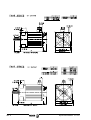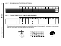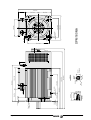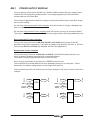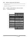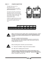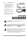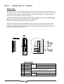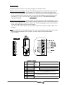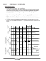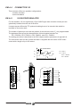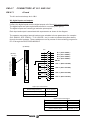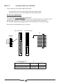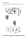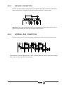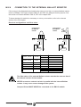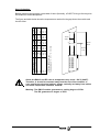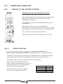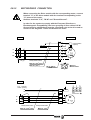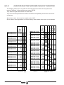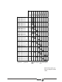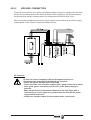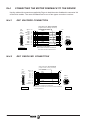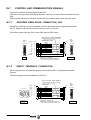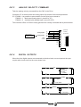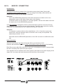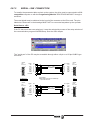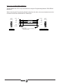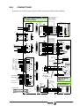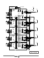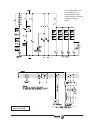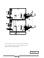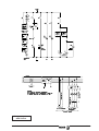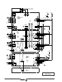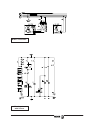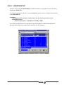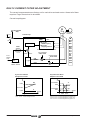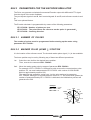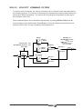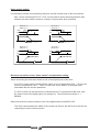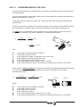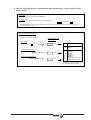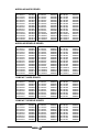
1
SERVO-DRIVESYSTEM General Manual Ver. 0002 (ing) Title Type of documentation Internal code Model Version Software Electronic document Headquarters Servo-Drive System Description, Installation and setup of motors and digital drives. 04754001 MAN REGUL (IN) 0002 Version 04.01 D_DDS.pdf FAGOR AUTOMATION S.COOP. Bº San Andrés s/n, Apdo. 144 E-20500 ARRASATE-MONDRAGON www.fagorautomation.mcc.es [email protected] Service Dept. Telephone 34-943-771118 The information described in this manual may be subject to changes due to technical modifications.FAGOR AUTOMATION, S. Coop. reserves the right to change the contents of this manual without prior notice. Evolution Version items 9702 First version 9707 PS-65, RM-15, CM-60, APS24, AXD3.., y SPD3.. PowerPro 110A, new motors FXM. 9802 Compact 8,25, 50,75, DDS PROGRAM MOD. Software 02.xx: Halt signal via digital input. Range expansion, (C axis) SERCOS interface. (connection and parameters) 9810 Software 03.xx: Sincoder feedback (E1). Motor identification at the encoder. Description of the XPS. Emergency ramps. Current filter. Sercos interface (servo system adjustment). Expansion of parameters for gear ratios. Communications with the PLC. Overload detection. Spindles at low rpm. 9904 Software 03.03: New fanned motors FXM. New SPM 180M motor. New products (Mains voltage 460 Vac). Full motor identification. Description and installation of the XPS. New drive AXD/SPD 1.35. EMK. filters. Drive off delay time, GP9. 0002 SPMxx.1 Motors Absolut encoder A1 PS-25B Improved AXD/SPD 1.15. Resistences ER. Digital I/O boards. Software 04.01: Current filter. Position Loop: Feedforward, Homing, Backlash compensation, Following error control, Modulo Format. Direct feedback. Selection RELATED DOCUMENTATION Fagor Motors and Drives Ordering Handbook Description Installation an setup This is your document. Servo Drive System Code: 04754001 Quick Reference Fagor Motion Control Code: 04xxxxxx Fagor Modular Drives and Motors Quick Reference Code: 14460010 Sistema de Regulación Code: 04754000 Fagor Motion Control Code: 04xxxxxx Fagor Compact Drives and Motors Quick Reference Code: 14460012 General Index pg. SM. SM.1 SM.2 SM.3 SM.4 SM.5 SM.5.1 SM.5.2 SM.5.2.1 SM.5.2.2 SM.6 SM.7 SM.8 SM.9 AM. AM.1 AM.2 AM.3 AM.4 AM.5 AM.6 AM.7 AM.8 AM.8.1 AM.8.2 AM.8.3 AM.9 AM.9.1 AM.9.2 AM.9.3 AM.10 AM.10.1 AM.10.2 AM.10.3 AM.10.4 AM.10.5 AM.11 AM.12 AM.13 AM.13.1 AM.14 AM.15 EM. EM.1 EM.1.1 EM.1.2 EM.1.3 EM.1.3.1 EM.1.3.2 EM.1.3.3 EM.1.3.4 FXM SERIES SYNCHRONOUS MOTORS ........................................................... SM - 1 GENERAL CHARACTERISTICS .................................................................................... SM - 2 ELECTRICAL CHARACTERISTICS ................................................................................ SM - 3 DIMENSIONS .............................................................................................................. SM - 7 BRAKE CHARACTERISTICS ....................................................................................... SM - 12 CONNECTORS ........................................................................................................... SM - 12 POWER AND BRAKE CONNECTOR ......................................................................... SM - 12 FEEDBACK CONNECTOR ........................................................................................ SM - 13 ENCODER FEEDBACK CONNECTOR ..................................................................... SM - 13 RESOLVER FEEDBACK CONNECTOR .................................................................... SM - 14 INSTALLATION AND MOUNTING CONDITIONS ............................................................. SM - 15 RADIAL AND AXIAL LOADS ........................................................................................ SM - 15 IDENTIFICATION BOARD ............................................................................................ SM - 16 REGISTRATION NUMBERS FOR FXM MOTORS .......................................................... SM - 16 SPM ASYNCHRONOUS MOTORS ........................................................................ AM - 1 GENERAL CHARACTERISTICS .................................................................................... AM - 1 ELECTRICAL CHARACTERISTICS ............................................................................... AM - 2 FAN CHARACTERISTICS ............................................................................................. AM - 3 BRAKE CHARACTERISTICS (OPTIONAL) ..................................................................... AM - 4 CHARACTERISTICS OF THE ROLLER BEARINGS ........................................................ AM - 4 POWER AND TORQUE CHARACTERISTICS ................................................................. AM - 5 DIMENSIONS ............................................................................................................. AM - 12 CONNECTORS ........................................................................................................... AM - 22 POWER AND BRAKE CONNECTION ......................................................................... AM - 22 FEEDBACK CONNECTION. ENCODER ..................................................................... AM - 23 FAN CONNECTION ................................................................................................... AM - 23 INSTALLING RECOMMENDATIONS ............................................................................. AM - 24 VENTILATION ........................................................................................................... AM - 25 MOUNTING OPTIONS ............................................................................................... AM - 25 AMBIENT CONDITIONS ............................................................................................ AM - 26 COUPLING ................................................................................................................. AM - 26 DIRECT COUPLING .................................................................................................. AM - 26 COUPLING THROUGH TRANSMISSION PULLEYS ..................................................... AM - 26 COUPLING THROUGH GEAR BOXES ....................................................................... AM - 27 BALANCING ............................................................................................................. AM - 27 MOUNTING THE GEAR BOXES ................................................................................. AM - 27 RADIAL AND AXIAL LOADS ........................................................................................ AM - 27 BEARINGS ................................................................................................................ AM - 28 MAINTENANCE INTERVALS ....................................................................................... AM - 29 BEARING REPLACEMENT ....................................................................................... AM - 29 IDENTIFICATION BOARD ............................................................................................ AM - 30 REGISTRATION NUMBERS FOR SPM MOTORS .......................................................... AM - 30 ELECTRONIC MODULES ...................................................................................... EM - 1 POWER SUPPLY MODULE ......................................................................................... EM - 5 GENERAL CHARACTERISTICS OF THE NON-REGENERATIVE POWER SUPPLIES ..... EM - 6 GENERAL CHARACTERISTICS OF THE REGENERATIVE POWER SUPPLIES ............. EM - 8 POWER SUPPLY CONNECTORS .............................................................................. EM - 9 POWER CONNECTORS OF THE POWER SUPPLIES .............................................. EM - 11 X1 CONNECTOR, INTERNAL BUS ........................................................................... EM - 14 X2 CONNECTOR, CONTROL ................................................................................... EM - 14 CONNECTORS X3, X4, X5, X6 (XPS AND PS-25B) ..................................................... EM - 16 EM.2 EM.2.1 EM.2.1.1 EM.2.2 EM.2.3 EM.2.3.1 EM.3 EM.3.1 EM.3.2 EM.3.3 EM.3.3.1 EM.3.3.2 EM.4 EM.4.1 EM.4.2 EM.4.3 EM.4.3.1 EM.4.4 EM.4.4.1 EM.4.4.2 EM.4.5 EM.4.6 EM.4.7 EM.4.7.1 EM.4.7.2 EM.4.7.3 EM.4.8 EM.5 EM.6 EM.7 EM.8 EM.9 EM.9.1 EM.10 EM.11 EM.12 EM.13 IN. IN.1 IN.1.1 IN.2 IN.2.1 IN.2.2 IN.2.3 IN.2.4 IN.3 IN.3.1 IN.3.1.1 IN.3.1.2 IN.3.1.3 IN.3.1.4 IN.3.1.5 IN.3.1.6 IN.3.2 IN.3.2.1 IN.3.3 IN.4 IN.4.1 MODULAR DRIVE (AXES AND SPINDLE) ................................................................... EM GENERAL CHARACTERISTICS, MODULAR DRIVES .................................................. EM AXIS AND SPINDLE DRIVES ................................................................................... EM DERATING OF THE MODULAR DRIVES ..................................................................... EM CONNECTORS OF THE MODULAR DRIVE ................................................................ EM POWER CONNECTORS ......................................................................................... EM COMPACT DRIVE (AXES AND SPINDLE) ..................................................................... EM GENERAL CHARACTERISTICS ................................................................................ EM DERATING, COMPACT DRIVES ................................................................................. EM CONNECTORS OF THE COMPACT DRIVE ................................................................. EM POWER CONNECTORS ......................................................................................... EM CONNECTOR X1 ..................................................................................................... EM ASPECTS COMMON TO BOTH MODULAR AND COMPACT ......................................... EM STATUS DISPLAY ..................................................................................................... EM SERCOS CONNECTION ............................................................................................ EM CONNECTOR X2, CONTROL ..................................................................................... EM SPEED ENABLE, DRIVE ENABLE ......................................................................... EM CONNECTOR X3 ....................................................................................................... EM X3, ENCODER SIMULATOR ..................................................................................... EM X3, DIRECT FEEDBACK .......................................................................................... EM CONNECTOR X4, FEEDBACK ................................................................................... EM CONNECTOR X5, SERIAL LINE ................................................................................. EM CONNECTORS AT SL1 AND SL2 ............................................................................... EM A1 CARD ........................................................................................................... EM CARDS 8DI-16DO AND 16DI-8DO ...................................................................... EM NUMBERING OF THE PLC RESOURCES ON THE CARDS .................................. EM INTERNAL CONFIGURATION ..................................................................................... EM MAINS FILTER, EMK .................................................................................................. EM CHOKE FOR AN "XPS" POWER SUPPLY ................................................................... EM RESISTOR MODULES: RM-15, ER. ............................................................................ EM CAPACITOR MODULE, CM-60 ..................................................................................... EM AUXILIARY POWER SUPPLY MODULE, APS 24 .......................................................... EM APS 24 CONNECTORS ............................................................................................. EM PROGRAMMING MODULE, DDS PROG MODULE ....................................................... EM FAGOR CABLES ........................................................................................................ EM DIMENSIONS ............................................................................................................. EM MODULE IDENTIFICATION. ......................................................................................... EM - 17 17 17 18 20 21 22 22 22 24 25 27 28 28 29 30 32 34 34 35 36 37 38 38 42 44 45 46 47 48 50 50 51 52 53 54 57 INSTALLATION ........................................................................................................... IN - 1 SECURING ALL THE ELEMENTS ................................................................................... IN - 2 PLACEMENT OF THE SERVO DRIVE SYSTEM ............................................................ IN - 2 INTER-MODULAR CONNECTION .................................................................................... IN - 4 POWER BUS CONNECTION ........................................................................................ IN - 4 GROUND CONNECTION .............................................................................................. IN - 5 INTERNAL BUS CONNECTION ..................................................................................... IN - 5 CONNECTION TO THE EXTERNAL BALLAST RESISTOR ............................................... IN - 6 POWER LINE CONNECTION .......................................................................................... IN - 8 CABLING OF THE SYSTEM TO MAINS ......................................................................... IN - 8 MAINS FILTER, EMK. ................................................................................................ IN - 8 FUSES. .................................................................................................................... IN - 9 TRANSFORMER OR AUTOTRANSFORMER. ............................................................. IN - 10 LINE INDUCTANCE ................................................................................................... IN - 10 SECTION OF THE CABLES FOR MAINS CONNECTION. ............................................. IN - 11 MECHANICAL CHARACTERISTICS OF THE CONNECTORS ....................................... IN - 12 MOTOR/DRIVE CONNECTION ..................................................................................... IN - 13 GUIDE FOR SELECTING THE POWER CABLES OF THE MOTORS ............................ IN - 14 GROUND CONNECTION ............................................................................................. IN - 17 CONNECTING THE MOTOR FEEDBACK TO THE DRIVER .............................................. IN - 18 EEC ENCODER CONNECTION .................................................................................... IN - 18 IN.4.2 IN.5 IN.6 IN.7 IN.7.1 IN.7.2 IN.7.3 IN.7.4 IN.7.4 IN.7.5 IN.8 IN.9 REC RESOLVER CONNECTION .................................................................................. IN - 18 BRAKE CONTROL ........................................................................................................ IN - 19 CONTROL POWER SUPPLY FOR THE MODULES ......................................................... IN - 20 CONTROL AND COMMUNICATION SIGNALS ................................................................. IN - 22 ENCODER SIMULATION CONNECTION, SEC .............................................................. IN - 22 DIRECT FEEDBACK CONNECTION ............................................................................. IN - 22 ANALOG VELOCITY COMMAND ................................................................................. IN - 23 DIGITAL OUTPUTS ..................................................................................................... IN - 23 SERCOS CONNECTION ............................................................................................. IN - 24 SERIAL LINE CONNECTION ........................................................................................ IN - 25 CONNECTIONS ............................................................................................................ IN - 27 ELECTRICAL CABINET DRAWINGS .............................................................................. IN - 30 GSU. COMMON SETUP ....................................................................................................SU - 1 GSU.1 GSU.2 GSU.3 GSU.4 GSU.5 GSU.6 GSU.7 GSU.8 GSU.9 GSU.10 GSU.11 GSU.12 SSU. SSU.1 SSU.2 SSU.3 SSU.3.1 SSU.3.2 SSU.3.3 SSU.3.4 SSU.4 SSU.5 SSU.5.1 SSU.5.2 SSU.5.3 SSU.5.3.1 SSU.5.3.2 SSU.5.3.3 SSU.5.4 PSU. PSU.1 PSU.2 PSU.3 PSU.4 PSU.5 PSU.5.1 PSU.5.2 PSU.5.3 PSU.6 PSU.7 PSU.8 PSU.9 MODULE POWER-UP .................................................................................................. SU - 1 DATA STORAGE STRUCTURE ...................................................................................... SU - 2 WINDDSSETUP ........................................................................................................... SU - 3 ACCESS LEVELS ........................................................................................................ SU - 4 PARAMETER EDITING ................................................................................................. SU - 5 SAVE INTO FLASH MEMORY ....................................................................................... SU - 6 INITIALIZATION PROCESS ............................................................................................ SU - 7 TRANSFERRING PARAMETER TABLES ........................................................................ SU - 8 MOTOR IDENTIFICATION .............................................................................................. SU - 9 POSITION OR VELOCITY DRIVE ................................................................................. SU - 13 ADJUSTMENT OF THE ENCODER OFFSET ................................................................ SU - 15 CURRENT FILTER ADJUSTMENT ................................................................................ SU - 16 VELOCITY DRIVE SETUP .......................................................................................SU - 1 ADJUSTMENT OF THE OFFSET OF THE ANALOG SIGNAL ........................................... SU - 1 VOLTS-SPEED OF THE ANALOG VOLTAGE ................................................................. SU - 2 PARAMETERS FOR THE ENCODER SIMULATOR .......................................................... SU - 3 NUMBER OF PULSES ................................................................................................ SU - 3 MARKER PULSE (HOME I0 ) POSITION ...................................................................... SU - 3 COUNTING DIRECTION ............................................................................................... SU - 4 PIN-OUT OF THE ENCODER SIMULATOR CONNECTOR .............................................. SU - 4 ANALOG OUTPUTS ...................................................................................................... SU - 5 VELOCITY LOOP SETTING ........................................................................................... SU - 7 VELOCITY COMMAND GENERATOR .......................................................................... SU - 7 SPEED-PI ADJUSTMENT ........................................................................................... SU - 8 VELOCITY COMMAND FILTERS ................................................................................ SU - 11 EMERGENCY ACCELERATION LIMIT ...................................................................... SU - 12 RAMP GENERATION .............................................................................................. SU - 12 JERK LIMIT ............................................................................................................ SU - 13 REMOVAL OF THE INTERNAL COMMAND ............................................................... SU - 14 POSITION DRIVE SETUP ........................................................................................SU - 1 POSITION LOOP .......................................................................................................... SU - 1 DIRECT FEEDBACK ..................................................................................................... SU - 3 PROPORTIONAL CONTROL .......................................................................................... SU - 4 VELOCITY FEEDFORWARD ......................................................................................... SU - 5 HOME SEARCH ........................................................................................................... SU - 6 INCREMENTAL FEEDBACK ........................................................................................ SU - 6 LINEAR FEEDBACK WITH DISTANCE-CODED REFERENCE MARKS ......................... SU - 10 ABSOLUTE FEEDBACK ........................................................................................... SU - 12 BALLSCREW BACKLASH COMPENSATION ................................................................ SU - 12 FOLLOWING ERROR MONITORING ............................................................................ SU - 13 MODULE FORMAT ..................................................................................................... SU - 14 STARTUP SUMMARY ................................................................................................. SU - 15 AP. AP.1 AP.1.1 AP.1.1.1 AP.1.1.1.1 AP.1.1.1.2 AP.1.1.2 AP.1.1.2.1 AP.1.1.2.2 AP.1.1.2.3 AP.1.2 AP.1.3 AP.2 AP.3 AP.3.1 AP.3.1.1 AP.3.1.2 AP.3.2 AP.3.2.1 AP.3.2.2 AP.3.2.3 AP.3.3 AP.4 AP.4.1 AP.4.2 AP.4.3 AP.5 AP.6 AP.7 AP.8 AP.9 DS. DS.1 DS.1.1 DS.1.2 DS.1.3 DS.1.4 DS.2 DS.2.1 DS.2.1.1 DS.2.1.2 DS.2.2 DS.2.3 DS.2.4 DS.3 DS.4 DS.5 APPLICATIONS ......................................................................................................... AP - 1 SERCOS CONNECTION WITH THE 8050/55 CNC ........................................................... AP - 1 CONSIDERATIONS AT THE 8050/55 CNC ..................................................................... AP - 2 IDENTIFICATION AND OPERATION MODE ................................................................. AP - 2 8050/55 IN "0" MODE (EXTERNAL FEEDBACK) .................................................... AP - 3 8050/55 CNC IN "1" MODE (MOTOR'S OWN FEEDBACK) ..................................... AP - 3 OTHER 8050/55 CNC PARAMETERS ......................................................................... AP - 4 ON AXIS DRIVES ................................................................................................. AP - 5 ON SPINDLE DRIVES IN OPEN LOOP. ................................................................. AP - 6 ON SPINDLE DRIVES IN CLOSED LOOP, M19 OR RIGID TAPPING. ....................... AP - 7 CONSIDERATIONS AT THE DRIVES .......................................................................... AP - 10 CONTROL SIGNALS PLC8050/55 - DRIVE .................................................................. AP - 11 CONNECTION WITH THE FAGOR 8070 CNC ................................................................ AP - 14 PARAMETER SET AND GEAR RATIOS ....................................................................... AP - 15 PARAMETER SET .................................................................................................... AP - 17 SET CHANGE THROUGH DIGITAL INPUTS .............................................................. AP - 17 SET CHANGE THROUGH SERCOS INTERFACE ...................................................... AP - 19 GEAR RATIOS .......................................................................................................... AP - 20 CHANGE OF GEAR RATIO THROUGH SERCOS INTERFACE .................................. AP - 21 EXAMPLE OF A PLC PROGRAM FOR A GEAR CHANGE AT THE MAIN SPINDLE ..... AP - 22 EXAMPLE OF A PLC PROGRAM FOR A PARAMETER SET CHANGE ...................... AP - 25 SETS AND GEAR RATIOS AT THE DDSSETUP MONITOR .......................................... AP - 28 VARIABLE MONITORING ............................................................................................ AP - 29 PROGRAMMING MODULE AS MONITOR .................................................................. AP - 29 DIGITAL ELECTRICAL SIGNALS FOR PLC OR MANOEUVER ..................................... AP - 30 ANALOG OUTPUTS FOR THE "DIAL" ........................................................................ AP - 31 HANDLING OF INTERNAL VARIABLES VIA SERCOS ................................................... AP - 32 SPINDLE MOTORS AT LOW RPM ............................................................................... AP - 34 HALT FUNCTION ........................................................................................................ AP - 35 MOTOR STOP DUE TO TORQUE OVERLOAD ............................................................. AP - 36 FLUX REDUCTION WITHOUT LOAD ............................................................................. AP - 37 DESIGN ......................................................................................................................DS - 1 AXIS MOTOR AND SERVO DRIVE SELECTION ............................................................. DS - 1 FIRST MOTOR PRE-SELECTION ................................................................................. DS - 1 SECOND MOTOR PRE-SELECTION ........................................................................... DS - 3 THIRD MOTOR PRE-SELECTION ................................................................................. DS - 4 DRIVE SELECTION ..................................................................................................... DS - 5 SPINDLE MOTOR AND SERVO DRIVE .......................................................................... DS - 6 POWER DEMANDED FROM A MOTOR FOR A PARTICULAR LOAD ............................. DS - 6 POWER REQUIRED BY THE LOAD ........................................................................... DS - 7 POWER NEEDED FOR THE ACC / DEC OF THE SPINDLE MOTOR ............................ DS - 9 CALCULATION OF ACCELERATION AND BRAKING TIME ........................................... DS - 11 CALCULATION OF POWER WITH INTERMITTENT LOAD ............................................ DS - 11 DRIVE SELECTION ................................................................................................... DS - 11 POWER SUPPLY SELECTION .................................................................................... DS - 12 CM-60 SELECTION GUIDE .......................................................................................... DS - 16 BALLAST RESISTOR SELECTION GUIDE .................................................................... DS - 16 APPENDIX: PARAMETERS, VARIABLES & COMMANDS ....................................................... APPENDIX A LIST OF ERRORS, WARNINGS AND TROUBLESHOOTING .................................. APPENDIX B FAGOR PRODUCTS REFERENCES .................................................................... APPENDIX C COMPATIBILITY .................................................................................................. APPENDIX D PROTECTIONS ON DRIVES AND MOTORS ......................................................... APPENDIX E DECLARATION OF CONFORMITY Manufacturer: Fagor Automation, S. Coop. Barrio de San Andrés s/n, C.P. 20500, Mondragón -Guipúzcoa- (SPAIN) We hereby declare, under our responsibility that the product: FAGOR Servo Drive System Consisting of the following modules and accessories: Power Supplies: XPS-25, XPS-65, PS-25A, PS-25B, PS-65A y APS 24 Modular Drives: AXD/SPD 1.08, 1.15, 1.25, 1.35, 2.50, 2.75, 3.100, 3.150 Compact Drives: ACD/SCD 1.08, 1.15, 1.25, 2.50, 2.75 Accessory Modules: RM-15, ER, CM-60, CHOKES y DDS PROG MODULE Power Supply Filter: EMK 3040, EMK 3120 Motors: Brushless AC Fagor FMX, AXM and Spindle Asynchronous Fagor SPM mentioned on this declaration, with the basic requirements of the European Directives 73/23/CE on Low Voltage (Basic Safety Regulation, Machinery Electrical Equipment EN60204-1:95) and 89/ 336/CE on Electromagnetic Compatibility (EN 61800-3:1996, Specific Regulation on Electromagnetic Compatibility for Servo Drive Systems). In Mondragon, February 15, 2000 WARRANTY TERMS INITIAL WARRANTY All products manufactured or marketed by FAGOR carry a 12-month warranty for the end user. In order to prevent the possibility of having the time period from the time a product leaves our warehouse until the end user actually receives it run against this 12-month warranty, the OEM or distributor must communicate to FAGOR the destination, identification and installation date of the machine by filling out the Warranty Form that comes with each product. The starting date of the warranty for the user will be the one appearing as the installation date of the machine on the Warranty Form. This system ensures the 12-month warranty period for the user. FAGOR offers a 12-month period for the OEM or distributor for selling and installing the product. This means that the warranty starting date may be up to one year after the product has left our warehouse so long as the warranty control sheet has been sent back to us. This translates into the extension of warranty period to two years since the product left our warehouse. If this sheet has not been sent to us, the warranty period ends 15 months from when the product left our warehouse. FAGOR is committed to repairing or replacing its products from the time when the first such product was launched up to 8 years after such product has disappeared from the product catalog. It is entirely up to FAGOR to determine whether a repair is to be considered under warranty. EXCLUDING CLAUSES The repair will take place at our facilities. Therefore, all shipping expenses as well as travelling expenses incurred by technical personnel are NOT under warranty even when the unit is under warranty. This warranty will be applied so long as the equipment has been installed according to the instructions, it has not been mistreated or damaged by accident or negligence and has been handled by personnel authorized by FAGOR. If once the service call or repair has been completed, the cause of the failure is not to be blamed the FAGOR product, the customer must cover all generated expenses according to current fees. No other implicit or explicit warranty is covered and FAGOR AUTOMATION shall not be held responsible, under any circumstances, of the damage which could be originated. SERVICE CONTRACTS Service and Maintenance Contracts are available for the customer within the warranty period as well as outside of it. SM. FXM SERIES SYNCHRONOUS MOTORS FXM series Fagor synchronous servo motors are AC Brushless, with permanent magnets. These motors are designed to work with Fagor servo drives. They are ideal to control feed and positioning axes in machine-tool applications as well as on material handling applications, textile machinery, printing, robotics, etc. and in any application requiring great positioning accuracy. These motors have been manufactured in accordance with the European regulations EN 60204-1 and EN 60034 as instructed by the European directive 89/392/CE on machine safety. The major advantages of this type of motor are its smooth torque output, a high torque density, has no brushes, high reliability and low maintenance. These are essential in many applications like feeders, punch presses, etc. Its main disadvantage is cost associated with the permanent magnets. Only the stator of these three-phase servomotors heat up and, therefore, this heat can be easily dissipated via the armature. With this, if the customer so demands, they can reach a protection level of IP65, thus being immune to liquids and dirt. Its normal protection level is IP64. The system incorporates a temperature sensor for monitoring the internal temperature. They also carry a feedback encoder or resolver and can have an optional electromechanical brake. The fan-cooled option of this motor range means a 50% increase in their features. Synchronous Motors Ver. 0002 SM - 1 SM.1 GENERAL CHARACTERISTICS Standard characteristics of FXM motors: Excitation Permanent rare earth magnets (SmCo) Temperature sensor Thermistor Shaft end Cylindrical with keyway. (Option: with no keyway) Mounting Face flange Mounting method B5-V1-V3 (as recommended by IEC-34-3-72) Mechanical tolerances Normal class (IEC-72/1971) Balancing Class N (Class R optional) (DIN 45665) (balanced with the whole key) Roller bearings' life 20,000 hours Noise DIN 45635 Vibration resistance Withstands 1G along the shaft and 3G sideways (G = 10 m/s² ). Electrical Insulation Class F (155°C) (311°F) Isolating resistance 500 Vdc, 10 MOhms or greater Dielectric Strength 1500 Vac, one minute Degree of Protection Overall: IP64 standard, IP54 with fan Axis: IP64 standard, IP65 with oil seal Storage temperature From -20°C to +80°C (-4°F / 176°F) Permited ambient temperature From 0°C to +40°C (32°F / 74°F) Permited ambient humidity From 20% to 80% (non condensing) Fan Optional on models: FXM5 and FXM7. Supply voltage: 220 Vac - 50/60 Hz Consumption: 40 W - 0.25 Amp Brake Optional on all models. See section on "Brake characteristics" Feedback Sine-wave Encoder or Resolver The F class isolation on the motor maintain the dielectric properties as long as the work temperature stays below 155°C (311°F). SM - 2 Synchronous Motors Ver. 0002 SM.2 ELECTRICAL CHARACTERISTICS Torque/speed characteristic of synchronous motors: Par -NmLímite de desmagnetización Mp -Par de pico del motor-Par de pico limitado por el Regulador- Limitación por tensión 2 Mo -Par a rotor parado- Limitación debida a la máxima corriente ofrecida por el Regulador. Mn -Par nominal1 Velocidad -rpmnN -Velocidad nominal- 1 Work area for permanent duty cycle (S1). Limited by the motor stall torque and the torque at rated speed. 2 Work area for intermittent duty cycle. The maximum torque to be provided by the motor is limited by the magnetic properties of the rotor and the maximum winding voltage. The following pages show the characteristics tables for each FXM motor. The drive recommended to govern each motor will provide the rated current necessary for the motor to give its rated torque and it will limit its peak current to keep the motor inside the intermittent duty cycle area. Synchronous Motors Ver. 0002 SM - 3 nN -rpm2000 3000 4000 2000 3000 4000 2000 3000 4000 2000 3000 4000 2000 3000 4000 2000 3000 4000 2000 3000 4000 2000 3000 4000 1200 2000 3000 4000 1200 2000 3000 4000 1200 2000 3000 4000 Imax -A1,3 2,0 2,5 2,5 4,0 5,0 4,0 5,5 7,5 5,0 8,0 10,0 4,0 5,5 7,5 7,5 11,5 15,5 11,5 17,5 23,0 15,5 23,5 31,0 12,0 20,0 30,0 40,0 16,0 27,5 40,5 51,0 20,0 34,0 51,0 66,5 tac -ms11,6 17,4 23,2 9,3 14,0 18,7 10,8 16,2 21,6 9,7 14,5 19,3 9,4 14,1 18,8 7,9 11,9 15,9 7,6 11,4 15,2 7,4 11,1 14,8 5,8 9,6 14,4 19,3 6,8 11,4 17,1 22,8 6,6 11,1 16,6 22,2 L R J -mHr- Ohms Kg.cm2 213,0 104,0 1,8 115,0 56,0 1,8 67,0 32,7 1,8 134,0 43,4 2,9 83,0 27,0 2,9 54,0 17,7 2,9 125,0 33,6 4,9 56,0 15,0 4,9 31,0 8,4 4,9 75,0 18,0 6,0 42,0 10,0 6,0 25,0 6,0 6,0 133,0 37,0 4,5 59,0 16,4 4,5 43,0 11,9 4,5 85,0 15,7 7,4 35,0 6,5 7,4 22,0 4,0 7,4 53,0 8,1 10,5 29,0 4,5 10,5 16,0 2,5 10,5 44,0 6,0 14,0 22,0 3,0 14,0 13,0 1,8 14,0 88,0 10,7 23,0 34,0 4,2 23,0 16,0 1,9 23,0 9,0 1,1 23,0 65,0 7,0 37,0 26,0 2,8 37,0 12,0 1,3 37,0 6,5 0,7 37,0 51,0 5,0 45,0 20,0 2,0 45,0 9,0 0,9 45,0 5,0 0,5 45,0 Weight Inertia Resistance inter-phases KT Nm/A 2,6 1,6 1,3 2,6 1,6 1,3 2,4 1,7 1,3 2,6 1,6 1,3 2,5 1,8 1,3 2,6 1,7 1,3 2,5 1,7 1,3 2,5 1,7 1,3 4,2 2,5 1,7 1,3 4,3 2,5 1,7 1,3 4,3 2,5 1,7 1,3 Inductance inter-phases Pow -kW0,1 0,2 0,3 0,3 0,4 0,5 0,4 0,6 0,8 0,5 0,8 1,1 0,4 0,6 0,8 0,8 1,2 1,6 1,2 1,8 2,4 1,7 2,5 3,3 1,3 2,1 3,1 4,2 1,7 2,8 4,3 5,7 2,1 3,6 5,3 7,1 Acceleration Time Peak Current Stall Current Io -A0,3 0,4 0,5 0,5 0,8 1,0 0,8 1,1 1,5 1,0 1,6 2,0 0,8 1,1 1,5 1,5 2,3 3,1 2,3 3,5 4,6 3,1 4,7 6,2 2,4 4,0 6,0 8,0 3,2 5,5 8,1 10,2 4,0 6,8 10,2 13,3 Torque Constant Mp -Nm3,3 3,3 3,3 6,5 6,5 6,5 9,5 9,5 9,5 13,0 13,0 13,0 10,0 10,0 10,0 19,5 19,5 19,5 29,0 29,0 29,0 39,5 39,5 39,5 50,0 50,0 50,0 50,0 68,0 68,0 68,0 68,0 85,0 85,0 85,0 85,0 Rated Speed Peak Torque Stall Torque Mo -Nm0,65 0,65 0,65 1,3 1,3 1,3 1,9 1,9 1,9 2,6 2,6 2,6 2,0 2,0 2,0 3,9 3,9 3,9 5,8 5,8 5,8 7,9 7,9 7,9 10,0 10,0 10,0 10,0 13,6 13,6 13,6 13,6 17,0 17,0 17,0 17,0 Power Synchronous Motors FXM11.20A.xx.xx0 FXM11.30A.xx.xx0 FXM11.40A.xx.xx0 FXM12.20A.xx.xx0 FXM12.30A.xx.xx0 FXM12.40A.xx.xx0 FXM13.20A.xx.xx0 FXM13.30A.xx.xx0 FXM13.40A.xx.xx0 FXM14.20A.xx.xx0 FXM14.30A.xx.xx0 FXM14.40A.xx.xx0 FXM31.20A.xx.xx0 FXM31.30A.xx.xx0 FXM31.40A.xx.xx0 FXM32.20A.xx.xx0 FXM32.30A.xx.xx0 FXM32.40A.xx.xx0 FXM33.20A.xx.xx0 FXM33.30A.xx.xx0 FXM33.40A.xx.xx0 FXM34.20A.xx.xx0 FXM34.30A.xx.xx0 FXM34.40A.xx.xx0 FXM53.12A.xx.xx0 FXM53.20A.xx.xx0 FXM53.30A.xx.xx0 FXM53.40A.xx.xx0 FXM54.12A.xx.xx0 FXM54.20A.xx.xx0 FXM54.30A.xx.xx0 FXM54.40A.xx.xx0 FXM55.12A.xx.xx0 FXM55.20A.xx.xx0 FXM55.30A.xx.xx0 FXM55.40A.xx.xx0 Power conn SM - 4 NON-VENTILATED MOTORS P -Kg3,3 3,3 3,3 4,3 4,3 4,3 6,4 6,4 6,4 7,6 7,6 7,6 5,5 5,5 5,5 7,5 7,5 7,5 9,6 9,6 9,6 11,5 11,5 11,5 15,8 15,8 15,8 15,8 17,8 17,8 17,8 17,8 20,0 20,0 20,0 20,0 Peak Torque (Nm) for 0.5 seconds. 1.08 -Nm3,3 3,3 3,3 6,5 6,5 6,5 9,5 9,5 9,5 13,0 13,0 10,4 10,0 10,0 10,0 19,5 13,6 10,1 20,2 13,3 20,4 33,3 20,0 34,0 34,0 1.15 -Nm- 1.25 -Nm- 1.35 -Nm- 2.50 -Nm- 2.75 -Nm- 13,0 19,5 18,9 29,0 24,9 18,9 38,2 25,2 19,1 50,0 37,5 25,0 63,8 37,1 63,8 37,5 Ver. 0002 In bold, the combinations where the drive automatically limits its peak current to avoid damaging the motor. 19,5 29,0 29,0 39,5 39,5 31,9 50,0 41,7 31,3 68,0 61,8 42,0 33,3 85,0 62,5 41,7 39,5 50,0 43,8 50,0 68,0 58,8 46,7 68,0 66,7 68,0 85,0 58,3 44,7 83,3 63,9 85,0 85,0 3.100 -Nm- 3,150 -Nm- (*) Mo, Io: Mp, Imax: nN: SM - 5 Pow: KT: tac: L, R: J: P: tac -ms11,9 19,8 29,6 39,5 11,6 19,3 29,0 38,6 12,6 20,9 31,4 41,9 12,2 20,3 30,4 40,6 13,0 21,6 32,4 43,2 13,0 21,7 32,6 43,5 L R J -mHr- Ohms Kg.cm2 58,0 4,8 92,0 22,0 1,8 92,0 10,0 0,8 92,0 6,0 0,5 92,0 44,0 3,1 120,0 16,0 1,2 120,0 8,0 0,6 120,0 4,0 0,3 120,0 34,0 2,2 160,0 13,0 0,8 160,0 6,0 0,4 160,0 3,0 0,2 160,0 29,0 1,8 189,0 12,0 0,7 189,0 5,0 0,3 189,0 3,0 0,2 189,0 25,0 1,5 232,0 10,0 0,6 232,0 4,0 0,3 232,0 3,0 0,1 232,0 23,0 1,3 270,0 8,0 0,4 270,0 4,0 0,2 270,0 2,0 0,1 270,0 Weight KT Nm/A 4,1 2,5 1,7 1,3 4,2 2,5 1,7 1,3 4,2 2,5 1,7 1,3 4,2 2,5 1,7 1,3 4,1 2,6 1,7 1,3 4,2 2,5 1,7 1,3 Inertia Pow -kW2,5 4,1 6,1 8,2 3,3 5,4 8,2 10,9 4,0 6,7 10,1 13,4 4,9 8,2 12,3 16,3 5,7 9,4 14,1 18,8 6,5 10,9 16,3 21,8 Resistance inter-phases Imax -A23,5 39,0 56,5 77,0 31,0 52,0 77,0 103,0 38,5 64,5 96,5 126,5 46,5 77,0 113,0 155,0 54,5 86,5 132,5 178,5 62,5 103,0 155,0 206,0 Inductance inter-phases Io -A4,7 7,8 11,3 15,4 6,2 10,4 15,4 20,6 7,7 12,9 19,3 25,3 9,3 15,4 22,6 31,0 10,9 17,3 26,5 35,7 12,5 20,6 31,0 41,2 Acceleration Time Torque Constant Rated Speed nN -rpm1200 2000 3000 4000 1200 2000 3000 4000 1200 2000 3000 4000 1200 2000 3000 4000 1200 2000 3000 4000 1200 2000 3000 4000 Power * * Mp -Nm97,5 97,5 97,5 97,5 130,0 130,0 130,0 130,0 160,0 160,0 160,0 160,0 195,0 195,0 195,0 195,0 225,0 225,0 225,0 225,0 260,0 260,0 260,0 260,0 Peak Current * * Mo -Nm19,5 19,5 19,5 19,5 26,0 26,0 26,0 26,0 32,0 32,0 32,0 32,0 39,0 39,0 39,0 39,0 45,0 45,0 45,0 45,0 52,0 52,0 52,0 52,0 Stall Current * Peak Torque * Stall Torque Ver. 0002 FXM73.12A.xx.xx0 FXM73.20A.xx.xx0 FXM73.30A.xx.xx0 FXM73.40A.xx.xx0 FXM74.12A.xx.xx0 FXM74.20A.xx.xx0 FXM74.30A.xx.xx0 FXM74.40A.xx.xx0 FXM75.12A.xx.xx0 FXM75.20A.xx.xx0 FXM75.30A.xx.xx0 FXM75.40A.xx.xx0 FXM76.12A.xx.xx0 FXM76.20A.xx.xx0 FXM76.30A.xx.xx0 FXM76.40A.xx.xx0 FXM77.12A.xx.xx0 FXM77.20A.xx.xx0 FXM77.30A.xx.xx0 FXM77.40A.xx.xx0 FXM78.12A.xx.xx0 FXM78.20A.xx.xx0 FXM78.30A.xx.xx0 FXM78.40A.xx.xx0 Power conn Synchronous Motors NON-VENTILATED MOTORS P -Kg29,0 29,0 29,0 29,0 31,6 31,6 31,6 31,6 36,0 36,0 36,0 36,0 40,0 40,0 40,0 40,0 43,0 43,0 43,0 43,0 47,0 47,0 47,0 47,0 Peak Torque (Nm) for 0.5 seconds. 1.08 -Nm- 1.15 -Nm62,2 62,9 1.25 -Nm97,5 62,5 43,1 104,8 62,5 103,9 104,8 103,2 104,0 1.35 -Nm- 2.50 -Nm- 2.75 -Nm- 3.100 -Nm- 87,5 60,4 44,3 130,0 87,5 59,1 97,5 86,3 63,3 97,5 95,0 97,5 130,0 126,6 94,7 130,0 126,2 130,0 160,0 124,4 94,9 160,0 126,5 160,0 195,0 172,6 125,8 195,0 188,7 225,0 169,8 126,1 225,0 189,1 252,4 167,7 126,2 260,0 251,6 189,3 145,5 86,8 146,8 88,6 144,5 91,0 145,6 125,0 84,4 63,1 160,0 124,0 82,9 195,0 126,6 86,3 206,4 130,1 208,0 126,2 189,9 129,4 94,4 225,0 195,1 127,4 94,5 260,0 189,3 125,8 3,150 -Nm- Motors with a power "base" which need to be connected via MC 46 type socket. All the others with MC 23. In bold, the combinations where the drive automatically limits its peak current to avoid damaging the motor. Stall torque, with Io current permitted without time limit Peak torque and maximum current Very important: Imax must never be exceeded, because it would demagnetize the rotor. Rated (nominal) turning speed. Rated Power = Mo • nN / 9550 Torque constant. Torque generated depending on the supplied current. Acceleration time of the motor from 0 rpm up to its rated speed at its maximum torque. Winding inductance and resistance between phases. Rotor inertia. Weight. Conversion table Metric to Imperial mm Kg·m2 Nm °C Kw ÷ 25.4 ÷ 0.113 ÷ 0.113 x 1.8 + 32 ÷ 0.746 inch lb·in·sec2 lb·in °F HP * * * * * * ** * * ** * ** ** Ver. 0002 (*) (**) nN -rpm1200 2000 3000 4000 1200 2000 3000 4000 1200 2000 3000 4000 1200 2000 3000 4000 1200 2000 3000 4000 1200 2000 3000 4000 1200 2000 3000 4000 1200 2000 3000 4000 1200 2000 3000 4000 Io -A3,6 6,0 9,0 12,0 4,8 8,3 12,2 15,3 6,0 10,2 15,3 20,0 7,1 11,7 17,0 23,1 9,3 15,6 23,1 30,9 11,6 19,4 29,0 38,0 14,0 23,1 33,9 46,5 16,4 26,0 39,8 53,6 18,8 30,9 46,5 61,8 Imax -A12,0 20,0 30,0 40,0 16,0 27,5 40,5 51,0 20,0 34,0 51,0 66,5 23,5 39,0 56,5 77,0 31,0 52,0 77,0 103,0 38,5 64,5 96,5 126,5 46,5 77,0 113,0 155,0 54,5 86,5 132,5 178,5 62,5 103,0 155,0 206,0 tac L R J -ms- -mHr- Ohms Kg.cm2 5,8 88,0 10,7 23,0 9,6 34,0 4,2 23,0 14,4 16,0 1,9 23,0 19,3 9,0 1,1 23,0 6,8 65,0 7,0 37,0 11,4 26,0 2,8 37,0 17,1 12,0 1,3 37,0 22,8 6,5 0,7 37,0 6,6 51,0 5,0 45,0 11,1 20,0 2,0 45,0 16,6 9,0 0,9 45,0 22,2 5,0 0,5 45,0 11,9 58,0 4,8 92,0 19,8 22,0 1,8 92,0 29,6 10,0 0,8 92,0 39,5 6,0 0,5 92,0 11,6 44,0 3,1 120,0 19,3 16,0 1,2 120,0 29,0 8,0 0,6 120,0 38,6 4,0 0,3 120,0 12,6 34,0 2,2 160,0 20,9 13,0 0,8 160,0 31,4 6,0 0,4 160,0 41,9 3,0 0,2 160,0 12,2 29,0 1,8 189,0 20,3 12,0 0,7 189,0 30,4 5,0 0,3 189,0 40,6 3,0 0,2 189,0 13,0 25,0 1,5 232,0 21,6 10,0 0,6 232,0 32,4 4,0 0,3 232,0 43,2 3,0 0,1 232,0 13,0 23,0 1,3 270,0 21,7 8,0 0,4 270,0 32,6 4,0 0,2 270,0 43,5 2,0 0,1 270,0 Weight Inertia Resistance inter-phases KT Nm/A 4,2 2,5 1,7 1,3 4,3 2,5 1,7 1,3 4,3 2,5 1,7 1,3 4,1 2,5 1,7 1,3 4,2 2,5 1,7 1,3 4,2 2,5 1,7 1,3 4,2 2,5 1,7 1,3 4,1 2,6 1,7 1,3 4,2 2,5 1,7 1,3 Inductance inter-phases Pow -kW1,9 3,1 4,7 6,3 2,6 4,3 6,4 8,5 3,2 5,3 8,0 10,7 3,7 6,1 9,2 12,3 4,9 8,2 12,3 16,3 6,0 10,1 15,1 20,1 7,4 12,3 18,4 24,5 8,5 14,1 21,2 28,3 9,8 16,3 24,5 32,7 Acceleration Time Peak Current Stall Current Rated Speed Stall Torque Peak Torque Mp -Nm50,0 50,0 50,0 50,0 68,0 68,0 68,0 68,0 85,0 85,0 85,0 85,0 97,5 97,5 97,5 97,5 130,0 130,0 130,0 130,0 160,0 160,0 160,0 160,0 195,0 195,0 195,0 195,0 225,0 225,0 225,0 225,0 260,0 260,0 260,0 260,0 Torque Constant * Mo -Nm15,0 15,0 15,0 15,0 20,4 20,4 20,4 20,4 25,5 25,5 25,5 25,5 29,3 29,3 29,3 29,3 39,0 39,0 39,0 39,0 48,0 48,0 48,0 48,0 58,5 58,5 58,5 58,5 67,5 67,5 67,5 67,5 78,0 78,0 78,0 78,0 Power Synchronous Motors FXM53.12A.xx.xx1 FXM53.20A.xx.xx1 FXM53.30A.xx.xx1 FXM53.40A.xx.xx1 FXM54.12A.xx.xx1 FXM54.20A.xx.xx1 FXM54.30A.xx.xx1 FXM54.40A.xx.xx1 FXM55.12A.xx.xx1 FXM55.20A.xx.xx1 FXM55.30A.xx.xx1 FXM55.40A.xx.xx1 FXM73.12A.xx.xx1 FXM73.20A.xx.xx1 FXM73.30A.xx.xx1 FXM73.40A.xx.xx1 FXM74.12A.xx.xx1 FXM74.20A.xx.xx1 FXM74.30A.xx.xx1 FXM74.40A.xx.xx1 FXM75.12A.xx.xx1 FXM75.20A.xx.xx1 FXM75.30A.xx.xx1 FXM75.40A.xx.xx1 FXM76.12A.xx.xx1 FXM76.20A.xx.xx1 FXM76.30A.xx.xx1 FXM76.40A.xx.xx1 FXM77.12A.xx.xx1 FXM77.20A.xx.xx1 FXM77.30A.xx.xx1 FXM77.40A.xx.xx1 FXM78.12A.xx.xx1 FXM78.20A.xx.xx1 FXM78.30A.xx.xx1 FXM78.40A.xx.xx1 Power conn SM - 6 VENTILATED MOTORS P -Kg20,0 20,0 20,0 20,0 22,0 22,0 22,0 22,0 24,2 24,2 24,2 24,2 33,2 33,2 33,2 33,2 35,8 35,8 35,8 35,8 40,2 40,2 40,2 40,2 44,2 44,2 44,2 44,2 47,2 47,2 47,2 47,2 51,2 51,2 51,2 51,2 Peak Torque (Nm) for 0.5 seconds. 1.08 -Nm33,3 1.15 -Nm50,0 37,5 63,8 63,8 62,2 Motors with a power "base" which need to be connected via MC 46 type socket. Motors with a power "base" which need to be connected via MC 80 type socket. All the others with MC 23. In bold, the combinations where the drive automatically limits its peak current to avoid damaging the motor. 1.25 -Nm50,0 41,7 31,3 68,0 61,8 42,0 85,0 62,5 97,5 62,5 104,8 103,9 1.35 -Nm- 2.50 -Nm- 50,0 43,8 50,0 68,0 58,8 46,7 68,0 66,7 68,0 83,3 63,9 85,0 85,0 97,5 86,3 63,3 97,5 95,0 97,5 130,0 126,6 94,7 130,0 126,2 130,0 160,0 126,5 160,0 195,0 172,6 125,8 195,0 188,7 85,0 58,3 87,5 60,4 130,0 87,5 145,5 146,8 144,5 125,0 84,4 160,0 124,0 195,0 126,6 206,4 208,0 2.75 -Nm- 160,0 124,4 189,9 129,4 225,0 195,1 260,0 189,3 3.100 -Nm- 225,0 169,8 252,4 167,7 3,150 -Nm- 225,0 189,1 260,0 251,6 189,3 SM.3 DIMENSIONS Synchronous Motors Ver. 0002 SM - 7 SM - 8 Synchronous Motors Ver. 0002 Synchronous Motors Ver. 0002 SM - 9 Detail on the internal thread of the shaft. Detail on power and feedback connectors for FXM motors. - Power connector for motors with a rated current smaller than 23 Amp. Feedback connector via Resolver ROC 9. - Power connector for motors with a rated current greater than 23 Amp. Feedback connector via Encoder EOC 12. - Power connector for motors with a rated current greater than 46 Amp. - Power connector for optional fan on FXM5 and FXM7 motors SM - 10 Synchronous Motors Ver. 0002 Synchronous Motors Ver. 0002 SM - 11 SM.4 BRAKE CHARACTERISTICS FXM motors have a brake that acts by friction against the shaft. It is used to hold the motor. It MUST NOT be used to stop the motor when it is turning. Torque Maximum RPM Power On/Off Delay Unlocking voltage margin Inertia Nm (in.lb) rpm W (HP) ms Vdc Kg.cm2 (lb.in2) Kg (lbf) FXM 1 2.5 (22.12) 10000 12 (0.016) 7/5 0,38 (0.13) 0,3 (0.66) FXM 3 5 (44.25) 8000 16 (0.021) 15/7 1,06 (0.36) 0,6 (1.32) FXM 5 12 (106.2) 6000 18 (0.024) 30/13 3,6 (1.23) 1.1 (2.42) FXM 7 40 (354) 3600 35 (0.047) 100/30 31,8 (10.86) 3.5 (7.71) Motor Type 22 - 26 Weight The brake MUST NEVER exceed its maximum turning speed. Voltages between 22 and 26 volts release the shaft. Watch that no voltage over 26 V is applied. That would prevent the shaft from turning. When installing the motor, verify that the brake releases the shaft completely before turning it for the first time. SM.5 SM.5.1 CONNECTORS POWER AND BRAKE CONNECTOR It is a straight male socket connector. It ensures a sealing standard IP65. There are three different models, for currents up to 23 Amps, 46 Amps or 80 Amps detailed on the previous page. The socket connector of the motors will be connected to straight terminal strips called MC 23, MC 46 and MC 80, or AMC 23 and AMC 46 if they are angled. Fagor supplies them separately (not with the motor) and upon request. Only certain motor models carry 46 Amp and 80 Amp connectors. See characteristics tables on the previous pages. Make sure that the U, V, W and Ground terminals of the Drive are connected to the U1, V1, W1 and Ground terminals of the Motor respectively. Otherwise, the motor will not run properly. SM - 12 Synchronous Motors Ver. 0002 SM.5.2 FEEDBACK CONNECTOR Depending on the type of feedback integrated into the motor (encoder or resolver) the connector will be either a 12-pin or a 9-pin. SM.5.2.1 ENCODER FEEDBACK CONNECTOR It is a 12-pin male Conney type connector which meets the IP65 sealing standard. The various encoder types available use this connector. The cable necessary to connect this connector with the drive module is the one referred to as EEC. Chapter IN describes this cable in detail. ENCODER Connector and signals (front view) Θ is the angular rotor position. 9 1 2 3 10 12 11 4 Synchronous Motors Ver. 0002 1V 8 7 6 REFCOS REFSIN 2.5V 5 Θ Pin Signal Function 1 REFCOS Reference level for the cosine signal 2.5 Vdc 2 + 485 RS 485 type serial line transmission signal 3 TEMP 4 TEMP 5 SIN 1 Vpp sinusoidal signal generated by the Encoder. Reference level for the sine signal 2.5 Vdc Thermistor 6 REFSIN 7 - 485 RS 485 type serial line transmission signal 8 COS 1 Vpp cosinusoidal signal generated by the Encoder. Metallic housing of the Encoder 9 CHASSIS 10 0V Ground 12 + 8 Vdc Power for the encoder SM - 13 SM.5.2.2 RESOLVER FEEDBACK CONNECTOR It is a 9-pin male Conney type connector which meets the IP65 sealing standard. Connector and signals (front view): Pin RESOLVER 1 8 9 2 7 6 3 4 5 Signal 1 S1 2 S3 3 S4 4 S2 5 R1 6 R2 7 TEMP 8 TEMP 9 CHASSIS Function Cosinewave signal provided by the Resolver. Sinewave signal provided by the Resolver. Sinewave signal for the excitation of the rotating transformer primary. Thermistor Resolver body The cable necessary to connect this connector with the drive module is the one referred to as REC. IN chapter describes this cable in detail. The figure shows the typical excitation and output signals of a resolver as well as its equivalent circuit. ES1-S3 = K.ER1-R2.Cos Θ ES4-S2 = K.ER1-R2.Sin Θ Resolver Structure Θ is the rotating angle of the rotor SM - 14 Synchronous Motors Ver. 0002 SM.6 INSTALLATION AND MOUNTING CONDITIONS Before installing it onto the machine, the anti-rust paint should be removed from the rotor shaft and the flange. The motor admits the B5, V1 and V3 mounting methods. The ambient conditions recommended for the motor are the ones indicated in the general characteristics bearing in mind that: B5 V1 V3 It must always be in a dry and clean place. Mounted so it is easily inspected, cleaned and maintained. Free of corrosive atmosphere and / or explosive gasses or liquids. If the motor is going to be continuously exposed to oil splashes, it should be protected with a guard. SM.7 RADIAL AND AXIAL LOADS The misalignment between the motor and the machine causes vibrations on the shaft and decreases the life span of the roller bearings and couplings. Please follow these advises in order to avoid those problems: Use flexible couplings for direct coupling. Avoid radial and axial loads on the motor shaft which exceed the values in the table below: Note: For radial and axial loads combined, decrease the value of the permitted radial force Fr to 70% of the table value. Motor Type Axial Force Fa Radial Force Fr Distance A FXM1 105 Nw (23.6 lbf) 500 Nw (112.4 lbf) 15 mm (0.59") FXM3 138 Nw (31 lbf) 660 Nw (148.3 lbf) 20 mm (0.78") FXM5 157 Nw (35.3 lbf) 745 Nw (167.4 lbf) 25 mm (0.98") FXM7 336 Nw (75.5 lbf) 1590 Nw (357.4 lbf) 29 mm (1.14") Fa Fr A When installing pulleys or gears for transmission, avoid hitting the shaft. Use some tool that is supported in the threaded hole on the shaft to insert the pulley or the gear. Synchronous Motors Ver. 0002 SM - 15 SM.8 IDENTIFICATION BOARD Example: Fagor Automation S. Coop. (Spain) AC BRUSHLESS SERVOMOTOR SM.9 Type FXM 32.20A.R0.000 Ver.: 00 SN F170000.01 Mo 3.9 Nm Io 1.5 Amp Mmax 19.5 Nm Imax 7.5 Amp BRAKE 24 VDC / 20W Nominal Speed: B.E.M.F.: 320 v IP64 W: 12 kg 2000 rpm Iso.cl Bal.cl F N REGISTRATION NUMBERS FOR FXM MOTORS Many of the Drive's Software parameters are directly related to the characteristics of the motor it governs. For the Fagor motors in this manual, the software knows the values that must be assigned to those parameters. Motors equipped with Encoder (sales reference E0, E1 and A0) have their reference stored in their electronic memory, so the drive parameter setting is done automatically. See the GSU chapter. In a manual setting, one must "tell" the drive which motor is going to govern. Sales reference coding for synchronous motors. AXIS MOTORS, FXM Example: FXM 34.30A . E1 . 0 0 0 FAGOR AXIS MOTOR SIZE 1, 3, 5, 7 LENGTH MAXIMUM SPEED 12 1200 rpm 30 3000 rpm WINDING A 380 Vac FEEDBACK TYPE E0 R0 Encoder SincosTM (Except for FXM1 type) Encoder SincoderTM Encoder Absoluto SincosTM (Except for FXM1 type) Resolver TamagawaTM FLANGE AND SHAFT 0 1 With Keyway (SiemensTM 1FT5) Without Keyway BRAKE OPTION 0 1 Without brake With standard brake (24 Vdc) VENTILATION 0 1 Without Fan With Fan (220 Vac) E1 A0 SM - 16 20 2000 rpm 40 4000 rpm Synchronous Motors Ver. 0002 AM. SPM ASYNCHRONOUS MOTORS Fagor asynchronous motors, also called induction motors, are designed to work on machinetool spindles. SPM motors are asynchronous "squirrel cage" motors and are especially designed to work with Fagor drives. To control the axes of a machine, the FXM servomotors must be used. They are described in the SM chapter of this manual. There is a wide range of motors available: from 2.2 Kw to 37 Kw in S1. The particular characteristics of each motor are described on the following pages. These motors have been manufactured in compliance with the EN 60204-1 and EN 60034 standards as instructed by the European Directive 89/392/CE on machine safety. AM.1 GENERAL CHARACTERISTICS The Class F isolation on the motor maintains its dielectric properties as long as the work temperature is kept below 155°C (311°F). Motor type. Thermal protection Induction. Squirrel cage Thermistor: klixon N.C. (250 V - 2.5 A) Mounting Gear box Degree S -ISO2373-, (SR degree, upon request) (with the key mounted on the shaft) IM 2001 B3/B5, (optionally V1/V5, V3/V6) Special flange (optional) Noise Meets IEC 34-9 standard Electrical Insulation class F (155°C) (311°F) Protection Storage temperature Maximum ambient temperature Maximum ambient humidity Altitude IP 54 Between -20°C and +80°C (-4°F / 176°F) Between 0°C and +40°C (32°F / 74°F) Between 20% and 80% (non condensing) 1000 m. (3280 ft) over sea level. Axial fan Standard on all models. Independent power supply. Brake Optional for all models. 220Vac Feedback Sinewave encoder Balancing Asynchronous Motors Ver. 0002 AM - 1 AM - 2 AM.2 ELECTRICAL CHARACTERISTICS Electric characteristics table of the new SPMxxx.xx.xxxxx.1 motors: Rated power S1 Rated power S6-40% Rated Torque S1 Rated Torque S6-40% Rated current S1 Rated current S6-40% Rated speed Maximum speed Maximum speed (*) Inertia Weight kW kW Nm Nm Arms Arms rpm rpm rpm Kg·m2 Kg SPM 90L 2,2 3,3 14 21 7,78 11,7 1500 9000 -0,0035 19,2 SPM 90P 3 4 19 25 10,13 13,5 1500 9000 -0,0044 23,8 SPM 100LBE 4 6 25,5 38 13,6 20,4 1500 9000 -0,0061 35,3 SPM 112ME 5,5 8 35 50 18,6 27 1500 7500 9000 0,011 45 (*) Maximum speed when special bearings are used. Optional. Small motors reach 9000 rpm with their roller bearings. Asynchronous Motors Conversion table Metric to Imperial mm Kg·m2 Nm °C Kw ÷ 25.4 ÷ 0.113 ÷ 0.113 x 1.8 + 32 ÷ 0.746 inch lb·in·sec2 lb·in °F HP SPM 112LE 7,5 11 47,7 70 24 34,5 1500 7500 9000 0,014 53 SPM 112XE 11 16 70 101 33,9 49,3 1500 7500 9000 0,022 70 SPM 132L 15 22 95,5 140 47,7 70 1500 7500 9000 0,062 108 SPM 132X 18,5 26 118 165 56,2 79 1500 7500 9000 0,07 119 SPM 132XL 22 28 140 178 62,3 79,3 1500 7500 9000 0,07 119 SPM 160M 22 33 140 210 65,5 98,3 1500 7000 9000 0,13 158 Ver. 0002 Asynchronous Motors SPMxxx.xx.xxxxx.0 motors differ from these only on the values of their current: Ver. 0002 Rated power S1 Rated power S6-40% Rated Torque S1 Rated Torque S6-40% Rated current S1 Rated current S6-40% Rated speed Maximum speed Maximum speed (*) Inertia Weight kW kW Nm Nm Arms Arms rpm rpm rpm Kg·m2 Kg SPM 90L 2,2 3,3 14 21 6,4 9,5 1500 9000 -0,0035 19,2 SPM 90P 3 4 19 25 8,26 11 1500 9000 -0,0044 23,8 SPM 100LBE 4 6 25,5 38 11,1 16,7 1500 9000 -0,0061 35,3 SPM 112ME 5,5 8 35 50 15 21,7 1500 7500 9000 0,011 45 SPM 112LE 7,5 11 47,7 70 19,7 28,3 1500 7500 9000 0,014 53 SPM 112XE 11 16 70 101 28,8 40,3 1500 7500 9000 0,022 70 SPM 132L 15 22 95,5 140 39 57,2 1500 7500 9000 0,062 108 SPM 132X 18,5 26 118 165 46 67 1500 7500 9000 0,07 119 SPM 132XL 22 28 140 178 51 64,9 1500 7500 9000 0,07 119 SPM 160M 22 33 140 210 53,6 77,3 1500 7000 9000 0,13 158 SPM 160L 30 45 (**) 191 286 76 114 1500 6300 9000 0,17 196 SPM 180MA 37 55 (**) 235 350 87 129 1500 6500 9000 0,34 260 SPM 160L SPM 180MA (*) Maximum speed when special bearings are used. Optional. Small motors reach 9000 rpm with their roller bearings. (**) The maximum power in S6-40% will be 43.3 kW (SPM 160L) and 45 kW (SPM 180MA) with SPM3.150 drives. AM.3 FAN CHARACTERISTICS SPM 90L Power supply Voltage (frequency) Current Power V (Hz) A W SPM 90P 0.3 40 SPM 100LBE SPM 112ME SPM 112LE 0.36 80 SPM SPM 112XE 132L single-phase 220 (50/60) SPM 132X 0.6 130 SPM 132XL SPM 160M 0.55 115 120 AM - 3 AM - 4 AM.4 BRAKE CHARACTERISTICS (OPTIONAL) SPM 90L Power supply Power Continuous torque Inertia AM.5 W Nm Kg.m2 SPM 90P 16 10 0.00011 SPM 100LBE SPM 112ME 22 30 0.0003 SPM 112LE SPM 112XE 220 SPM 132L SPM 132X 25 50 0.00057 SPM 132XL SPM 160M SPM 160L 29 150 0.0023 SPM 180MA Upon request CHARACTERISTICS OF THE ROLLER BEARINGS Drive end Non-drive end Radial load -Fr-X- distance Axial load N mm N SPM 90L 6205 Z 6205 Z 800 SPM 90P 6206 Z 6205 Z 900 25 400 450 SPM 100LBE 6207 Z 6205 Z 1300 40 800 SPM 112ME 1600 1000 SPM SPM 112LE 112XE 6209 Z 6205 Z 1800 40 1100 SPM 132L SPM 132X 6209 Z 6209 Z 1800 55 1100 SPM 132XL SPM SPM 160M 160L 6310 Z 6309 Z 2300 55 1400 SPM 180MA 6311 Z 6311 Z 3700 55 2300 Asynchronous Motors This table refers to the motor bearings for horizontal mounting B3/B5. It is not valid for other types of mounting. The graph shows how the radial force permitted on the axis decreases as the turning speed increases. The illustration on the right shows the radial force applied onto the axis (Fr) and distance to the roller bearings. Ver. 0002 B3/B5 AM.6 POWER AND TORQUE CHARACTERISTICS The following sections show the electrical and mechanical characteristics of power and torque for each SPM motor. The Power-Speed curves are shown for the S1 and S6 cycles at 40%. Over the curves for each motor, the powers that may be reached with the various Fagor Drives are also indicated. This is very useful for selecting the right drive for each motor and application. Very important: It is assumed that the drive system is powered at 380 Vac from Mains. The following graphics indicate how the temperature and the altitude over sea level affect the properties of the SPM motors. They also indicate the meaning of duty cycles S1 and S6 according to international standards. POWER/AMBIENT CHARACTERISTIC 100 90 80 40° 70 50° 60 60° 50 3000 2000 altitude a.s.l. (m) 1000 DUTY CYCLES According to the IEC 34-1 S1 Cycle temperature (°C) torque (%) 110 4000 S6-40% Cycle 10 min N (thermal equilibrium) V N/V=4/6 load N N: Rated V: Without Load Asynchronous Motors Ver. 0002 Θmax losses temperature Θmax AM - 5 SPM 90L Rated power S1 Rated power S6-40% Rated Torque S1 Rated Torque S6-40% Rated current S1 Rated current S6-40% Rated speed Maximum speed Maximum speed (*) Inertia Weight kW kW Nm Nm Arms Arms rpm rpm rpm Kg·m2 Kg SPM 90L 2,2 3,3 14 21 7,78 11,7 1500 9000 -0,0035 19,2 SPM 90L .1 6 1.25 Drive 1.25 Drive S6-40% 1.15 Drive S1 power (kw) 5 4 S6-40% 1.15 Drive 3 S1 2 1 1000 2000 4000 6000 speed (rpm) 8000 SPM 90P Rated power S1 Rated power S6-40% Rated Torque S1 Rated Torque S6-40% Rated current S1 Rated current S6-40% Rated speed Maximum speed Maximum speed (*) Inertia Weight kW kW Nm Nm Arms Arms rpm rpm rpm Kg·m2 Kg SPM 90P 3 4 19 25 10,13 13,5 1500 9000 -0,0044 23,8 SPM 90P .1 6 1.25 Drive S6-40% 1.15 Drive S1 power (kw) 5 4 3 2 1 1000 2000 AM - 6 4000 6000 speed (rpm) 8000 Asynchronous Motors Ver. 0002 SPM 100LBE Rated power S1 Rated power S6-40% Rated Torque S1 Rated Torque S6-40% Rated current S1 Rated current S6-40% Rated speed Maximum speed Maximum speed (*) Inertia Weight kW kW Nm Nm Arms Arms rpm rpm rpm Kg·m2 Kg SPM 100LBE 4 6 25,5 38 13,6 20,4 1500 9000 -0,0061 35,3 power (kw) SPM 100LBE .1 9 8 7 6 5 4 3 2 1 1.35 Drive S6-40% 1.25 Drive S1 1000 2000 4000 6000 speed (rpm) 8000 SPM 112ME Rated power S1 Rated power S6-40% Rated Torque S1 Rated Torque S6-40% Rated current S1 Rated current S6-40% Rated speed Maximum speed Maximum speed (*) Inertia Weight kW kW Nm Nm Arms Arms rpm rpm rpm Kg·m2 Kg SPM 112ME 5,5 8 35 50 18,6 27 1500 7500 9000 0,011 45 SPM 112ME .1 power (kw) 10 1.35 Drive S6-40% 1.25 Drive S1 8 6 4 2 1000 2000 Asynchronous Motors Ver. 0002 4000 6000 speed (rpm) 8000 AM - 7 SPM 112LE Rated power S1 Rated power S6-40% Rated Torque S1 Rated Torque S6-40% Rated current S1 Rated current S6-40% Rated speed Maximum speed Maximum speed (*) Inertia Weight kW kW Nm Nm Arms Arms rpm rpm rpm Kg·m2 Kg SPM 112LE 7,5 11 47,7 70 24 34,5 1500 7500 9000 0,014 53 SPM 112LE .1 14 power (kw) 12 2.50 Drive S6-40% 1.35 Drive S1 10 8 6 4 2 1000 2000 4000 6000 speed (rpm) 8000 SPM 112XE Rated power S1 Rated power S6-40% Rated Torque S1 Rated Torque S6-40% Rated current S1 Rated current S6-40% Rated speed Maximum speed Maximum speed (*) Inertia Weight kW kW Nm Nm Arms Arms rpm rpm rpm Kg·m2 Kg SPM 112XE 11 16 70 101 33,9 49,3 1500 7500 9000 0,022 70 power (kw) SPM 112XE .1 18 16 14 12 10 8 6 4 2 2.75 Drive S6-40% 2.50 Drive S1 1000 2000 AM - 8 4000 6000 speed (rpm) 8000 Asynchronous Motors Ver. 0002 SPM 132L Rated power S1 Rated power S6-40% Rated Torque S1 Rated Torque S6-40% Rated current S1 Rated current S6-40% Rated speed Maximum speed Maximum speed (*) Inertia Weight kW kW Nm Nm Arms Arms rpm rpm rpm Kg·m2 Kg SPM 132L 15 22 95,5 140 47,7 70 1500 7500 9000 0,062 108 SPM 132L .1 30 3.100 Drive S6-40% 2.75 Drive S1 power (kw) 25 20 15 10 5 1000 2000 4000 6000 speed (rpm) 8000 SPM 132X Rated power S1 Rated power S6-40% Rated Torque S1 Rated Torque S6-40% Rated current S1 Rated current S6-40% Rated speed Maximum speed Maximum speed (*) Inertia Weight kW kW Nm Nm Arms Arms rpm rpm rpm Kg·m2 Kg SPM 132X 18,5 26 118 165 56,2 79 1500 7500 9000 0,07 119 SPM 132X .1 30 3.100 Drive S6-40% S1 power (kw) 25 20 15 10 5 1000 2000 Asynchronous Motors Ver. 0002 4000 6000 speed (rpm) 8000 AM - 9 SPM 132XL Rated power S1 Rated power S6-40% Rated Torque S1 Rated Torque S6-40% Rated current S1 Rated current S6-40% Rated speed Maximum speed Maximum speed (*) Inertia Weight kW kW Nm Nm Arms Arms rpm rpm rpm Kg·m2 Kg SPM 132XL 22 28 140 178 62,3 79,3 1500 7500 9000 0,07 119 SPM 132XL .1 power (kw) 40 3.150 Drive 3.100 Drive S6-40% S1 30 20 10 1000 2000 4000 6000 speed (rpm) 8000 SPM 160M Rated power S1 Rated power S6-40% Rated Torque S1 Rated Torque S6-40% Rated current S1 Rated current S6-40% Rated speed Maximum speed Maximum speed (*) Inertia Weight kW kW Nm Nm Arms Arms rpm rpm rpm Kg·m2 Kg SPM 160M 22 33 140 210 65,5 98,3 1500 7000 9000 0,13 158 SPM 160M .1 35 power (kw) 30 3.150 Drive S6-40% 3.100 Drive S1 25 20 15 10 5 1000 2000 AM - 10 4000 6000 speed (rpm) 8000 Asynchronous Motors Ver. 0002 SPM160L Rated power S1 Rated power S6-40% Rated Torque S1 Rated Torque S6-40% Rated current S1 Rated current S6-40% Rated speed Maximum speed Maximum speed (*) Inertia Weight kW kW Nm Nm Arms Arms rpm rpm rpm Kg·m2 Kg SPM 160L 30 45 191 286 76 114 1500 6300 9000 0,17 196 SPM 160L .0 power (kw) 50 S6-40% 3.150 Drive 3.100 Drive S1 40 30 20 10 1000 2000 4000 6000 speed (rpm) 8000 SPM180MA Rated power S1 Rated power S6-40% Rated Torque S1 Rated Torque S6-40% Rated current S1 Rated current S6-40% Rated speed Maximum speed Maximum speed (*) Inertia Weight kW kW Nm Nm Arms Arms rpm rpm rpm Kg·m2 Kg SPM 180MA 37 55 235 350 87 129 1500 6500 9000 0,34 260 SPM 180MA .0 60 S6-40% 3.150 Drive S1 power (kw) 50 40 30 20 10 1000 2000 Asynchronous Motors Ver. 0002 4000 6000 speed (rpm) 8000 AM - 11 Asynchronous Motors 19 (0.75) 40 (1.57) 50 (1.97) M8 7 (0.27) 3.5 (0.14) Flange Centering Tolerance: j6 84.5 (3.3) 24 (0.94) 8 (0.31) SHAFT 38.5 (1.49) 27 (1.06) Tolerance: j6 Brake: + 70 (2.75) 420 (16.53) 125 (4.92) 23.5 (0.92) 135 (5.31) 268 (10.55) 56 (2.2) 43 (1.69) 79 (3.11) 152 (5.98) 40 (1.57) 89 (3.5) 240.5 (9.45) 5 (0.19) 4 x ø 11.5 ø 130 (5.12) AM - 12 0 20 7) .8 (7 1/2"G SPM 90 L 160 (6.3) 140 (5.51) ø 9 (0.35) 1 (6. 65 49 ) 84 (3.3) 160 (6.3) 35 (1.37) 80 (3.15) 90 (3.54) AM.7 DIMENSIONS Ver. 0002 17.5 (0.68) Ver. 0002 22 (0.86) 50 (1.97) 60 (2.36) 3.5 (0.14) Flange Centering Tolerance: j6 M10 7 (0.27) 56 (2.2) 26.5 (1.04) 135 (5.31) 28 (1.1) 8 (0.31) SHAFT 345 (13.58) 31 (1.22) Tolerance: j6 Brake: + 75 (2.95) 497 (19.56) 203 (7.99) - 215 (8.46) 23.5 (0.92) 43 (1.69) 150.5 (5.92) 89 (3.5) 152 (5.98) 40 (1.57) 79 (3.11) 5 (0.19) 160 (6.3) 140 (5.51) ø 9 (0.35) 1 (6. 65 49 ) 84 (3.3) 0 20 7) .8 (7 1/2"G SPM 90 P 4 x ø 11.5 ø 130 (5.12) 306.5 (12.06) 160 (6.3) 35 (1.37) 80 (3.15) 90 (3.54) Asynchronous Motors AM - 13 17.5 (0.68) Asynchronous Motors 22 (0.86) 50 (1.97) 60 (2.36) 12 (0.47) M10 7 (0.27) 28 (1.1) 31 (1.22) Tolerance: j6 Brake: + 65 (2.55) SHAFT 8 (0.31) 54 (2.12) 514 (20.23) 473 (18.62) 140 (5.51) 63 (2.48) 4 (0.15) 60 (2.36) Flange Centering Tolerance: j6 24 (0.94) 122 (4.8) 89 (3.5) 156 (6.14) 4 x ø14 2 (9 50 .8 4) 160 (6.3) 200 (7.87) SPM 100 LBE ø180 (7.08) 13 (0.51) 297 (11.69) 2 (8 15 .4 6) 10.5 (0.41) Pg21 100 (3.94) 100 (3.94) 135 (5.31) 61 (2.4) ø AM - 14 Ver. 0002 261 (10.27) 22 (0.86) 50 (1.96) 60 (2.36) M10 28 (1.1) 8 (0.31) SHAFT 70 (2.75) 29 (1.14) 7 (0.27) 60 (2.36) 4 (0.16) Flange Centering Tolerance: j6 11 (0.43) 138 (5.43) Pg21 51 (2.0) 31 (1.22) Tolerance: j6 Brake: + 70 (2.75) 518 (20.39) 477 (18.78) 140 (5.5) 321 (12.63) 61 (2.4) 122 (4.8) ø 12 (0.47) 301 (11.85) 4 x ø14 2 (8 15 .4 6) 224 (8.82) 190 (7.48) 122 (4.8) SPM 112 ME 180 (7.08) Ver. 0002 0 25 4) 8 (9. Pg21 112 (4.41) 112 (4.41) Asynchronous Motors AM - 15 285 (11.22) 89 (3.5) Asynchronous Motors 28 (1.1) 70 (2.75) 80 (3.15) 80 (3.15) 4 (0.16) Flange Centering Tolerance: j6 M12 8 (0.31) 70 (2.75) 29 (1.14) 61 (2.4) 38 (1.49) 10 (0.39) SHAFT 391 (15.39) Brake: + 70 (2.75) 101 (3.97) Pg21 122 (4.8) 588 (23.15) 547 (21.53) 41 (1.61) Tolerance: k6 140 (5.51) ø 12 (0.47) 351 (13.82) 4 x ø14 2 (8 15 .4 6) 224 (8.82) 190 (7.48) 122 (4.8) SPM 112 LE 180 (7.08) 11 (0.43) 188 (7.4) 0 25 4) 8 (9. Pg21 112 (4.41) 112 (4.41) AM - 16 Ver. 0002 285 (11.22) 89 (3.5) 28 (1.1) 70 (2.75) 80 (3.15) 80 (3.15) 4 (0.16) Flange Centering Tolerance: j6 11 (0.43) 70 (2.75) 29 (1.14) M12 8 (0.31) 38 (1.49) 10 (0.39) SHAFT 501 (19.72) ø 12 (0.47) 41 (1.61) Tolerance: k6 106 (4.17) Pg21 122 (4.8) Brake: + 70 (2.75) 698 (27.48) 657 (25.86) 61 (2.4) 245 (9.64) 293 (11.53) 461 (18.14) 4 x ø14 2 (8 15 .4 6) 224 (8.82) 190 (7.48) 122 (4.8) SPM 112 XE 180 (7.08) Ver. 0002 0 25 4) 8 (9. Pg21 112 (4.41) 112 (4.41) Asynchronous Motors AM - 17 285 (11.22) 89 (3.5) 110 (4.33) 4 (0.16) Flange Centering Tolerance: j6 14 (0.55) Asynchronous Motors 36 (1.41) 100 (3.93) 110 (4.33) 89 (3.5) 26 (1.02) ø 12 (0.47) M16 1" GAS 42 (1.65) 12 (0.47) SHAFT 156 (6.14) 1/2" GAS 45 (1.77) Tolerance: k6 790 (31.1) Brake: + 75 (2.95) 750 (29.52) 332 (13.07) 8 (0.31) 72 (2.83) 321.5 (12.65) 89 (3.5) 219 (8.62) 40 (1.57) 4 x ø 14 ø 12 (0.47) 264 (10.39) 216 (8.5) 156 (6.14) SPM 132 L SPM 132 X SPM 132 XL ø 230 (9.05) 512 (20.16) (1 300 1. 81 ) 206 (8.11) 132 (5.19) AM - 18 5 26 43) 0. (1 Ver. 0002 338 (13.3) Ver. 0002 110 (4.33) 5 (0.19) Flange Centering Tolerance: h6 18 (0.7) 36 (1.41) 100 (3.93) 110 (4.33) 108 (4.25) 30 (1.18) ø 14 (0.55) 71 (2.79) M16 48 (1.88) 14 (0.55) SHAFT 51.5 (2.02) Tolerance: k6 Pg29 Brake: + 75 (2.95) 819 (32.24) 772 (30.39) 9 (0.35) 254 (10) Pg21 186 (7.32) 4 x ø 18 ø 14 (0.55) 0 35 78) . (13 320 (12.6) 254 (10) 171 (6.73) SPM 160 M 250 (9.84) Asynchronous Motors 230.5 (9.07) 160 (6.3) 242 (9.52) 466 (18.34) 0 30 81) . (11 AM - 19 390.5 (15.37) 1/2" G 89 (3.5) 110 (4.33) 5 (0.19) Flange Centering Tolerance: h6 Asynchronous Motors 36 (1.41) 100 (3.93) 110 (4.33) 108 (4.25) 30 (1.18) ø 14 (0.55) M16 9 (0.35) 48 (1.88) 14 (0.55) SHAFT 51.5 (2.02) Tolerance: k6 Brake: + 75 (2.95) 967 (38.07) 918 (36.14) 400 (15.75) 71 (2.79) Pg21 Pg29 186 (7.32) 4 x ø 18 ø 14 (0.55) 0 35 8) .7 (13 320 (12.6) 254 (10) 171 (6.73) SPM 160 L 250 (9.84) 18 (0.7) 388 (15.27) 612 (24.09) 230.5 (9.07) 160 (6.3) AM - 20 0 30 81) . (11 Ver. 0002 390.5 (15.37) 1/2" G 89 (3.5) Flange Centering Tolerance: h6 110 (4.33) 5 (0.19) 16 (0.63) Ver. 0002 42 (1.65) 100 (3.93) 110 (4.33) 121 (4.76) 37 (1.45) ø 14 (0.55) 603 (23.74) Pg36 184 (7.24) 10 (0.39) M20 318 (12.52) 55 (2.16) 16 (0.63) SHAFT 891 (35.07) 848 (33.38) 279 (10.98) 537 (21.14) 59 (2.32) Tolerance: j6 300 (11.81) ø14 (0.55) 4 (15 00 .75 ) 360 (14.17) 279 (10.98) SPM 180 MA 4 x ø 18 253 (9.96) 350 7) .7 (13 100(3.94) 180 (7.08) 180 (7.08) Asynchronous Motors AM - 21 465 (18.3) 1/2" GAS 89 (3.5) AM.8 CONNECTORS 1 2 1 3 AM.8.1 2 3 Terminal box for power and brake (option) connection. Encoder feedback connector Terminal box or connector for the fan (the 1 , 2 , 3 , name is not printed on the motor) POWER AND BRAKE CONNECTION It is done through an internal terminal box. * Power terminals. * Internal thermal switch contacts (Klixon 150°C (302°F)). * Brake contacts as an option. There is internal thermal switch as a protection against overtemperature. It is a normally closed contact that opens when the temperature exceeds 150°C (302°F). It has no polarity and withstands up to 250V/2.5A. This contact should be included in the Emergency chain. Make sure that the U, V, W and Ground terminals of the Drive Module are connected to the U1, V1, W1 and Ground terminals of the Motor respectively. Otherwise, the motor would not work properly. For further information about the characteristics of the power supply cables for the asynchronous motors as well as the selection criteria, see chapter IN. To control the brake a single-phase mains (220 Vac) connection is needed. The brake must be released when applying these 220 Vac. That way, in case of a power outage, the motor will be braked. The windings of the motor have a star connection (as shown here) and it cannot be changed for any reason because it would make it run improperly. W1 V1 U1 Power Connector, in 1 Star Connection AM - 22 Asynchronous Motors Ver. 0002 AM.8.2 FEEDBACK CONNECTION. ENCODER It is done through a 12-pin male Conney connector which assures a sealing degree of IP65. The various available encoder models use this connector. The cable required to connect this connector with drive module is the one referred to as EEC. Chapter IN describes this cable in detail. Connector and signals (front view). Θ is the angular rotor position. ENCODER 9 1 2 3 10 12 11 4 AM.8.3 1V 8 7 REFCOS REFSIN 6 2.5V 5 Θ Pin Signal Function 1 REFCOS Reference level for the cosine signal 2.5 Vdc 2 + 485 RS 485 type serial line transmission signal 3 TEMP 4 TEMP Thermistor 5 SIN 1 Vpp sinusoidal signal generated by the Encoder. 6 REFSIN Reference level for the sine signal 2.5 Vdc 7 - 485 RS 485 type serial line transmission signal 8 COS 1 Vpp cosinusoidal signal generated by the Encoder. Metallic housing of the Encoder 9 CHASSIS 10 0V Ground 12 + 8 Vdc Power for the encoder FAN CONNECTION The fan is always supplied with 220Vac. On most motors, it is carried out through a terminal box. Only SPM90 motors use a connector that is provided with the motor (maximum cable section, 2.5 mm2). A previous section describes the characteristics of the fans. Asynchronous Motors Ver. 0002 AM - 23 AM.9 INSTALLING RECOMMENDATIONS The motor should be installed in a clean, dry and well ventilated place. It should be easily accessible for inspection and maintenance. There must be a gap between the armature of the motor and the structure of the machine NEVER SMALLER than 5 mm in order to avoid electromagnetic interference and transmission of vibration. Make sure that air circulates around the motor. Provide an unobstructed air entry and output for the fan. AM - 24 Asynchronous Motors Ver. 0002 AM.9.1 VENTILATION SPM series motors carry an electric fan that generates a constant air flow regardless of the motor speed. That way, proper cooling is assured for any working condition. The motors can run at their rated current or peak current at low speeds without losing their specifications. The electric fan must be turned on before powering the motor and must never be stopped while the machine is on. Important: Make sure that the air taken in by the fan is always fresh, clean and dry. For motors installed inside the structure of another machine and/or protected by panels or other type of covers, it is absolutely essential that the air comes in from the atmosphere through the corresponding conduit and channel system and that it is sent back out through the ventilation openings. The fresh air intake and the hot air outlet must be as far apart from each other as possible. In any case, make sure that the hot air (going out) and the fresh air (coming in) are not mixed. AM.9.2 MOUNTING OPTIONS These motors may be supplied as to be mounted horizontally B3/B5 (feet/flange) or vertically types: V1/V5 or V3/V6. The motor nomenclature indicates the mounting type. See appendix C. The motor must be fitted onto a flat, solid and sturdy surface. If the motor suffers excessive vibrations, it is often due to the weakness of the base supporting it. When foot-mounted, the supports are located on the base of the motor itself and its dimensions and supports are standard. The motor must be mounted onto a perfectly flat surface in order to avoid deforming and breaking the protections which could cause contact between the rotor and the stator. If necessary, step up the motor support until perfectly flat and uniform motor mounting is achieved. Any element used to step it up must be made of the proper material and not smaller, in dimensions, than the motor foot itself. Secure the motor with the right size bolts, nuts and self-locking washers. Make sure that the tools used to secure the motor do not interfere with its operation or damage it. B3/B5 Asynchronous Motors Ver. 0002 V1/V5 V3/V6 AM - 25 AM.9.3 AMBIENT CONDITIONS Before mounting it onto the machine, the anti-rust paint should be removed from the rotor shaft and the flange. The environmental conditions recommended for the motor are the ones indicated in the general characteristics bearing in mind that: · · · · It must be located in a clean and dry place. Easily accessible for inspection, cleaning and maintenance. Free of corrosive ambient and explosive gasses or fluids. If the motor is going to be exposed to oil splashes, it should be cover with a guard. When installing it in difficult areas due to dust, water, too much humidity, vapor, smokes, oil, solvents, etc. a motor meeting a higher sealing standard may be ordered. None of the motors described in this manual can be installed in places with any risk of explosion. AM.10 COUPLING The circular motion of the motor can be transmitted to the machine through direct coupling or by using pulleys or gear boxes. AM.10.1 DIRECT COUPLING Use a joint which does not transmit axial loads to the roller bearings and does not compensate for alignment errors between the transmission shafts. In the case of direct coupling (linked shafts) be extra careful in order to guarantee the alignment between the motor shaft and the pulled axis and between the coupling flanges. Any vibration or irregular rotation will indicate poor alignment which will result in poor performance and shorter life-span of the bearings. AM.10.2 COUPLING THROUGH TRANSMISSION PULLEYS Install the motor with shaft perfectly parallel and aligned with the pulley shaft in order to avoid axial loads on the supports. The tension of the pulleys must be enough to avoid slippage when the motor is working at full load, but it must never exceed the maximum load described in this manual. Too much tension on the pulleys may wear out the bearings faster and even break the shafts. Regarding the peripheral speed of the pulleys, transmitted power, diameter ratios of the pulleys, etc. Refer to the technical data supplied by the manufacturer. Always use balanced pulleys. AM - 26 Asynchronous Motors Ver. 0002 AM.10.3 COUPLING THROUGH GEAR BOXES Refer to the "direct coupling" section and to any information provided by the manufacturer of the gear boxes. AM.10.4 BALANCING The rotor is dynamically balanced with the key inserted in the keyway. It is an "S" degree balancing and, upon request, an "SR" degree can be obtained. It is important that the pulley, half-joint or rack be dynamically balanced (without the key) before inserting them in the transmission shaft. Any vibration while the motor is running indicates an unbalanced gear box and must be corrected. AM.10.5 MOUNTING THE GEAR BOXES Upon request, the motor may carry a special flange for mounting gear boxes. The joints, pulleys, pinions, etc. must always be adjusted very accurately and with the right tools. Never use a hammer since it can damage the bearings and accessories, especially those of the feedback device. Before manipulating the gear box, remove the anti-rust paint from the motor shaft by using alcohol or the proper solvent (the solvent must not get into the bearings). Do not use sandpaper or any other abrasive element to remove the paint. Lubricate the end of the shaft and the keyway before inserting the transmission and assemble it by following the manufacturer's instructions. AM.11 RADIAL AND AXIAL LOADS A poor alignment between the motor and the machine increases the vibrations on the shaft and reduces the life-span of the bearings and couplings. In order to avoid these problems, follow these advises:: · · Note: Use flexible couplings when the coupling is direct. Avoid radial and axial loads onto the motor shaft, making sure that they do not exceed the values indicated in the table at the beginning of the chapter. For combined axial and radial loads, decrease the value of the allowed radial force to 70%. When installing pulleys or gears for transmission, avoid hitting the shaft. Use some tool supported in the threaded hole of the shaft to insert the pulley or the gear. Asynchronous Motors Ver. 0002 AM - 27 AM.12 BEARINGS The special bearings are the ball-bearing type, suitable for high speeds and lubricated with special greases resistant to high rotation and temperature conditions. The maximum theoretical life of the bearings is calculated in about 20,000 hours of continuous operation at 1500 rpm approx. For higher average rotation speeds, the life of the bearings varies as follows: 30 - 50% of nmax .– about 16,000 hours 50 - 60% of nmax .– about 12,000 hours 60 - 70% of nmax . – about 8,000 hours The data and the operating hours are calculated for normal operating conditions, without vibrations and with temperatures within the limits imposed by the bearing manufacturers. The speed nmax is to intended as the maximum limit of rotation and not as continuous operating speed, which is limited to about 70% of nmax. Notes: On the non drive side, a rigid radial ball bearing is always installed. For coupling with a pulley, the radial load acting on the shaft can be calculated using the following formula: Fr = 19.5 ⋅106 ⋅ Fr = Radial load in [N] Nn = Nominal speed in [rpm] Pp = Weight of pulley in [N] Pn ⋅ K ± Pp D ⋅ Nn Pn = Nominal power in [kW] D = Diameter of pulley in [mm] K = 1 - 1.5 for cog belts 2 - 2.5 for V-belts 3 - 4 for flat belts Caution: It is advisable, at the first start up of the motor, to carry out the breaking-in of the bearings. Increase progressively the velocity of the motor from 0 to about 70% of nmax in about 20 min. Never operate the motor at the maximum speed for long periods of time. Watch the temperature and possible abnormal noises. During the first minutes of operation, a higher than normal noise can be heard, due to the non uniform distribution of the grease inside the bearing. The noise should return back to normal at the end of the break-in. As for special bearings (high speed for spindles), the break-in operation is a must. During the break-in, the fan must be in operation. Clamp securely the key before starting the motor. Any gasket or seal rings installed as protection for the bearing can be removed only if not deemed necessary to the purpose (particularly clean environment, additional external mechanical protections). By doing so, the friction and the operating temperature will decrease. AM - 28 Asynchronous Motors Ver. 0002 AM.13 MAINTENANCE INTERVALS First inspection: in normal cases and after about 500 hours of operation, at any rate within a year from start-up date. Check that the plate data are followed and there are no vibrations, noises, high temperatures or structural damages to the motor and accessories. Re-lubing of bearings: Fagor recomends the lube oil from KLUBER (ISOFLEX LDS 18 SPECIAL A). Depending on the type of bearing, dimensions, average speed and operating and temperature conditions. From a minimum of about 1000 hours to a maximum of 8000 hours. At any rate within 3 years. a) Re-lube the bearings by putting in new grease of the same type or compatible with the existing one. b) Do not exceed the quantity of grease which could cause high temperatures and contamination of the motor windings. The following formula can be used to establish the quantity of grease to be put in: Gp = D * B * 0,005 Gp = quantity of grease to be put in [gr] D = external bearing diameter [mm] B = bearing height [mm] Replacement of the bearings: at the most, after 20000 hours of operation a) Replace the bearings following the instructions indicated in the next paragraph. b) The type and name of the bearing is indicated in the manual. AM.13.1 BEARING REPLACEMENT 1) Extract the rotor from the stator paying the utmost attention not to damage the windings. 2) Position the rotor on a stable support and block it in order to prevent its rotation or accidental fall. 3) Extract the bearing using a specific extractor inserting a copper or aluminum plate between the shaft and the extractor’s pin in order not to damage the shaft or the thread, if any. 4) Do not exert any pressure on the encoder/resolver shaft. Use a bushing if necessary. 5) Replace the bearing with others of the same type and dimension (pay attention to the complete denomination indicated on the bearing). 6) In order to assemble the new bearings, use the specific tool or assemble it by warming it up (max 100 ºC). 7) The use of a hammer is specifically forbidden. 8) Lube the non shielded bearings and proceed with the motor assembly. (For the grease quantity to be put in and the type, please see the bearing manufacturer catalog). 9) At the end of the operation proceed to the break-in of the bearings, if necessary. Asynchronous Motors Ver. 0002 AM - 29 AM.14 IDENTIFICATION BOARD The identification plate of each motor has the shape shown in the next figure. 3 Phase Fagor Automation S. Coop. (Spain) AC Induction Motor Type SPM 112LE.E1.00000.1 Rel. C SN 96L 1078 Year 1999 Hz 50 Vn 330 Vac S6 S1 Conn. Nm 47.7 Nm P 11 kW Pn 7.5 kW IP 54 Slip 55 rpm I 34.5 A In 24 A 53 kg I. cl F Speed Nn/Nmax 1500/7500 rpm W M V1/V5 B. cl S Magnetizing current 11.4 A Transducter type Stegman Resistance (ph/ph) 0.44 Ω Brake type Inductance (ph/ph) 5.3 mH Electric Fan type R2E190 Ph1 V 220 A 0.35 Hz 50/60 IP54 AM.15 REGISTRATION NUMBERS FOR SPM MOTORS Many of the Drive's Software parameters are directly related to the characteristics of the motor it governs; see appendix A. For the Fagor motors in this manual, the software knows the values that must be assigned to those parameters. Motors equipped with Encoder (sales reference E0, E1) have their reference stored in their electronic memory so the parameter setting at the drive is done automatically. See the GSU chapter. In a manual setting, the drive must be "told" which motor is going to govern. Appendix C shows the codes of this reference for asynchronous motors. These identifiers (motorid) are followed by the version release identifier (Rel) in all cases. For example: SPM112LE.E1.00000.1-C AM - 30 Asynchronous Motors Ver. 0002 EM. ELECTRONIC MODULES The Fagor Servo-Drive System has a modular stackable design. It is connected directly to a three-phase mains of 50/60 Hz with a rated voltage between 380Vac-15% and 460Vac+10%. It supplies the motors with three-phase 380 Vac and variable frequency to control its speed. Depending on the user's needs, it may consists of the following elements: Power Supply Module. PS. Module in charge of converting the alternating current of mains into dc voltage for the drives. Regenerative Power Supply XPS. Power Supply with the possibility to return energy to Mains. Modular Drive AXD, SPD. They are fully digital modules which can govern a synchronous and an asynchronous motor respectively. Compact Drive ACD, SCD. Autonomous modules for governing a synchronous and asynchronous motor respectively Auxiliary Power Supply Module. APS 24. Module in charge of supplying 24 Vdc to the control circuits of the rest of the modules. Capacitor Module. CM-60. Increases the capability of the Bus and it serves as a temporary energy buffer. Resistor Module. RM-15, ER. To facilitate a great energy dissipation while braking. Programming Module. DDS PROG MODULE. Connected to the drive module through the serial line, it allows displaying and programming its internal parameters. It has an internal nonvolatile memory and the possibility to send and receive parameter tables. Mains Filter EMK. Additional module to protect mains and the Drive System against mutual disturbances. Optional although absolutely necessary for complying with the European Directive on Electromagnetic Compatibility 89/336/CE or the international standard CEI/IEC 1800-3. The following illustrations show all these elements: Power Supplies, Modular Drives in three possible sizes, Compact Drives, Programming Module, Auxiliary Power Supply, Capacitor and Resistor Modules as well as the Mains Filters. This system has been manufactured in accordance with the EN 60204-1 standard in compliance with European Directive 73/12/CE on Low Voltage. Electronic Modules Ver. 0002 EM - 1 EM - 2 Electronic Modules Ver. 0002 Electronic Modules Ver. 0002 EM - 3 EM - 4 Electronic Modules Ver. 0002 EM.1 POWER SUPPLY MODULE They are directly connected to 380-460 Vac, 50/60 Hz Mains and provide a dc voltage output of about 600 Vdc depending on Mains power. This voltage supplies to the Drive Modules through what we call Power Bus. These Power Supplies also handle the energy excess accumulated at the Power Bus usually due to motor braking. We call them Non-regenerative Power Supplies when this excess of energy is dissipated as heat on certain electrical resistors. We call them Regenerative Power supplies when this excess of energy is returned to Mains. This option reduces the consumption of the electrical signal without generating additional heat. Non-regenerative Power Supplies They are the ones referred to as PS-25A, PS-25B and PS-65A, and provide 25 and 65 kilowatts to the Drives respectively. They admit a voltage range between 380 Vac to 460 Vac. The previous PS-25 and PS-65 only admitted 380 Vac. See appendix D. Regenerative Power supplies They are the ones referred to as XPS-25 and XPS-65, (25 and 65 kilowatts) and they can return 16 and 41 kilowatts respectively in a continuous fashion. They admit a voltage range between 380 Vac and 460 Vac. When energy regeneration is activated, the "REGEN" lamp turns on. The module also has a little Ballast Circuit for dissipating energy in an emergency. That is, when there is no Mains voltage and the overvoltage alarm goes off. Electronic Modules 25 kW XPS-25 Power 16 kW Ver. 0002 Mains 2xRM-15 3 kW Internal Ballast 600 W 65 kW 41 kW PS-65A Power Drives 520 W 65 kW Power Drives Internal Ballast Power Mains 1.5 kW Mains RM-15 PS-25A or PS-25B Drives 25 kW Drives Mains These modules also offer an Auxiliary 24 Vdc Power Supply for the control circuits of the Drive modules. XPS-65 EM - 5 EM.1.1 GENERAL CHARACTERISTICS OF THE NONREGENERATIVE POWER SUPPLIES PS-25A Module PS-65A Module Power supply (Vmains) Three-phase 50/60 Hz, with a voltage range between 380Vac -15%. and 460Vac +10% (**) Mains power consumption 38 Amp -RMS- Maximum connection cable section 50 mm2 4 mm Power bus voltage VBUSNOM Rated (peak) output current (*) Rated (peak) output power 100 Amp -RMS- 2 540 Vdc / 650 Vdc 45 Amp (135 Amp, 1 sec) 120 Amp (360 Amp, 1 sec) 25 kW (75 kW, 1 sec) 65 Kw (195 kW, 1 sec) Power for the module control circuit 24 Vdc (between 21 Vdc and 28 Vdc) 1 Amp at 24 Volts (24 watts) Consumption of the module control circuit itself Internal Ballast resistance (Power (*)) 18 Ohms (520 W) 9 Ohms (600 W) Energy pulse to be dissipated 18 kWs (0.6 sec) 36 kWs (0.6 sec) Ballast circuit On/Off 768 Vdc / 760 Vdc (712 Vdc / 704 Vdc (***)) Minimum external Ballast resistance Filter capacity 18 Ohms 9 Ohms 705 microF, 900 Vdc 750 microF, 900 Vdc 0.5 · C · V2 Energy stored in the capacitors Maximum "System OK" contact voltage 125 Vac, 150 Vdc Maximum "System OK" contact current 2 Amp Module width 77 mm (3.03 inches) 117 mm (4.61 inches) Module weight 6.8 Kg (15 lbs) 9.9 Kg (22 lbs) 160 W 275 W Power dissipated at maximum load Ambient temperature (*) 5°C / 45°C. (41°F / 113°F) Storage temperature Humidity -20°C / 60°C (-4°F / 140°F) less than 95% (non-condensing at 45°C / 113°F) Maximum altitude without loss of features 1000 meters (3281 ft) above sea level Operating vibration 10..60 Hz, 0.1..5 G, 2 hr Shipping vibration 60..300 Hz, 5 G, 2 hr Sealing Protections IP2x Over-voltage, heat-sink temperature, hardware error, Ballast overload (*) See derating curves in case of high temperatures (**) Previous power supplies PS-xx only admitted Vmains of 380 Vac (***) When the module is set for Vmains = 380 Vac IMPORTANT NOTE: PS-25A and PS-65A power supplies admit a mains voltage of up to 460 Vac. The rest of their characteristics, connectors and so forth of previous PS-25 and PS-65 are identical. See appendix D for compatibility with the drives. EM - 6 Electronic Modules Ver. 0002 PS-25B Module Three-phase 50/60 Hz, with a voltage range between 380Vac -15%. and 460Vac +10% (**) Power supply (Vmains) Mains power consumption 38 Amp -RMS10 mm2 Maximum connection cable section Power bus voltage VBUSNOM 540 Vdc / 650 Vdc Rated (peak) output current (*) 45 Amp (135 Amp, 1 sec) Rated (peak) output power 25 kW (75 kW, 1 sec) Internal Ballast resistance (Power (*)) 18 Ohms (400 W) Energy pulse to be dissipated 35 kWs (1 sec) Ballast circuit On/Off 768 Vdc / 760 Vdc (712 Vdc / 704 Vdc (***)) Minimum external Ballast resistance 18 Ohms Filter capacity 705 microF, 900 Vdc 0.5 · C · V2 Energy stored in the capacitors Maximum "System OK" contact voltage 125 Vac, 150 Vdc Maximum "System OK" contact current 2 Amp Module width 77 mm (3.03 inches) Module weight 6 Kg (13.2 lbs) Power dissipated at maximum load 180 W Ambient temperature (*) 5°C / 45°C. (41°F / 113°F) Storage temperature Humidity -20°C / 60°C (-4°F / 140°F) less than 95% (non-condensing at 45°C / 113°F) Maximum altitude without loss of features 1000 meters (3281 ft) above sea level Operating vibration 10..60 Hz, 0.1..5 G, 2 hr Shipping vibration 60..300 Hz, 5 G, 2 hr Sealing Protections IP2x Over-voltage, heat-sink temperature, hardware error, Ballast overload (*) See derating curves in case of high temperatures (**) Previous power supplies PS-xx only admitted Vmains of 380 Vac (***) When the module is set for Vmains = 380 Vac Output voltage , maximum current Input voltage Mains consumption Maximum inrush current Bus consumption Bus maximum voltage 24 Vdc (5%), 10 Amp 380 Vac (-15%) - 460 Vac (+10%); 50/60 Hz 0.75 Amp (380 Vac) 0.63 Amp (460 Vac) 23.9 Amp (460 Vac) 0.5 Amp (540 Vdc) 0.44 Amp (650 Vdc) 790 Vdc IMPORTANT NOTE: The PS-25B model power supply admits a Mains voltage of up to 460 Vac. See appendix D to know about compatibility with the drives. Electronic Modules Ver. 0002 EM - 7 EM.1.2 GENERAL CHARACTERISTICS OF THE REGENERATIVE POWER SUPPLIES XPS-25 Module Power supply (Vmains) Mains power consumption Maximum connection cable section Three-phase 50/60 Hz, with a voltage range between 380Vac -15%. and 460Vac +10% 38 Amp -RMS- 100 Amp -RMS- 16 mm2 50 mm2 540 Vdc / 650 Vdc Voltage of the Power Bus. VBUS NOM Rated (peak) output current (*) Rated (peak) output power 45 Amp (100 Amp, 1 sec) 120 Amp (120 Amp, 1 sec) 25 kW (55 kW, 1 sec) 65 kW (108 kW, 1 sec) Vmains x 1.414 + 30V Regenerating circuit on/off voltage Rated regenerated current (returned to mains) (*) Rated regenerative power (returned to mains) Related Choke Choke-Drive Cable (max. length: 2 m (80 inches)) 25 Amp -RMS- Mains consumption for 24 Vdc generation 62 Amp -RMS- 16 kW 41 kW CHOKE XPS-25 CHOKE XPS-65 16 mm2 50 mm2 24 Vdc ± 5% Output voltage of the Auxiliary Power Supply Maximum current supplied XPS-65 Module 8 Amps at 24 Volts (192 watts) 0.75 Amp (380 Vac) 0.63 Amp (460 Vac) Internal Ballast resistance (Power (*)) 18 Ohms (520 W) 9 Ohms (1800 W) Energy pulse that could be dissipated 18 kWs (0.6 sec) 50 kWs (1 sec) Ballast circuit On/Off voltage Minimum external Ballast resistance Filter capacity 765 Vdc / 755 Vdc (616 Vdc / 608 Vdc (***)) 18 Ohms 9 Ohms 1175 microF, 900 Vdc 2115 microF, 900 Vdc 0.5 · C · V2 Energy stored in the capacitors Maximum "System OK" contact voltage 125 Vac, 150 Vdc Maximum "System OK" contact current 2 Amp Module width 194 mm (7.64 inches) 234 mm (9.21 inches) Module weight 14 Kg (31 lbs) 19 Kg (42 lbs) 180 W 350 W Power dissipated at maximum load Ambient temperature (*) 5°C / 45°C. (41°F / 113°F) Storage temperature -20°C / 60°C (-4°F / 140°F) Humidity Maximum altitude without loss of features less than 95% (non-condensing at 45°C / 113°F) 1000 meters (3281 ft) above sea level Operating vibration 10..60 Hz, 0.1..5 G, 2 hr Shipping vibration 60..300 Hz, 5 G, 2 hr Sealing Protections IP20 Overvoltage, Overcurrent, ambient temperature, hardware error. (*) See derating curves in case of high temperatures (***) When the module is set for Vmains = 380 Vac EM - 8 Electronic Modules Ver. 0002 EM.1.3 POWER SUPPLY CONNECTORS 1. Power connectors for Mains. 2. Power connectors for the external Ballast resistor. 3. Ground connector for the cable hose from Mains and intermodular Chassis connections. 4. Lamps indicating the status of the Main Power Supply. “FAULT”. When blinking, it indicates that one or several Mains phases are missing. “FAULT” on, it indicates an error specified at the display of the drives. "BALLAST" it comes on when the energy dissipating Ballast circuit is activated. “DC BUS ON” comes on when the module offers all its power at the Bus. And at the XPS: “REGEN” comes on when the module is working in Energy Regenerating mode. 5. Power Bus supplying power to the Drive modules through metal bars. 6. Connectors for the inductance needed on XPS models. 7. Lamps indicating the status of the Auxiliary Power Supply and reset button. "RESET" initializes the Auxiliary 24 Vdc Power Supply after an overvoltage error. “OVER VOLTAGE” indicates an overvoltage error at the 24 Vdc output. “OVER CURRENT” indicates and overcurrent error at the 24 Vdc output. “ON”, it comes on when the 24 Vdc is available. X1 Connector intermodular communications. Internal Bus. X2 Connector providing access to the basic control signals. X3 Input connector supplying to the internal Auxiliary Power Supply from Mains. X4, X5 and X6 Output connectors of the Auxiliary Power Supply offering 24 Vdc. Conversion table Electronic Modules Ver. 0002 Metric to Imperial mm Kg·m2 Nm °C Kw ÷ 25.4 ÷ 0.113 ÷ 0.113 x 1.8 + 32 ÷ 0.746 inch lb·in·sec2 lb·in °F HP EM - 9 EM - 10 Electronic Modules Ver. 0002 EM.1.3.1 POWER CONNECTORS OF THE POWER SUPPLIES Terminal strip for connection to Mains. From Mains R S T N RST phases may be connected in any sequence. Ready Made Cable MPC-4x...(mm2) The phases may be connected in any sequence. The ground connection of the cable shields is made from the vertical plate next to the terminal strip. PS-25A PS-25B XPS-25 8.1 1 4 10,16 1,5 10 12.1 2 16 Gap between terminals (mm) Max. tightening torque (Nm) Maximum Section (mm2) L1 L2 L3 PS-65A XPS-65 18.8 7 50 The equipment must be protected with fuses on the three-phase line L1, L2 and L3 as instructed on the chapter IN. Terminal strip for the external Ballast Resistor. The drive is supplied from factory with a wire jumper between terminals "Ri" and "L+". This configures the Power Supply to work with its internal Ballast resistor. Configuration for internal resistor PS-25B PS-65A 10.16 1.5/1.7 10 Configuration for external resistor Electronic Modules Ver. 0002 R. int PS XPS Ri Re L+ L- R. int CONTROL L+ L- PS XPS Ri Re L+ CONTROL L+ Gap between terminals (mm) Max. tightening torque (Nm) Maximum Section (mm2) PS-25A XPS-25 XPS-65 8.1 1 4 R. ext RM-15 ER If the internal resistor cannot handle enough power, it could be set up to work with an external resistor. The following diagram shows the configuration for an external resistor. EM - 11 If this jumper between "Ri" and "L+" is eliminated and no external resistor is connected, error 215 or 304 will be issued. In the case of the PS-25B module, the Power bus will not be loaded. The power supply carries a protection against over-temperatures which triggers error 301 when reaching 105°C (221°F). The power being dissipated by these resistors depends on the ambient temperature according to the following derating curves. Internal Ballast Power (W) Internal Ballast Power (W) PS-25A XPS-25 PS-25B 600 400 280 520 35 (95) 45 (113) 35 (95) °C (°F) Internal Ballast Power (W) 45 (113) °C (°F) PS-65A 900 600 15 (59) 45 (113) °C (°F) Regenerative power supplies (XPS) also have a small Ballast Circuit for dissipating energy in case of an emergency. This emergency is issued when there is no connection to Mains and the Ballast circuit activating value is exceeded (see general characteristics table). The performance of the Ballast resistor of the XPS-65 does not suffer at high temperatures. Connection terminals for the Power Bus At the bottom of the module, covered by screwed on lid, there are the connection terminals for the Power Bus. This Bus supplies a DC voltage of about 600 Vdc (when the Mains voltage is 380 Vac) for the drive modules. Two plates are supplied with each module to join the terminals of the adjacent modules. The fastening torque at these terminals must be between 2.3 and 2.8 Nm. Fagor Power Supplies have a Soft Start for charging this Power Bus. The Soft start begins when two necessary and sufficient conditions are met: · No errors at the modules connected to that Power Supply through the internal bus (X1). · Presence of the three phases at the input of the Power Supply module. EM - 12 Electronic Modules Ver. 0002 In the case of the PS-25B power supply, it will be enough to have all three phases of Mains The start process begins when the "FAULT" lamp stops blinking and it is over, the "DC BUS ON" lamp comes on. Before handling these leads, proceed in the following order: 1st Stop the motors. 2nd Disconnect the Mains voltage at the electrical cabinet. 3rd Wait, before handling these leads. The Power Supply module needs time to decrease the voltage of the Power Bus down to safe values (< 60Vdc). The green "DC BUS ON" light off does NOT mean that it is safe to handle the Power Bus. The discharge time is about 4 minutes depending on the number of elements connected. The Power Buses of different Power Supply Modules MUST NEVER be connected in parallel. Inductive filter -Choke- connection terminals. (only at XPS) The XPS-25 and XPS-65 power supplies offer the connection terminals labeled CH1 and CH2 at the bottom of the module for connecting the inductive filter. See attached table. This inductance is a must to filter the current circulating from the Power Bus to Mains. Fagor supplies the CHOKE XPS-25 and CHOKE XPS-65 for this application. Use cables with the maximum section allowed (16 and 50 mm2) and shorter than 2 meters (6 feet). They do not have to be shielded. Max. tightening torque CHOKE XPS-25 CHOKE XPS-65 2 Nm 7 Nm Maximum cable section 16 mm2 50 mm2 The inductance is an absolute must for the operation of a regenerative power supply. Installing a Filter with an inductance other than the one recommended in the general characteristics table may cause severe damage to the unit. Electronic Modules Ver. 0002 EM - 13 EM.1.3.2 X1 CONNECTOR, INTERNAL BUS Interconnects all the elements of the Servo Drive System. All the modules powered with the same Power Supply must be connected to this Bus and it is required to run it. The Bus must not be disconnected while the system is running. A ribbon cable is provided with each module (Power Supply or Drive) for this connection. When using two Power Supply modules within the same Servo system, each group must carry its own internal Bus. EM.1.3.3 X2 CONNECTOR, CONTROL This connector is used to control the power supply module. The internal circuits of the nonregenerative Power Supplies PS-xxA require an external 24 Vdc supply. That's why their X2 connector has three more terminals. An 1.25 Amp fuse protects the internal circuits. PS-25B XPS-25 XPS-65 PS-25A PS-65A X2 X2 1 1 2 3 4 5 6 7 7 (Phoenix, 5.08mm) X2 X2 1 Error Reset GND System Speed Enable System O. K. 10 (Phoenix, 5.08mm) EM - 14 1 Error Reset 2 Not connected 3 GND 1 2 3 4 5 6 7 8 9 10 Error Reset GND System Speed Enable System O. K. 0 Vdc +24 Vdc System Error Reset Input (24 Vdc) (4.5 - 7 mA) 0 Volts Reference for digital inputs Error Reset (1) and System Speed Enable (5) 4 Not connected 5 System Speed Enable General System Speed Enable (24 Vdc (4.5 - 7 mA)) 6 System Ok 7 System Ok Contact indicating module estatus (Opens when fault) Limit: 1 Amp at 24 Vdc 8 CHASSIS 9 0 Vdc 10 +24 Vdc Chassis connection (only on PS-xxA models) Voltage for Control circuits (only on PS-xxA models) between 21 and 28 Vdc (maximum consumption: 1 Amp) Electronic Modules Ver. 0002 Procedure to turn on the Power Supply module: 1. At the PS-xxA models. Supply 24 Vdc to the control circuits of the module through connector X2 (pins 9 and 10). 1. At the XPS and PS-25B. Apply power to the Auxiliary Power Supply from Mains through connector X3 (pins 2 and 3). These will power the control circuits of the module and provide 24 Vdc at connectors X4, X5 and X6. 2. The Power Supply module will check the system status. If not OK, it will turn on the red "FAULT" lamp. If the status is OK, the "System OK" contact will close (pins 6 and 7). This contact will stay closed while the control circuits stay under power and while no errors come up at any of the system modules. 3. Apply power to the Power Supply from Mains through the power connectors on top of the module. The soft start will begin and the red "FAULT" lamp will turn off. 4. After 4 seconds, the green “DC BUS ON” lamp will turn on indicating that the DC voltage is now available at the "Power Bus". If an error occurs at the Power Supply module or at any Drive module it supplies to, the system will act as follows: The green “DC BUS ON” light will go off. The red "FAULT" light will stay on if the error is at the power supply. The "FAULT" light will blink if the error is at some drive. It will eliminate the voltage supply to the Power Bus (it does not eliminate the capacitors' charge). With the Error Reset input (pin 1), it is possible to eliminate the errors at the drives constituting the system (See appendix B, resettable errors) and it acts as follows: It will normally be at 0V. When activated (24V), the errors existing in the memory of each one of the system modules will be deleted. If the cause of the error persists, the corresponding module will show it again. If the error is serious, it can only be eliminated by powering the unit down and back up. The System Speed Enable input (pin 5) is related to the "Speed Enable" input of the drive modules. "System Speed Enable", must normally be at 24 Vdc. If the "System Speed Enable" pin is set to 0 Vdc, all servo drives connected to the power supply through the same internal Bus will brake their motors at maximum torque and once stopped or the limit time (programmable by parameter GP3) has elapsed, the motor torque is removed. The consumption of each input is between 4.5 and 7 mA. Electronic Modules Ver. 0002 EM - 15 EM.1.3.4 CONNECTORS X3, X4, X5, X6 (XPS AND PS-25B) All four connectors belong to the Auxiliary Power Supply. X3 receives power from Mains. It admits between 380 Vac and 460 Vac. This power supply generates 24 Vdc to feed the control circuits of the module itself. Also, up to 8 Amps of dc voltage are supplied through X4, X5 and X6 . These three connectors are identical and offer greater connecting flexibility. PS-25B XPS-25 XPS-65 X3 1 3 (Phoenix, 7.62 mm) 1 2 3 380 - 460 Vac X4 X5 X6 1 3 (Phoenix, 5.08 mm) 1 2 3 +24 Vdc 0 Vdc Very important: In case of micro-surges or total loss of Mains power, this module guarantees stable and maintained 24 Vdc while the emergency braking of the motor. This is a MUST for the machine to comply with the CE seal. EM - 16 Electronic Modules Ver. 0002 EM.2 MODULAR DRIVE (AXES AND SPINDLE) There are modular drives specific for controlling axes (synchronous motors) and the spindle (asynchronous motors). This chapter is common to both models because their external characteristics: dimensions, connectors, etc. are the same. EM.2.1 GENERAL CHARACTERISTICS, MODULAR DRIVES EM.2.1.1 AXIS AND SPINDLE DRIVES Axis Drive (Synchronous Motors) AXD 1.08 AXD 1.15 AXD 1.25 AXD 1.35 AXD 2.50 AXD 2.75 AXD 3.100 AXD 3.150 Rated current (Amp) 4 7,5 12,5 17.5 25 37,5 50 75 Maximum peak current (500ms) in cycles longer than 10 seconds 8 15 25 35 50 75 100 150 Power voltage input 456 - 800 Vdc Power to control circuits 24 Vdc (between 21Vdc and 28 Vdc) Consumption of these circuits (24Vdc) 0.9 Amps Speed feedback Controling method Serial line Interface Standard analog or digital via Sercos Status display 7 - segment display Over-voltage, Overcurrent, overspeed, heat sink temperature, ambient temperature, motor temperature, hardware error, overload, etc. See appendix E. Speed range with analog input 1:8192 Current bandwidth 800 Hz Speed bandwidth 100 Hz (Depends on the motor/drive set) Ambient temperature 5°C / 45°C. (41°F / 113°F) From 40°C (104°F) on, see Derating tables Storage temperature -20°C / +60°C (-4°F / +140°F) Sealing grade IP2x Maximum humidity Less than 95% (non condensing at 45°C / 113°F) Weight kg (lbs) Imax 6 (13.3) 10 (22.2) Ver. 0002 18,5 (41.1) 5,6 10,6 19,6 28.5 35,4 53 80 106 SPD 1.08 SPD 1.15 SPD 1.25 SPD 1.35 SPD 2.50 SPD 2.75 SPD 3.100 SPD 3.150 Spindle Drive Electronic Modules 2 Amps PWM, sinewave AC, Vector Control Communication Protections 1.25 Amps Encoder / Resolver (Asynchronous Motors) EM - 17 EM.2.2 DERATING OF THE MODULAR DRIVES The following graphs show the maximum rms current in continuous duty cycle that the various Drive modules can provide depending on ambient temperature. Axis drives: For a maximum time period of 0.5 seconds, and always in cycles longer than 10 seconds, they may output twice the current. The AXD 1.08 and AXD 1.15 models, maintain their best characteristics, indicated in the previous table, throughout the full temperature range, between 5 and 55°C (41 ºF and 131 ºF). Current S1 (Amp) Current S1 (Amp) AXD 1.25 12.5 12 10.2 17.5 17 35 (95) 40 (104) 55 (131) Current S1 (Amp) 50 (122) 55 (131) °C (°F) Current S1 (Amp) AXD 2.50 25 °C (°F) AXD 2.75 37.5 29.5 25 22 40 (104) 55 (131) Current S1 (Amp) 20 (68) 40 (104) 55 (131) °C (°F) Current S1 (Amp) AXD 3.100 50 75 45 68.5 45 (113) 55 (131) EM - 18 AXD 1.35 °C (°F) °C (°F) AXD 3.150 45 (113) 55 (131) °C (°F) Electronic Modules Ver. 0002 Spindle drives: The drive can output the indicated current in any duty cycle. Models SPD 1.08, SPD 1.15, SPD 1.25, SPD 2.50 and SPD 3.100, maintain their best characteristics, indicated in the previous table, throughout the full temperature range, between 5 and 55°C (41ºF and 131 ºF). Current S1 (Amp) SPD 1.35 28.5 27.6 50 (122) 55 (131) Current S1 (Amp) Current S1 (Amp) SPD 2.75 53 106 43 92 35 (95) Electronic Modules Ver. 0002 55 (131) °C (°F) °C (°F) SPD 3.150 40 (104) 55 (131) °C (°F) EM - 19 EM.2.3 CONNECTORS OF THE MODULAR DRIVE The next figure shows the elements appearing on the front plate of the modular drive: 1) 2) 3) 4) 5) Power connectors for motor connection. 2.5 Amp (F) / 250V Fast fuse. To protect the internal control circuits. Sercos Interface connectors. Status Display. Shows status information for the drive itself or the relevant code when there is an error. Power connectors at the bottom to power the Drive module. X1) Connector for module interconnection through the internal BUS. A connector is supplied with each module for connecting it to the BUS. This connection is described in detail in the section corresponding to the power supply. If during system setup or maintenance, any module is constantly generating an error, the whole system is completely disabled. To temporarily ignore this error, disconnect the internal bus of that module and keep the other ones connected. X2) Connector for the basic control signals. X3) Connector with two possible uses: - as output of the Encoder simulator. - as input of a second feedback for the position loop. X4) Motor speed feedback connector. X5) Serial line connector. SL1) Slot for cards: A1, 16DI-8DO and 8DI-16DO. SL2) Slot for cards: 16DI-8DO and 8DI-16DO. EM - 20 Electronic Modules Ver. 0002 EM.2.3.1 POWER CONNECTORS The upper connectors are for connecting the motor. The ground connection of the cable shields is made from the vertical plate next to the connectors. The bottom connectors correspond to the power bus input. The drive needs 456-800Vdc which can vary depending on the Mains voltage and the load. The power supply module is in charge supplying this voltage. 2 plates are supplied with each module for this connection and another one for connecting the chassis with each other. Gap between terminals (mm) Max. tightening torque (Nm) Maximum Section (mm2) AXD/SPD AXD/SPD AXD/SPD 1.08/15 1.25 1.35 7.5 7.5 8.1 0.6 0.6 1 2.5 4 4 AXD2 SPD2 10.1 1.7 10 AXD3.100 AXD3.150 SPD3.100 SPD3.150 15.1 18.8 7 7 25 50 When connecting the drive module and its corresponding motor, connect terminal "U" of the drive module with the terminal corresponding to the "U" phase of the motor as well as terminals "V-V", "W-W" and "GroundGround". Otherwise, it might not perform properly. The cable must have a metal shield which must be connected to the ground terminal of the drive and NOT to that of the motor in order to comply with EEC directives. Before handling these terminals, proceed as follows: 1st Disconnect the Mains voltage at the electrical cabinet. 2nd Wait, before handling these terminals The power supply module takes about 4 minutes (depending on the number of elements connected) to bring the power bus voltage down to safe values (< 60Vdc). The green “DC BUS ON” light off does NOT mean that we can handle the power bus. Electronic Modules Ver. 0002 EM - 21 EM.3 COMPACT DRIVE (AXES AND SPINDLE) The Fagor Compact Drive has its own power supply and it can be connected directly to Mains. Its behavior, functionality and parameters are the same as those of the Modular Drive. EM.3.1 GENERAL CHARACTERISTICS See the table on the next page, EM.3.2 DERATING, COMPACT DRIVES The following graphs show the maximum rms current in continuous duty cycle offered by the various compact drives depending on ambient temperature. Fagor ACD 2.75 compact drives for synchronous motors offer an rms current of up to 34.7 Amps and Fagor SCD 2.75 compact drives for asynchronous motors 53 Amps. Models ACD 1.08, SCD 1.08, SCD 1.15, SCD 1.25 and SCD 2.50, maintain their best characteristics, indicated in the previous table, in the full range of temperatures between 5 °C and 55 °C (between 41 °F and 131 °F). Axis Compact Drives: They can supply twice as much current for a maximum of 0.5 seconds and always in cycles longer than 10 seconds. Spindle Compact Drives: The compact drive can supply the indicated current in any duty cycle. Current S1 (Amp) ACD 1.15 7.5 6.7 45 (113) 55 (131) Current S1 (Amp) Current S1 (Amp) ACD 1.25 12.5 25 11.4 24 45 (113) 55 (131) Current S1 (Amp) Current S1 (Amp) ACD 2.75 34.7 31.3 27.8 °C (°F) SCD 2.75 53 47.9 35 (95) 45 (113) 55 (131) EM - 22 ACD 2.50 50 (122) 55 (131) °C (°F) °C (°F) °C (°F) 45 (113) 55 (131) °C (°F) Electronic Modules Ver. 0002 Axis Compact Drive ACD 1.08 (Note 1) ACD ACD ACD 1.15 1.25 2.50 Spindle Compact Drive ACD 2.75 Rated current (Amp) 4 7,5 12,5 25 37,5 Maximum peak current for 500ms in cycles longer than 10 seconds. 8 15 25 50 75 SCD 1.08 SCD 1.15 5,6 10,6 Maximum current in any duty (Note 3) (Note 2) SCD SCD 1.25 2.50 17,7 35,4 SCD 2.75 53 Three-phase mains 50/60 Hz, with a voltage range between 380Vac -15%. and 460Vac + 10% Power supply Internal power bus voltage. 540-650- Vdc 705 µF, 800 Vdc 330 µF, 800 Vdc Filter capacity 0.5 · C · V 2 Energy stored in the capacitors. Internal Ballast resistor -Ohms- (Power -W-) Energy pulse that can be dissipated. -kWs(Pulse duration -sec-) 82 (60) 41 (120) 23 (210) 12 (240) 8.2 (240) 82 (60) 41 (120) 23 (210) 12 (240) 8.2 (240) 1 (0.45) 2 (0.4) 3.6 (0.45) 12 (0.7) 12 (0.5) 1 (0.45) 2 (0.4) 3.6 (0.45) 12 (0.7) 12 (0.5) 41 23 12 8.2 Ballast circuit ON/OFF Minimum external Ballast Res. -OhmsFeedback 705 µF, 800 Vdc 330 µF, 800 Vdc 764 Vdc / 756 Vdc 82 41 23 12 8.2 82 Encoder /Resolver Encoder Control method PWM, sinewave AC, Vector Control Communications Serial line to connect to a PC or to the Programming Module Interface Standard analog, or digital via SERCOS Status display 7 - segment display Speed range with analog input 1:8192 Current bandwidth 800 Hz Velocity bandwidth 100 Hz (Depends on the motor/drive combination) Overvoltage, Overcurrent, overspeed, heat-sink temperature, ambient temperature, motor temperature, Ballast temperature, Hardware error, overload. See appendix E. Protections Notes: 1.- Drives for synchronous motors 2.- Drives for asynchronous motors 3.- This current must be equal to or greater than that of the corresponding spindle motor in S6. Power for Internal circuits (24 Vdc) Input voltage (X1 connector) Between 380Vac (-15%) and 460Vac (+10%); 50/60Hz Mains consumption 160 mA (380 Vac), 130 mA (460 Vac) Bus consumption 112 mA (540 Vdc), 92 mA (650 Vdc) Maximum voltage at the Bus Output voltage, maximum current 780 Vdc 24 Vdc (5%), 110 miliAmp. (X2 connector, pins 1 and 2) Ambient conditions Ambient temperature 5°C / 45°C. (41°F / 113°F) From 40°C (104°F) See Derating tables Storage temperature -20°C / +60°C (-4°F / +140°F) Maximum humidity Less than 95% (non condensing at 45°C / 113°F) Vibration while running 10..60 Hz, 0.1..5 G, 2 hr Vibration while shipping 60..300 Hz, 5 G, 2 hr Sealing IP2x Weight. Kg (lbs) Electronic Modules 8.3 (18.4) Ver. 0002 13.2 (29.3) 8.3 (18.4) 13.2 (29.3) EM - 23 EM.3.3 CONNECTORS OF THE COMPACT DRIVE The next diagram shows the elements appearing on the front plate of the Compact Drive: 1) 2) 3) 4) 5) Power connectors for motor and mains connection. Access to the power bus. Fuses to protect the internal control circuit. Two 1 Amp (T) / 500V slow fuses on the power supply lines. Sercos Interface connectors. Status Display. Shows the status information of the drive itself or the corresponding error code. Compact Drive Status Leds. Activation of the Ballast circuit, presence of power at the Bus and 24 Vdc available. X1) Connector for the internal 24 Vdc power supply (two-phase 380-460 Vac). X2) Connector for the basic control signals. X3) Connector with two possible uses: - as output of the Encoder simulator. - as input of the second feedback for the position loop. X4) Connector for the motor speed feedback. Encoder or Resolver. X5) Serial line connector SL1) Slot for cards: A1, 16DI-8DO and 8DI-16DO. SL2) Slot for cards: 16DI-8DO and 8DI-16DO. DDS PROG MODULE) EM - 24 Accessory for adjusting and monitoring the system, it can be mounted into the compact drive. Available upon request. Electronic Modules Ver. 0002 EM.3.3.1 POWER CONNECTORS They are used for connecting the compact drive to mains (L1, L2, L3) and to the motor (U, V, W). They also have the necessary terminals for connecting an external Ballast resistor. For the ACD1... and SCD1... type drives, this same upper connector gives access to the Power Bus (L+, L-). The ground connection of the cable shields is made from the vertical plate next to these connectors. The ACD2... and SCD2... provide the Bus via the lower connector like modular drives. 2 plates are provided with each module to make this connection and another one for connecting the chassis to each other. ACD1 SCD1 Gap between terminals (mm) Max. tightening torque (Nm) Maximum Section (mm2) 8.1 1 4 ACD2 SCD2 power 12.1 2 16 ACD2 SCD2 ballast 10.16 1.6 10 The equipment must be protected with fuses on the three-phase supply lines L1, L2 and L3. Follow the instructions on the installation chapter (IN). When connecting an external Ballast Resistor to the Compact Module, check that the ohmage of the resistor is equal to than that of the internal Ballast Resistor. See the characteristics table and the IN chapter of the installation manual. Therefore, the RM-15 MUST NOT be used with the Compact drives. When connecting the drive module with its corresponding motor, connect Terminal "U" of the drive module with the corresponding "U" phase of the motor, same as terminals "V-V", "W-W" and "Ground-Ground". Otherwise, it will not run properly. The cable hose must have a metallic shield which must be connected to the drive's ground terminal and not to that of the motor in order to comply with CE directives. Electronic Modules Ver. 0002 EM - 25 Before handling these terminals proceed as follows: 1st Disconnect the Mains voltage at the electrical cabinet. 2nd Wait before handling these terminals The module needs time to bring the voltage at the power bus down to safe values (< 60Vdc). The fact that the green “DC BUS ON” light is off does not mean that it is safe to handle the power bus. The discharge time depends on the number of elements connected to this Bus and it is approximately 4 minutes.. Terminals Ri, Re, L+ are used for configuring the Ballast circuit which dissipates the energy generated when braking the motors. By short-circuiting the terminals (Ri, L+), the system is configured so as to work with the internal resistor of the compact drive module. Up to 45 °C (113 °F), this internal resistor dissipates the power indicated in the previous characteristics table. It also incorporates a protection against overtemperature which issues an error 301 when reaching 105 °C (221 °F). By removing this jumper (Ri, L+) an external resistor may be connected between Re and L+ which will then dissipate the energy. See the drawing on the next page. The following graphs show the power derating of the compact drives: Internal Ballast Power (W) 80 160 60 120 15 (59) Internal Ballast Power (W) 45 (113) °C (°F) Internal Ballast Power (W) ACD/SCD 1.25 320 200 240 45 (113) °C (°F) ACD/SCD 1.15 15 (59) 267 15 (59) EM - 26 Internal Ballast Power (W) ACD/SCD 1.08 45 (113) °C (°F) ACD/SCD 2.50 ACD/SCD 2.75 15 (59) 45 (113) Electronic Modules °C (°F) Ver. 0002 Configuration for external resistor R. ext ER EM.3.3.2 R. int ACD SCD Ri Re L+ L- R. int CONTROL L+ L- ACD SCD Ri Re L+ CONTROL L+ Configuration for internal resistor CONNECTOR X1 Compact Drives internally generate the 24Vdc necessary for the internal circuits. In regular operation, this voltage is obtained from the Power Bus and from mains when starting up the system. The mains energy necessary for start-up is supplied via this three-prong Phoenix connector. The start-up process needs an internal module test prior to supplying power to the upper terminals. Therefore, bear in mind the following warning: Power from this internal power supply, through this connector X1, must be the very first thing to do before any other electrical manoeuvre. Current from mains phases to these lines L1 and L2 must be obtained from a point before the contactor providing the three-phase power to the upper connectors of the Compact Drive. See sample schematic of an electrical cabinet on chapter IN. The Module is protected by 1 Amp fuses one per phase. Electronic Modules Ver. 0002 EM - 27 EM.4 EM.4.1 ASPECTS COMMON TO BOTH MODULAR AND COMPACT STATUS DISPLAY During the module start up, in order to check that all the display segments are operating correctly, this display shows the following information: First, the display is seen completely off, and then it shows numbers 1, 2, 3 and 4 corresponding to the four initializing stages and, then, it will turn back off. Then, the version of the software used by the module is shown. First, the letter "r" is shown (indicating the -release- version) followed by the version number (digit by digit). When the drive is active and the axis is being governed, the display will show a zero with a blinking dot. While loading parameters, the display only shows the middle segment. Lastly, if there are any error messages or warnings, the display shows them as indicated by these two examples. The period resets the error and warning display. Error "501" has occurred. Error "300", and warning "1". See Appendix B for the meanings of errors and warnings The system will not start running until all the errors detected at the drive have been eliminated. To eliminate these errors, their cause has to have disappeared and, then, an "Error Reset" must be carried out. This Reset may be carried out via X2(1) of the power supply module, or pin X2(3) of the Compact Drive. There are errors indicated as "Non-resettable" in appendix B and they cannot be removed by this method. Those non-resettable errors can only be removed by turning the unit off and back on provided their cause has been previously eliminated. EM - 28 Electronic Modules Ver. 0002 EM.4.2 SERCOS CONNECTION The IEC 1491 SERCOS interface is an international standard for digital communications between CNCs and servo drives of CNC machines. The Sercos communications ring integrates several functions. It carries the velocity command from the CNC to the drive in digital format with greater accuracy and immunity against outside disturbances. It carries the feedback signal from the Drive to the CNC. It communicates the errors and manages the basic control signals of the Drive (Enables). It allows setting, monitoring and diagnosis of the parameters from the CNC with simple and standard procedures. All this drastically reduces the hardware required at the Drive, thus, making it more reliable. Its open and standard structure provides compatibility between CNCs and servo systems from different manufacturers on the same machine. Electronic Modules Ver. 0002 EM - 29 EM.4.3 CONNECTOR X2, CONTROL Modular drive: When the control circuit is supplied with 24 Vdc (pins 7 and 8) the drive runs an internal test. If the system is OK, it closes the module status contacts (pins 4 and 5 "Drive OK). This contact stays closed while the drive is supplied with 24 Vdc and it runs properly. To govern a motor, the drives also needs energy at the Power Bus. The maximum internal consumption of the 24 Vdc supply input is 2 Amp for the bigger Drives. The internal circuits are protected by a 2.5Amp fuse. See the characteristics table of the previous sections. With the “Drive Enable” and “Speed Enable” inputs (pins 2 and 3) together with the velocity command, it is possible to govern the motor. The consumption of these control signals is between 4.5 and 7 mA. A later graph shows the behavior of the Drive depending on the “Drive Enable” and “Speed Enable” inputs EM - 30 1 GND 2 Drive Enable 3 Speed Enable 4 Drive Ok 5 Drive Ok 6 CHASSIS 7 0 Vdc (in) 8 + 24 Vdc (in) Reference "0V" for control signals. Control signals Through-the-motor current enable (24Vdc) Drive Speed Enable (24Vdc) Module status contact (it opens in case of failure) Limit: 1 Amp at 24 Vdc. Chassis connection. Supply input for the control circuit. Reference "0V". Positive voltage input (21 Vdc ... 28 Vdc). Electronic Modules Ver. 0002 Compact Drive Integrates specific functions of the Power Supply and modular Drives. Specific of the Power Supply: With the Error Reset input (pin 3), it is possible to remove the errors at the compact drive (see appendix D, resettable errors). When activated, (24V) those errors are eliminated. If the cause of the error persists, the "status display" will show the error again. But if it is a major error, it can only be eliminated by powering the unit off and back on. Pins 1 and 2 offer a 24 Vdc output for the user. The maximum output current is 100 mA. Specific of the modular Drive: control signals. The “Drive Enable” and “Speed Enable” inputs (pins 4 and 5) together with the velocity command govern the motor. The consumption of these control signals is between 4.5 and 7 mA. The following page describes the behavior of the drive depending on these control signals. The “Drive OK” contact (pins 6 and 7) will stay closed as long as the compact drive runs properly. New: The “Prog Out” contact (pins 8 and 9) is a user programmable output by means of the drive's internal parameter OP5 -F00291-. Its value may be forced with variable OV5 -F00292-. 1 + 24 Vdc (out) 2 0 Vdc (out) 3 Error Reset 4 Drive Enable 5 Speed Enable 6 Drive Ok 7 Drive Ok 8 Prog Out 9 Prog Out 10 CHASSIS Internal Power Supply output Positive Voltage Output. (24 Vdc, 100 mA) "0 V" Reference. System Error Reset input. (24Vdc) (4.5-7mA) Control Signals Motor current enable. (24Vdc) Drive Speed Enable. (24Vdc) Module Status Contact (it opens in case of failure) Limit: 1 Amp at 24 Vdc. Programmable internal contact Limit: 1 Amp at 24 Vdc. Electronic Modules Ver. 0002 Chassis connection. EM - 31 EM.4.3.1 SPEED ENABLE, DRIVE ENABLE Normal operation mode. 1. Activate inputs “Drive Enable” and “Speed Enable” They may be activated in any order. Before doing so, the "Soft Start" process (smoothly reaching the power bus voltage) must be over. The torque at the motor will only be available when Drive_Enable is active and there is voltage at the Power Bus. The motor speed will be controlled by a velocity command when Speed_Enable function is active. Attention: For activating the Speed_Enable function, the system MUST request it in three different ways: electrical signal at connector X2, variable BV7 -F00203- and variable DRENA of the PLC when using the Sercos interface. It could be deactivated through any of them. 2. The motor will respond to all analog command variations only while both inputs (“Drive Enable” and “Speed Enable”) are at 24 Vdc. If any of them is deactivated, the following will happen: Velocity Drive Enable command Signal Speed Enable Function GP3 tiempo tiempo EM - 32 No torqu e Proper braking < GP3 time Braking time < GP3 time time No torqu e With to Trigger Error-4 rque No torqu e Braking time > GP3 TV100: TorqueStatus Real Speed SV5: nfeedback<nmin TV100: Real ParActivo Speed TorqueState SV5: nfeedback<nmin Case 2: Running improperly -slow motor response- Case 1: Running normally -Fast motor response- time time time time Electronic Modules Ver. 0002 Deactivation of the Drive Enable input The “Drive Enable” input (pin 2) controls the Current Loop by hardware. When it is powered with 24 Vdc, the Current Loop is enabled and the drive can work. If the "Drive Enable" input is set to 0 Vdc, the power circuit turns off and the motor loses its torque. In this situation the motor is no longer governed and will turn freely “stopping by friction”. Deactivation of the "Speed Enable" function When Speed_Enable is set to 0 Vdc, the "internal velocity command" switches to 0 rpm and: Case 1: The Torque is kept active by braking the motor. When it stops, variable SV5 -S00331- is activated. The motor has stopped in a time period shorter than the one indicated by parameter GP3 -F00702-. The torque is canceled and the rotor is free. Case 2: The Torque is kept active by braking the motor. The motor does not stop in a time period shorter than the one indicated by parameter GP3 -F00702-. Error-4 is issued, the torque is canceled and the rotor is free. The motor stops when its inertia runs out (by friction). GP3 and SV5 -S00331- are internal parameters and may be consulted in Appendix A. Safety standards (EN-60204-1) require the drive module to have a software independent input in order to always assure that the motor will stop. The "Drive Enable" input, using only hardware, can cancel the Power Circuit leaving it deactivated.. This allows stopping even when the software fails. In case of mains failure, the control circuit and its signals must maintain their 24 Vdc while the motors are braking. On the Modular Drive, the 24 Vdc for supply and "Drive_Enable" activation must be provided by a power supply that can maintain it during that time. The Power Supply PS-25B, the Auxiliary Power Supply APS 24 and the Regenerative Power Supplies XPS meet this condition. In the case of the Compact Drive, the 24 Vdc at pins 1 and 2 meets this requirement and are appropriate for managing the control signals. Electronic Modules Ver. 0002 EM - 33 EM.4.4 CONNECTOR X3 This connector offers two possible configurations: - encoder simulator - second feedback EM.4.4.1 X3, ENCODER SIMULATOR For the simulator, X3 is a high density 15-pin SUB-D type male connector whose pins are galvanically isolated from the rest of the drive. It outputs square differential TTL pulses simulating those of an encoder that would be mounted on the motor shaft. The number of pulses per turn and the position of the reference mark "I0" are programmable. The parameter that set up the characteristics of this simulated encoder are: EP1 -F00500-, EP2 -F00501-, EP3 -F00502- and EC1 -F00503-. The setting procedure is described in the SSU chapter and the parameters in appendix A. The connection cable for this encoder simulator is supplied with the name of SEC and it comes with a length of up to 25 meters. 90° PHASE-SHIFT VA VOH > 2.5 V VOL < 0.5 V VB Io EM - 34 ISURCE < 20 mA t ISINK < 20 mA Electronic Modules Ver. 0002 EM.4.4.2 X3, DIRECT FEEDBACK For direct feedback, X3 is a high density 15-pin SUB-D type female connector This connector admits three different types of feedback signals (see diagram below): - Square TTL signals - Square differential TTL signals (double-ended) - 1Vpp sinewave signals It admits the following frequencies: - 1 MHz with square signals - 200 KHz with sinewave signals. The input impedance for sinewave signals is 120 Ohms. Software involved: Parameters AP1 -S32-, GP10 -F719-, PP115 -S115- and NP117 -S117- identify different aspects of the direct feedback. The gear ratio between the motor and the ballscrew is indicated by NP121 -S121-, NP122 -S122- and NP123 -S123-. 90° PHASE-SHIFT VOH > 2.5 V VOL < 0.5 V VA VB I0 t 90° PHASE-SHIFT VA, VB: 0.6 - 1.2 Vpp VI0: 0.5 Vpp VA VB I0 Electronic Modules Ver. 0002 t EM - 35 EM.4.5 CONNECTOR X4, FEEDBACK Connector X4 receives the signals coming from the feedback at the motor shaft. The feedback on Fagor motors may be through a sinusoidal encoder or a resolver. In either case, the signals must be taken to different pins using the connection cables EEC and REC respectively. Fagor supplies these cables with lengths of up to 25 meters. X4 is high density 26-pin Sub-D type female connector. General parameter GP2 -F00701- determines the type of sensor that the rotor has. The parameter group "R" sets the features of the sensor. EM - 36 Electronic Modules Ver. 0002 EM.4.6 CONNECTOR X5, SERIAL LINE To set the configuration parameters and adjust the Drive module, it must be connected to a PC, or the Programming Module "DDS PROG MODULE". This connection is made via connector X5. It is a 9-pin Sub-D type male connector for serial line communications. It also offers the 5Vdc supply for the Programming Module. 1 Not connected 2 RxD Receive data 3 TxD Transmit data 4 +5V Supply output 5 GND Zero volts Reference 6 Not connected 7 Reserved* 8 Not connected 9 Reserved* Chassis Chassis Cable shield * Reserved pins musn't be connected to anything. Electronic Modules Ver. 0002 EM - 37 EM.4.7 CONNECTORS AT SL1 AND SL2 EM.4.7.1 A1 card The A1 card must always be in SL1. X6, digital inputs and outputs It offers four digital inputs and four digital outputs, all of them fully programmable. The digital inputs are optocoupled and referred to a common point (pin 5). The digital outputs are contact type and also optocoupled. Each input and output is associated with a parameter as shown in the diagram. The operator may assign internal boolean type variables to these parameters (for example: SV3 -S00332-, SV5 -S00331-, TV10 -S00333-, etc.) in order to indicate the system status through electrical contacts. These variables are set by means of the monitoring program for PC or through the DDS PROG MODULE. (A1 Board) Pin 1 1 X6-DIGITAL I/Os 1 (Phoenix, 3.5 mm) IN 1 (IP10 -F00901-) IN 2 (IP11 -F00902-) 2 3 IN 3 (IP12 -F00903-) IN 4 (IP13 -F00904-) REF-IN 4 6 P1 P2 X6-DIGITAL I/Os 5 A1 1 7 OUT 1 (OP10 -F01404-) 8 9 OUT 2 (OP11 -F01405-) 13 X7-ANALOG I/Os 10 OUT 3 (OP12 -F01406-) 11 12 OUT 4 (OP13 -F01407-) 13 Digital Inputs Characteristics: Nominal voltage (maximum) 24 Vdc (36 Vdc) Turn-on/off Input voltage 18 Vdc / 5 Vdc Typical consumption (maximum) 5 mA (7 mA) Digital Outputs Characteristics: EM - 38 Maximum voltage 250 Volts Maximum load current (peak) 150 mA (500 mA) Maximum internal resistance 24 Ohms Galvanic isolation voltage 3750 Volts (1 min) Electronic Modules Ver. 0002 X7, analog inputs and outputs It offers two inputs and two outputs, all of them fully programmable. Each input and output is associated with certain parameters as indicated in the drawing. It offers a ±15V power supply for easily generating the command. (A1 Board) Pin 1 P1 X6-DIGITAL I/Os 1 P2 P1 P2 (Phoenix, 3.5 mm) IP1 -F00900- 1 X7-ANALOG I/Os A1 X7-ANALOG I/Os 1 IV2 -F00906IV1 -F00905- Analog Input 2 (+) 4 Analog Input 1 (-) 5 Analog Input 1 (+) 6 +15Vdc 7 OP2 -F01401- 8 9 OP1 -F01400OP3 -F01402- Analog Input 2 (-) 3 -15Vdc OP4 -F01403- Chassis 2 -15Vdc +15Vdc OUT2 (-) OUT2 (+) 10 OUT1 (-) 11 OUT1 (+) 11 1 Chassis 2 Analog input 2 (-) 3 Analog input 2 (+) 4 Analog input 1 (-) 5 Analog input 1 (+) 6 - 15Vdc output for adjustment (User) 7 +15Vdc output for adjustment (User) 8 Reference for Analog output 2 (-) Analog output 2 (+) 9 10 11 Electronic Modules Ver. 0002 Reference for Analog output 1 (-) Analog output 1 (+) EM - 39 Analog input 1 (pins 4 and 5) It is the usual input for the velocity command (±10Vdc) generated by the CNC. The initial offset adjustment is made through parameter SP30 -F01603-. Later adjustments may be made with potentiometer P1. Analog input 2 (pins 2 and 3) This is an input for an auxiliary command. The initial offset adjustment is made through parameter SP31 -F01604-. Later adjustments may be made with potentiometer P2. Variables IV1 -F00905- AnalogInput1 and IV2 -F00906- AnalogInput2 register the value of these analog inputs at all times. Parameter IP1 -F00900- selects which of these inputs is considered by the drive as its velocity command. Parameter SP20 -F00031- and SP21 -F00081- set the relationship between the voltage applied at the input and the velocity command it corresponds to. See chapter SSU. Analog Inputs Characteristics: Resolution 1.22 mV Input voltage range Input Overvoltage Input Impedance ±10 Vdc Continuous mode Transients 250 Vdc With respect to GND 40 KOhms Between both inputs 80 KOhms Voltage in common mode EM - 40 80 Vdc 20 Vdc Electronic Modules Ver. 0002 Dip-Switches. The status of the Dip-Switch (DS1, DS2) MUST NOT be changed by the operator. Adjustment outputs (pins 6 and 7) With these outputs and a potentiometer, the user can obtain a variable analog voltage for adjusting the servo system during setup. The voltage, with no load, at these pins is ±15 Vdc. The figure below shows the electrical circuit necessary to obtain the reference voltage. The table next to it shows the resistor values recommended for a Vref voltage range of about ±10 Vdc. DRIVE X7 1 GND 4 5 ±10 Volt Range Rext => R' R' 1 KOhms => 0 Ohms 5 KOhms => 820 Ohms 10 KOhms => 1.8 KOhms 20 KOhms => 3.3 KOhms Vref 6 -15 Vdc 7 +15 Vdc Rext R' 8 10 Analog outputs (pins 8-9 and 10-11) These outputs provide the status of the two internal system variables with an analog value. They are especially designed to be connected to an oscilloscope and facilitate system setup or to continuously monitor those internal variables. Note: If the output current is high, the voltage range may decrease. The parameters controlling these analog outputs are OP1 -F01400-, OP2 -F01401-, OP3 -F01402- and OP4 -F01403-. The internal variables (speed reference, Actual speed, torque, etc.) that can be associated with each one of the outputs are set by means of the monitor program for PC-Windows supplied by Fagor: "DDS-SETUP". See chapter SSU. Analog Outputs Characteristics Electronic Modules Ver. 0002 Resolution 4.88 mV Voltage range ±10 Vdc Maximum current ±15 mA Impedance (respect to GND) 112 Ohms EM - 41 EM.4.7.2 Cards 8DI-16DO and 16DI-8DO These cards may be located in SL1 and/or SL2. • 8I-16O offers to the user eight digital inputs and sixteen outputs. • 16I-8O offers to the user sixteen digital inputs and eight outputs. X8, X11, X12, digital inputs They offer eight fully programmable digital inputs. The digital inputs are optocoupled and referred to a common point (pin 1) and they admit digital signals at 5 Vdc or at 24 Vdc. The four least significant bits of parameter IP5 -F00909- DigitalInputsVoltage determine this configuration for the input voltage. Each input is associated with a PLC resource. (Phoenix, 3.5 mm) X8-DIG. INs 1 (16DI-8DO Board) Pin 1 1 X11-DIG. INs (8DI-16DO Board) 2 3 1 X8-DIG. INs X11-DIG. INs X12-DIG. INs 5 X12-DIG. INs X9-DIG. OUTs 1 9 EM - 42 4 1 8DI-16D0 6 7 8 9 1 X10-DIG. OUTs X13-DIG. OUTs 16DI-8D0 1 Digital inputs characteristics. Configuration: 5V 24 V Rated voltage (maximum) 5 Vdc (40 Vdc) 24 Vdc (40 Vdc) Turn-on/off Input voltage 2.6 Vdc / 1.4 Vdc 12 Vdc / 6 Vdc Typical consumption (maximum) 3 mA (5 mA) 5 mA (7 mA) Electronic Modules Ver. 0002 X9, X10, X13, digital outputs. They offer eight fully programmable digital outputs. These outputs are optocoupled and of the contact type referred to a common point (pin 1). Each output is associated with a PLC resource. (8DI-16DO Board) (Phoenix, 3.5 mm) Pin 1 1 X11-DIG. INs X8-DIG. INs 1 (16DI-8DO Board) 2 3 1 4 X9-DIG. INs X10-DIG. INs X13-DIG. INs 1 8DI-16D0 9 5 X12-DIG. INs X9-DIG. OUTs 1 6 7 8 9 1 X10-DIG. OUTs X13-DIG. OUTs 16DI-8D0 1 Digital outputs characteristics: Electronic Modules Ver. 0002 Maximum voltage 250 Volts Maximum load current 150 mA Current selflimitation 200 mA Maximum internal resistance 20 Ohms Galvanic isolation voltage 3750 Volts (1 min) EM - 43 EM.4.7.3 Numbering of the PLC resources on the cards Inserting the cards in slots SL1 and SL2 permits all the possible combinations except for two A1 type cards. At the PLC, the input/output resources can be named according to their location in SL1 and/or SL2: • The card inserted in slot SL1 numbers the pins from I1 and O1 on. • The card inserted in slot SL2 numbers the pins from I17 and O17 on. • The resources are numbered from top to bottom. Drive Module (example) SL2 SL1 1 I18 I3 I20 I21 I22 I5 X8 I7 I23 I24 9 I26 I30 1 O17 O22 9 O9 O12 O13 9 O26 X7 O27 O28 X10 O29 O30 O15 O24 1 O25 O14 O23 O24 1 O11 X10 A1 O23 O8 O22 EM - 44 O20 O21 O10 O18 O19 P2 P1 O19 X9 O4 13 O18 O6 9 O2 O3 O17 O7 1 I4 O1 X6 I24 9 1 O4 16DI-8DO O21 I22 I23 8DI-16DO O5 I32 O20 I21 X8 O3 X9 I2 I20 O2 I31 9 9 I4 I6 I3 I18 O1 I28 I29 I1 I19 1 I27 X13 I2 8DI-16DO I25 1 I17 I8 9 1 SL1 1 I1 I19 X12 SL2 1 I17 X11 Drive Module (example) O31 O16 9 O32 11 Electronic Modules Ver. 0002 Electronic Modules Ver. 0002 Analog Input 1 Analog Input 2 In Out Offset Correction Volts/rpm Ratio Offset Correction Velocity Command Managment Sercos Interface Ramps & Jerk SpeedEnable Function or Halt Function or Error Stop Sercos Velocity Command Position P Position Loop Internal Generator Sercos Position Command Position Feedforward Velocity Limit Current Limit Position Evaluation Current PI DriveEnable Error Stop Power Circuits Power To the Current Loop Current Loop Position to Speed (*) The same Velocity Loop Block Speed PI Velocity Loop (*) Velocity Feedback Rotor Sensor Speed PI Velocity Loop (*) Velocity Feedforward M 3 S Motor Feedback S External Feedback EM.4.8 INTERNAL CONFIGURATION The following graphic is the internal diagram of the drive consisting of four basic blocks which are: Position loop, Velocity loop, Current loop and Rotor Sensor processing. EM - 45 EM.5 MAINS FILTER, EMK In order to comply with European Directive 89/336/CE on Electromagnetic Compatibility, a Mains Filter EMK must be mounted between mains and the Drive system (modular or compact). It softens the conducted disturbances emitted by the Drive (within the levels specified by the European norm), and it also makes it immune to fast transients or voltage pulses. EMK 3040 Rated voltage EMK 3120 480 Vac (50/60 Hz) Rated current 40 Amps 120 Amps Aproximated weight 2.3 Kg (5 lbs) 11 Kg (24.2 lbs) Rated leaking current 0.5 mA 0.75 mA Maximum leaking current 27 mA 130 mA Power loss 30 W 45 W Characteristics of the connection terminals. EMK 3040 10.1 1.7 10 Gap between terminals (mm) Max. tightening torque (Nm) Maximum Section (mm2) EMK 3120 15.1 7 25 The last section of this chapter describes the mechanical dimensions. The filter must be placed near the Drive system. IN chapter describes the installation rules that must be strictly followed. EM - 46 Electronic Modules Ver. 0002 EM.6 CHOKE FOR AN "XPS" POWER SUPPLY When returning power to Mains, the impedance of Mains for the outgoing current is very low. Thus, the up ramps of this current must be limited with a choke. This choke is installed in the circuit in series with the returning line from the power bus to mains. To do this, it must be connected to the bottom power terminals of the XPS. The internal switching mechanism of the XPS generates a regenerative current to Mains which is filtered by this choke. Fagor supplies the chokes that the XPS power supplies necessarily come with. The following table shows the characteristics of these chokes. The last section of this chapter describes the mechanical dimensions. CHOKE XPS-25 CHOKE XPS-65 Inductance (10kHz) 0.35 mH 0.35 mH Rated current 50 Amp 120 Amp Peak current 100 Amp 150 Amp Max. section cable 2 50 mm2 10 mm Operating ambient temperature 5°C - 45°C (41°F - 113°F) Storage temperature- -25°C - 60°C (-13°F - 140°F) Relative humidity 80% max. Operating vibration 10..60 Hz, 0.1..5 G, 2 hr Shipping vibration 60..300 Hz, 5 G, 2 hr Sealing IP20 Weight 8 Kg (17.6 lbs) 23 Kg (50.6 lbs) The use of these Chokes IS A MUST for the proper operation of the XPS regenerative power supplies. The length of the cable joining the choke with the power supply must never exceed 2 meters. Electronic Modules Ver. 0002 EM - 47 EM.7 RESISTOR MODULES: RM-15, ER. These modules are designed for dissipating the energy excess at the Power Bus when requiring a Ballast resistor with greater power than can be dissipated inside the Power Supply module. They do not need an external power supply. Stackable module RM-15. The module can be mounted on either side and it has a safety thermal switch. Next, the general characteristics of the module are described, its derating graph and the power connector data. The last section of this chapter shows the module dimensions. The PS-65A and XPS-65 must be connected to two RM-15 modules in parallel. The PS-25A, PS-25B and XPS-25 must be connected to a single RM-15 module. The Compact Drives must never be connected to an only RM-15. RM-15 Ballast Power (W) Resistance 18 Ohms RMS Power 1480 Watios Peak Energy 72 kWs (1.2 sec) Operating ambient temperature 5°C - 45°C (41°F - 113°F) (*) Thermal switch Klixon NC, 140°C (284°F) Storage temperature -20°C - 60°C (-4°F - 140°F) Relative Humidity 95% non condensing at 45°C (113°F) Running vibration 10..60 Hz, 0.1..5 G, 2 hr Shipping vibration 60..300 Hz, 5 G, 2 hr Sealing Weight RM-15 1400 1050 Temp. °C (°F) 25 (77) 45 (113) IP2x 4.6 Kg (10.12 lbs) (*) It may reach 55°C (131°F) but with a 15W/°C reduction in dissipated power. RM-15 Power EM - 48 Gap between terminals (mm) 8.1 Max. tightening torque (Nm) 1 Maximum Section (mm2) 4 Electronic Modules Ver. 0002 Independent resistors ER. They are electrical resistors which may also be applied to the Compact Drives. Here below may be found the general characteristics of these three models. The last section of this chapter indicates their dimensions: Resistance ER-43/350 ER-24/750 ER-18/1100 43 Ohms 24 Ohms 18 Ohms RMS Power 300 Watts 650 Watts 950 Watts Peak Energy 50 kWs (1 sec) 100 kWs (1 sec) 150 kWs (1 sec) Operating ambient temperature 5°C - 45°C (41°F - 113°F) Storage temperature -20°C - 60°C (-4°F - 140°F) Relative Humidity 95% non condensing at 45°C (113°F) Running vibration 10..60 Hz, 0.1..5 G, 2 hr Shipping vibration 60..300 Hz, 5 G, 2 hr Sealing IP55 Weight 460 gr (1.01 lbs) 920 gr (2.02 lbs) 1250 gr (2.75 lbs) The rms power data is given for the following conditions: The resistor is mounted vertically, with the connection cables at the bottom and separated at least 10 cm from the closest surface. The resistor surface may sometimes reach 375 °C (707 °F). Ohmage. The following table indicates how to combine resistors RM-15 and ER to obtain the Ohm value required for each Power Supply and compact module. 1.5 kW PS-25x, XPS-25 Electronic Modules Ver. 0002 RM-15 18 Ohms 950 W ER-18/1100 3 kW RM-15 // RM-15 1.9 kW ER-18/1100 // ER-18/1100 300 W ER-43/350 PS-65A, XPS-65 9 Ohms SCD/ACD 1.15 41 Ohms SCD/ACD 1.25 24 Ohms 650 W ER-24/750 SCD/ACD 2.50 12 Ohms 1.3 kW ER-24/750 // ER-24/750 3 kW RM-15 // RM-15 SCD/ACD 2.75 9 Ohms 1.9 kW ER-18/1100 // ER-18/1100 EM - 49 EM.8 CAPACITOR MODULE, CM-60 This module stores the energy returned while the motors are braking. Also, in systems sporadically demanding great peak currents from the power bus, it is recommended to install the capacitor module improving the capacity of the bus itself. This module is connected in parallel to the power bus. Energy wise, it is more efficient than the Resistor module. Two plates are provided with each module for connecting it to the Power Bus. CM-60 Capacity 4 mF Maximum Bus voltage 797 Vdc Operating ambient temperature 5°C - 45°C (41°F - 113°F) Storage temperature- -20°C a 60°C (-4°F - 140°F) Relative humidity 95% non condensating at 45°C (113°F) Operating vibration 10..60 Hz, 0.1..5 G, 2 hr Shipping vibration 60..300 Hz, 5 G, 2 hr Sealing IP2x Weight 8.6 Kg (18.92 lbf) The last section of this chapter shows the module dimensions. EM.9 AUXILIARY POWER SUPPLY MODULE, APS 24 The purpose of this module is to generate the 24 Vdc needed by the power supply and drive modules to power the control circuits. This voltage is supplied through three identical connectors connected in parallel. The APS 24 includes protections against overcurrent and overvoltage both at the input and at the output. Using this Power Supply makes no sense in the case of Compact drives or XPS Power Supplies, since they already offer these features. The last section of this chapter shows the module dimensions. APS 24 Output voltage, maximum current 24 Vdc (5%), 10 Amp. Input voltage -Singlephase- 380Vac (-15%) - 460Vac (+10%) 50/60Hz Mains consumption 0.75 Amp (380 Vac) 0.63 Amp (460 Vac) Maximum inrush current Bus consumption 23.9 Amp (460 Vac) 0.5 Amp (540 Vdc) 0.44 Amp (650 Vdc) Maximum Bus voltage 790 Vdc Operating temperature 5°C - 45°C (41°F - 113°F) Storage temperature -20°C - 60°C (-4°F - 140°F) Relative humidity 95% non condensing at 45°C (113°F) Operating vibration 10..60 Hz, 0.1..5 G, 2 hr Shipping vibration 60..300 Hz, 5 G, 2 hr Sealing IP2x Conversion table Metric to Imperial mm Kg·m2 Nm °C Kw ÷ 25.4 ÷ 0.113 ÷ 0.113 x 1.8 + 32 ÷ 0.746 inch lb·in·sec2 lb·in °F HP EM - 50 Weight 4.3 Kg (9.46 lbf) Electronic Modules Ver. 0002 Very important: In case of microsurges or total mains power outage, this module guarantees the stability of the 24 Vdc for as long as the emergency stop of the motors lasts. This is an absolute must in order to comply with the "CE" requirement for the machine. This auxiliary power supply has three LEDs to indicate the operating status. - Red led1: - Red led2: Output overvoltage. The power supply has exceeded 28 Vdc and it is not working. Output overcurrent. The power supply has exceeded 10 Amps and its output voltage is less than 24 Vdc. - Green Led: Running OK. When the power supply quits working due to overvoltage, the module has push-button for system reset. The last section of this chapter shows the module dimensions. This APS 24 power supply is to be used to supply to the electrical control circuits and signals to run the drive. It MUST NEVER be used for the brake of a motor. The brake may generate voltage peaks that could damage the module. EM.9.1 APS 24 CONNECTORS Electronic Modules Ver. 0002 EM - 51 EM.10 PROGRAMMING MODULE, DDS PROG MODULE The Programming Module is a small portable unit that could replace a PC for setting the parameters and monitoring the system. It is connected to the Drive module via the serial communications line. It can transfer parameter tables, edit them when setting them, execute commands, monitor internal variables and save that parameter table in its internal nonvolatile memory. It can also be connected to a PC for transferring parameter tables. Its electrical installation is limited to the connection of that serial communications line since it receives the 5Vdc supply through it. It may be built into any of the compact modules ACD or SCD. It can be mounted inside the electrical cabinet onto (32mm) or (35mm) type metallic rails. It can be shown on the outside of the enclosure using a front adapter supplied by Fagor and described in the last section of this chapter. The last section of this chapter shows the module dimensions. Electrical connections: EM - 52 Operating ambient temperature 5°C - 45°C (41°F - 113°F) Storage temperature -25°C - 60°C (-13°F - 140°F) Relative humidity 80% max Operating vibration 10..60 Hz, 0.1..5 G, 2 hr Shipping vibration 60..300 Hz, 5 G, 2 hr Sealing IP4x (IP5x front panel) Weight 150 gr (0.330 lbs) Electronic Modules Ver. 0002 EM.11 FAGOR CABLES Power cables: Fagor supplies the cables for transferring electrical power to the motors via three phases with a ground wire. Other cables include two thinner wires used to govern the brake on synchronous motors or for the connection of the thermal switch on the asynchronous motors. The Fagor cables with their references and mechanical characteristics are: Reference Motor Power Cable Section MPC - 4 x 1.5 4 x 1,5 mm2 MPC - 4 x 2.5 4 x 2,5 mm2 MPC - 4 x 4 4 x 4 mm2 MPC - 4 x 6 4 x 6 mm2 MPC - 4 x 10 4 x 10 mm2 MPC - 4 x 16 4 x 16 mm2 MPC - 4 x 1.5 + (2 x 1) 4 x 1,5 mm2 + ( 2 x 1 mm2 ) MPC - 4 x 2.5+ (2 x 1) 4 x 2,5 mm2 + ( 2 x 1 mm2 ) MPC - 4 x 4 + (2 x 1) 4 x 4 mm2 + ( 2 x 1 mm2 ) MPC - 4 x 6 + (2 x 1) 4 x 6 mm2 + ( 2 x 1 mm2 ) MPC - 4 x 10 + (2 x 1) 4 x 10 mm2 + ( 2 x 1 mm2 ) 4 x 16 mm2 + ( 2 x 1.5 mm2 ) 4 x 25 mm2 + ( 2 x 1 mm2 ) 4 x 35 mm2 + ( 2 x 1 mm2 ) MPC - 4 x 35 + (2 x 1) Type: Flexibility: Covering: Temperature: Work voltage: Shielded (EMC compatible) Great. Especially suited for cable carrying chains with a minimum bending radius of 10 times its diameter. PUR. Polyurethane immune to the chemical agents used in Machine Tools. Working: From -5°C to +70°C (From 23°F to 158°F) Storage: From -40°C to +90°C (From -40°F to 194°F) U0/U 300 / 500 Volts FEEDBACK CABLES Feedback cables: Reference Length Several cables are available to the user for connecting encoders, resolvers or encoder simulator boards. Their maximum length is 25 meters (82 ft.). Check this table: For Sercos connection: Fagor Automation supplies the fiber optic cables for Sercos communications between the Group of Drives and the CNC in lengths ranging from 1 to 7 meters. The cables between drives come with the connectors for each module. Electronic Modules Ver. 0002 Encoder Resolver Encoder Simulation 1m (3.2ft) SEC-1 3m (9.8ft) SEC-3 5m (16.4ft) EEC-5 REC-5 SEC-5 10m (32.8ft) EEC-10 REC-10 SEC-10 15m (49.2ft) EEC-15 REC-15 SEC-15 20m (65.6ft) EEC-20 REC-20 SEC-20 25m (82ft) EEC-25 REC-25 SERCOS FIBER OPTIC Length Reference 1m (3.2ft) SFO-1 2m (6.4ft) SFO-2 3m (9.8ft) SFO-3 5m (16.4ft) SFO-5 7m (22.4ft) SFO-7 EM - 53 EM.12 DIMENSIONS When making the electrical cabinet, also take into account the necessary room for the connectors and their cables. The one for the top power connectors may be up to 45 mm high mm (inches). EM - 54 Electronic Modules Ver. 0002 Electronic Modules Ver. 0002 EM - 55 EM - 56 Electronic Modules Ver. 0002 EM.13 MODULE IDENTIFICATION. Each electronic module is identified by its "characteristics plate". It indicates the model and its main technical characteristics. Versions plate. Characteristics plate. The "versions plate" shows the hardware and software versions of the equipment. For example, the IGBT board mounted in this module has version 01A (IGB); the software version is 03.02. These two plates fully identify the module and must be referred to when repairing or replacing these units. They also help solve compatibility problems between versions. The drive is also labeled on its package. Electronic Modules Ver. 0002 EM - 57 User notes: EM - 58 Electronic Modules Ver. 0002 IN. INSTALLATION Follow these steps for a complete system installation: Prepare the supports for the module in the electrical cabinet. Unpack and mount all the system modules in the electrical cabinet. Mount the Mains filter in the cabinet. Electrical interconnection of the Drive system: - Power Bus bars at the bottom of each module. - Ground bars at the top and connection of the assembly to the Ground connection. - Internal bus between the modules powered by the same Power Supply and the power supply itself. - Connection to the External Ballast resistor RM-15 or ER if applicable. Supply voltage. Connection with motors and the CNC: - Cable hose from mains to the Drive system through the Filter. - Power cable hose from each Motor to each Drive. - Feedback cables from each Motor to each Drive. - Circuit for the control of the Brake. - Power for the 24Vdc auxiliary power supply from mains (APS 24, XPS or PS-25B). - Power the control circuits of each drive module with 24 Vdc. Control and communication signals: - Encoder simulation cables from each Drive to the CNC if applicable. - Analog velocity command voltages from the CNC to each Drive. - Connection of the control signals of the modules, inputs and outputs. - Sercos connection. - Identify each system drive with a rotary switch. - Connect the Modules and the CNC through the fiber optic. Adjust the modules through the serial line. In order for the Fagor Servo System to meet the European Directive on Electromagnetic Compatibility 89/336/CE, the modules installation rules must be strictly followed regarding: - The mounting of the Filter to Mains - Electrical installation of the power stage . Wiring to mains . Power connection motor-drive Installation Ver. 0002 IN - 1 IN.1 1.2.3.4.- IN.1.1 SECURING ALL THE ELEMENTS Prepare the fixtures in the electrical cabinet. See the EM chapter -dimensions-. Unpack the system motors and modules Mount each of the motors on the machine Install all the modules making up the Servo-Drive System in the electrical cabinet PLACEMENT OF THE SERVO DRIVE SYSTEM Ambient conditions: Never install the Servo-Drive System in places where there are corrosive gases. Always install it well away from areas with unfavorable atmospheric conditions, avoiding exposure to oil, water, hot air, high humidity, excessive dust or metal particles. Especially: When installing the RM-15 outside the electrical cabinet, it must be done away from water, coolant, chips, etc. since the module only guarantees a sealing protection of IP2x. The sealing degree of the ER resistors is: IP55. It is entirely up to the installer to take care of these matters. Mechanical conditions: The Drive system must be mounted vertically in the electrical cabinet. To secure it, use the holes and slots made for that purpose. Vibrations should be avoided. If necessary use securing means made of a material which absorbs or minimizes vibrations. To facilitate heat removal, the equipment should be installed so as to leave at least 80 mm (3.15 inches) above and below it. See figure. IN - 2 Drive >80 mm (3.15") Drive Drive Power Supply Important: Mount the Drive Module of greater power next to the Power Supply module and use the same criteria for the rest of the Drive Modules. Air >80 mm (3.15") Installation Ver. 0002 Climate conditions: Watch that temperature in the electrical cabinet is always kept under 55°C (131°F). Never install the Servo-Drive System beside a heat source. The modules themselves generate heat. The following table shows the power dissipated by each one of them. These are data to be borne in mind when deciding whether the electrical cabinet needs external cooling or not. External Ballast resistors RM-15 and ER should be mounted outside the electrical cabinet because they are power dissipating elements which generate a lot of heat. They must be installed away from splashes of water, coolant, metal chips, etc. When applying external cooling to the system, make sure that water condensation does not fall on the equipment. Module PS-25A PS-65A PS-25B XPS-25 XPS-65 Dissipated power 160 W 275 W 180 W 180 W 350 W AXD 1.08 AXD 1.15 AXD 1.25 AXD 1.35 AXD 2.50 AXD 2.75 AXD 3.100 AXD 3.150 SPD 1.08 SPD 1.15 SPD 1.25 SPD 1.35 SPD 2.50 SPD 2.75 SPD 3.100 SPD 3.150 65 W 110 W 180 W 208 W 335 W 430 W 680 W 1200 W 70 W 135 W 200 W 296 W 385 W 570 W 830 W 1260 W Module APS 24 CM-60 RM-15 ER Dissipated power 60 W 0W (*) (*) ACD 1.08 ACD 1.15 ACD 1.25 ACD 2.50 ACD 2.75 SCD 1.08 SCD 1.15 SCD 1.25 SCD 2.50 SCD 2.75 92 W 172 W 220 W 415 W 575 W 98 W 173 W 238 W 485 W 677 W EMK 3040 EMK 3120 30 W 45 W (*) It depends on how often the protection Ballast circuit is activated. Installation Ver. 0002 IN - 3 IN.2 IN.2.1 INTER-MODULAR CONNECTION POWER BUS CONNECTION Use 2 of the 3 plates and the washers and nuts supplied with each module to make the connection of the Power bus (lower part of the module). All the modules must be tightly joined to each other guaranteeing a good electrical contact. The tightening torque must be between 2.3 and 2.8 Nm. These plates are identical and no particular order or direction has to be observed. The Power Supply module must provide the power needed by all the drives connected to it. If the power required by the group of motors exceeds the maximum that a single power supply can provide, two power supplies must be used assigning to each one the supply of a separate group of drives. Spindle Drive W Axis Drive POWER SUPPLY (B) Z Axis Drive System (B) Y Axis Drive X Axis Drive POWER SUPPLY (A) System (A) The Power Buses of different Power Supply Modules must NEVER be connected in parallel. Always make separate groups, connecting each Power Supply to a different group of drives. IN - 4 Installation Ver. 0002 IN.2.2 GROUND CONNECTION Use the 3rd plate and the washers and nuts supplied with each module for making the ground connection. The tightening torque must be between 2.3 and 2.8 Nm. Important: Run a grounding cable as short as possible and with a section of 6 mm2 or larger from one end to the main ground point of the machine. IN.2.3 INTERNAL BUS CONNECTION Connect connectors X1 using the cables supplied with each module as shown below. If the machine uses two separate servo drive systems (each one with its own power supply), they must have two separate internal buses. Installation Ver. 0002 IN - 5 IN.2.4 CONNECTION TO THE EXTERNAL BALLAST RESISTOR If the energy to be dissipated when braking the motors is too high, an external ballast resistor must be installed. The Fagor modules "RM-15" and "ER" are designed for this purpose. See the section on Resistor Modules: RM-15, ER" of the chapter EM. To know whether this module is necessary or not on your machine, refer to the relevant section of the DS chapter. Electrical configurations and Ohm value. Configuration for external resistor R. ext RM-15 ER 18 Ohms R. int PS XPS L- CONTROL L+ LPS-25x, XPS-25 Ri Re L+ R. int PS XPS Ri Re L+ CONTROL 1.5 kW RM-15 950 W ER-18/1100 3 kW RM-15 // RM-15 1.9 kW ER-18/1100 // ER-18/1100 300 W ER-43/350 PS-65A, XPS-65 9 Ohms SCD/ACD 1.15 41 Ohms SCD/ACD 1.25 24 Ohms 650 W ER-24/750 SCD/ACD 2.50 12 Ohms 1.3 kW ER-24/750 // ER-24/750 SCD/ACD 2.75 9 Ohms 3 kW RM-15 // RM-15 1.9 kW ER-18/1100 // ER-18/1100 L+ Configuration for internal resistor The Ohm value of the external Ballast resistor must be the same as that of the internal resistor of that module. NEVER connect an external resistor in parallel with the internal Ballast resistor. It may cause severe damage to the system. Compact Drives MUST NEVER be connected to the RM-15 module. IN - 6 Installation Ver. 0002 Heat dissipation. Ballast resistors can generate a great deal of heat. Optionally, a PAPST 614 type fan may also be installed for better dissipation. 1400 (*) 24 74 113 64 46 47 44 The figure and table below show the temperatures reached in the gap above the module and the fan effect. 1400 24 138 217 104 82 65 45 5 6 1042 24 115 185 88 72 57 44 10 cm 3.93" 3 4 65 cm (*) With a PAPST 614 fan Temperatures in °C (°F = °C · 1.8 + 32) Dissipated power -WAmbient temperature T1 T2 T3 T4 T5 T6 734 25 90 157 80 60 50 40 896 22 89 170 79 68 54 40 25.6" 30 cm 11.8" 2 1 Above the RM-15 and ER the air temperature may reach 120°C (248°F). Therefore, it should be mounted away from the rest of the modules or even outside the electrical cabinet, always vertically and away from cables and other temperature sensitive material. Warning: The RM-15 module guarantees a sealing degree of IP2x. The ER guarantees a degree of IP55. Installation Ver. 0002 IN - 7 IN.3 IN.3.1 POWER LINE CONNECTION CABLING OF THE SYSTEM TO MAINS Possible safety elements and adaptation to mains. Some mandatory protection elements must be inserted on the lines going from Mains to the servo drive system. Other elements may be optional. The diagram shows which these possibilities are and how to connect them. After the main switch Q1, there is a transformer or autotransformer. It adapts the mains to the 380-460 Vac range. Some chokes in line may help smooth the mains interferences. Then, the filter for electromagnetic interference. And the fuses MUST BE installed before the power switch. IN.3.1.1 MAINS FILTER, EMK. In order for the Fagor Servo drive system to meet the European Directive on Electromagnetic Compatibility 89/336/CE the EMK Mains filter, must also be installed. To install it, it must be properly connected to ground and the wires connecting to the power supply module must be as short as possible. See the figure for ground connection. In the following table is shown the appropriate filter for each module. If we choose not to install the mains filter "EMK", a choke should be inserted on each line instead, a transformer or an autotransformer that minimizes mains disturbances. These solution do not assure compliance with the afore mentioned CE directive. IN - 8 Module PS-25x, XPS-25 PS-65A, XPS-65 ACD/SCD 1.xx ACD/SCD 2.xx Filter EMK 3040 EMK 3120 EMK 3040 EMK 3120 Installation Ver. 0002 Installation Ver. 0002 SIEMENS SIBA WICKMANN FERRAZ GOULD BUSSMANN Manufacturer C lea rin g I 2 t (A 2 s) I SU RGE IN Fus e ch ara c te ristics X P S -25 > 40 Amp > 1 00 A m p (1 seg ) < 1 15 0 A00-66C5D1 X P S -65 A00-66C125D1 A00-66C125D8 170M3013 100FE RF00-125A XPS-65 > 1 00 A m p > 3 00 A m p (1 seg ) < 6 40 0 3NE8 003 3NE8 021 3NE8 003 3NE8 021 6,9 gRB 00 D08L 040 6,9 gRB 00 D08L 125 6,9 gRB 00 D08L 040 6,6 gRB 000 6,6 gRB 000 DO8/040 6,6 gRB 000 DO8/100 6,6 gRB 000 DO8/100 DO8/040 20 189 20-50A. 20 189 20-125A. 20 189 20-50A. 20 189 20-125A. 45FEE 140FEE 45FEE A00-66C125D1 A00-66C125D8 A00-66C5D8 A00-66C5D1 FWH45B XL50F-45A RF-000-40A 40FE 170M2611 170M3009 RF00-125A XL50F-125A RF-000-125A 100FE 170M1318 170M3013 A00-66C5D8 XPS-25 PS-65A Power Supply Module > 1 00 A m p > 3 60 A m p (1 seg ) < 1 50 0 0 P S -65 A Pow e r S upply M o dule PS-25A PS-25B FWH45B XL50F-45A RF-000-40A 40FE 170M2611 170M3009 P S -25 A P S -25 B > 40 Amp > 1 15 A m p (1 seg ) < 5 00 3NE8015 3NE8003 ST-12 10x38 A60x12 ACD/SCD 1.08/15 FC-12 3NE8015 3NE8003 ST-20 10x38 A60x20 ACD/SCD 1.25 FC-20 RF-000-25 3NE8017 3NE8020 3NE8021 3NE8018 ST-40 14x51 000-40 000/80-40 3NE8020 3NE8021 3NE8018 000/80-63 A70Q60 000-63 ACD/SCD ACD/SCD 2.50 2.75 FE-40 FE-63 RF-000-40 RF-000-63 Compact Drives C om pa c t D rive s AC D /S CD AC D /S CD AC D /S CD AC D /S CD 1 .0 8 /1 5 1 .2 5 2 .5 0 2 .7 5 > 1 0.6 A m p > 1 7.7 A m p > 3 5.4 A m p > 5 3 A m p > 15 Amp > 25 Amp > 50 Amp > 75 Amp (0.5 se g) (0.5 se g) (0.5 se g) (0.5 se g) < 5 00 A m p < 9 00 A m p < 9 00 A m p < 2 00 0 A m p IN.3.1.2 FUSES. To protect the Servo Drive system, fuses must be included on the lines coming from Mains. The fuses are selected according to the characteristics indicated in the first table. The second table offers a group of fuses from different manufacturers which be used. IN - 9 IN.3.1.3 TRANSFORMER OR AUTOTRANSFORMER. If the Mains voltage has to be adapted to the system levels, an isolating transformer or autotransformer must be used. This element will help reduce the mains harmonics, although it does not assure compliance with the CE directive. When having a mains perfectly referenced to ground, autotransformers may be used to adapt to the mains voltages. However, when having a mains not referenced to ground, an isolating transformer must be used because dangerous overvoltage could appear on some phases with respect to ground which could damage the equipment. In this case, the secondary must have a star connection with its middle point connected to ground to the mains neuter line. On systems with XPS power supplies, the transformer must have a very low impedance which could be negligeable as compared to the inductive value of the CHOKE XPS-xx. IN.3.1.4 LINE INDUCTANCE Line Inductance means including chokes on each of the three power lines. Its function is to reduce the harmonics generated in mains. The recommended value is given by the formula below. To simplify the choice, we could consider optimum the values given in the table. V ⋅ 0 .0 4 L = 2 π f ⋅ Irm s PS-25A PS-25B PS-65A ACD/SCD 1.08/15 ACD/SCD 1.25 ACD/SCD 2.50 ACD/SCD 2.75 L (mHr) 1 0.4 5 3 1.5 1 I rms (A) 40 100 11 18 36 53 If the "Power Pro" filter has not been installed, the Line Inductance is recommended in order to minimize disturbances, although is warned that this does not guarantee CE marking compliance. No Line Inductances must be installed in line with XPS power supplies since they would interfere with their regenerating function. IN - 10 Installation Ver. 0002 IN.3.1.5 SECTION OF THE CABLES FOR MAINS CONNECTION. The table on the right gathers the regulation applicable to typical installations of Drive Systems. Determines the maximum current in continuous duty cycle, admitted by three-phase conductors in PVC hoses and installed on the machines through conduits and channels. The ambient temperature considered is 40 °C (94 °F). At any rate, the section of the mains connection cables must be equal to or greater than that of the cables used to connect any motor. Section (mm2) Max Current (Amp RMS) 1.5 12.2 2.5 16.5 4 23 6 29 10 40 16 53 25 67 35 83 To determine the cables needed to connect the Power Supply to Mains, proceed as indicated in the DS chapter. This is the cable selection offered by Fagor: Reference number of cables x section (mm2) MPC - 4 x 1.5 MPC - 4 x 2.5 MPC - 4 x 4 MPC - 4 x 6 MPC - 4 x 10 MPC - 4 x 16 MPC - 4 x 1.5 + (2 x 1) MPC - 4 x 2.5 + (2 x 1) MPC - 4 x 4 + (2 x 1) MPC - 4 x 6 + (2 x 1) MPC - 4 x 10 + (2 x 1) MPC - 4 x 16 + (2 x 1.5) MPC - 4 x 25 + (2 x 1) MPC - 4 x 35 + (2 x 1) Installation Ver. 0002 IN - 11 IN.3.1.6 IN - 12 MECHANICAL CHARACTERISTICS OF THE CONNECTORS Module Gap between terminals (mm) Max. tightening torque (Nm)) Maximum Section (mm2) AXD 1.08/15, SPD 1.08/15 7.5 0.6 2.5 AXD 1.25, SPD 1.25, SCD 1.08/15/25, ACD 1.08/15/25 7.5 0.6 4 PS-25A, AXD 1.35, SPD 1.35 8.1 1 4 EMK 3040, AXD 2.50/75, SPD 2.50/75 PS-65A (ballast), XPS-65 (ballast) ACD 2.50/75 (ballast), SCD 2.50/75 (ballast) 10.1 1.7 10 PS-25B 10.1 1.5 10 XPS-25 ACD 2.50/75 (power), SCD 2.50/75 (power) 12.1 2 16 EMK 3120, AXD 3.100, SPD 3.100 15.1 7 25 AXD 3.150, SPD 3.150 PS-65A (power), XPS-65 (power) 18.8 7 50 Installation Ver. 0002 IN.3.2 MOTOR/DRIVE CONNECTION When connecting the Drive module with its corresponding motor, connect terminal "U" of the drive module with the terminal corresponding to the "U" phase of the motor. Same as terminals "V-V", "W-W" and "Ground-Ground". In order for the system to comply with the European Directive on Electromagnetic Compatibility, the hose grouping all four cables U-V-WGround must be shielded and must be connected only at the drive end as shown on the diagrams. These conditions are a must. DRIVE FXM MOTOR F + E +24 Vdc U V W A U B V C W Holding Brake (Option) M 3 D Ready Made Cables MPC-4x...(mm2)+2x1 MPC-4x...(mm ) A 2 MC 23, MC 46 or MC 80 socket B E D F C W1 N.C. Thermal Switch (150°C) V1 SPM MOTOR U1 DRIVE MC 23 or MC 46 socket. Star Connection U1 V1 U V W1 W Ready Made Cable 2 MPC-4x...(mm )+2x1 Installation Ver. 0002 M 3 Ready Made Cable MPC-4x...(mm2) IN - 13 IN.3.2.1 GUIDE FOR SELECTING THE POWER CABLES OF THE MOTORS The following tables serve as guides for selecting the power cables of the synchronous motors (FXM) and of the asynchronous motors (SPM). They show the right cable section for each motor. They meet the European directive and the mechanical compatibility with the drive and motor connectors. FXM11.20A.xx.xx0 FXM11.30A.xx.xx0 FXM11.40A.xx.xx0 FXM12.20A.xx.xx0 FXM12.30A.xx.xx0 FXM12.40A.xx.xx0 FXM13.20A.xx.xx0 FXM13.30A.xx.xx0 FXM13.40A.xx.xx0 FXM14.20A.xx.xx0 FXM14.30A.xx.xx0 FXM14.40A.xx.xx0 FXM31.20A.xx.xx0 FXM31.30A.xx.xx0 FXM31.40A.xx.xx0 FXM32.20A.xx.xx0 FXM32.30A.xx.xx0 FXM32.40A.xx.xx0 FXM33.20A.xx.xx0 FXM33.30A.xx.xx0 FXM33.40A.xx.xx0 FXM34.20A.xx.xx0 FXM34.30A.xx.xx0 FXM34.40A.xx.xx0 FXM53.12A.xx.xx0 FXM53.20A.xx.xx0 FXM53.30A.xx.xx0 FXM53.40A.xx.xx0 FXM54.12A.xx.xx0 FXM54.20A.xx.xx0 IN - 14 0,3 0,4 0,5 0,5 0,8 1,0 0,8 1,1 1,5 1,0 1,6 2,0 0,8 1,1 1,5 1,5 2,3 3,1 2,3 3,5 4,6 3,1 4,7 6,2 2,4 4,0 6,0 8,0 3,2 5,5 FXM54.30A.xx.xx0 FXM54.40A.xx.xx0 FXM55.12A.xx.xx0 FXM55.20A.xx.xx0 FXM55.30A.xx.xx0 FXM55.40A.xx.xx0 FXM73.12A.xx.xx0 FXM73.20A.xx.xx0 FXM73.30A.xx.xx0 FXM73.40A.xx.xx0 FXM74.12A.xx.xx0 FXM74.20A.xx.xx0 FXM74.30A.xx.xx0 FXM74.40A.xx.xx0 FXM75.12A.xx.xx0 FXM75.20A.xx.xx0 FXM75.30A.xx.xx0 FXM75.40A.xx.xx0 (*) FXM76.12A.xx.xx0 FXM76.20A.xx.xx0 FXM76.30A.xx.xx0 FXM76.40A.xx.xx0 (*) FXM77.12A.xx.xx0 FXM77.20A.xx.xx0 FXM77.30A.xx.xx0 (*) FXM77.40A.xx.xx0 (*) FXM78.12A.xx.xx0 FXM78.20A.xx.xx0 FXM78.30A.xx.xx0 (*) FXM78.40A.xx.xx0 (*) Best Option (*) MC 46 8,1 10,2 4,0 6,8 10,2 13,3 4,7 7,8 11,3 15,4 6,2 10,4 15,4 20,6 7,7 12,9 19,3 25,3 9,3 15,4 22,6 31,0 10,9 17,3 26,5 35,7 12,5 20,6 31,0 41,2 10 mm2 6 mm 2 4 mm 2 2.5 mm 2 1.5 mm 2 Rated Current (Amp) 2.5 mm 2 1.5 mm 2 Rated Current (Amp) (A) In these cases, do not use the angled socket -AMC- . (O) In order to meet regulations on current density, these cables must not be run in channels. A A A A A O Valid Options Installation Ver. 0002 (*) MC 46 (**) MC 80 3,6 6,0 9,0 12,0 4,8 8,3 12,2 15,3 6,0 10,2 15,3 20,0 7,1 11,7 17,0 23,1 9,3 15,6 23,1 30,9 11,6 19,4 29,0 38,0 14,0 23,1 33,9 46,5 16,4 26,0 39,8 53,6 18,8 30,9 46,5 61,8 35 mm2 25 mm2 16 mm2 10 mm2 6 mm2 4 mm2 2.5 mm2 1.5 mm2 Rated Current (Amp) FXM53.12A.xx.xx1 FXM53.20A.xx.xx1 FXM53.30A.xx.xx1 FXM53.40A.xx.xx1 FXM54.12A.xx.xx1 FXM54.20A.xx.xx1 FXM54.30A.xx.xx1 FXM54.40A.xx.xx1 FXM55.12A.xx.xx1 FXM55.20A.xx.xx1 FXM55.30A.xx.xx1 FXM55.40A.xx.xx1 FXM73.12A.xx.xx1 FXM73.20A.xx.xx1 FXM73.30A.xx.xx1 FXM73.40A.xx.xx1 (*) FXM74.12A.xx.xx1 FXM74.20A.xx.xx1 FXM74.30A.xx.xx1 (*) FXM74.40A.xx.xx1 (*) FXM75.12A.xx.xx1 FXM75.20A.xx.xx1 FXM75.30A.xx.xx1 (*) FXM75.40A.xx.xx1 (*) FXM76.12A.xx.xx1 FXM76.20A.xx.xx1 (*) FXM76.30A.xx.xx1 (*) FXM76.40A.xx.xx1 (**) FXM77.12A.xx.xx1 FXM77.20A.xx.xx1 (*) FXM77.30A.xx.xx1 (*) FXM77.40A.xx.xx1 (**) FXM78.12A.xx.xx1 FXM78.20A.xx.xx1 (*) FXM78.30A.xx.xx1 (**) FXM78.40A.xx.xx1 (**) A A A A Best Option Valid Options (A) In these cases, do not use angled sockets -AMC- . Installation Ver. 0002 IN - 15 90L xx.1 90P xx.1 100LBE xx.1 112ME xx.1 112LE xx.1 112XE xx.1 132L xx.1 132X xx.1 132XL xx.1 160M xx.1 160L xx.0 180MA xx.0 50 mm2 35 mm2 25 mm2 16 mm2 7,8 10,1 13,8 18,6 24,0 33,9 47,7 56,2 62,3 65,5 76,0 87,0 Best Option IN - 16 10 mm2 6 mm2 4 mm2 2.5 mm2 1.5 mm2 Rated Current S1 (Amp) SPM SPM SPM SPM SPM SPM SPM SPM SPM SPM SPM SPM Valid Options Installation Ver. 0002 IN.3.3 GROUND CONNECTION The ground connections of the drives (screwed-on plates) must go to a single point and from there to the ground terminal of the electrical cabinet. When applying a 10A current between this ground point and any of these points, the voltage drop must not exceed 1 Volt. When not having a separate ground point, join the plates to the terminal of the Power Supply module which, in turn, will be connected to Mains Ground. CE directive. In order to ensure compliance with the European Directive on Electromagnetic Compatibility 89/336/CE, It is a must to: - power the system through mains filter EMK - secure the Filter onto a metallic support with a good contact on its whole base, good ground connection and as close to the Power Supply as possible. - Make all the Ground connections indicated on the next figure with a cable having a section equal to or greater than the three-phase power supply and at least 6 mm2. - always use shielded cables for three-phase motor connections. Installation Ver. 0002 IN - 17 IN.4 CONNECTING THE MOTOR FEEDBACK TO THE DRIVER Use the cable with connectors supplied by Fagor to lead the motor feedback to connector X4 of the Drive module. The motor feedback can be one of two types: encoder or resolver. IN.4.1 EEC ENCODER CONNECTION Ready Made Cable EEC 5/10/15/20/25 (Length in meters; including connectors) (HD, Sub-D, M26) Front View 1 19 26 Signal Pin COS REFCOS SIN REFSIN +485 -485 GND +8V 1 10 2 11 19 20 25 23 TEMP TEMP CHASSIS 9 21 22 26 Pin 8 1 5 6 2 7 10 12 White Purple E0C 12 Front View 9 1 8 7 12 10 2 6 11 3 4 5 3 4 9 Twisted pair. Overall shield. Metallic shield connected to CHASSIS pin - at the Drive end and at the Motor end - to DRIVE -X4- IN.4.2 Cable 4x2x0,14 + 2x0,5 Green Yellow Blue Pink Grey Brown Black Red to MOTOR REC RESOLVER CONNECTION Ready Made Cable REC 5/10/15/20/25 (Length in meters; including connectors) Cable 4x2x0,25 (HD, Sub-D, M26) Signal S1 S3 S4 S2 R1 R2 8 17 9 18 7 16 TEMP TEMP CHASSIS 21 22 26 Front View 19 26 1 9 to DRIVE -X4- IN - 18 Pin Pin Red Black Blue Black Green Black White Black 1 2 3 4 5 6 Front View 7 8 7 6 R0C 9 8 Shielded by pairs of cables, and overall shield. All shields interconnected and connected to the same CHASSIS pin. - only at the Drive end - 5 9 1 2 3 4 to MOTOR Installation Ver. 0002 IN.5 BRAKE CONTROL To govern the mechanical brake optionally incorporated on some motors, they have to be supplied with: - 24 Vdc, for FXM -axis motors- 220 Vac for SPM -spindle motors-. The consumption power of the brakes is indicated on chapters SM and AM. A simple transformer-rectifier circuit like the one below should be enough to power the FXM motor brake. E A D MC 23 or MC 46 socket. F B MC 23, MC-46 or MC 80 socket Holding Brake F (Option) + E 24V Released 0V Holding 220/24 220 Vac C 24 Vdc + Ready Made Cables MPC-4x...(mm2)+2x1 FXM MOTOR SPM MOTOR 220 Vac 220 Vac 50 Hz Holding Brake (Option) 220Vac Released 0V Holding Applying the indicated voltages releases the motor shaft. When installing the motor, verify that the brake fully releases the shaft before turning it for the first time. The 24 Vdc generated by modules like the PS-25B, APS 24 or XPS, or that being generated by another power supply handles the control signals of the drive MUST NEVER be used to also control these brakes. These brakes generate voltage peaks that can damage the drive. On the FXM, watch that no voltage over 26 V is applied which would prevent the shaft from turning. Installation Ver. 0002 IN - 19 IN.6 CONTROL POWER SUPPLY FOR THE MODULES The internal circuits of all electronic modules need 24 Vdc. The PS-25A and PS-65A power supply modules and modular Drives must be supplied with this voltage through their X2 connector. These modules have stabilizing system for the supplied voltage. The maximum consumption of each module is: PS Power Supply .... 1 Amp. Modular Drive ............2 Amps. Important: The 24 Vdc voltage supply is essential for the system to run. The APS 24 auxiliary power supply offers these 24 Vdc and 10 Amp. Regenerative power supplies XPS-25 and XPS-65 and the PS-25B power supply are selfsupplied and they also offer 8 Amps of these 24Vdc. Compact Drives are self-supplied and offer up to 110 mA of these 24 Vdc. Important: All these 24 Vdc power supplies assure the presence of this voltage as long as the motor braking lasts due to mains power outage. This is a must for obtaining the "CE seal" for the machine. These 24 Vdc can also be used in the circuit of the electrical cabinet, but NEVER to activate the brake of a motor. Connection of the APS power supply. APS 24 PS 1 1 L1 L2 DRIVES...... X2 X1 Mains X2 X2 1 1 7 8 7 8 3 (Phoenix, 7.62 mm) 0 Vdc X2 X3 X4 1 9 10 +24 Vdc (Phoenix, 5.08mm) (Phoenix, 5.08mm) (Phoenix, 5.08mm) 3 (Phoenix, 5.08 mm) IN - 20 Installation Ver. 0002 Connection of the PS-25B and XPS power supplies XPS PS-25B DRIVES...... X2 X3 Mains 1 L1 L2 3 (Phoenix, 7.62 mm) 0 Vdc +24 Vdc X4 X5 X6 X2 1 1 7 8 7 8 (Phoenix, 5.08mm) (Phoenix, 5.08mm) 1 3 (Phoenix, 5.08 mm) Installation Ver. 0002 IN - 21 IN.7 CONTROL AND COMMUNICATION SIGNALS Connect the encoder simulator signal to the CNC. If the Drive is going to work with analog interface, take the ±10 Vdc velocity command from the CNC. When working with Sercos interface, identify the Drives and connect them with each other. IN.7.1 ENCODER SIMULATION CONNECTION, SEC Depending on the type of motor feedback, the drive generates a set of signals that simulate the TTL signals of an encoder mounted onto the rotor of the motor. Take these signals from the Drive to the CNC with the SEC cable. Ready Made Cable SEC 1/3/5/10/15/20 (Length in meters; including connectors) (Sub-D, M15) Front View 1 9 15 8 (HD, Sub-D, F15) Cable 4x2x0,14 + 2x0,5 Signal Pin A /A B /B Io /Io AL /AL GND 1 2 3 4 5 6 7 8 11 Pin Green Yellow Blue Pink Grey Brown White Purple Black 1 2 3 4 5 6 7 8 11 Front View 15 5 11 1 CHASSIS to CNC IN.7.2 to DRIVE -X3- Twisted pair. Overall shield. Metallic shield connected to CHASSIS pin - at the CNC end and at the Drive end - DIRECT FEEDBACK CONNECTION When using the drive as a positioning drive (with the 8070 CNC or independently -Motion Control-). Take these signals from the feedback to the drive. Fagor Sensor Cable EC-PD 1/3/6/9/12 (Length in meters; including connectors) (HD, Sub-D, M15) Cable 4x2x0,14 Front View 1 9 8 2 7 6 4 5 Signal Pin +5Vdc GND A /A B /B Io /Io 1 2 4 5 6 7 8 9 Pin Brown White Green Yellow Blue Red Grey Pink 9 11 1 2 3 4 5 6 Front View 11 1 15 5 15 to Feedback Sensor IN - 22 Twisted pair. Overall shield. Metallic shield connected to Chassis pin - at the Sensor end and at the Drive end - to DRIVE -X3- Installation Ver. 0002 IN.7.3 ANALOG VELOCITY COMMAND Take the analog velocity command from the CNC to the Drive. Connector X7 of the drive has two analog inputs. By means of an internal parameter IP1 -F00900-, it is possible to select which one the drive has to attend to. F00900 = 1 Main input (Analog Input 1, pins 4/5 of X7) F00900 = 2 Auxiliary input (Analog Input 2, pins 2/3 of X7) The connector offers ±15 Vdc to easily generate the velocity command with a potentiometer. X8 connector CNC8055 Fagor Analog Input 2 (-) (+) Analog Input 1 (-) (+) 1 2 3 4 5 6 7 8 9 10 11 -15vdc +15vdc (Phoenix, 3.5mm) Front view 1 11 DRIVE IN.7.4 DIGITAL OUTPUTS When the drive digital outputs are connected to inductive loads, we must protect the optocoupler with circuits such as the ones shown here: 1N4000 Vbr=2.4Vdc IF=Load (1 Ohm) LOAD DC R ~1 Ohm C 0.1-1mF 250V LOAD AC/DC R ~1 Ohm C 0.1-1mF 250V Installation Ver. 0002 LOAD AC/DC IN - 23 IN.7.4 SERCOS CONNECTION Identification. Distinguish each Drive by means of the 16-position rotary switch (Node_Select) with sequential numbers starting from One. After any change at the Node_Select switch, the module has to be reset for the change is assumed. Important: Give to the SERCOSIS parameters of the CNC the same id numbers as the ones assigned by means of the Node_Select switch. See drawing. If the same motor is to be used as "C" axis and "spindle", the two CNC tables must have the same value for the SERCOSID parameter. If the Zero identifier is assigned to a Drive, that module will be ignored, even when the ring stays closed for all purpose for the rest of the elements. That drive may receive the velocity command in an analog way and can be adjusted through the serial line. Important: For example, a system with four drives identified as 1,2,3,4. If we wish to ignore the second one, we must renumber some of the other ones so they are sequential. The easiest way would be: 1,0,3,2. Remember that the SERCOSID parameters of the CNC can also be modified the same way. Interconnection. Connect in the Sercos ring all the drives that will be governed by the CNC. Connect, with each fiber optic line, an OUT terminal with another IN terminal. See drawing. Each Drive comes with a fiber optic line to connect it to the adjacent module. Fagor provides the other necessary fiber optic lines upon request. If the machine has two separate servo drive systems (each with its own power supply) and a single CNC, the same ring must interconnect all the drives of the machine. IN - 24 Installation Ver. 0002 IN.7.5 SERIAL LINE CONNECTION To transfer the parameter table and set up the system, the drive must be connected to a PCcompatible computer or with the Programming Module "DDS PROG MODULE" through a serial line. The metal shield must be soldered to the hood of the connector at the Drive end. The pins labeled as "Reserved" in the drawings MUST NOT be connected anywhere by the operator. Serial line to a PC. If the PC has more than one serial port, it must be selected by means of the setup window of the communication program WinDDSSetup. See the GSU chapter The "serial port" of the PC may be accessible through either a 9-pin or a 25-pin SUB-D type connector. (Sub-D, F9) Front View 9 5 6 1 Signal FG RxD TxD DTR DSR CTS GND Pin Pin Signal 1 2 3 4 6 8 5 1 2 3 4 6 8 5 FG RxD TxD DTR DSR CTS GND (Sub-D, F9) Front View 9 5 6 1 CHASSIS Overall shield. Metallic shield connected to CHASSIS pin - only at the Drive end - to DRIVE -X5- (Sub-D, F9) Front View 9 5 6 1 Signal FG RxD TxD DTR DSR CTS GND CHASSIS Installation Ver. 0002 to PC Pin Pin Signal 1 2 3 4 6 8 5 1 2 3 20 6 5 7 FG RxD TxD DTR DSR CTS GND (Sub-D, F25) Front View 25 14 13 1 IN - 25 Serial line to DDS PROG MODULE. The line labeled as +5V is only required when using the Programming Module "DDS PROG MODULE". When mounting the Programming Module away from the drive, the screw located next to the connector should be connected to a Chassis pin. (Sub-D, F9) Front View 9 6 Signal FG RxD TxD + 5Vdc 5 1 GND Pin Pin Signal 1 2 3 4 6 8 5 1 2 3 4 6 8 5 FG RxD TxD + 5Vdc (Sub-D, F9) Front View 9 GND 6 5 1 CHASSIS to DRIVE -X5- IN - 26 Overall shield. Metallic shield connected to CHASSIS pin - only at the Drive end - to DDS PROG MODULE Installation Ver. 0002 IN.8 CONNECTIONS Connection of an SPD module with an SPM spindle motor and encoder feedback. Modular Digital Spindle Drive SPD 2.50-SI-1 IN 1 15 5 1 2 9 10 Ready Made Cable EEC 5/10/15/20/25 (Length in meters; including connectors) X4 X4 19 8 (Phoenix, 5.08mm) 21 22 26 TEMP TEMP (HD, Sub-D, F26) A1 Board 8 1 5 6 2 7 10 12 White Purple 3 4 9 OUT-3 OUT-4 IP10 IP11 IP12 IP13 OP10 1 X6 OP11 OP12 13 OP13 (-) (+) (-) Analog Input 1 (+) -15vdc +15vdc (-) Analog Output 2 (+) (-) Analog Output 1 (+) 1 2 P2 3 IV2 4 P1 5 IV1 6 -15v 7 +15v 8 OP2 9 OV2 OP4 10 OP1 11 OV1 OP3 (Phoenix, 3.5mm) 1 2 3 4 5 6 7 8 9 10 11 12 13 P2 P1 X7 Analog Input 2 1 X7 11 L+ L- Ver. 0002 (Sub-D, M9) DC Power Bus 6 9 N.C. Thermal Switch (150°C) PTC Electric Fan 1 5 X1 Star Connection U1 U V W V1 W1 M 3 Ready Made Cables 220 Vac 50 Hz MPC-4x...+2x1 MPC-4x... Serial Line Interface X5 Board X5 Installation 9 1 8 2 1012 7 3 11 6 4 5 220 Vac 50 Hz (Phoenix, 3.5mm) OUT-2 New !! Programmable Inputs (24Vdc) Programmable Outputs (24V-1Amp.) OUT-1 Front View X3 (HD, Sub-D, M26) X6 IN-1 IN-2 IN-3 IN-4 X2 Green Yellow Blue Pink Grey Brown Black Red V1 2.5 Amp (F) Fuse 26 E0C 12 W1 0V +24 Vdc 1 1 RxD TxD +5V GND Wire necessary only when using the Programming Module. 2 3 4 5 Spindle Motor SPM...E... PC-Computer or Programming Module 2 RxD 3 TxD 4 +5V 5 GND (Sub-D, F9) 6 9 1 5 (Sub-D, M9) DR O.K. 1 2 3 4 5 6 7 8 1 10 2 11 19 20 25 23 COS REFCOS 9 SIN REFSIN +485 -485 GND 1 +8V X2 Cable 4x2x0,14 + 2x0,5 GND DRIVE ENABLE SPEED ENABLE 9 (HD, Sub-D, F15) 10 X2 8 15 U1 X1 1 2 3 4 5 6 7 8 11 Green Yellow Blue Pink Grey Brown White Purple Black Holding Brake (Option) 220Vac Released 0V Holding Internal Bus Wire-Ribbon Cable (HD, Sub-D, M15) X1 1 1 2 3 4 5 6 7 8 11 A /A B /B Io /Io Reserv. Reserv. 0V IN (Sub-D,F15) 11 ENCODER OUT OUT (Sub-D, M15) X3 Fagor CNC Encoder Simulator (Option) X3 Cable 4x2x0,14+2x0,5 NODE SELECT 8 0 4 Ready Made Cable to NC SEC 1/3/5/10/15/20 (Length in meters; including connectors) (Sub-D, F9) IN - 27 Connecting an AXD module with an FXM servomotor and resolver feedback. Ready Made Cable REC 5/10/15/20/25 (Length in meters; including connectors) X2 19 9 8 17 9 18 7 16 TEMP TEMP 21 22 26 1 (HD, Sub-D, F26) Red Black Blue Black Green Black 1 2 3 4 5 6 White Black 7 8 X2 Front View RESOLVER 26 S1 S3 S4 S2 R1 R2 Cable 4x2x0,25 X4 R0C 9 1 8 9 2 3 4 7 6 5 PTC E D A F C MC-23 or MC-46 socket B Holding Brake (Option) X1 F +24 Vdc E A U V W X1 MC-23 or MC-46 base. 24V Released 0V Holding (HD, Sub-D, M26) (Phoenix, 7.6mm, M3) U B V C W M 3 D Electric Fan MPC-4x...(mm2)+2x1 Ready Made Cables MPC-4x...(mm2 ) 220 Vac 50/60 Hz Digital Axis Modular Drive AXD 1.25-A1-1 X4 1 2 3 1 2 3 Axis Motor FXM...R0... IN - 28 Installation Ver. 0002 Connection of an SCD module with a spindle motor SPM and encoder feedback. IN 11 1 15 5 1 2 3 1 1 2 3 4 5 6 7 8 11 X4 X4 PROG. OUT 26 X2 1 19 OP5 21 22 26 TEMP TEMP (HD, Sub-D, F26) Ready Made Cable EEC 5/10/15/20/25 (Length in meters; including connectors) Cable 4x2x0,14 + 2x0,5 (Phoenix, 5.08mm) DR. O.K. 1 2 3 4 5 6 7 8 9 10 1 10 2 11 19 20 25 23 COS REFCOS 9 SIN REFSIN +485 -485 GND 1 +8V X2 ERROR RESET DRIVE ENABLE SPEED ENABLE 9 1 (HD, Sub-D, F15) Internal use. +24 Vdc 0 V. 8 15 3 (Phoenix, 7.62 mm) 1 Amp (T) Fuses 110 mA máx 1 2 3 4 5 6 7 8 11 Green Yellow Blue Pink Grey Brown White Purple Black E0C 12 X2 Green Yellow Blue Pink Grey Brown Black Red 8 1 5 6 2 7 10 12 White Purple 3 4 9 Front View ENCODER May be connected in any order. 2 x 380-460 Vac POWER MAINS L1 L2 (HD, Sub-D, M15) X1 X3 A /A B /B Io /Io Reserv. Reserv. 0V IN X1 (Sub-D, M15) (Sub-D,F15) OUT OUT Encoder Simulator (Option) X3 Cable 4x2x0,14+2x0,5 NODE SELECT 8 0 4 Fagor CNC Ready Made Cable to CNC SEC 1/3/5/10/15/20 (Length in meters; including connectors) Digital Spindle Compact Drive SCD 2.50 ... 9 8 1 2 1012 7 6 3 11 5 4 PTC 10 X3 (HD, Sub-D, M26) Electric Fan 220 Vac 50 Hz A1 Board OUT-4 1 OP10 X6 OP11 OP12 13 M V1 W1 3 P2 P1 11 X5 External Ballast Ver. 0002 L1 L2 L3 Ri Re L+ 6 9 1 5 220 Vac 50 Hz MPC-4x...+2x1 MPC-4x... Serial Line Interface X5 Board (Sub-D, M9) May be connected in any order. 380 / 460 Vac POWER MAINS X7 MPC-4x... Must be greater than Internal Ballast Resistor. Installation 1 (Phoenix, 3.5mm) (-) (+) (-) Analog Input 1 (+) -15vdc +15vdc (-) Analog Output 2 (+) (-) Analog Output 1 (+) Analog Input 2 Ready Made Cables 1 2 P2 3 IV2 4 P1 5 IV1 6 -15v 7 +15v 8 OP2 9 OV2 OP4 10 OP1 11 OV1 OP3 V1 Star Connection U1 U V W OP13 X7 W1 X1 U1 N.C. Thermal Switch (150°C) RxD TxD +5V GND Wire necessary only when using the Programming Module. 2 3 4 5 Spindle Motor SPM...E... PC-Computer or Programming Module 2 RxD 3 TxD 4 +5V 5 GND (Sub-D, F9) 6 9 1 5 (Sub-D, M9) OUT-3 IP10 IP11 IP12 IP13 Holding Brake (Option) 220Vac Released 0V Holding OUT-2 New !! Programmable Outputs (24V-1Amp.) OUT-1 1 2 3 4 5 6 7 8 9 10 11 12 13 (Phoenix, 3.5mm) Programmable Inputs (24Vdc) X6 IN-1 IN-2 IN-3 IN-4 (Sub-D, F9) IN - 29 IN.9 ELECTRICAL CABINET DRAWINGS Let us first see which is the system power-up procedure. The internal control circuits of each Power supply module, Drive or compact drive must be supplied with 24Vdc. Compact modules, XPS power supplies and the PS-25B power supply do not need an external 24 Vdc power supply. These modules need two-phase 380-460 Vac. Each module verifies its hardware and internal configuration. If the status is correct, the DRO.OK contacts are closed. If all the drives are OK, the Power Supply closes its "System OK" contact. We supply mains power to the Power Supply module. The Power Supply "loads" the Power Bus with a "Soft Start". We activate the Drive_Enable control input of each Drive. We activate the Speed_Enable control input of each Drive and the System_Speed_Enable input of the Power Supply. The motor is now ready to follow the velocity command given by the CNC. The following diagrams for power and control circuits in the electrical cabinet are only orientative for the technician designing the machine and they may be further completed or simplified at will according to each application. Next, we offer a brief description of the function of each part of the circuit. When turning the main switch on (Q1), the 24 V power supply powers the control circuit of each module. These circuits perform an internal test of the module. If there is no errors, the corresponding Driver_OK contact closes and this status is communicated to the Power Supply module via the internal bus. If all the modules associated with a Power supply are "OK" and the latter does not detect any errors in its own module, it closes the System_OK contact. In the case of the compact modules as well as the XPS and PS-25B power supplies, the closing of Q1 must take two phases to connector X1 without the need for external fuses. Emergency line. The D1 relay confirms that the system is mechanically and electrically in working condition and it will be activated by the System_OK contact of the Power Supply. D1 will be deactivated if an emergency occurs at the CNC, if the operator presses the E-stop button (mushroom), if the SPM motor overheats or if any axis of the machine hits the end-oftravel (limit) switch. A normally open push-button is included in parallel with the limit switches in order to be able to take apart the axes of the machine. We are now ready to turn on the system by pushing the ON button which activates contactor K1. By pushing OFF, power can be removed. Error Reset. Should any module have errors, its Driver_OK and the System_OK would be open, D1 deactivated, and the Power Supply could not be powered up. Some of these errors may be eliminated by applying 24 Vdc to the Error_Reset pin of the Power Supply. The errors are reset by means of the contact associated with the ON button. This may cause the Driver_OK and System_OK contacts to close activating D1 and, while ON is pressed, activate K1. IN - 30 Installation Ver. 0002 This circuit configuration joins the error reset and the system power-up in a single pushbutton. Activating D2 activates the relay D3 which in turn confirms the Drive_Enables of all drive modules. The green and red lamps indicate that there is or not motor torque (Drive_Enable). When activating the System_Speed_Enable signal of the power supply, the D2 contact is executed. Now, the CNC may enable each axis (CNC_Enable) and confirm the Speed_Enable signal to each drive by means of D4, D5, D6 and D7. Remember that a drive will only respond to an external velocity command when the Drive_Enable, Speed_Enable and System_Speed_Enable signals are active (24 Vdc). Stop. When D1 is deactivated on the emergency line or the OFF button is pressed, K1 is deactivated and the power supply loses its three-phase power. The System_Speed_Enable signal drops and, with zero velocity command, the motors try to stop. To obtain a controlled stop, with torque: - the drives' control circuits must be under power and - the Drive_Enable signal must remain active while braking the motor. These two points are obtained: - using a 24Vdc power supply that maintains those 24Vdc by using the energy returned by the motor to the power bus. The auxiliary power supply APS 24, as well as the internal power supplies of the XPS, PS-25B, and compact modules meet this condition. (24 Vdc (*) on the diagrams) - delaying the cancelling of D3 and using a maintained 24Vdc voltage to activate the Drive_Enable pin shown with an asterisk (*) on the diagram. When opening Q1, the braking must also be controlled. Controlling the brake. In some applications, the Z axis on a milling machine, a electromechanical brake is used over the rotor in order to lock it. The brake holds the rotor when it loses voltage at its terminals. Therefore, when the machine is down, the brake locks the Z axis so it does not drop. The reaction time of a brake may be anywhere from 200 ms to several seconds. While the brake is locking the motor, the motor must be kept with torque. To do this, the drive has parameter GP9 -S00207- DriveOffDelayTime. This GP9 indicates how long the drive will maintain its torque active after stopping the motor (speed ~ 0) . GP9 -S00207- is given in milliseconds. By assigning to GP9 a value slightly larger than the brake holding time, one assures that the axis does not drop in emergency stops. When powering the machine up, the brake must not be released until the system assumes control of that axis. This can also be controlled by means of internal variable TV100 -F01702- TorqueStatus. Installation Ver. 0002 IN - 31 RM-15, (or ER) RESISTOR MODULE Re Power Bus L+ L+ PS-xxA. POWER SUPPLY +24 Vdc X2 L1 L2 L2 L3 L3 X1 Error Reset 1 3 5 6 7 8 9 10 Internal Bus L1 +24 Vdc ON X2 1 L- Ri N.C. Thermal Switch (RM-15) 10 (Phoenix, 5.08mm) Gnd System Speed Enable D2 SYSTEM OK Chassis 3x380-460 Vac +24 Vdc Drive Module SPD of greater power next to the SPINDLE Power Supply. DRIVE X2 1 2 3 4 5 6 7 8 L- 1 L+ MOTOR X2 S U 8 (Phoenix, 5.08mm) V X1 W Gnd Drive Enable Speed Enable D7 DR.S OK 2.5 Amp (F) Fuse +24 Vdc AXD X2 MOTOR X AXIS DRIVE U W 1 2 3 4 5 6 7 8 L- L+ 1 X V X2 8 (Phoenix, 5.08mm) X1 Gnd Drive Enable Speed Enable D4 DR.X OK 2.5 Amp (F) Fuse +24 Vdc MOTOR AXD Y AXIS DRIVE X2 L- L+ X2 1 2 3 4 5 6 7 8 1 Y U 8 (Phoenix, 5.08mm) V X1 W Gnd Drive Enable Speed Enable D5 DR.Y OK 2.5 Amp (F) Fuse +24 Vdc MOTOR U V Z W 8 (Phoenix, 5.08mm) L- 3 (Phoenix, 7.62 mm) CM-60. CAPACITOR MODULE D6 DR.Z OK D3 X2 1 3 (Phoenix, 5.08 mm) 1 2 3 Gnd Chassis L- L1 L2 X1 L+ 1 Drive Enable Speed Enable 2.5 Amp (F) Fuse X2 X3 X4 L+ 1 2 3 Gnd +24 Vdc (*) APS 24. AUXILIARY POWER SUPPLY X1 2x380-460 Vac 1 2 3 4 5 6 7 8 1 X1 L1 L2 X2 L- L+ AXD Z AXIS DRIVE X2 Modular system with PS-xxA. IN - 32 Installation Ver. 0002 Modular system with PS-xxA Installation Ver. 0002 IN - 33 10 mm2 (XPS-25) 50 mm2 (XPS-65) CHOKE XPS-xx +24 Vdc (Only with XPS) Re L+ 1 L3 L3 Power Bus 3x380-460 Vac 1 2 3 L1 L2 Internal Bus X3 L1 L2 Error Reset 1 3 5 6 7 8 7 Gnd System Speed Enable D2 SYSTEM OK (Phoenix, 5.08mm) +24 Vdc (*) L- L2 L+ L1 L2 X2 X2 CH1 CH2 (Only in XPS) L1 +24 Vdc ON XPS-xx or PS-25B POWER SUPPLY Ri X4 X5 X6 1 X1 3 (Phoenix, 5.08 mm) 2x380-460 Vac X4 1 2 3 Chassis +24 Vdc D3 SPINDLE DRIVE V S W Drive Module of greater power next to the Power Supply. 1 L- U X2 X2 L+ MOTOR SPD 8 (Phoenix, 5.08mm) X1 1 2 3 4 5 6 7 8 Gnd Drive Enable Speed Enable D7 DR.S OK 2.5 Amp (F) Fuse +24 Vdc AXD MOTOR X2 L- 1 L+ X AXIS DRIVE U V W X2 X 8 (Phoenix, 5.08mm) X1 1 2 3 4 5 6 7 8 Gnd Drive Enable Speed Enable D4 DR.X OK 2.5 Amp (F) Fuse +24 Vdc V W L- U X2 X2 1 L+ MOTOR AXD Y AXIS DRIVE Y 8 (Phoenix, 5.08mm) X1 1 2 3 4 5 6 7 8 Gnd Drive Enable Speed Enable D5 DR.Y OK 2.5 Amp (F) Fuse +24 Vdc V W Z X1 X2 X2 Z AXIS DRIVE 1 L- U L+ MOTOR AXD 8 (Phoenix, 5.08mm) 1 2 3 4 5 6 7 8 Gnd Drive Enable Speed Enable D6 DR.Z OK 2.5 Amp (F) Fuse Gnd Modular system with XPS or PS-25B. IN - 34 Installation Ver. 0002 In this schematics, the cancelation of K1 is being delayed so the motor braking is done by returning energy to mains. Modular system with XPS or PS-25B. Installation Ver. 0002 IN - 35 COMPACT DRIVE MODULE Ri Re L+ +24 Vdc L1 L1 L2 L2 L3 L3 +24 Vdc (*) X2 1 3x380-460 Vac OUT IN 2 X1 1 2 3 L1 L2 2x380-460 Vac X L1 L2 10 (Phoenix, 5.08mm) ON X2 +24 Vdc D3 1 2 3 4 5 6 7 8 9 10 Gnd Error Reset Drive Enable Speed Enable D4 DR.X OK Chassis COMPACT DRIVE MODULE Ri Re L+ L1 L1 L2 L2 L3 L3 +24 Vdc (*) OUT IN Z 1 1 3x380-460 Vac X1 L1 L2 1 2 3 X2 X2 L1 L2 10 (Phoenix, 5.08mm) 2x380-460 Vac 1 2 3 4 5 6 7 8 9 10 +24 Vdc D3 Gnd Error Reset Drive Enable Speed Enable D6 DR.Z OK Chassis IN OUT FAGOR CNC Compact modules do not have the System_Speed_Enable signals. In this schematics, in spite of having Sercos interface, electrical signals are used to activate the enables. Compact system with Sercos IN - 36 Installation Ver. 0002 Compact system with Sercos Installation Ver. 0002 IN - 37 10 mm2 (XPS-25) 50 mm2 (XPS-65) CHOKE XPS-xx +24 Vdc Ri +24 Vdc Re L+ CH1 L1 L1 L2 L2 CH2 ON X2 XPS-xx REGENERATIVE POWER SUPPLY Power Bus L3 L3 Gnd 1 2 3 L1 L2 2x380-460 Vac +24 Vdc (*) L- L+ Internal Bus X4 1 2 3 X1 L1 L2 System Speed Enable SYSTEM OK 3x380-460 Vac X3 D2 Error Reset 1 3 5 6 7 8 Chassis D3 AXD L+ X AXIS DRIVE MOTOR U L- X2 X1 V X W OUT IN L+ Z X6 OUT2 OUT2 OUT IN X1 L- MOTOR W 8 9 Drive Enable Speed Enable DR.X OK X2 AXD Z AXIS DRIVE V Gnd 2.5 Amp (F) Fuse 3 U 1 2 3 4 5 6 7 8 1 2 3 4 5 6 7 8 Gnd Drive Enable Speed Enable DR.Z OK 2.5 Amp (F) Fuse 2 Gnd +24 Vdc ON X2 L1 L1 L2 L2 L3 L3 COMPACT DRIVE MODULE 3x380-460 Vac OUT IN S 1 X1 L1 L2 2x380-460 Vac 1 2 3 L1 L2 1 2 3 4 5 6 7 8 9 10 D3 Gnd Error Reset Drive Enable Speed Enable DR.S OK Chassis IN OUT FAGOR CNC Mixed system with Sercos IN - 38 Installation Ver. 0002 Brake connection Mixed system with Sercos Installation Ver. 0002 IN - 39 User notes: IN - 40 Installation Ver. 0002 GSU. COMMON SETUP This chapter describes some of the steps of the adjustment process for the drive module DDS. It only considers the ones that are common to the "Velocity drive" and "Position drive" applications. The specific steps of each application are described in the following SSU and PSU chapters. GSU.1 MODULE POWER-UP When powering up the DDS module or doing a Reset, various messages appear on the seven-segment display: 1.- Initializing stages: values 1, 2, 3 and 4 are shown. 2.- Software version, after the "r" with the identifying digits. 3.- Error listing. 4.- Warning list. 5.- Return to step 3. Phases shown on the 7-segment display (04.01 version) DDS PHASE 1 PHASE 2 PHASE 3 Common Setup Ver. 0002 PHASE 4 GSU - 1 GSU.2 DATA STORAGE STRUCTURE Both the PC and the Programming module as well as the Drive itself have nonvolatile memory: the hard disk and the Flash memories respectively. These systems keep the stored data even when power is removed. Also, the Drive has another two memory areas used for its internal operation and communications: Internal memory and RAM memory. The diagram below shows the interconnection between all of them. PC or PROGRAMMING MODULE DDS Drive Flash Memory Non Volatile PC RAM Memory Disk Flash Memory PROG. MOD. Internal Memory Very important: The operation of the Drive depends on the data stored in its internal memory. GSU - 2 Common Setup Ver. 0002 GSU.3 WINDDSSETUP With the Fagor program WinDDSSetup (Windows based) it is possible to set up the Drive through the serial line. To install this program at the PC, execute setup.exe which comes in Floppy Disk number 1 of the DDS-SETUP. Important: The minimum PC hardware requirements for the proper operation of the WinDDSsetup are: 486 microprocessor at 66 MHz and 16 Mb of RAM. It may also be adjusted from the portable Programming Module "DDS PROG MODULE" although with fewer choices than those offered by the PC program. Common Setup Ver. 0002 GSU - 3 GSU.4 ACCESS LEVELS A parameter table determines the operation of the Drive depending on the motor it governs and on the desired behavior. All these parameters, variables and commands of the Drive are organized by access levels. These levels are: 1.- USER level. 2.- OEM level. 3.- FAGOR level To access each parameter, the drive must be set up at the access level required by that parameter. See appendix A. The access to each level requires a password. To change the access level from the WinDDSSetup program, execute the "Access Level" option on the "SetUp" menu. The bottom of the screen shows the currently active level. The USER level is the basic level. On power up, the Drive access this level by default, thus not requiring password. At USER level, it is possible to access a group of parameters that slightly modify the behavior of the Drive depending on the application developed. (Free access). The OEM level is an intermediate access level. Appendix A describes which variables, parameters and commands may be accessed from this level. At OEM level, it is possible to access a large group of parameters depending on the motor being connected which set how the electronics of the Drive is adapted to that particular motor and to the particular application being developed. (Access restricted to the Fagor Servo Drive System installer). The FAGOR level allows full access to all system variables, parameters and commands. At Fagor level, it is possible to access a group of parameters depending on the electronics of the drive and that are factory sets. (Access restricted to the manufacturing process and technicians from Fagor Automation). GSU - 4 Common Setup Ver. 0002 GSU.5 PARAMETER EDITING Regarding the editing of parameters, the following warning must borne in mind: Important: The editing of parameters with WinDDSSetup or with the portable Programming Module affects all the data stored in the drive's RAM memory. Edit PC RAM Memory Internal Memory Only the modification of certain parameters (CP30 -F00308-, SP1 -S00100-, SP2 -S00101-, SP4 -S00211-, SP5 -S00212-, SP30 -F01603-, SP31 -F01604-, OP1 -F01400-, OP2 -F01401-, OP3 -F01402- and OP4 -F01403-) also affects the data stored in internal memory. These parameters may be changed On-Line. In order for the changes made in RAM memory to have an effect on the Drive's behavior, they must be Saved into Flash memory and the Drive module must be Reset. See the following sections of this chapter. Common Setup Ver. 0002 GSU - 5 GSU.6 SAVE INTO FLASH MEMORY In order for the values given to the parameters during setup stay as a permanent Drive configuration, they must be transferred into the Flash memory. 1st.- The Drive must be connected to power. 2nd.- Save the parameters To do this, execute the command to save into Flash. • At the WinDDSSetup, press the button • With the command ParametersToFlash of the portable programming module. When it is done saving, the Status Display will display the OK message or the errors (if any). Then, it requests whether the Drive is to be Reset or not. RAM to Flash PC 3rd.- GSU - 6 Flash Memory Non Volatile RAM Memory Then, the Drive should be Reset. Common Setup Ver. 0002 GSU.7 INITIALIZATION PROCESS Turning the Drive causes it to Reset. This reset may also be caused by the user: • By means of the push-button located on top of the drive module. • With the SoftReset command of the portable programmable module. • At the WinDDSSetup program using the [GV11] Soft Reset command. See figure. This Reset has the following effect: • The Status Display shows the initialization sequence. • The data stored in the Flash memory (parameters and variables defining its configuration) go into RAM memory, and from it into the internal memory. • The data is cross-checked and verified. • Any detected errors are indicated on the display of the face plate. Error Reset. If the system detects any errors, their cause must be removed and then, an "Error Reset" must be done. • Electrically, through pin X2(1) of the Power Supply (pin X2(3) at the Compact). • Executing the command: [DC1] Reset Errors at the WinDDSSetup program. There are errors considered as "non-resettable", See Appendix B. These errors can only be eliminated by a Reset of the Drive. Reset PC Flash Memory Non Volatile RAM Memory Internal Memory Common Setup Ver. 0002 GSU - 7 GSU.8 TRANSFERRING PARAMETER TABLES From the Flash of the Drive to the hard disk of the PC: • at the WinDDSSetup program, press it is used to save the configuration of a drive From the hard disk of the PC to the Flash of the drive: • at the WinDDSSetup program, press it is used to copy a known configuration into a new Drive. Flash Memory Non Volatile Disk PC RAM Memory From RAM of the Drive to the hard disk of the PC: • at the WinDDSSetup program, press Warning: This operation saves into the PC the parameter table stored in RAM of the drive, which cannot coincide with the data stored in the Flash of the drive. • at the portable module, execute the command: "Parameters\Save DDS->PM" Disk PC GSU - 8 RAM Memory Common Setup Ver. 0002 GSU.9 MOTOR IDENTIFICATION Each motor appearing in this manual requires a specific configuration of the drive software. This software contains a table with the right parameter data for each of these motors. Appendix A shows which parameters are related to the motor. In order to set the right values in these motor-related parameters, one must communicate to the drive which motor it is going to govern. At the WinDDSSetup program, select the editing of M parameters. At the OEM access, click on the Common Setup Ver. 0002 button to select the motor. GSU - 9 The motor selection window will be similar to one of these: Motor with Encoder feedback. Motor with Resolver feedback. When the Motor uses Encoder feedback: The new Fagor motors equipped with Encoder feedback (ref. E0, E1 or A0) store the motor sales reference in the encoder's permanent memory. Software version 03.03 and later are capable of reading this reference and executing an automatic motor identification process. This way, the motor selection window only offers the possibility to choose between the motor currently connected and a "user motor". This automatic process does not include the adjustment of the PI which must be done by the user. When the motor uses Resolver feedback: Fagor Motors equipped with Resolver feedback (ref. R0) do not have auto-identification. One must inform the drive module of which motor is connected to it. The selection window offers the full range of motors. If the connected motor is, for example, the FXM32 of 2000 rpm, select FXM322 in this window. Important: GSU - 10 The selection of the motor using these selection windows modifies the MP1 -S00141- MotorType. Assigning a particular reference to parameter MP1 -S00141- means that all the motor parameters (shown in Appendix A with an M) take a fixed value that cannot be changed. Common Setup Ver. 0002 Motor identification and initialization. The motor may be identified through the initialization button . Selection and initialization window: The motor selection using this procedure sets the motor parameters and also sets the rest of the parameters of the drive to their default values. Within the group of parameters expanded in Sets and Reductions, this initialization only affects those belonging to set and reduction Zero. Set 0 and Reduction 0 are left as the only useful ones. This identification process + initialization is the starting point recommended for the first start-up of a servo system. Automatic identification process on motors with Encoder feedback. When connecting the EEC feedback cable for the first time, the Drive reads the reference stored on the encoder, identifies the motor and initializes the parameters. After this automatic setup, modifying parameter MP1 -S00141- MotorType will have no effect on the drive. Only when they are given a "user motor" value (a name starting with zero) its motor parameters may be changed. The voltage supply loss of the drive or disconnecting the EEC feedback cable will have no effect on the parameter values. Only when the drive detects a different motor connected to it, will it start a new automatic setup process. Common Setup Ver. 0002 GSU - 11 User motor. When installing a non-Fagor motor (user motor) or to get access to certain "motor parameters", MP1 -S00141- MotorType must be loaded with a value starting with "0", for example, 0supermotor. The drive software only admits one user motor. To keep the parameter tables of several "user motors", the various parameter transferring functions must be used. See the previous section on "transferring parameter tables". Save to Flash. Remember that after any of the identification processes described earlier, the motor reference is stored in RAM memory of the drive and it still has no effect on how it runs. Therefore: After the adjustment by any of the previous methods, it is necessary to Save the parameter table into Flash Memory. On power-up or after a Reset, the system will check that the value given to MP1 -S00141- MotorType (manually or automatically) is correct. In other words, that the motor and the drive are compatible with each other. The error codes will identify the mistake made. GSU - 12 Common Setup Ver. 0002 GSU.10 POSITION OR VELOCITY DRIVE After identifying the motor other adjustments are necessary. The drive, with the CNC and the feedback, is ready to work with different configurations. Parameter AP1 -S32- configures the drive to work with each of these configurations. Velocity drive (see SSU chapter) a) Velocity drive with encoder simulator. CNC Drive S32 = xxx010 Motor CNC Position Loop Velocity Loop Encoder Simulator Current Loop Motor Feedback Input M S b) Velocity drive with direct feedback. CNC Drive S32 = xxx010 Motor CNC Position Loop Velocity Loop Current Loop Motor Feedback Input M S Direct Feedback Common Setup Ver. 0002 GSU - 13 Position drive (see PSU drive) c) Position drive without direct feedback. CNC CNC Drive Position Loop Velocity Loop S32 = xxx011 Motor Current Loop M Motor Feedback Input d) S Position drive with direct feedback. CNC CNC Drive Position Loop Velocity Loop S32 = xxx100 Motor Current Loop M Motor Feedback Input S Direct Feedback Resume the setup as indicated in the following chapters SSU and PSU for the "Velocity Drive" and "Position Drive" respectively. GSU - 14 Common Setup Ver. 0002 GSU.11 ADJUSTMENT OF THE ENCODER OFFSET After adjusting the control loops, the motor might make a high-pitch noise due to some misadjustment in the generation of feedback signals. To solve this problem, the offsets and the gains used by the drive software to handle the feedback signals must be adjusted. Circle adjustment. It is the process that adjusts the processing of the feedback signals so the Sine and Cosine signals (RV1 -F01506-, RV2 -F01507-) are mathematically correct. In other words, they have to make a perfect circle. Adjustment procedure: - Make the motor turn very slowly, at about 5 to 10 rpm. - Set variable RV8 -F01519- to "1". This will start the automatic adjustment. - Monitor this variable RV8 -F01519- . - When RV8 -F01519- recovers its default value (0), the adjustment will be concluded. This procedure, which may last up to 2 minutes, modifies the values of RP1 -F01500-, RP2 -F01501-, RP3 -F01502- and RP4 -F01503-, eliminating the noise and improving the control over the motor. Once this procedure is completed, Save to Flash and do a Reset . Rotor Sensor H V2-X 3 B oard Id X4 (DDS) G P2 =0 G P2 =1 G P2 =2 R P 3 -F 15 02Feedback SineOffset R P 1 -F 15 00Feedback SineGain R V 1 -F15 0 6Sensor Evaluation Sensor Position R V 2 -F15 0 7- G P2 -F70 10: Sine-wave Encoder r 1: Resolver 2: Square-wave Encoder r From Motor Sensor R P 4 -F15 0 3Feedback CosineOffset R P 5 -F15 0 4- FeedbackResolver RhoCorrection Encoder R V 3 -F15 0 8- Common Setup Ver. 0002 Feedback RhoCorrection R P 2 -F 15 01Feedback CosineGain Position Speed S V 2 -S 40 VelocityFeedback To Speed Loop GSU - 15 GSU.12 CURRENT FILTER ADJUSTMENT The current loop parameters are factory set for each drive and each motor. Almost all of them require a Fagor access level to be edited. Current loop diagram: M 3 Drive Enable X2(2) +24V Current Loop PWM 0V Enable GP1 -F700PWMFrequency GP3 -F602StoppingTimeout Current-PI C P 20 -F 3 0 7 - Encoder or Resolver Motor MP1 MP2 .. MP14 SP11 SP12 CP1 CP2 CP3 FP1 FP2 FP20 FP21 FP30 .. FP38 U V W H V1 -S110- D rivePeakC urrent Current Limit CurrentUOffset CV10 -F305- CV3 -F311- CurrentVOffset CV11 -F306- From Speed Loop Low-Pass Filter 3 2 CV1 -F309CV2 -F310- C P 3 0 -F 3 0 8 C P 3 1 -F 3 1 2 - Asynchronous Motor Adapter-Current-PID CP1 Gain Gain Synchronous Motor Adapter-Current-PI Kp 0 .5 *C P 1 Ti CP2 C P 4 *C P 1 CP2 Ti C P 5 *C P 2 CP1 Kp Speed Speed CP6 C P 1 -S 1 0 6 - C u rre n tP ro p o rtio n a lG a in C P 2 -S 1 0 7 - C u rre n tIn te g ra lT im e GSU - 16 C P4 C P5 C P6 C P7 -F 3 0 1 -F 3 0 2 -F 3 0 3 -F 3 0 4 - CP7 C u rre n tA d a p ta tio n P ro p o rtio n a lG a in C u rre n tA d a p ta tio n In te g ra lT im e C u rre n tA d a p ta tio n L o w e rL im it C u rre n tA d a p ta tio n U p p e rL im it Common Setup Ver. 0002 Parameters CP20 -F00307- and CP30 -F00308- can be modified at the OEM access level. Current command limit CP20 -F00307It is a parameter that is factory set to the value that protects the motor and the drive against overcurrent. - On servo systems with an FXM motor, CP20 takes the smaller of the values given by the peak current of the drive and that of the motor. - On systems with an SPM motor, it takes the value of the maximum current of the drive. On applications requiring lots of power when threading, the value of CP20 may be up to 15% higher than the maximum current of the drive. Current command filter, CP30 -F00308- and CP31 -F00312Some FXM motors generate a high-pitch noise that may be eliminated using a lowpassing filter for the current command. This filter is not applicable to systems using SPM motors. This filter may be configured by giving its natural frequency and the damping factor. Break frequency: Giving to CP30 -F00308- CurrentFilter1TimeConstant a value between 0 and 8, sets the break frequency of this filter. Current Command Filter: Gain Low Pass Filter Common Setup Ver. 0002 800 Hz 100 200 300 400 500 600 700 800 8 7 6 5 4 3 2 1 Hz Hz Hz Hz Hz Hz Hz Hz Fc no filter 0 Fc CP30 100 Hz Frecuency GSU - 17 User notes: GSU - 18 Common Setup Ver. 0002 SSU. VELOCITY DRIVE SETUP This chapter describes the setup procedure for DDS drive module when used as "Velocity Drive". The necessary steps for the application as "Position Drive" are described in the next PSU chapter. SSU.1 ADJUSTMENT OF THE OFFSET OF THE ANALOG SIGNAL Power the Drive on. The next step is to eliminate the possible offset of the analog command. When using Sercos interface, this section is not applicable. Send 0V command to the drive. Monitor the motor speed at the CNC or by "watching" the SV2 -S00040-. Assign values to the offset parameter SP30 -F01603-, (with the opposite sign of SV2 -S00040-) until the motor stops completely. But, careful, this way, only the drive's offset is eliminated, the CNC may have another offset. Now adjust the CNC offset. To adjust the offset of the whole control loop, get the CNC in dro mode but with the “Drive_Enable” and “Speed_Enable” active, give values to SP30 -F01603- until the motor stops. Another procedure may be to set a position for the axis with the CNC and adjust SP30 -F01603- until the following error is symmetrical (same in both directions). After having determined the proper value, the result has to be Saved into Flash memory and the unit must be Reset. Procedure explained in the GSU chapter. Apart from this adjustment mechanism, there is a potentiometer (See drawing, P1) designed so the user can correct the slight drifts suffered by the electrical components with time. Same for Analog input 2 with SP31 -F01604- and P2. Analog Input 2 X7(3) X7(2) 1 (Phoenix, 3.5mm) P2 X6 SP31 -F 0 1 6 0 4 IV 2 -F 0 0 9 0 6 - 13 P2 P1 IP1=2 IP 1 -F 0 0 9 0 0 - IP 1 = 1 X7 (Phoenix, 3.5mm) IV 1 -F 0 0 9 0 5 - 1 SP30 -F 0 1 6 0 3 P1 11 X7(5) X7(4) Analog Input 1 Velocity Drive Setup Ver. 0002 SSU - 1 SSU.2 VOLTS-SPEED OF THE ANALOG VOLTAGE On equipment having an analog interface and on spindle drives with Sercos interface, one must indicate the relationship between the analog voltage and the velocity command. There are three parameters to set this voltage-speed relationship. SP20 -F00031- and SP21 -F00081- establish the voltage/speed ratio of the velocity command. SP21 -F00081- is allocated the maximum speed to be supplied by the motor in our application. And SP20 -F00031- is allocated the analog voltage to be applied for that maximum speed. The hardware limits SP20 -F00031- to 10000 millivolts (10 Volts). SP10 -S0091- sets the maximum velocity command effective at the drive. Its value is given by the characteristics of the motor and those of the machine. The drive's software does not allow SP10 -S0091- values greater than 10% over the rated (nominal) motor speed. If the instantaneous speed of the motor exceeds the SP10 value over 12%, Overspeed error 200 will be issued. Example: If the application requires a speed of 4000 rpm. when applying an analog voltage of 9.5 V, and the motor has a nominal speed of 4000 rpm, the values for these parameters could be: SP20=9500 millivolts SP21=4000 rpm SP10=4200 rpm SP10, SP20, SP21: Avoid setting parameters SP21 -F00081- and SP10 -S0091to similar values in order to allow instantaneous speed values greater than the SP21 -F00081- values. The modification of these parameters has no on-line effect. They stay in the drive's RAM memory. To make them effective, they have to saved into Flash memory and the equipment must be re-initialized. mV SP20 10000 500 O TI RA 1 P2 S / 20 SP SP10 SP10 x 1.12 SP21 0 1000 2000 3000 4000 Volts/Rev Ratio S P 2 0 - V olts SP21- R ev. rpm If SV2>(SP10*1.12) then Error 200 Velocity SV2 Feedback X7(5) V (+) SP10 V (-) X7(4) SSU - 2 Velocity Limit SV7 PI Velocity Command Final Velocity Drive Setup Ver. 0002 SSU.3 PARAMETERS FOR THE ENCODER SIMULATOR The Drive can generate a simulated incremental Encoder output with differential TTL signal from the signal of the motor feedback. They are square signals A and B, their inverted signals /A and /B, and reference marks Io and /Io. This is an optional feature. The Encoder simulator is programmable by means of the following parameters: EP1 -F00500- Number of pulses per turn. EP2 -F00501- The point where the reference marker pulse is generated I0, EP3 -F00502- Counting direction. SSU.3.1 NUMBER OF PULSES The number of pulses must be programmed before starting up the motor using parameter EP1 -F00500-. SSU.3.2 MARKER PULSE (HOME I0 ) POSITION It is the location of the reference mark. The inverted marker pulse signal ( /I0 ) is also available. The home position may be set by following any of these two different procedures: 1st- Orient the rotor shaft to the desired home position. Then, execute the command EC1 -F00503-. 2nd- Move the marker pulse point by means of parameter EP2 -F00501-. For example: if EP1 -F00500- is 1250 and we wish to move the current marker pulse position 58°, we must load parameter EP2 -F00501- with a value of 1250*58/360 which is approximately equal to 200. The range for this parameter varies from 1 to the value assigned to parameter EP1 -F00500- although it is recommended to reset it to "1". If a home value greater the number of pulses defined by EP1 -F00500- is indicated, the initialization process will generate error 500. Example EP1 -F500- = 1250 EP2 -F501- = 200 EP3 -F502- = 0 1250 125 1125 Rotor 1000 Io 250 875 375 750 500 625 Velocity Drive Setup Ver. 0002 SSU - 3 SSU.3.3 COUNTING DIRECTION For the turning direction of the diagram below (clockwise), the encoder simulator generates the A signal 90° ahead of the B signal when parameter EP3 -F00502- has its default value EP3 = 0. If EP3 = 1, the simulator will generate the B signal 90° ahead of the A signal for the same turning direction of the motor. Obviously, the opposite turning direction (counterclockwise) inverts the order of the signals. CLOCKWISE TURN EP3 = 0 EP3 = 1 90° PHASE-SHIFT 90° PHASE-SHIFT A A B B Io Io t t SSU.3.4 PIN-OUT OF THE ENCODER SIMULATOR CONNECTOR Drive connector X3 is the one outputting the signals generated by the encoder simulator. HV2-X3 Board Id Encoder Simulator X3(1) X3(2) X3(3) X3(4) X3(5) X3(6) X3(11) SSU - 4 A A B B Io Io EP1 -F500EncoderSimulatorPulsesPerTurn EP2 -F501EncoderSimulatorI0Position EP3 -F502EncoderSimulatorDirection GND Velocity Drive Setup Ver. 0002 SSU.4 ANALOG OUTPUTS The DDS module has two analog outputs at connector X7 between pins 10 and 11 (channel 1) and pins 8 and 9 (channel 2) which can be programmed for displaying the various internal variable of the drive. Anyway, the most common ones are: 1.- Velocity loop 3.- Rotor sensor 5.- Function generator. 2.- Torque parameters 4.- Encoder simulator The variables are selected by means of parameters OP1 -F01400- and OP2 -F01401-. OP3 -F01403- and OP4 -F01404- set the values of these variables corresponding to an analog output voltage of 10 Vdc. The modification of these variables has an immediate effect (on line). To keep the values of these parameters, they have to be saved into Flash memory. Physical Analog Outputs (Phoenix, 3.5mm) 1 X6 OV1 -F01408DA1Value X7(11) X7(10) 13 ±10 Volts max. 1 X7(9) X7(8) (Phoenix, 3.5mm) X7 P2 P1 11 D/A Ref Channel 1 OP1 -F01400- DA1IDN OP3 -F01402DA1ValuePer10Volts OV2 -F01409DA2Value D/A Ref Channel 2 OP2 -F01401- DA2IDN OP4 -F01403DA2ValuePer10Volts Variable examples for OP1 and OP2 SV2 -S00040SV7 -F01612TV1 -S00080TV2 -S00084CV3 -F00311.... and more VelocityFeedback VelocityCommandFinal TorqueCommand TorqueFeedback CurrentFeedback Analog outputs as adjustment tools. With an oscilloscope connected to these analog outputs, it is possible to monitor those internal variables of the Drive and check overshooting, stabilizing times, accelerations, system stability, etc. For example, to display the torque and instant speed signals: OP1=SV2 OP2=TV2 OP3=100 OP4=1 Velocity Drive Setup Actual speed via channel 1, pins 10/11 of connector X7 Actual torque via channel 2, pins 8/9 of connector X7 (100 rpm / 10 volts) (1 deciNm / 10 volts) Ver. 0002 SSU - 5 The figure shows a possible look of the oscilloscope screen and its interpretation depending on the gains set. During the setup process, it is common practice to monitor the velocity command (SV1 -S00036-) and the actual speed (SV2 -S00040-). CALCULATION OF VALUES Speed = 100 rpm/10volts * 2 volt/division * 3 divisions = 60 rpm Torque= 1 dNm/10volts * 5 volt/division * 2 divisions = 1 dNm = 0.1Nm Torque = 1 dNm Speed = 60 rpm Tek Hold: 2.5kS/s 130 Acqs --.-- kΩ 0 Ch1 Channel 1 2 volts per line (Speed) 2V Ch2 5V Channel 2 5 volts per line (Torque) 100ms Ch 1 -1.08 V Total sampling time (One sample per millisecond) Warning: Give to OP3 -F01403- and OP4 -F01404 values that cannot be reached by the chosen internal variables. This way, the output will never exceed the ±10V range. For example, if the speed is not expected to ever exceed 2500 rpm, the gain may be set in 2500 rpm/10 volts or greater. If the values given to OP3 -F01403- and OP4 -F01404 are too small, the electrical signal will be saturated when reaching ±10 V. The WinDDSSetup program for setting the drive up from a PC includes an oscilloscope. This way, the setup is much easier. SSU - 6 Velocity Drive Setup Ver. 0002 SSU.5 VELOCITY LOOP SETTING The next step consists in adjusting the velocity loop. To do this: - We will use the internal velocity command generator of the drive itself. - We will adjust the PI of the velocity loop. - We can filter this command using the acceleration limit and/or the choke. The next sections describe these steps in detail. SSU.5.1 VELOCITY COMMAND GENERATOR This function generates velocity commands internally. When activated, the drive ignores the analog signal coming from the outside. This function can be used for moving the system with known analog voltages and, then, monitor their behavior. It can generate two types of signals: square and DC. Their frequency and amplitude are programmable. The squarewave is commonly used to see how the system reacts when faced with a step. For example: WV4=1 Activates the internal generator. Velocity command. WV1=1 Squarewave. WV2=160 Period of 160ms (6.26 Hz) WV3=600 Amplitude of the velocity command corresponding to 600 rpm. ... and after adjusting the PI and the filter described in the next sections... WV4=0 Deactivates the internal generator. The motor will turn trying to follow the programmed velocity command. This command can be used for adjusting the velocity loop. By programming the analog outputs to be able to observe variables WV5 and SV2 (Oscilloscope mode) we would obtain on the screen a graph similar to this one: Tek Hold: 2.5kS/s 130 Acqs --.-- kΩ 0 Actual Velocity Command Period: 160 ms (6.25 Hz) Amplitude: 600 rpm Ch1 Velocity Drive Setup Ver. 0002 2V Ch2 2V 100ms Ch 1 -1.08 V SSU - 7 SSU.5.2 SPEED-PI ADJUSTMENT The Velocity Loop basically consists of a Proportional-Integral (PI) controller shown in the diagram below. The operation of this PI is determined by two constants: Kp and Ti. From Rotor Sensor Velocity S V 2 Feedback -S 0 0 0 4 0 SV7 -F 0 1 6 1 2 Velocity Command Final Speed-PI To Current Loop + KP + 1 Ti + For better system performance, Kp and Ti may be assigned different values depending on the speed of the motor. Usually, a greater proportional and integral factor is preferred when the motor turns slowly. In other words, high Kp and low Ti, as shown below: Adapter-Speed-PI: SP1 SP2 SP4 SP5 SP6 SP7 -S 00 1 0 0 -S 00 1 0 1 -S 00 2 1 1 -S 00 2 1 2 -S 00 2 0 9 -S 00 2 1 0 - Gain S P 4 *S P 1 SP2 Ti S P 5 *S P 2 Kp SP1 Speed SP6 SP7 The Velocity Loop may be adjusted by using an internal command (previous section) or by using directly the command of the external controlling device. It is very common to generate a square signal which serves as an internal velocity command and observe the actual speed and the command itself through the analog outputs. To make the system adjust its performance to a particular external command, it must be applied between pins 4 and 5 of connector X7, (or between pins 2 and 3 of X7 through the auxiliary input). The following parameters are available for the adjustment: is the integral factor (Ti) of the Velocity Loop. A greater Ti factor SP1 -S00100- is the proportional factor (Kp) of the Velocity Loop. SP2 -S00101- is the integral factor (Ti) of the Velocity Loop. A higher Ti factor means a smaller integral effect of the PI. SP4 -S00111- adapts the value of the proportional action at low speeds. SP5 -S00112- adapts the value of the integral action at low speeds. SP6 -S00209is the maximum limit for the speeds considered "low". SP7 -S00210is the minimum limit for the speeds considered "high". SSU - 8 Velocity Drive Setup Ver. 0002 For example, if SP4 = 1500 (150%) and SP1 = 30 (0.030 ARMS/rpm), The value for the proportional action Kp at low speeds will be: the 150% of SP1, that is: 0.045 ARMS/rpm. To properly adjust it, the effect of the velocity command filters prior to the PI must be taken into account. This filters are described in the next section. The next diagram shows the complete internal structure of the Velocity Loop of the DDS. Depending on the system's response and the type of application, the user changes the PI parameters. The modifications to these parameters are immediately effective. When the desired performance is achieved, these values must be Saved in the DDS, and then, the unit must be Reset, (in this order). To do this, follow the indications detailed in the chapter on "Saving into Flash memory" of this chapter. Velocity Drive Setup Ver. 0002 SSU - 9 SSU - 10 Velocity Loop Current Loop From Rotor Sensor SV2 Speed-PI Out Id SERCOS Interface In ErrorStop OR SpeedEnable Function means PWM_OFF if the motor has not stopped in a time period GP3 Analog Input 2 X7(3) Halt Function O R SpeedEnable Function O R Error Stop X7(2) P2 SP1, SP2, SP4, SP5, SP6, SP7. S P 6 0 ... ...S P 6 4 SV7 S P8 0=0 S P100=1 Jerk S P8 0<>0 S P100=0 Id<>0 IV 2 IP1=2 Voltage/Current Dip-Switch IP 1 =1 SP20 SP21 ra tio S V 1 WV4=0 SV8 S P7 0=1 W V4=1 SP65 W V5 SP30 S P7 0=0 Velocity Drive Setup P1 X7(5) Acc. Emerg. Id=0 IV 1 WV1, WV2, WV3, WV4, WV5. X7(4) Analog Input 1 Command Management CP30 CP31 Ramps SP60 SP80 SP31 DS1 SV7 Current LP-Filter SP10 Ver. 0002 SSU.5.3 VELOCITY COMMAND FILTERS To smooth motor movement, the velocity command can be "filtered" in two ways described in the following sections. The first one is converting the command into velocity ramps limiting the acceleration "Ramp Generation". The second one is limiting the acceleration and the jerk of the command "Jerk Limit". These command filters can be eliminated permanently by setting SP100 -F01611- to "0". In an emergency stop (Halt function, SpeedEnable or Error) the braking deceleration can be limited to a safe value. It is the "emergency acceleration limit". Ramps S P 6 0... ...S P 6 4 Halt Function SpeedEnable Function Error Stop OR OR S P 8 0= 0 Jerk SP60 SP80 ErrorStop OR SpeedEnable Function means PWM_OFF if the motor has not stopped in a time period GP3 S P 1 00 = 1 S P 8 0< > 0 SP10 SV7 S P 1 00 = 0 SV8 Acc. Emerg. S P 7 0= 1 SP65 S P 7 0= 0 Velocity Drive Setup Ver. 0002 SSU - 11 SSU.5.3.1 EMERGENCY ACCELERATION LIMIT To filter the velocity command in an emergency stop, set SP70 -F01610- to "1". An emergency stop is the one requested by activating the Halt function, by deactivating the SpeedEnable, or the one due a Drive malfunction. Emergency Ramp (example): Halt Function O R SpeedEnable Function O R Error Stop S V 8 -F 0 1 6 1 2 S V 7 -F 01 6 1 3 - Speed (rpm) S P 6 5 = 1 5 0 0 /0 .1/9 .5 = 1 5 7 8 ra d /se g 2 1500 S P70=1 S P65 Time (sec) 0 0 .1 SSU.5.3.2 RAMP GENERATION For this type of velocity command filter, set SP80 -S00349- = 0 and SP100 -F01611- = 1 The action of this Ramp Generator is divided into three velocity sections. In each one of them, the acceleration can be limited to a different value. From 0 rpm to SP61 Acceleration limited to SP60. From SP61 to SP63 Acceleration limited to SP62. And from SP63 on Acceleration limited to SP64. Ramps (example): S P 60= 500 /0 .3/9.5 =17 5 ra d /s e g 2 S P 62= 750 /0 .1/9.5 =79 0 ra d /s e g 2 S P 64= 150 ra d /s e g 2 (e g) Speed SP 61 -F 016 05 S P 63 -F 016 07 - Speed (rpm) S P 60 -S0 01 38S P 62 -F 016 06 S P 64 -F 016 08 - SP S P 63 S P 100= 1 S P 80= 0 Limit set by SP10 -S00091=1900 rpm SP 62 1750 64 S V 8 -F01 61 2S V 7 -F 016 13 - S P 61 =5 00 rpm S P 63= 175 0 rp m 1000 500 6 SP 0 0 0 SSU - 12 0 .3 0 .4 S P 61 Time Time (sec) Velocity Drive Setup Ver. 0002 SSU.5.3.3 JERK LIMIT For this velocity command filter, set SP80 -S00349- other than "0" & SP100 -F01611- = 1. The jerk is a physical magnitude representing the variation of acceleration in time. SP80 -S00349- sets the jerk limit. The smaller this parameter is, the more smoothly the motor will run. SP60 -S00138- sets the maximum acceleration in this operating mode. Speed Jerk Limit effect: 60 SP80=300 rad/seg3 SP SP 60 SP80=700 rad/seg3 Time Speed (rpm) Jerk Limit (example): S P 100= 1 S P 80= 300 ra d /s e g 3 Limit set by SP10 S V 8 -F01 61 2S V 7 -F 01 613 - SP 60 1500 0 Time Acceleration Jerk T S P 80= SP 6 0/T Acceleration Jerk SP60 SP80 Time SP80 Velocity Drive Setup Ver. 0002 SSU - 13 SSU.5.4 REMOVAL OF THE INTERNAL COMMAND If the adjusting process has been done, the parameters must be saved into the Flash memory and the unit must be reset. The system reset deactivates the command generator. If only the generator is to deactivated, it could be done by setting the WV4 -F1803- variable to "0". SSU - 14 Velocity Drive Setup Ver. 0002 PSU. POSITION DRIVE SETUP This chapter describes some characteristic aspects for setting up the DDS module when using it as a "Position Drive". The previous SSU chapter describes the necessary steps for setting up a "Velocity Drive". The last section summarizes step by step the Drive setup procedure. The "Position Drive" is the result of integrating a "Velocity Drive" and a "position control loop". Thus, the documentation for the "Velocity Drive" can also be used here. PSU.1 POSITION LOOP From software version 04.01 on, the Drive is capable of closing the position loop and, therefore, attend to positioning commands. The position loop consists of a Proportional control and a Feedforward Derivative control. See diagram. The position feedback may be taken from the motor feedback or from a feedback located on the load (direct feedback). First of all, the operating mode of the Drive must be determined with parameter AP1 -S32-: - whether the position feedback is on the motor or on the load. - the motor feedback will be connected to connector X4 of the drive. - the feedback signal on the load (direct feedback) will go to connector X3 of the drive. - whether Feedforward will be applied in the position loop or not. The position loop also offers a parameter for controlling the ballscrew backlash and, in rotary movement, it can handle the command in module format. Positioning Drive Setup Ver. 0002 PSU - 1 PSU - 2 Halt Function OR SpeedEnable Function OR Error Stop ErrorStop OR SpeedEnable Function means PWM_OFF if the motor has not stopped in a time period GP3 Not available yet PP217 -S348- AccelerationFeedForwardPercentage AP1 -S32- PrimaryOperationMode (bit 3) PP216 -S296- VelocityFeedForwardPercentage PP104 -S104- PositionKvGain Current LP-Filter Ramps Speed-PI CP30 CP31 PV189 -S189- FollowingError Positioning Drive Setup SV1 -S36- VelocityCommand SV2 -S40- VelocityFeedback SV7 -F1612- VelocityCommandFinal From Direct Sensor From Rotor Sensor Ver. 0002 PSU.2 DIRECT FEEDBACK The position feedback may be mounted directly on the moving load. From now on, this will be referred to as "Direct Feedback". To work with direct feedback, - Take the signal to connector X3 of the drive. - activate bit 2 of parameter AP1 -S32-. - indicate to the Drive the type of feedback device and the type of signal using these parameters: GP10 -F234Feedback2Type NP117 -S117ResolutionOfFeedback2 PP115 -S115PositionFeedback2Type To work with motor feedback, - take the signal to connector X4 of the drive. - deactivate bit 2 of parameter AP1 -S32-. - indicate to the Drive the type of feedback device and the type of signal using these parameters: GP2 -F701Feedback1Type In order for the drive to know the mechanical ratio between the motor movement and the direct position feedback, set the following parameters: NP121 -S121InputRevolutions NP122 -S122OutputRevolutions NP123 -S123FeedConstant OUTPUT PULLEY BALLSCREW TABLE Example: Diameter of the output pulley = 25.75 mm Diameter of the input pulley = 15.3 mm NP121 = 2575 NP122 = 1530 Speed Gear ratio =2575/1530 =1.683 Motor Speed Motor INPUT PULLEY Positioning Drive Setup Ver. 0002 Ballscrew pitch = 5 mm NP123 = 5 milimeters PSU - 3 PSU.3 PROPORTIONAL CONTROL It is the basic element of the position loop. Its function at the drive is the same as that of CNC parameter "PROGAIN" (P23) . Proportional gain setting. The gain is given at the drive by parameter: PP104 -S104- PositionKvGain It is given in m/min of programmed velocity command per mm of following error. Examples: S104=1 means that to a programmed feedrate of 1000 mm/min (F1000 at the CNC), corresponds a following error of 1 mm. S104=2 at F1000, the following error will be 0.5 mm. For a following error of 5 microns at F2000, Kv will be 2/0.005, that is: S104=400 Set this parameter depending on the following error desired for a given feedrate. Experience shows that most machines behave fine with a proportional gain of S104=1. PSU - 4 Positioning Drive Setup Ver. 0002 PSU.4 VELOCITY FEEDFORWARD It is complementary to proportional control. Its function at the drive is identical to that of parameter "FFGAIN" (P25) at the Fagor CNC. The effect of the anticipated command "Feedforward" helps reduce the following error without increasing the gain, thus maintaining system stability. Feedforward gain setting Set up the effect of the velocity Feedforward using this parameter: PP216 -S296- VelocityFeedForwardPercentage It indicates the portion of the final velocity command that is anticipated to the movement which does not depend on the following error (open loop). The rest of the final velocity command will be due to the proportional gain. See the previous block diagram. Example: S296=80 80% of the velocity command comes from the feedforward 20% of the velocity command comes from the proportional effect The following values can be used as a rule of thumb: Machines with low machining feedrates Machines with normal machining feedrates Fast machines (laser, plasma) Positioning Drive Setup Ver. 0002 between 40 and 60% between 60 and 80% between 80 and 100% PSU - 5 PSU.5 HOME SEARCH The "Position Drive" is capable of carrying out an automatic home searching process. This feature is not required in the case of motors with an absolute encoder (ref A0). PSU.5.1 INCREMENTAL FEEDBACK This procedure may be activated with the servo system in any initial position. When detecting the "Reference Point" ( ) it ends the procedure and sets the Machine Reference Zero ( ) as the coordinate origin for the following movements in absolute coordinates. Automatic home searching procedure. Let us consider here that the parameters correspond to a feedback device mounted on the motor. A later note mentions the parameters corresponding to a direct feedback. It is a random point on machine power-up. Initially, the position feedback PV51 -S51(PositionFeedback1) takes that point as coordinate origin. ---- (bH) = before Homing = before executing HOME ------- (aH) = after Homing = after executing HOME ---0 When executing the HOME instruction, the motor starts turning automatically in search of the reference point with two possible behaviors: 1 2 With the home-switch released PV200 -S400- = 0. Solid line. With the home-switch pressed PV200 -S400- = 1. dashed line. Parameters PP41 -S41- (HomingVelocityFast) and PP1 -F1300- (HomingVelocitySlow) set the homing feedrate in each phase of the process. S400 I0's Speed 0 1 2 S51 (bH) F1300 Position S41 S51 (aH) S175 S173 S150 S52 PSU - 6 Positioning Drive Setup Ver. 0002 Is the point with the searched marker pulse. When going over that point, which is always done at low feedrate PP41 -S41-, the system registers the value of the position feedback in parameter PV173 -S173- (MarkerPositionA). PV208 -S408- (ReferenceMarkerPulseRegistered) is activated. The motor stops. Is the Machine Zero point for the absolute references. To set the new PV51 -S51-, set PV175 -S175- (DisplacementParameter) by means of the formula: S175 = S52 + S150 - S173. PV203 -S403- (PositionFeedbackStatus) is activated. The internal position command PV47 -S47- (Position Command) is given the value of the new position feedback PV51 -S51-. Finally, the "Position Drive" remains ready to execute absolute movements. Warning: After several home searches in a row, the motor may be left in different final positions. This is because the braking is not always the same, but "home" has always been found correctly. Change of the location of point . Replacing the feedback device or the motor may change the location of the marker pulse. To keep the same home location, set the offset parameter PP150 -S150-. Determine this offset based on a known position in the previous reference system. Note: Direct feedback. When the position feedback is obtained through a direct feedback sensor for the movement (connector X3 of the Drive) some of the parameters mentioned earlier are replaced by their "twins". Attending to the motor's own feedback: PP52 -S52- (ReferenceDistance1) PP150 -S150- (ReferenceOffset1) PV51 -S51- (PositionFeedback1) PV175 -S175- (DisplacementParameter1) Attending to the Direct Feedback: PP54 -S54- (ReferenceDistance2) PP151 -S151- (ReferenceOffset2) PV53 -S53- (PositionFeedback2) PV176 -S176- (DisplacementParameter2) Drive parameters ReferenceDistance and ReferenceOffset are equivalent to axis parameters "REFVALUE" (P53) and "REFSHIFT" (P47) of the 8050/55 CNC. Positioning Drive Setup Ver. 0002 PSU - 7 Home search setting. It is possible to set the home searching direction and the boolean logic of the home switch. Bits 1 and 2 of parameter PP147 -S147- set the positive home searching direction and whether the home switch closes its contacts or opens them when activated. bit1 S147 = 1 bit0 S147 = 0 bit1 S147 = 0 bit0 S147 = 0 S400 S400 I0s I0s Pos Pos bit1 S147 = 0 bit0 S147 = 1 bit1 S147 = 1 bit0 S147 = 1 S400 S400 I0s I0s Pos Pos Electrical connection of the "home switch" and parameter setting. When connecting the electrical contact to one of the digital inputs of the drive. If no PLC is used, assign variable PV200 -S400- to one of parameters IP10 ... IP13 (in the Sercos nomenclature, F901 ... F904). Connect the "home switch" to the digital input associated with the chosen parameter. If a PLC is used, use an instruction to indicate that bit "0" of parameter S400 must take the value of one of the digital inputs (for example I1). The instruction would be: I1 = B0S400. When the electrical contact is taken to one of the digital inputs of the 8070 CNC. The CNC communicates the status of the contact via Sercos; but the Drive is still the one controlling the home search process. PSU - 8 Positioning Drive Setup Ver. 0002 Mechanical location of the "home switch". In der to avoid possible repeatability problems when homing, it is recommended to take certain precautions regarding the location of the home switch. Feedback without marker pulses (reference marks) (E0 on the Fagor motor reference). In each encoder turn, the load moves a distance L: L= NP122 NP121 NP123 At the time when the home search ends, and the motor stops, the position coordinate must be within the ± L/4 margin. Place the home switch in the load travel point meeting the previous condition Feedback with marker pulses (E1 or R0 on the Fagor motor reference). When the gap between the flank of the Home switch and the nearest marker pulse is very small, there could be repeatability problems in the home search. Move the home switch further away from the reference mark (marker pulse). Positioning Drive Setup Ver. 0002 PSU - 9 PSU.5.2 LINEAR FEEDBACK WITH DISTANCE-CODED REFERENCE MARKS A slight movement of the motor is enough for the Drive to identify the absolute position of the machine. To carry out this procedure, the feedback device must be identified using the following parameters. NP117 -S117- ResolutionOfFeedback2 NP118 -S118- ResolutionOfLinearFeedback NP165 -S165- DistanceCodedReferenceMarksA NP166 -S166- DistanceCodedReferenceMarksB S166 S166 S165 > S166 S165 S165 S117 S166 S165 For example, Fagor steel tape scales have several reference marks separated 100 signal cycles, the group of marks alternating with the previous ones are separated 100.1 signal cycles and their resolution is 10 microns. Let us suppose that in this particular scale model and using a multiplying factor of x10, an accuracy of 1 micron is obtained. The values to be assigned to these parameters are: S117 = 20 microns S165 = 1001 S118 = 2 microns S166 = 1000 To operate with this type of feedback, set the following bits: 5, 3, 1 and 0 of PP115. Proceed as follows: • PP115 (bit 0) = 1 • PP115 (bit 1) = 1 • move the axis in the direction to be set as positive; if the position coordinate decreases, invert the value of PP115 (bit 3). • Do a home search, move the axis in the positive direction and do a home search again, if the coordinate given after the second home search is smaller than the one given in the first one, invert the value of PP115 (bit 5). PSU - 10 Positioning Drive Setup Ver. 0002 The manufacturing of linear scales with distance-coded reference marks causes each feedback device to have a different zero point. To set the coordinate origin at a particular point of their travel, proceed as follows: • • • • Do a home search. Move the axis to the point selected as zero. Reed the PV53 -S53- PositionFeedback2 variable Set parameter PP178 -S178- AbsoluteDistance2 to the value read in PV53. Fagor scales have the following characteristics: Type COC COVC COVP COVS COVX COX FOC FOP FOS FOT FOX MOVC MOVP MOVS MOVX MOVY Incremental Feedback Distance distance signal period between I0s between I0s 20 micr 10 mm 20 micr 20 micr 10 mm 20 micr 20 micr 10 mm 20 micr 20 micr 10 mm 20 micr 4 micr 10 mm 20 micr 4 micr 10 mm 20 micr 100 micr 50 mm 100 micr 100 micr 50 mm 100 micr 100 micr 50 mm 100 micr 20 micr 50 mm 100 micr 4 micr 50 mm 100 micr 20 micr 10 mm 20 micr 20 micr 10 mm 20 micr 20 micr 10 mm 20 micr 4 micr 10 mm 20 micr 2 micr 10 mm 20 micr To calculate the values to be given to the parameters: NP166 = NP165 = (Distance between I0s) x 2 (Increment distance between I0s) NP117 = Feedback signal period (Distance between I0s) x 2 + (Incremental distance between I0s) (Incremental distance between I0s) Thus, for example: Fagor FOP feedback: NP166 = NP165 = 50 · 2 0.1 = 1000 50 · 2 + 0.1 0.1 NP117 = 100 microns = 1001 In fact all Fagor scales appearing in this table are adjusted with NP166 = 1000 and NP165 = 1001. Positioning Drive Setup Ver. 0002 PSU - 11 PSU.5.3 ABSOLUTE FEEDBACK The absolute feedback on Fagor FXM motors registers the value of their angular position along more than 4000 turns and it does not lose it when turning the machine off. Thus, the drive knows from the very first instant which is the absolute position of that axis. To place the machine zero at a particular point of the axis travel, proceed as follows: • Take the axis to the point selected as zero. • Read the PV51 -S51- PositionFeedback1 variable • Set parameter PP177 -S177- AbsoluteDistance1 with the value read in PV51. PSU.6 BALLSCREW BACKLASH COMPENSATION When the position feedback is obtained on the motor shaft, the ballscrew backlash must be compensated for. Feedback on the motor. The drive can compensate for any backlash between the load and the ballscrew by internally acting upon the position command. Thus correcting the movement hysteresis originated when reversing the direction of the axis. Set this parameter: PP58 -S58- Backlash This ballscrew backlash compensation only takes place if: • the Drive is in position control mode and • there is no feedback on the load. Warning: Both the drive and the CNC offer parameters setting the value of ballscrew backlash. This value must ONLY be registered AT ONE OF THEM. The other parameter must be set to "0". Load Ball-screw PSU - 12 Backlash Positioning Drive Setup Ver. 0002 PSU.7 FOLLOWING ERROR MONITORING The monitoring of following error prevents the axes from running away. The drive compares these parameters: PV189 -S189PP159 -S159- FollowingError MonitoringWindow If FollowingError > MonitoringWindow means that the servo system follows the command with an excessive delay and it triggers the error message: Error 205 ExcessivePositionDeviation (DV1 -S11-, Bit 11) This monitoring of the Following Error is only done if: • if the drive is in position control mode, (see AP1 -S32-) • parameter MonitoringWindow is other than zero, PP159 > 0 and • there is motor torque, TV100 -F1702- = 1. If parameter PP159 -S159- MonitoringWindow is "zero", the following error will not be monitored. It is very important to set it to a value other than zero to prevent the axes from running away out of control. The CNC also monitors the maximum amount of following error allowed by indicating in its relevant parameter in the parameter table for each axis at the CNC. Position nd ma m l Co tua Ac Following error Time Following error Monitoring window Time Positioning Drive Setup Ver. 0002 PSU - 13 PSU.8 MODULE FORMAT The "drive" can work in "module format". This is format mainly used on rotary axes. This means that it is ready to handle the full mechanical travel of the axis by means of command or feedback data restricted to a range of values; usually between 0 and 360. This range of values is set by parameter: PP103 -S103ModuloValue The drive uses bit 7 of the following parameter for selecting the "module" or "absolute" configuration format. PP76 -S76PositionDataScalingType Command Modulo Format Commands 360° 0° Command Turn Absolute Format 0° Commands 360° Turn Working in Module format, the Drive does not admit: • commands in absolute value greater than PP103 • increments greater than half PP103 between consecutive position commands. Verify that the CNC defines that axis the same way (module or linear format). PSU - 14 Positioning Drive Setup Ver. 0002 PSU.9 STARTUP SUMMARY General parameters AP1: Selects the operating mode of the drive. = 3: Position loop using motor feedback without Feedforward. = 4: Position loop using direct feedback without Feedforward. = 11: Position loop using motor feedback with Feedforward. (PP216) = 12: Position loop using direct feedback with Feedforward. (PP216) GP10: Direct feedback signal type. = 0 There is no direct feedback. = 1 Square TTL signal = 2 "1Vpp" sinewave signal or differential square TTL signal. Check the value taken by the parameter: GP2: Motor feedback type. = 0 Sinewave encoder = 1 Resolver. = 2 Squarewave TTL encoder. = 5 Heidenhain encoder (ERN 1387) for Siemens motors, 1FT6 family. When using motor feedback (AP1=3 or AP1=11) The following parameters are ignored: GP10: Direct feedback signal type. PP54: Refvalue with direct feedback. PP115: Direct feedback parameter setting. NP117: Pitch/pulses setting for direct feedback. When using external feedback (AP1=4 or AP1=12) The following parameters are ignored: PP150: Refshift for motor feedback. PP52: Refvalue with motor feedback. Resolution related parameters: PP115: External feedback parameter setting. Bit 5: Structure of distance coded feedback = 0 counting positive with positive direction = 1 counting negative with positive direction Bit 3: Direction polarity = 0 not inverted = 1 inverted Bit 1: Feedback type = 0 rotational feedback. See NP117. = 1 lineal. See NP118. Bit 0: Direct feedback type: = 0 Rotary (encoder), (NP117 will give pulses per turn). = 1 Linear (scale), (NP117 will give the period of the scales feedback signal). NP117: Resolution of the rotary direct feedback in pulses per turn. NP118: Resolution of the linear direct feedback. - period of the scale signal. 20 microns for Fagor scales (graduated glass), S118 = 20 microns. NP121, NP122: The "NP121/NP122" ratio indicates the gear ratio between the motor and the ballscrew. They only admit integer values up to 32767. NP123: Ballscrew pitch. If it is a rotary axis, set NP123 = 360000. Parameters to identify a linear feedback with distance-coded reference marks: NP165: Distance between reference marks. NP166: Distance between "coded" reference marks. Positioning Drive Setup Ver. 0002 PSU - 15 Home search parameters. PP147: Setting Bit 5: = = Bit 3: = = Bit 1: = = Bit 0: = = of the home search. 0 The home switch is monitored (by default) 1 The home switch is ignored 0 Motor feedback (see PP52, PP150) 1 Direct feedback (see PP54, PP151) 0 Home switch normally open. 1 Home switch normally closed. 0 The motor shaft turns clockwise when searching home. 1 The motor shaft turns counterclockwise when searching home. With the 8070 CNC take the electrical contact "home switch" to one of its digital inputs. PP1: Slow motor speed when the home search is controlled by the Drive itself. PP41: Fast motor speed when the home search is controlled by the Drive itself. PP42: Acceleration of the movements when searching home. PP52: Machine reference point position (home) with respect to Machine Reference Zero (Refvalue motor feedback). PP54: Machine reference point position (home) with respect to Machine Reference Zero (Refvalue direct feedback). Parameters PP52 and PP53 of the drive are equivalent to the "REFVALUE" (P53) of the 8050/55 CNC axis. PP150: Position of the reference mark with respect to the machine reference point (home) (Refshift motor feedback). PP151: Position of the reference mark with respect to the machine reference point (home) (Refshift direct feedback). Parameters PP150 and PP151 of the drive are equivalent to axis parameter "REFSHIFT" (P47) of the 8050/55 CNC except that the Drive does not move to return to the "REFVALUE" (P53) position. Homing method. The home switch may be connected directly to the PLC or to the drive, this is now irrelevant. Gain related parameters. PP104: Proportional gain in the position loop. It is similar to axis parameter "PROGAIN" (P23) of the 8050/55 CNC. PP104=1, means a following error of 1 mm at F1000 mm/min. PP216.#: % of velocity FeedForward (0 to 100%). It is similar to axis parameter "FFGAIN" (P25) of the 8050/ 55 CNC PP159: Maximum amount of following error permitted. If this parameter is set to "0", the following error is not monitored. It is very important to set it to a value other than "0" to prevent the axes from running away out of control. At the CNC the maximum following error permitted is also watched. This value is indicated in its relevant parameter in the parameter table for each axis at the CNC. PV 189: Monitoring of the following error. PSU - 16 Positioning Drive Setup Ver. 0002 Various parameters for the position loop. PP49, PP50: Indicate the maximum position that can be reached by the servo system in both positive and negative directions respectively. These limits are observed only when all the position data is referred to Machine Reference Zero. That is, Bit 0 of PV203 -S403- PositionFeedbackStatus is set to "1". If the variable PV58 -S258 TargetPosition exceeds the position limits, the drive will activate bit 13 of DV9 -S12- Class2Diagnostics (Warnings) TargetPositionOutsideTheTravelZone. The CNC also observes the travel limits defined in its axis parameter tables. PP55: Controls the polarity of various position data. Bit 4: Position limits =0 active (by default). See PP49 and PP50. =1 cancels the position limits. Bit 3: Direct position feedback value =0 non-inverted =1 inverted (by default) Bit 2: Motor position feedback value =0 non-inverted =1 inverted (by default) Bit 0: Position commandvalue =0 non-inverted =1 inverted (by default) PP58: Ballscrew error. With motor feedback, the drive compensates for the backlash in changing direction. Both the drive and the CNC offer parameters to set the value of the ballscrew backlash; but this value must only be registered in either one of them. The other parameter must be set to "0". PP76: Command application in module format. Verify that the CNC defines that axis the same way (module or absolute format). Bit 7: = 0 The module format is not applied. = 1 The module format is applied to the axis. PP103 : Value of the module to be applied on to rotary axes that do not work as linear axes (usually 360º). QP1 : Loop cycle time. Read-only parameter that indicates how often the loop is being closed at the drives. Parameters to be used only in Motion Control applications. PP57: In-position zone. It indicates the difference allowed between the real and final position (PV58 -S258- TargetPosition) for considering that the axis is in position. Positioning Drive Setup Ver. 0002 PSU - 17 User notes: PSU - 18 Positioning Drive Setup Ver. 0002 AP. APPLICATIONS This chapter describes some particularities of the Servo Drive system: - Considerations for the system start-up with Sercos interface. - Adjustment of the motors for spindle at low rpm. - Motor locking function, Halt. - Monitoring the drive's internal variables. - Set of Parameters and Gear Ratios. - Spindle overload detection. Important: The features documented in this chapter need the following software versions: 8050/55 CNC versions V13.02 (mill) and V12.01 (lathe). Drive versions V03.01 and later. AP.1 SERCOS CONNECTION WITH THE 8050/55 CNC Sercos is a communications standard designed especially for the machine-tool industry and simplifies the connection between CNCs and servo drives of different manufacturers. All the data and commands are transmitted in digital format through fiber optic lines. These lines form a ring interconnecting all the electronic elements forming a system (CNC and servo drives). The Drives with Sercos interface carry special connections for the fiber optic lines with the display and their sales reference is SI, and S0, for example, AXD1.25.SI.0, SPD2.75.S0.0 The Sercos interface reduces considerable the needed hardware and simplifies the cabling making the system more robust since it improves its immunity to electrical noise. See chapter IN of this manual. Sequence of start-up operations - Connection of the fiber optic lines and identification of the Drives. - Parameter setting at the CNC 50/55. - Description of the manoeuver at the PLC 50/55. - Parameter setting at the Drives. - Powering the machine up again. - Troubleshooting Applications Ver. 0002 AP - 1 AP.1.1 CONSIDERATIONS AT THE 8050/55 CNC When using the Sercos interface, the Drives must be identified in the ring and determine the operation mode. Certain CNC 50/55 and Drive parameters must also be set. AP.1.1.1 IDENTIFICATION AND OPERATION MODE The following CNC parameters must be set for each servo drive. SERCOSID (Parameters: P056 for the axes, P044 for the spindles, P044 for the auxiliary spindle) Function: Possible values: Example: SERCOSLE Identifies each Drive in the Sercos ring. Its value must match the selection at the Node_Select switch. 0 The Drive is "transparent" in the communications within the ring; but it is not recognized as one of its elements. 1..8 The Drive is identified in the ring with the SERCOSID element number , and will have all the features of the Sercos interface. See illustration. (Parameters: P063 for the axes, P051 for the spindles) Function: Possible values: Determines the feedback source at this servo drive system. In other words, if the CNC receives the feedback from that servo system through its connector at the axes module or through the Sercos interface. In either case, the velocity command is sent out to the drives via Sercos. 0 (Mode 0) The servo system has an encoder or scale outside the motor and the CNC 50/55 receives the signals through the corresponding connector at its axes module. 1 (Mode 1) The CNC 50/55 receives the feedback position from the Drive through the Sercos ring. This Drive has generated that signal based on the motor feedback itself. Important: The value of the SERCOSID parameter must match the address selected with the "Node Select" switch at the Drive module. Remember that the numbers must be correlative and starting from One. If the same motor is to be used as "C axis" and as spindle, the SERCOSID parameter of both CNC 50/55 tables must have the same value. The servo drive identified as number 1 (for example) does not have to correspond to the X axis, the Y axis to another and so on. However, it would be much simpler to make the axes of the machine X, Y, Z, U, V, W, A, B and C follow a sequential numbering system. The diagram below shows an example. AP - 2 Applications Ver. 0002 Use to parameter SERCOSLE to select the communications line for feedback signals which means two work modes well differentiated. They are described in the following sections.. AP.1.1.1.1 8050/55 in "0" mode (external feedback) The CNC receives the position feedback through its connector at the axes module. The velocity command is sent out to the Drive through the fiber optics given in rpm and referred to the motor. Drive Motor Speed Command CNC 50/55 Speed Feedback Sercos Power Speed Motor Feedback Motor AP.1.1.1.2 Motor Speed 8050/55 CNC in "1" mode (motor's own feedback) The CNC receives the position feedback through the fiber optic lines of the Sercos ring. This feedback is generated by the Drive based on the feedback of the motor itself. The velocity command is sent out to the Drive through the fiber optics. It is in rpm and referred to the motor. Drive Motor Speed Command CNC 50/55 Sercos Speed Feedback Speed Power Motor Feedback Motor Applications Ver. 0002 Motor Speed AP - 3 AP.1.1.2 OTHER 8050/55 CNC PARAMETERS The analog velocity command at the 8050/55 CNC is adjusted by means of parameters PROGAIN, FFGAIN, DERGAIN, ACFGAIN, MAXVOLT, MAXVOLT1...4. PROGAIN (PROportional GAIN) Function: Possible values: Proportional gain. It is the constant that sets the ratio between the velocity command and the following error (axis lag). The main component of the Velocity Command is proportional to the Following error and to this parameter PROGAIN. It must be adjusted. Axes: PROGAIN indicates the mV of velocity command desired for a following error of 1 mm. Spindle: PROGAIN indicates the mV of velocity command for a following error of 1º. Only when the spindle is working in M19 mode or Rigid Tapping. 0..65535 mV/mm (1000 mV/mm by default), or in mV/degree for the spindle. DERGAIN (DERivative GAIN) Function: Possible values: Possible values: If ACFGAIN=YES DERGAIN is the constant that sets the ratio between the Velocity Command and the variation of speed every 10 milliseconds. If for example ACFGAIN=NO, then: Axes: DERGAIN indicates the mV of command corresponding to a variation of following error of 1mm in 10 ms. Spindle: DERGAIN indicates the mV of command for a change of 1º of following error in 10 ms. Only when the spindle is working in M19 mode or Rigid Tapping. 0..65535 mV/(mm/10ms) (0 mV/(mm/10ms) by default). Possible values: (Parameters: P025 for axes and spindles) Axes: defines the percentage of additional command due to the programmed feedrate. Spindle: defines the percentage of additional command due to the programmed speed. Only when the spindle is working in M19 mode or Rigid Tapping. 0..100 (0 by default) ACFGAIN (AC-Forward GAIN) Function: (Parameters: P024 for the axes and spindles) Derivative gain. It gives an additional component to the Velocity Command. Its function depends on the value of another parameter (ACFGAIN): If ACFGAIN=NO DERGAIN is the constant that sets the ratio between the Velocity Command and the variation of the Following Error every 10 milliseconds. FFGAIN (Feed Forward GAIN) Function: (Parameters: P023 for axes and spindles) (Parameters: P046 for the axes, P042 for the spindles) Determines whether the axis machine parameter DERGAIN is applied to the variations in following error or to the variations of the programmed feedrate. See DERGAIN function. No: on following error Yes: on variation of programmed speed MAXVOLT (MAXimum VOLTage) (Parameter: P037 for the axes) Function: Possible values: Indicates the value of the analog voltage of velocity command for G00FEED. 0...9999 mV (9500 mV by default) On axis drives when working with Sercos interface, this parameter must always be set to 9500. MAXVOLTn (MAXimum VOLTage gear n) (Parameters: P037...P040 for n=1...4 at the spindles) Function: Possible values: Indicates the value of the analog voltage of velocity command for the maximum speed of the gear n. 0...9999 mV (9500 mV by default) These parameters are described in chapters three and four of the installation manual of the 8050/55 CNC. AP - 4 Applications Ver. 0002 These parameters and the way to calculate them are also applicable to generate the digital Sercos velocity command. This command is transmitted through fiber optics in motor rpm. This command conversion from a mV to a digital command requires some parameters to be sent at the CNC as well as at the Drive. The following sections show how to se them. AP.1.1.2.1 On Axis drives The CNC communicates to the Drive and through the Sercos ring the desired motor speed in rpm (MS) calculated as follows: MS = f [PROGAIN,FFGAIN...] × G00FEED 1 NP121 144424443 MAXVOLT × NP123 × NP122 (rpm motor) mV NP121 -S00121-, NP122 -S00122- and NP123 -S00123- are parameters of the drive. Thus, for a proper setup of the system, proceed as follows: At the drive: - Set parameters NP121, NP122 and NP123 according to the gear ratios installed. - SP20 -F00031- and SP21 -F00081- are ignored. At the CNC: - Set MAXVOLT = 9500 that is: 9.5 volts. - Calculate the PROGAIN constant based on a command of 9500 mV. Thus: PROGAIN = 9500 EdS = 9500 ⋅ Kv ⋅ 1000 G00FEED (mV / mm) where: EdS (mm) = following error at G00FEED. Kv is a constant indicating the ratio between G00FEED and the EdS. Thus: for Kv=1, the EdS (following error) will be 1 mm for a feedrate of 1 m/min. for Kv=2, the EdS (following error) will be 0.5 mm for a feedrate of 1 m/min. Feedback parameter setting at the axis drive: With SERCOSLE=0 Using external feedback requires that all the feedback parameters to be set at the CNC: PITCH (P007), NPULSES (P008), DIFFBACK (P009), SINMAGNI (P010), FBACKAL(P011), REFPULSE (P032), IOTYPE (P052), ABSOFF (P053) and EXTMULT (P057). They are located in the parameter table for each axis a the 8050/55 CNC. With SERCOSLE=1 The Drive indicates the motor speed to the CNC 50/55 by means of digital commands through Sercos. Therefore, the feedback characteristics will be set by the parameters of the Drive. At the CNC 50/55, the parameters mentioned earlier are ignored. Applications Ver. 0002 AP - 5 AP.1.1.2.2 On spindle drives in open loop. The CNC 50/55 indicates to the spindle drive, through the Sercos ring, the desired motor speed in rpm (MS) which is calculated as follows: MAXVOLTn SP21 ⋅ (motor rpm) MAXGEARn 144444244444 3 SP20 MS = ProgrammedSpeed ⋅ mV To properly setup the drive, proceed as follows: At the Drive: - Set parameters SP20 -F00031- and SP21 -F00081- with the maximum motor speed for this application and 9500 millivolts respectively. - Set NP121 -S00121-, NP122 -S00122- and NP123 -S00123- when wishing to display the tool speed on the screen while working with SERCOSLE=1. At the CNC 50/55: - Set the CNC 50/55 MAXGEARn parameters with the maximum tool speed for that gear "n". - Set the MAXVOLTn parameters according to the following equation: MAXVOLTn = MAXGEARn ⋅ Ratio 144 4244 4 3⋅ motor rpm Ratio = Gear Ratio = SP20 SP21 (mV) N motor N tool Example of open loop spindle A machine has three gear ratios: 4/1, 2/1 and 1/1. The maximum motor speed is 4000 rpm and the maximum tool speeds are: 1000, 2000 and 3800 rpm in each. Therefore, proceeding as indicated earlier: SP21 -F00081- = 4000, and SP20 -F00031- = 9500. 4 9500 MAXVOLT1 = 1000 ⋅ ⋅ (mV) = 9500 mV MAXGEAR1 = 1000 rpm, 1 4000 MAXGEAR2 = 2000 rpm, and 2 9500 MAXGEAR3 = 3800 rpm. MAXVOLT2 = 2000 ⋅ ⋅ (mV) = 9500 mV 1 4000 The MAXVOLTn parameters will be: 1 9500 MAXVOLT3 = 3800 ⋅ ⋅ (mV) = 9025 mV 1 4000 Feedback parameter setting at the spindle drive in open loop: With SERCOSLE=0 Using external feedback requires all the feedback parameters to be set at the CNC 50/55: NPULSES (P013), DIFFBACK (P014), FBACKAL(P015) and REFPULSE (P032). With SERCOSLE=1 The Drive indicates the motor speed to the CNC 50/55 by means of digital commands through Sercos. Therefore, the feedback characteristics will be set by the parameters of the Drive. At the CNC 50/55, the parameters mentioned earlier are ignored. AP - 6 Applications Ver. 0002 AP.1.1.2.3 On spindle drives in closed loop, M19 or Rigid Tapping. The CNC indicates to the drive, through the Sercos ring, the desired motor speed (MS) which is calculated in a way similar to that of the axis drive. MS = f [PROGAIN,FFGAIN...] ⋅ SP21 144424443 SP20 (motor rpm) mV To properly set the drive, proceed as follows: At the Drive: - Set parameters SP20 -F00031- and SP21 -F00081- with the maximum motor speed value for this application and 9500 millivolts respectively. - Set parameters NP121, NP122 and NP123 according to the gear ratios installed. At the CNC 50/55: - Set the MAXGEARn parameters of the CNC 50/55 with the maximum tool speed value for that gear "n". - Set the MAXVOLTn parameters according to the equation shown in the previous section. And: At the CNC 50/55: - The constants PROGAIN, DERGAIN, etc. must also be set. For example: Two CNC 50/55 parameters: REFEED1 (P034) = Maximum angular speed in M19 (°/min). REFEED2 (P035) = Maximum angular speed of the tool when searching home in M19. and two concepts similar to MaxGear and MaxVolt used earlier: MG_M19 = Maximum tool turning speed in M19 (rpm). MV_M19 = Analog voltage for REFEED1 (mV). Hence, PROGAIN is calculated as follows: PROGAIN = MV_ M19 EdS = MV_ M19 ⋅ Kv ⋅ 1000 REFEED1 (mV/ ° ) where: MV_ M19 = MAXVOLT1 REFEED1 ⋅ (mV) MAXGEAR1 360 and REFEED1 = MG_ M19 ⋅ 360 (° /min) and where: EdS (mm) = Following error at a speed of REFEED1. Kv is a constant indicating the ratio between REFEED1 and the EdS, Thus: for Kv=1 the EdS will be 1° for a speed of 1000 °/min. for Kv=2 the EdS will be 0.5° for a speed of 1000 °/min. The next page shows an example. Applications Ver. 0002 AP - 7 Example for a spindle in closed loop: Using the example for a spindle in open loop, we have: The machine has three gear ratios: 4/1, 2/1 and 1/1. Maximum motor speed for this application: 4000 rpm. SP21 -F00081- = 4000, and SP20 -F00031- = 9500. MAXGEAR1 = 1000 rpm, MAXGEAR2 = 2000 rpm y MAXGEAR3 = 3800 rpm. MAXVOLT1 = 9500 mV, MAXVOLT2 = 9500 mV, MAXVOLT3 = 9025 mV. And: The maximum tool speed in this mode is: 100 rpm. The maximum tool speed when searching home is 50 rpm. The following error must be 1° for every 1000°/min. (Kv=1) A gear ratio of "1" is the right one to work with spindle orientation (M19), since MAXGEAR1 is the next value up from the 100 rpm foreseen for M19. Therefore: REFEED1 = 100 ⋅ 360 = 36000 ° /min REFEED2 = 50 ⋅ 360 = 18000 ° /min 9500 36000 ⋅ = 950mV 1000 360 EdS = 36° for the 36000° /min of REFEED1 MV_ M19 = PROGAIN = 9500 ⋅ 1⋅ 100 950 = = 26.38 (mV/° ) 360000 36 Parameter PROGAIN does not admit decimals. Therefore, in this example, in order to keep accuracy, we can use another parameter to change the units for PROGAIN: When GAINUNIT (P041) is equal to 0, we will set PROGAIN = 26 When GAINUNIT (P041) is equal to 1, will set PROGAIN = 2638 These can be found in the spindle parameter table of the 8050/55 CNC. AP - 8 Applications Ver. 0002 Feedback parameter setting at the spindle drive in closed loop: With SERCOSLE=0 Using external feedback requires all the feedback parameters to be set at the CNC 50/55: NPULSES (P013), DIFFBACK (P014), FBACKAL(P015) and REFPULSE (P032). With SERCOSLE=1 When no external encoder is used, the motor encoder may be used by setting SERCOSLE=1 at the CNC 50/55. At the drive, the existing gear ratios must be set by means of GP6 -F00717-, NP121 -S00121-, NP122 -S00122- and NP123 -S00123-. At the CNC 50/55, the feedback parameters mentioned earlier are ignored. Important: When working with SERCOSLE=1, the motor feedback is only useful to work in M19 mode and/or Rigid Tapping when the spindle only has one gear and the Gear Ration meets one of these two conditions: - The Gear Ratio is 1/1. The Reference mark of the spindle (I0) is that of the motor feedback. - The Gear Ratio is of the n/1 type where "n" is an integer (no decimals). In this case, a microswitch must be used for selecting a particular reference pulse among the "n" signals generated by the motor encoder per spindle turn. Applications Ver. 0002 AP - 9 AP.1.2 CONSIDERATIONS AT THE DRIVES When using the Sercos interface, certain Drive parameters are no longer needed. If neither the "Encoder Simulation" nor the "I/O" boards are installed, their associated parameters are not needed either. Parameters NP121 -S00121-, NP122 -S00122- and NP123 -S00123- must be properly set in the following cases: - At the axis drives, ALWAYS. - At the spindle drives, when wishing to display tool speed or to work in closed loop (M19 or Rigid Tapping) while working with motor feedback (SERCOSLE=1). At the spindle drives with external feedback (SERCOSLE=0) the NP parameters need not be set. SP20 -F00031- and SP21 -F00081- must be set: - At the spindle drives, ALWAYS. Set them with the maximum motor speed values for that application and 9500 millivolts respectively. - They need not be set at the axis drives. Example for setting parameters NP121, NP122 and NP123: If for every 5 turns of the motor shaft, the ballscrew turns 3 times. The parameters must be set as follows: NP121 = 5 NP122 = 3 If it is a linear axis where for each ballscrew turn, the table moves 4 mm: NP123 = 40000 tenths of a micron. If it is a rotary axis where each turn of the output pulley means a 360º turn: NP123 = 3600000 ten-thousandths of a degree. For example: OUTPUT PULLEY BALLSCREW TABLE Example: Diameter of the output pulley = 25.75 mm Diameter of the input pulley = 15.3 mm NP121 = 2575 NP122 = 1530 Speed Gear ratio =2575/1530 =1.683 Motor Motor Speed INPUT PULLEY AP - 10 Ballscrew pitch = 5 mm NP123 = 5 milimeters Applications Ver. 0002 AP.1.3 CONTROL SIGNALS PLC8050/55 - DRIVE Signals from the PLC 50/55 to the Drive. The Drive "Speed Enable" and "Drive Enable" can now be controlled from the PLC 50/55 through the Sercos ring. To do that, the PLC 50/55 now offers two new output logic variables: SPENAn (SPeed ENAble n) (n=1..7) (M5110, M5160, M5210, M5260, M5310, M5360 and M5410) SPENAm (SPeed ENAble m) (m=S,S2,AS) (M5462, M5487and M5449) Function: Possible values: Identifies the electrical signal "Speed Enable" of connector X2 of the Drive. 0 Disables the velocity command. Motor with command zero. 1 Enables the velocity command. The motor follows the command. DRENAn (DRive ENAble n) (n=1..7) (M5111, M5161, M5211, M5261, M5311, M5361 and M5411) DRENAm (DRive ENAble m) (m=S,S2,AS) (M5463, M5488 and M5448) Function: Possible values: Identifies the electrical signal "Drive Enable" of connector X2 of the Drive. 0 Disables the Drive. The motor has no torque. 1 Enables the Drive. The "Speed Enable" function at the drive will be activated when the SPENA variable is activated and the electrical signal Speed_Enable is activated at the pins of connector X2. The "Drive Enable" function will be activated when the DRENA variable is activated and the electrical signal Drive_Enable is activated at the pins of connector X2. See diagram below. Safety regulations (EN-60204-1) demand the Drive Module to have an input non-software related to guarantee that the motor will stop. The hardware control over the electrical signal "Drive_Enable" MUST NOT be removed even when using the Sercos interface. Applications Ver. 0002 S p e ed E n a b leP in (X 2 ) S p e ed E n a b le (S erc o s) -S P E N A - D V 3 2 -S 1 3 4 (b it 1 5 ) D rive E n a b le P in D rive E n a b le D n c D rive E n a b le (S erc o s) -D R E N A - (X 2 ) B V 7 -F 2 0 3 D V 3 2 -S 1 3 4 (b it 1 4 ) OR H a ltD rive P in H a ltD rive D n c H a lt (S erc o s) B V 1 -F 2 0 1 B V 3 -F 2 0 2 D V 3 2 -S 1 3 4 (b it 1 3 ) OR OR S p e ed E n a b le F u n ctio n D rive E n a b le F u n ctio n H a lt F u n ctio n AP - 11 Signals from the Drive to the PLC 50/55. The Drive offers two bits to the PLC 50/55 to indicate the operating status. These are: DRSTAFn and DRSTASn. The table below shows the meaning of these signals. DRSTAFn (DRive STAtus First n) (n=1..7,S,S2,AS) (M5603, M5653, M5703, M5753, M5803, M5853 and M5903 at the axes. M5953, M5978 and M5557 at the spindles) DRSTASn (DRive STAtus Second n) (n=1..7,S,S2,AS) (M5604, M5654, M5704, M5754, M5804, M5854 and M5904 at the axes. M5954, M5979 and M5556 at the spindles) Function: They are the bits indicating the Drive status to the PLC. This way, the PLC program will handle the drive control signals depending on its status. 0,1 with the meaning explained in the next table. Possible values: Important: As a general rule, the PLC assigns the id numbers to all the axis variables in the following order: X, Y, Z, U, V, W, A, B and C. The SERCOS id numbers (SERCOSID, Node_Select) assigned to the drives have nothing to do with this. If the machine has three axes (for example: X,Y,B): Variables SPENA1, DRENA1, and bits DRSTAF1 and DRSTAS1 will correspond to the X axis, those with the index 2 to the Y axis and those of the index 3 to the B axis. Those with the S, S1 and AS index will correspond to the main, second and auxiliary spindle respectively. The installation manual of the 8050/55 also mentions these PLC variables. AP - 12 DRSTAFn DRSTASn Status Action 0 0 The Drive is not ready. Do not apply Mains power to the Power Supply. Check the 24 Vdc, and/or solve the errors. 0 1 The Drive is ready to receive Power at the Bus. The Drive_OK contact is closed. Apply Mains power to the Power Supply. 1 0 The Drive is ready to attend to the control signals. Enable the Drive with Drive_Enable and Speed_Enable. 1 1 The Drive_Enable and Speed_Enable functions activated. The motor follows the command. Govern the motor with the command. Applications Ver. 0002 This is an example of how to program a Fagor PLC. It handles the drive's control signals depending on its status and other variables. ;----- This machine has two axes (X, Z) an a spindle (S) ;----- The Z axis is vertical and it is not compensated. It has a brake controlled by the O20 output. ;----- DRIVE STATUS MANAGEMENT ----DRSTAF1 = B1R101 DRSTAS1 = B0R101 ; DRSTAF2 = B1R102 DRSTAS2 = B0R102 ; DRSTAFS = B1R103 DRSTASS = B0R103 ; CPS R101 GE 1 = M101 CPS R102 GE 1 = M102 CPS R103 GE 1 = M103 M101 AND M102 AND M103 = M123 ;X axis drive status ; Z axis drive status ;Spindle drive status ;X axis drive OK ;Z axis drive OK ;Spindle drive OK ;All the drives are ready ;the machine can be powered up ;----- MANAGING EMERGENCIES ----M123 AND I1 AND (other conditions) = /EMERGEN /EMERGEN AND /ALARM AND (other conditions) = O1 ;Emergency inputs ;Emergency output ;----- MANAGING AXES ENABLES ----CPS R101 GE 2 = M111 CPS R102 GE 2 = M112 M111 AND M112 = M133 ;The X axis has power ;The Y axis has power ;All the axis drives OK and with power M111 AND NOT LOPEN AND O1 AND (others) = SERVO1ON = SPENA1 = TG3 1 300 T1 = DRENA1 ;X axis enable ;Speed Enable for the X axis M112 AND NOT LOPEN AND O1 AND (others) = TG3 2 400 = O20 T2 = DRENA2 = SERVO2ON = SPENA2 ;Drive Enable with a 300ms delayed deactivation ; for emergency stops. ;Z axis (vertical) enable ;Brake controlling signal ;Speed and Drive Enable with a 400 ms delayed ; deactivation to prevent axis sag. ;----- MANAGING SPINDLE ENABLES ----CPS R103 GE 2 = M113 ;The spindle drive has power M3 OR M4 = SET M140 M2 OR M5 OR M30 OR RESETOUT OR NOT O1= RES M140 ;Request for Spindle rotation ;Cancel spindle rotation M19 = SET M119 ;Request for M19 M2 OR M3 OR M4 OR M5 OR M30 OR RESETOUT OR NOT O1 = RES M119 ;Cancel M19 (M140 OR (M119 AND NOT LOPEN)) AND M113 = SPENAS = TG3 3 4000 T3 = DRENAS ;4 sec. delayed deactivation ; for emergency stops. SPENAS AND (M119 OR RIGID) AND NOT LOPEN = SERVOSON ;M19 or Rigid Tapping, close the loop. ;----- MANAGING FEED HOLD AND STOP ----M133 AND (others) = /FEEDHOL Applications Ver. 0002 AP - 13 AP.2 CONNECTION WITH THE FAGOR 8070 CNC The Fagor 8070 CNC has some general configuration parameters similar to those of the Fagor drive. These parameters must be set so they are consistent with the ones set at the drive. The are: OPMODEP Similar to parameter AP1 -S32- PrimaryOperationMode. Give this parameter a value consistent with that of AP1 at the drive. LOOPTIME Similar to parameter QP1 -S1- ControlUnitCycleTime of the drive. Same. Other parameters must also be set for each axis. They are: DRIVETYPE Indicates the type of interface being used. To connect the 8070 CNC with Fagor drives, DRIVETYPE = Sercos TELEGRAMTYPE Telegram type used in Sercos communication. Set TELEGRAMTYPE = 4. DRIVEID Identifies the drive in the Sercos ring. Set this parameter with the same value as the one selected at the drive's thumbwheel. NPULSES PITCH Parameters that determine feedback resolution. The 8070 can work with a resolution of a tenth of a micron. Thus, the relationship between these two parameters must be: PITCH = 0.1 µ NPULSES · 4 AP - 14 Applications Ver. 0002 AP.3 PARAMETER SET AND GEAR RATIOS The Fagor Servo Drive System is configured by means of a parameter table. Some of these parameters are arrays of eight elements, ordered with endings going from zero up. One of these arrays is, for example: SP1.0, SP1.1, SP1.2, ...... SP1.6 and SP1.7. The parameters extended into "arrays" are organized in two groups called "Parameter set" and "Gear Ratios". The illustration shows the organization of the table. Terminology: Parameter Set refers to the set of parameters of the Drive which determine the setup of the drive and are grouped by the same ending. For example, the Parameter set Zero consists of CP20.0, IP1.0, SP1.0 ··· SP10.0, SP20.0, SP21.0, SP40.0, SP41.0, SP60.0 ··· SP65.0, SP80.0 and SP100.0. Each parameter set may configure the same drive differently. This choice may be made by just changing the Active Set. The parameter setup for a "C" axis MUST BE made using the Parameter Set Seven. Gear refers to the purely mechanical ratio regardless of how the parameters have been set. Gear 0 refers to "out of gear". No transmission (in neutral). Gear 1 is the lowest gear with the greatest speed reduction. Gear 2 and the rest will be higher gears. Gear Ratio refers to the set of Drive parameters grouped by the same ending and that informs the Drive of the motor-machine transmission (gear) ratio. For example, Gear Ratio 2 consists of NP121.2, NP122.2 and NP123.2. The choice can be made by just changing the Active Ratio. They are numbered from Gear Ration 0 to 7. The gear ratio parameters inform of the gear in operation according to: Gear Ratio 0 Gear 1 Gear Ratio1 Gear 2 Gear Ratio2 Gear 3 etc... Applications Ver. 0002 AP - 15 Any parameter may be edited at any time (eight sets and eight gear ratios). The Backup and Restore operations affect the whole parameter table. Each time, only one of those "sets" and one of those "gear ratios" determine the operation of the system . They are the Set and Gear ratio active at the time. All Set-GearRatio combinations are possible. Important parameters: GP4, number of useful sets GV21, active set The drawing shows an example: GP6, number of useful gear ratios GV25, Active gear ratio. Parameters GP4 and GP6 limit the number of sets and gear ratios that can be activated. For example, with GP4=4 the values of Active Set are limited to between 0 and 3. Important: Assigning a motor ID to the GV10 variable resets the whole parameter table to their default values. Particularly, GP4=1 and GP6=1 thus leaving Set 0 and Gear Ratio 0 as the only ones that can activated. Turning the drive back up sets GV21=0 and GV25=0. The next sections describe the operation of these two subsets. t3 Se Parameter Table Example: GP4=8 GV21=3 GP6=6 GV25=1 General parameters AP1 BV1 .3 10 SP . .. .... .3 .3 1.3 Set 7 1 00 P4 P1 SP S Set 6 S t e lS .3 Set 5 tua 40 1 .3 .3 Ac IP Set 4 80 SP SP10.7 P S SP10.6 3 . 3 . Set 2 20 21 SP10.5 CP Set 1 5.3 SP 6 SP10.4 P Set 0 SP100.7 S SP100.6 0.0 ....... SP10.2 CP20.0 SP2IP1.0 .0 SP100.5 SP10.1 60 SP100.4 SP SP1.0 ....... SP10.0 SP20.0 ...... SP21.0 SP60.0 ....... SP65.0 SP40.0 SP80.0 SP100.2 SP100.1 SP100.0 SP41.0 .......................... & AP - 16 1 o Gear Ratio 5 ati Gear Ratio 4 rR .1 a 2 e 2 NP121.5 Gear Ratio 3NP122.5 G 1 o NP NP121.5 Gear Ratio 2NP122.4 ati R NP123.5 r NP121.5 NP122.3 ea 1.1 Gear Ratio NP123.5 0NP122.2 12 NP121.5 alG u P t N 3.5 NP123.5 Ac 12 NP123.5 NP121.0 NP122.0 NP NP123.0 & ......................... ...... XV1 XV2 General parameters Applications Ver. 0002 AP.3.1 PARAMETER SET The Active Set may be changed by means of external digital signals or through the Sercos interface. AP.3.1.1 SET CHANGE THROUGH DIGITAL INPUTS Running status: Parameter GP4 sets the number of useful sets (1 < GP4 < 8). Variable GV21 informs of which is the currently active set. (0 < GV21 < GP4). Boolean variables to change the active set: GV32, GV31 and GV30 are used to preselect the new active set. GV22 registers this preset. GV24 "Strobe" lets or not change the active set. GV23 "Acknowledge" is the acknowledgment of the set change. Parameter Sets GV32 GV31 GV30 The default value of all three preselection variables is zero. The default value of the Strobe signal is "1" (active). SetActiveBits Set 0 000 SetChangeStb Set Set Set Set 0 0 0 1 GV24 1 2 3 4 0 1 1 0 1 0 1 0 Set 5 Set 6 101 110 Set 7 111 ActualParameterSet GV22 & Delay GV21 ParameterSetPreselection MUX Set change procedure: Assign to inputs IP10-13 the boolean variables to be governed. Use these digital inputs to preselect the new set that will be active. Activate the "Strobe" signal by means of the electrical signal assigned to GV24. The "Strobe" signal GV24 may be deactivated with a delay or as a result of an up flank (leading edge) of the "Acknowledge" GV23. The diagram of the following page is an example: Applications Ver. 0002 AP - 17 20 ms GP4=4 IP12=GV31 pin3-5 X6 IP13=GV30 pin4-5 X6 IP10=GV24 pin1-5 X6 24 V 1 0V 0 24 V 1 0V 0 24 V 0V t t 1 Strobe 0 t 1 GV23 SetChangeAck 0 GV21 ActualParameterSet Acknowledge t 0 2 3 t Operation with the Strobe always active: GV24 "Strobe" will stay active if it is not assigned to a digital input. This way the change of sets is handled directly without control signals, with GV32-30. in order to avoid possible disturbances or rebounds on those electrical signals, they should maintain their new values for at least 20 milliseconds. The drawing below is an example. GP4=4 GV24=1 unassigned IP12=GV31 IP13=GV30 20 ms pin3-5 X6 pin4-5 X6 < 20 ms 20 ms 24 V 1 0V 0 24 V 1 0V 0 GV23 SetChangeAck GV21 ActualParameterSet 1 0 Acknowledge t t t 0 1 3 t >100 ms Remarks: The active set may be changed while the motor is running. If the motor is turning faster than the limit established by the new parameter set, the speed will decrease automatically until the value of such limit is reached and only then, the new parameter set will become effective. The ramp used to make this change of speed will be the one determined by the previous set. AP - 18 Applications Ver. 0002 "Acknowledge" signal for a set change set. This signal is used as confirmation of the change. It will go to "0" with the up flank of the "Strobe" signal and it will go back to "1" when the change is completed. Even when the new set is the same as the old one, this acknowledge signal GV21 will be set to "0" for 100 milliseconds. See the diagram below. 100 ms GP4=8 IP11=GV32 IP12=GV31 IP13=GV30 IP10=GV24 5 GV32-GV30 pin1-5 X6 GV23 SetChangeAck GV21 ActualParameterSet 1 5 0 24 V 0V t 1 Strobe 0 t 1 0 Acknowledge 0 t 5 5 t AP.3.1.2 SET CHANGE THROUGH SERCOS INTERFACE The procedure is identical and parallel to the change of gear ratio. See the section on "Change of gear ratio through Sercos interface". There is a very important aspect to be considered when changing Sets through Sercos Interface: To change a parameter set through Sercos interface, the variables GV24, GV30, GV31 and GV32 MUST NOT be assigned to a digital input. Applications Ver. 0002 AP - 19 AP.3.2 GEAR RATIOS The gear ratios consist of parameters NP121, NP122 and NP123 only. These parameters indicate the mechanical transmission ratio between the motor and the axis ballscrew or between the motor and the tool in the spindle. NP123 indicates the pitch of the ballscrew. Axes: These parameters must be set for each Gear Ration and change the Active Ratio with each gear change. Spindle: These NP parameters must be updated for each change of Gear only when working in SERCOSLE=1 mode and if we want to display the spindle speed on the CNC screen or work in M19 mode or in Rigid Tapping. In those cases, the mechanical maneuver in the machine gear box will be accompanied by a change of Active Gear Ratio The command to change gears is given through the Sercos interface. This change cannot be handled through digital inputs. Operation status: Parameter GP6 sets the number of useful gear ratios (1 < GP6 < 8). Variable GV25 informs which is the current (actual) gear ratio (0 < GV25 < GP6). Variable GV26 registers the preselected Gear Ratio GearRatioPreselection GV26 AP - 20 ActualGearRatio Delay GV25 Applications Ver. 0002 AP.3.2.1 CHANGE OF GEAR RATIO THROUGH SERCOS INTERFACE Change procedure via Sercos also applicable to the change of Sets. The CNC changes gear ratios by means of commands M41, M42, M43 and M44. By setting parameter AUTOGEAR (P006) to "YES", the CNC will automatically generate the previous M codes according to the selected speed. If AUTOGEAR="NO", the user must include these M codes into the part-program. Procedure: First, determine the number of useful sets and gears by writing into these variables: GP4 GP6 33471 (F00703) 33485 (F00717) SetNumber GearRatioNumber Write into the CNC variables which the new set and new gear ratio will be: SETGEX, SETGEY, SETGEZ, etc .............. SETGES ................................................. SSETGS ................................................ for the axes for the main spindle for the second spindle. The four least significant bits of these variables register the active gear and the other four the active set as shown in the diagram below: Bit Bit 7654 3210 0000 0001 0010 etc.. Set 0 Set 1 Set 2 GV21=0 GV21=1 GV21=2 0000 0001 0010 etc.. Gear Ratio 0 Gear Ratio 1 Gear Ratio 2 Range 1 Range 2 Range 3 GV25=0 GV25=1 GV25=2 These writings are done through the Service Channel (slow). This channel is accessed via part-program instructions, from the PLC channel or from the user channel. A new PLC mark (SERPLCAC -Sercos PLC Acknowledge-) serves as a confirmation of the change. It will stay active from when a new set or gear ratio is requested with the previous variables (SETGEX,etc..) until the Drive assumes the new values for its GV21 parameters: ActualParameterSet and GV25 ActualGearRatio. While these mark is active, no other SETGE* change can be requested because the command would be lost. Applications Ver. 0002 AP - 21 AP.3.2.2 EXAMPLE OF A PLC PROGRAM FOR A GEAR CHANGE AT THE MAIN SPINDLE Example of a spindle with SERCOS interface on the next page. The spindle has two ranges and works in open loop. It does not use external feedback, but that of the motor itself, that is: SERCOSLE=1. Therefore, to display the real "S" at the CNC, one must change the gear ratio at the drive with each range change at the machine. The drive of the main spindle is identified with the number 3 of the SERCOS ring. (SERCOSID = 3 in the parameter table of the main spindle S). Therefore, one must set the PLC parameter P28(SRR700) = 3.33172. ("33172" is the SERCOS identifier of the variable DV11 (F-404)). This makes register R700 (associated with parameter P28) contain the variable DV11 "FagorDiagnostics" of the main spindle through which we know the "ActualGearRatio" (GV25). At the CNC, the spindle table must be defined. Spindle in open loop with three ranges. The feedback is defined with SERCOSLE=1 SERCOSID = 3 At the drive. Two gear ratios an a single parameter set must be defined: Gear Ratio 0 Gear 1 Gear Ratio 1 Gear 2 Parameter set 0. GP4 = 1 GP6 = 2 AP - 22 Applications Ver. 0002 ; -- EXAMPLE OF A PLC PROGRAM FOR A GEAR CHANGE AT THE MAIN SPINDLE -; ; Information on resources in use: ; ; I41 = Detector for first gear (M41) ; I42 = Detector for second gear (M42) ; I79 = “Drive OK” Spindle Drive ; ; O141 = Electric valve to activate the first gear (M41) ; O142 = Electric valve to activate the second gear (M42) ; ; M41 = Decoding of "M41" from CNC: Change to first gear ; M42 = Decoding of "M42" from CNC: Change to second gear ; ; With parameter PLC P28 (R700) = 3.33172, we define the SERCOS identifier Fagor Diagnostics, ; because in this case, at the spindle, SERCOSID = 3 ; B10R700 = SV3. This bit is activated when the spindle speed is lower than the minimum "N" (SP40). ; CY1 ; END ; PRG REA ; ;---------- DRIVE STATUS --------; DRSTAFS = B1R104 DRSTASS = B0R104 ; Reading of the spindle drive running status. ; CPS R104 GE 1 = M104 ; Spindle drive OK ; M104 ;Drive OK (by software) AND I79 ;Drive OK (by hardware) = M200 ;Drive OK. ; CPS R104 GE 2 = M114 ; Spindle drive under power ; I1 AND M200 = /EMERGEN ; Emergency to the CNC /EMERGEN AND /ALARM = O1 ;Emergency contact to the electrical cabinet ; ;---------- GEAR CHANGE --------; M2047 = AND R700 $0F R45 ;Read variable GV25 «ActualGearRatio» ; B9R700 = TG2 30 200 ; Confirmation delay N=0 B10R700 = TG2 31 200 ; Confirmation delay N=Nmin T30 = M155 ; N=0 T31 = M156 ; N=Nmin I41 AND NOT I42 = TG2 41 200 I42 AND NOT I41 = TG2 42 200 ; T41 = GEAR1 T42 = GEAR2 ; M114 AND M41 AND NOT GEAR1 = SET M141 ; M114 AND M42 AND NOT GEAR2 = SET M142 ; M141 OR M142 = M150 = TG2 10 5000 Applications Ver. 0002 ;Confirmation delay for 1st gear ;Confirmation delay for 2nd gear ;Confirmation of 1st gear at the machine ;Confirmation of 2nd gear at the machine ;Request for change into first gear ;Request for change into second gear ;Spindle gear change in progress AP - 23 ; T10 = SET MSG10 RESETOUT OR NOT O1= RES MSG10 ; ; M150 AND M156 = MOV 100 SANALOG = PLCCNTL PLCCNTL AND M2011 = SPDLEREV ; ; M141 AND NOT SERPLCAC = SET M241 NOT M242 AND GEAR1 AND NOT CPS R45 EQ $00 AND NOT SERPLCAC = SET M341 ; M241 OR M341 = M146 DFU M146 = MOV $00 R41 = CNCWR(R41,SETGES,M1000) ; M146 AND CPS R45 EQ $00 AND NOT SERPLCAC AND GEAR1 = RES M141 = RES M241 = RES M341 ; M142 AND NOT SERPLCAC = SET M242 NOT M241 AND GEAR2 AND NOT CPS R45 EQ $01 AND NOT SERPLC = SET M342 ; M242 OR M342 = M147 DFU M147= MOV $01 R41 = CNCWR(R41,SETGES,M1000) ; M242 AND CPS R45 EQ $01 AND NOT SERPLCAC AND GEAR2 = RES M142 = RES M242 = RES M342 ; T10 OR NOT O1 OR RESETOUT = RES M141= RES M142 = RES M241 = RES M242= RES M341 = RES M342 ; M241 AND O1 AND M156 = O141 M242 AND O1 AND M156 = O142 ; ;---------- ENABLING THE DRIVE --------; M3 OR M4 = SET M140 M2 OR M5 OR M30 OR NOT O1 OR RESETOUT = RES M140 ; (M140 OR PLCCNTL ) AND M114 AND (Closed door conditions) = SPENAS = TG3 3 4000 T3 = DRENAS AP - 24 ;Gear change time exceeded ;Gear change oscillation (100*0,3=30 mV.) ;Reversal during gear change ;Request and free service channel ;Latching the request for drive's first gear ratio ;1st gear does not match drive's gear ratio ;Latching the request for drive's first gear ratio ;Request for drive's first gear ratio ;Confirmation of the change into first gear ;Request and free service channel ;Latching the request for drive's second gear ratio ;2nd gear does not match drive's gear ratio ;Request for drive's second gear ratio ;Confirmation of the change into second gear ;Cancel request for a gear change ;Activate servo valve to change into first gear, ;Activate servo valve to change into second gear, ; Request for spindle rotation. ; Cancelation of spindle rotation. ; ; ; ; Drives under power Closed door Enabling the spindle analog Enabling the spindle drive Applications Ver. 0002 ;---------- AUXEND, /XFERINH, /FEEDHOLD --------; DFU STROBE OR DFU TSTROBE OR DFU T2STROBE OR DFU MSTROBE = TG1 1 100 ; NOT T1 AND NOT M150 = AUXEND ; NOT M241 AND NOT M242 = /XFERINH = /FEEDHOLD ; END AP.3.2.3 ; confirmation pulse STROBES ; Gear change in progress at the drive ; M,S,T functions being executed ; Gear change in progress at the drive ; Locked CNC block reading ; Feedhold for CNC axes EXAMPLE OF A PLC PROGRAM FOR A PARAMETER SET CHANGE This example shows how to work with in both spindle and "C" axis mode with the same drive. The drive of the main spindle (S) is identified as number 3 in the Sercos ring. At the drive. A different parameter set must be defined (it must be the last set -7- for the "C" axis ). In the "C" axis mode, the machine must be forced to work in the lowest range (greater gear ratio) and indicate it to the Drive (Gear Ratio 0). Set: GP4 = 8 (to make it possible to activate set 7) GP6 = 1 (to only work with Gear Ratio 0, in this example). Two tables must be defined at the CNC: Spindle table. "C" axis table. SERCOSID = 3 Spindle in closed loop working as a regular axis. Set the external feedback (SERCOSLE=0) with all the necessary parameters. SERCOSID = 3 Important: When using the same motor as "C" axis or as a spindle, both CNC tables must have the same SERCOSID parameter value. Set PLC parameter P28(SRR700) = 3.33172. (The number 33172 is the SERCOS identifier of variable DV11 (F-404)) This way, register R700 (associated with parameter P28) will contain the DV11 -F00404variable "FagorDiagnostics" of the main spindle making it possible to know variables "ActualParameterSet" (GV21) and "ActualGearRatio" (GV25) through it. Applications Ver. 0002 AP - 25 ;-- EXAMPLE OF A PLC PROGRAM FOR A SET CHANGE AT THE MAIN SPINDLE (C AXIS) --; ; Information of the resources being used: ; ; I79 = “Drive OK” spindle drive ("C") ; ; PLC parameter P28 (R700) = 3.33172, set SERCOS identifier Fagor Diagnostics, ; because, in this case, at the spindle, SERCOSID = 3 ; CY1 ; END ; PRG REA ; ;---------- DRIVE STATUS -------; DRSTAFS = B1R104 DRSTASS = B0R104 ; Spindle drive status DRSTAF3 = B1R105 DRSTAS3 = B0R105 ; "C" axis drive status ; ; The DRSTAFS and DRSTASS signals behave like the DRSTAF3 and DRSTAS3 signals ; CPS R104 GE 1 = M104 ; Spindle OK CPS R105 GE 1 = M105 ; "C" axis OK ; M104 AND M105 ; Drive OK (by software) AND I79 ; Drive OK (by hardware) = M200 ; Drives OK. ; CPS R104 GE 2 = M114 ; Spindle drive under power CPS R105 GE 2 = M115 ; "C" axis drive under power ; I1 AND M200 = /EMERGEN ; Emergency to the CNC /EMERGEN AND /ALARM = O1 ; Emergency contact to the electrical cabinet ; ;---------- "C" AXIS ---------; M2047 = AND R700 $FF R45 ; Mask to get GV21 and GV25 ; GV21: Active parameter table ; GV25: Active gear ratio ; DFU CAXIS = SET M251 ; "C" axis request ; M115 AND M251 AND NOT M262 AND NOT SERPLCAC ; Free user channel = SET M252 ; Write permission for parameter table at the drive ; DFU M252 = MOV $77 R41 = CNCWR(R41,SETGES,M1000) ; Selects parameter table 7 at the drive ; CPS R45 GE $77 AND NOT CAXIS = SET M261 ; End of "C" axis mode. ; M115 AND M261 AND NOT M252 AND NOT SERPLCAC = SET M262 ; Write permission for parameter table at the drive ; DFU M262 = MOV $00 R41 = CNCWR(R41,SETGES,M1000) ; Selects parameter table 0 at the drive ; AP - 26 Applications Ver. 0002 M252 AND CPS R45 EQ $77 AND NOT SERPLCAC = RES M251 = RES M252 ; M262 AND CPS R45 EQ $00 AND NOT SERPLCAC = RES M261 = RES M262 ; CAXIS AND NOT M251 = SET CAXSEROK NOT CAXIS AND NOT M261 = RES CAXSEROK ; ;---------- ENABLING THE DRIVE ---------; CAXSEROK AND M115 AND (Closed door conditions) AND NOT LOPEN = TG3 58 4000 = SPENA3 = SERVO3ON ; T58 = DRENA3 ; M3 OR M4 = SET M140 M2 OR M5 OR M30 OR NOT O1 OR RESETOUT = RES M140 ; ((M140 OR PLCCNTL ) OR (CAXIS AND NOT CAXSEROK)) AND M114 AND (Closed door conditions) = SPENAS = TG3 3 4000 T3 = DRENAS ; ;---------- AUXEND, /XFERINH, /FEEDHOLD -------; DFU STROBE OR DFU TSTROBE OR DFU T2STROBE OR DFU MSTROBE = TG1 1 100 ; NOT T1 AND NOT SERPLCAC = AUXEND ; NOT SERPLCAC = /XFERINH = /FEEDHOLD ; END Applications Ver. 0002 ;Selected C axis parameter table ; Spindle parameter table selected ; "C" axis confirmation to the CNC via sercos Ready ; Active "C" axis ; Drives under power ; Closed door ; Speed enable of the "C" axis ; Enabling the "C" axis ; "C" axis "Drive enable" ; Request for spindle rotation. ; Cancelation of spindle rotation. ; ; ; ; Drives under power Closed door Enabling the spindle analog Enabling the spindle drive ; STROBES confirmation ; Parameter set change in progress ; M,S,T functions being executed ; Parameter set change in progress ; CNC block reading locked ; Feedhold for CNC axes AP - 27 AP.3.3 SETS AND GEAR RATIOS AT THE DDSSETUP MONITOR This section describes how the monitoring program handles the sets and gear ratios. Listing of values and meanings of the parameters of a set: Driver > S 3 <return> lists the values of the parameters of set number three. Edit / modify a parameter of a single set. Driver > SP1.3 100<return> it will assign a value of 100 to SP1 of set number three. Edit / modify a particular parameter in all the sets: Driver > SP2.* 300<return> it will assign the value of 300 to the SP2 of all eight sets. Any modification made onto a parameter without indicating a particular set will affect the parameter corresponding to set zero. Note: the numerical data of these parameters and variables are given in the units used by the DOS-based "ddssetup.exe". The Winddssetup (for Windows) may use different units which will be displayed on the screen. AP - 28 Applications Ver. 0002 AP.4 VARIABLE MONITORING The continuous monitoring of internal variables of the Drive module may be carried out in two ways: By electrical signals through the digital and analog outputs or by showing their values on the display of the Programming Module. For example, to monitor the power of the asynchronous motors (TV50) and the motor torque on the synchronous ones (TV2) through the analog outputs and to see if the motor is stopped (SV5) through a digital output: OP1=TV50 OP3=10000 OP2=TV2 OP4=1000 OP10=SV5 AP.4.1 Power variable through channel 1, pins 10/11 of X7. Ten Kilowatts per volt Torque variable through channel 2, pins 8/9 of X7 A thousand deciNm per 10 volts (10 Nm / volt) Closed contact between pins 6/7 of X6 is the motor is stopped. PROGRAMMING MODULE AS MONITOR Internal Drive variables may be monitored permanently on the screen of the Programming Module. Select the digital or analog variable from the VARIABLES menu. Bear in mind that their units are the ones appearing in the Appendix A and when the cursor is located under the value of a variable, the monitoring is temporarily frozen. The bottom line shows the name of the variable. Its full name can be displayed by pressing the O key. Example: Applications Ver. 0002 AP - 29 AP.4.2 DIGITAL ELECTRICAL SIGNALS FOR PLC OR MANOEUVER Four internal boolean variables of the Drive can be taken to the digital outputs offered by connector X6 of the A1 card. These digital outputs may participate in the maneuver of the electrical cabinet. The variables chosen most often are: Speed lower than Nx Command speed reached Motor stopped Torque smaller than Tx Example: OP12=TV10 SV3 = SV4 = SV5 = TV10 = nFeedbackMinorNx (See SP40) nFeedbackEqualNCommand (See SP41) nFeedbackEqual0 (See SP42) TGreaterTx (See TP1) The contact between pins 10/11 will be closed if the motor torque exceeds the threshold value Tx set by parameter TP1. The contact between pins 6/7 will be closed if the motor is stopped. OP10=SV5 Check the EM chapter of this manual in order not to exceed the electrical limitations for these electrical contacts. (A1 Board) Pin 1 1 X6-DIGITAL I/Os 1 (Phoenix, 3.5 mm) 2 3 4 P1 P2 X6-DIGITAL I/Os 5 A1 1 6 7 OUT 1 (OP10 -F01404-) 8 9 OUT 2 (OP11 -F01405-) X7-ANALOG I/Os 10 13 AP - 30 IN 1 (IP10 -F00901-) IN 2 (IP11 -F00902-) IN 3 (IP12 -F00903-) IN 4 (IP13 -F00904-) REF-IN 11 OUT 3 (OP12 -F01406-) 12 13 OUT 4 (OP13 -F01407-) Applications Ver. 0002 AP.4.3 ANALOG OUTPUTS FOR THE "DIAL" Two internal variables of the Drive can be represented permanently on the machine's operator panel by means of volt-meters. The most often monitored variables are: On spindle drives: Power in use, TV50. On axis drives: Motor torque, TV2. on both: TV3, portion of available power being developed by the motor. This variable is given in a 0/00 and is valid for synchronous and asynchronous motors in any duty cycle. 1st example: Let us suppose that we have a volt-meter with a measuring range of +5Vdc corresponding to a range from 0% to 100%. We wish to use it to represent the percentage of power being used with respect to the one available. The setting must be as follows: OP2=TV3 OP4=2000 Percentage of power used with respect to the maximum power available, channel 2, pins 8/9 of connector X7. o o o 2000 /oo / 10volts = 1000 /oo / 5volts (TV3 in /oo) 2nd example: We installed a volt-meter with a measuring range of +12Vdc corresponding to a range between 0% and 200%. We wish to use it to represent the percentage of rated power (S1) being developed. The spindle motor has a rated power S1 = 11 kW. The setting must be as follows: OP1=TV50 OP3=1833 Power feedback, channel 1, pins 10/11 of connector X7. 1833 DecaWatts / 10volts (TV50 comes in DecaWatts) according to: 11kW ⋅ 2 ⋅ 10 = 18.33kW = 1833DecaWatts 12 Even if the needle never reaches the top of the scale because the maximum output voltage will be 10V. At its maximum power in S6 (16kW) the dial will show 8.72 V. Warning: If the values assigned to OP3 and OP4 are too small the electrical signal will saturate when reaching 10 Volts. 1st example. Power Percentage 2 1 2nd example. Power S1 Percentage 3 50% 0 5 volts 100% 0% +5 Volt Voltmeter 2.5V 5V Applications Ver. 0002 4 50% 100% 4 2 0 0% 6V 8.72V 10V 6 8 100% +12 Volt Voltmeter 100% 145% 166% 10 12 volts 200% 11kW 16kW 18.3kW AP - 31 AP.5 HANDLING OF INTERNAL VARIABLES VIA SERCOS The features documented in this chapter need the following software versions: 8050/55 CNC versions V13.02 (mill) and V12.01 (lathe). Drive versions V03.01 and later. The data transmitted through the Sercos ring is classified in two groups: Cyclic channel (fast): It is updated at every position loop. It contains the velocity commands, feedback, etc. Each variable read or written at the Drive is included in this information package. In order not to overload the interface, one must limit the number of affected variables of the drive to a minimum. Service channel (slow): Data transmitted at every certain number of position loops (monitoring, etc.) This channel is accessed through part-program instructions, from the PLC channel or from the user channel. Cyclic channel. Variables of the Drive to be read from the PLC. These variables are: (See appendix A of this manual): Driver name Sercos ID Name -----------------------------------------------------------------------------------DV9 00012 -S12Class2Diagnostics(Warnings) DV10 00013 -S13Class3Diagnostics(OperationStatus) SV2 00040 -S40VelocityFeedback PV51 00051 -S51PositionFeedback1 -----------------------------------------------------------------------------------TV2 00084 -S84TorqueFeedback CV3 33079 -F311CurrentFeedback DV11 33172 -F404FagorDiagnostics IV1 33673 -F905AnalogInput1 -----------------------------------------------------------------------------------IV2 33674 -F906AnalogInput2 IV10 33675 -F907DigitalInputs TV50 34468 -F1700PowerFeedback TV3 34469 -F1701TorqueFeedbackPercentage Identify the drive parameter to be read in one of the parameters P28-P67 of the PLC table. Use an "n.i" format where "n" is the drive identifier in the Sercos ring and "i" is the Sercos identifier of the drive parameter. See the next example. These PLC parameters P28-P67 are associated with registers: P28 with R700 P29 with R701 P30 with R702 etc... Reading example: Set P28=4.33172 in the CNC machine parameters. This way, PLC register R700 will contain the value of the variable DV11 -F00404which belongs to the drive identified with the Sercos number 4. AP - 32 Applications Ver. 0002 Cyclic channel. Drive variables to be written from the PLC. Use PLC machine parameters P68-P87 associated with registers: P68 with R800 P69 with R801 P70 with R802 etc... The Drive variables which can be written from the PLC are: (see appendix A of this manual): Driver name Sercos ID Name -----------------------------------------------------------------------------------OV1 34176 -F1408DA1Value OV2 34177 -F1409DA2Value OV10 34178 -F1410DigitalOutputs SV1 00036 -S36VelocityCommand (This variable SV1 can only be written for axes set as DRO axes) Reading example: Set P69=1.34176 in CNC machine parameters. This way, the value of OV1 of the drive identified as Sercos number 1 may be assigned to PLC register R801. If we now write ... = MOV 8000 R801 the analog output of channel 1 (pins 11/10 of connector X7) will output 2441 mV. Voltage = Register · 0.3 Volts Service channel. Drive variables to be read or written. This Service Channel can only be accessed through a high-level block of the partprogram, PLC channel or user channel. Use CNC machine parameters P100-P299. All "non-string" type variables can be accessed (see appendix A of this manual). From the part-program or user channel: Reading example: (P100=SVARX 40) Parameter P100 will be assigned the value of the X axis motor speed. That is: VelocityFeedback (00040). If, for example, the speed were 200 rpm, P100 would assume a value of 200000. Writing example: (SVARZ 36=P110) It will assign the value of parameter P110 to the Z axis velocity command, VelocityCommand (00036) If P110 were 3500000, the velocity command would be forced to 350 rpm. Parameter = Velocity (rpm) · 10000 From the PLC channel: Reading example: ...=CNCEX((P100=SVARX 40),M1) Writing example: ...=CNCEX((SVARZ 36=P110),M1) Applications Ver. 0002 AP - 33 AP.6 SPINDLE MOTORS AT LOW RPM In some cases, it would interesting to avoid the gear box on the machine spindle. That requires a drive offering constant power at low speed. This motor behavior may be achieved by limiting its power. The next example shows how to do it: A motor is to be installed on a machine offering 5 kW in S1 for speeds over 500 rpm. Solution: The SPM132L motor offers a rated power of 15 kW in S1 and 22 kW in S6-40%. Its base speed (from which it really offers that power) is 1500 rpm. By limiting its maximum power to a third of its capability, the effective base speed will be reduced to one third, that is 500 rpm. This effect is controlled by means of parameter MP22 (Fagor access level). Important: The power limitation at the motor does not imply the possibility of controlling it by a smaller drive. 4000 6000 speed (rpm) 8000 3.100 Drive S6-40% 2.75 Drive S1 2 4 6 8 1000 2000 SPM 132L .1 10 MOTOR SPM132L .1 POWER/SPEED CHARACTERISTIC MP22 = 33 8000 4000 6000 speed (rpm) 5 10 15 20 25 30 1000 2000 SPM 132L .1 power (kw) AP - 34 power (kw) MOTOR SPM132L .1 POWER/SPEED CHARACTERISTIC MP22 = 100 3.100 Drive S6-40% 2.75 Drive S1 However, the power demanded to the Power Supply will be smaller. Applications Ver. 0002 AP.7 HALT FUNCTION Activating the HALT function means setting the velocity command to zero while keeping the rotor locked (with torque). As opposed to the effect of deactivating the Speed_Enable function, the Halt function does not free the motor when it has stopped it. It can be activated through an electrical signal at one of the digital inputs of the drive, by the monitoring program through the serial line or through the Sercos interface. The Halt function is activated (stops the motor) when: when applying zero volts at the electrical input assigned to variable BV1 -F00201-, or when requested from the monitoring program (variable BV3 -F00202-= 0), or when requested from the PLC of the CNC via Sercos (bit 13 of DV32 -S00134- is set to "0"). H a ltD rive P in H a ltD rive D n c H a lt (S erc o s) B V 1 -F 2 0 1 B V 3 -F 2 0 2 D V 3 2 -S 1 3 4 (b it 1 3 ) H a lt F u n ctio n OR By programming drive variable BV1, one of the four digital inputs of connector X6 can perform the Halt function. To make the motor stop more smoothly, its deceleration can be limited with parameter SP65 (SP70=1, SP100=1). This is a programming example with a graph showing its operation: IP10 -F00901- = BV1 -F00201SP70 -F01610- = 1 SP100 -F01611- = 1 SP65 -F01609- = 500 rad/sec2 This way, when pin 1 (referred to pin 5) of connector X6 receives zero volts, BV1 -F00201- will assume the zero value and the Halt function will be activated. The motor will stop with a maximum deceleration of 500 rd/s2 and will stay locked. With 24 V at that pin, the servo drive will continue to follow the velocity command. Digital Input V1-5 X6 AnalogInput1 VelocityCommand BeforeFilters Velocity Command Final 24 V 0V time IV1 -F905- time SV8 -F1613- time SP65 -F1609- time SV7 -F1612with SP70 -F1610- = 1 & SP100 -F1611- = 1 Note: the numerical data of these parameters and variables are given in the units used by the DOS-based "ddssetup.exe". The Winddssetup (for Windows) may use different units which will be displayed on the screen. Applications Ver. 0002 AP - 35 AP.8 MOTOR STOP DUE TO TORQUE OVERLOAD From software version 02.04 on, includes a new feature especially designed for spindle drives although it is also available for axes. It offers the possibility to detect that the motor has stopped when, for instance, the tool gets stuck. This detection triggers an Error message and it is handled by means of two new parameters. Operation: When the Drive detects that the motor speed is below the threshold set by GP8 -F236and the internal current command is near its maximum value (CP20 -F307-), an internal timer starts running. If the time elapsed under these conditions (torque overload condition) exceeds the time value set by GP7 -F235-, error 203 is issued. If the internal torque command drops below its maximum value or the motor speed is resumed, the internal timer is reset back to zero. Parameters: GP7 O Function: Valid values: Default value: Version: GP8 O Function: Valid values: Default value: Version: (F235) OverloadTimeLimit When the overload conditions exceed this time period, the error is issued. 0..10000 milliseconds. With GP7 =0 this protection is disabled. 200 Available from version 02.04 on. (F236) OverloadVelocityThreshold Sets the speed threshold under which the motor is considered to be stopped in terms of overload detection. 0..1000 rpm 100 (Asynchronous Motors), Rated Speed (Synchronous Motors). Available from version 02.04 on. Generated Error message: 203 Torque overload error. - The servo drive is locked up and it can not turn freely. Due to too high a torque, the turning speed has not exceeded the GP8 value for a time period greater than the GP7 -F235- value. Free the motor. If the error comes up for no apparent reason, increase the GP7 -F235- and/or GP8 -F236values. If GP7 is set to “0”, the error message is never issued. AP - 36 Applications Ver. 0002 AP.9 FLUX REDUCTION WITHOUT LOAD Software version 04.01 includes a new feature for spindle motors. While the motor is turning without a load, this feature makes it possible to momentarily decrease the magnetizing current. This considerably decreases the noise generated by the motor and its heating. This reduction does not affect the power output, since the magnetizing current increases automatically when motor torque is needed. The parameter used for this is: FP40.# -F613.#- FluxReduction Since the settling of the flux and maximum motor torque has a delay, it is not recommended to use this flux reduction on motors used to feed the axes. This parameter is expanded in eight sets of values for adapting it with each gear change. Applications Ver. 0002 AP - 37 User notes: AP - 38 Applications Ver. 0002 DS. DESIGN DS.1 AXIS MOTOR AND SERVO DRIVE SELECTION DS.1.1 FIRST MOTOR PRE-SELECTION The motor must meet the specifications on Torque (Nm), speed, duty cycles or other kind of requirements of the axis to be moved. An axis may be like this: Calculation of the necessary Motor Torque (M) The total motor torque necessary has two components, the Continuous Torque MS (to maintain the table at a constant speed or fixed in a position), and the Acceleration Torque MA (to change its speed). The reduction in the Motor ballscrew transmission (i) is a factor to be considered in many of the following calculations. M T = M S + M A ⇒ ( M TOTAL = M CONTINUOUS + M ACCELERATION ) i= DP1 DP 2 The Continuous Torque MS is due to: the friction between table with its ways and with the ballscrew MF, to the weight of the table when not moving horizontally MW, and to the cutting force of the tool MC. M S = M F + M W + M c Þ ( M CONTINUOUS = M FRICTION + M WEIGHT + M CUTTING ) Friction torque MF : ( ) 1 æ m× g × m ×h d ö 1 + ÷× M F = M F ( TABLE ) + M F ( BALLSCREW ) × = ç i è 2p 10 ø i MF is the torque due to friction and is given in Nm. m is the table mass in Kg. d is the diameter of the ballscrew in mm g is the gravitational acceleration 9.81 m/s2 h is the ballscrew pitch in meters per turn. µ is the friction coefficient between the table and the ways it moves on: Typical µ values depending on material: Iron 0.1÷0.2 Turcite 0.05 Roller bearings 0.01÷0.02 Design Ver. 0002 DS - 1 Torque due to weight of the table Mw : When the move does not move horizontally, but at an angle "δ" like in the previous figure, the torque due to the weight of the table must also be considered: MW = m ⋅ g ⋅ sinδ ⋅ h % ⋅ 2π i M w is the torque due to table weight and is given in Nm. δ is the incline angle of the ballscrew with respect to the horizontal axis. % is a mass compensation factor that can vary between 0 and 1. If the total table weight is compensated for by means of some sort of hydraulic system or counterweights so the motor makes the same effort to move the table up as to move it down, the % factor will be "0". At the other end, if no compensation is applied, % will be "1". Torque to the needed cutting force MC: There is a cutting force between the tool and the part and this means a hindrance for moving the table. The torque necessary at the motor to make this movement is calculated as follows: MC = F ⋅ g⋅h 1 ⋅ 2π i M C is the torque due to the cutting force of the tool and is given in Nm. F is the cutting force of the tool and is given in Kg. g is the gravitational acceleration, 9.81 m/s2 Motor speed calculation (RPMMOTOR). The machine will need a maximum speed RPMMOTOR in a linear movement of the table. Therefore, the motor must have a maximum speed of: RPM MOTOR = Vmax ⋅i h Vmax is the maximum linear speed the table needs. From the characteristics table for Fagor synchronous motors (chapter SM), select a motor that has: A Stall torque equal to or greater than the calculated continuous torque MS. A maximum turning speed equal to or greater than the calculated value, RPMMOTOR DS - 2 Design Ver. 0002 DS.1.2 SECOND MOTOR PRE-SELECTION Calculation of Inertia (J) The next step is to calculate the load that the motor has to move when accelerating; that is, the Moment of Inertia of all the elements it moves. The total inertia JTOTAL is due to the load JLOAD and to the rotor of the motor itself JMOTOR. J TOTAL = J LOAD + J MOTOR The inertia due to load can be subdivided into that of the table + that of the ballscrew + that of the system used to compensate for non-horizontal axes + that of the pulley or gear used for transmission and which turns with the ballscrew "PULLEY1". All these elements are affected by the reduction factor " i " as shown by the following equation. The inertia due to the "pulley" that turns with the motor "PULLEY2" is not affected by the "i" factor. J LOAD = J TABLE + J BALLSCREW + J PULLEY 1 + J COMPENSATION + J PULLEY 2 i2 Next, each one of the inertias are defined: J TABLE h = m⋅ 2π J PULLEY 1 = J BALLSCREW d 4 ⋅ L ⋅ π ⋅α = 32 J PULLEY 2 = DP 2 4 ⋅ L2 ⋅ π ⋅ α 32 2 DP14 ⋅ L1 ⋅ π ⋅ α 32 The resulting inertias are in Kg.m2 L is the ballscrew length in meters. L2 is the width of pulley-2 in meters. DP2 is the diameter of pulley-2 in meters. α is the material density: Design Ver. 0002 i,µ,h,δ are data used before. L1 is the width of pulley-1 in meters. DP1 is the diameter of pulley-1in meters. 700 Kg/m3 for iron/steel 2700 Kg/m3 for aluminum DS - 3 Motor inertia JMOTOR will be: J MOTOR = J ROTOR + J BRAKE which are data that may be obtained from the characteristics in chapter SM. Verify that in the characteristics table the rotor of the motor chosen in the 1st selection has an inertia which meets the following condition: JMOTOR equal to or greater than (JLOAD /K) where K is a factor depending on the application destined for this motor. The ideal will be to obtain a JMOTOR equal to JLOAD For a Positioning Axis, the typical value of K will be between 1 and 3 If this requisite is not met, a new motor must be selected which meets the conditions of the 1st selection and the 2nd one. DS.1.3 THIRD MOTOR PRE-SELECTION Calculation of the acceleration torque and time The required acceleration torque is determined by the Total Inertia to be moved and the needed acceleration. This acceleration is given by the Acceleration Time tAC which is the time required for the motor to reach the rated speed from resting position (0 rpm). M ACCELERATION = J TOTAL nN is the rated (nominal) motor speed tAC is the time it takes the motor to go from "0" rpm to the rated speed. From the same equation: t AC = J TOTAL 2π ⋅ nN 60 ⋅ t AC 2π ⋅ n N 60 ⋅ M ACCELERATION Calculation of the needed rms torque (MRMS) The third and last motor selection requires a new data, the RMS Torque: M RMS = (M + MW + M AC ) 2 F t AC t 2 t + ( M F + MW ) P + ( M F + M W + M C ) C T T T where: tAC is the acceleration time mentioned earlier. tP is the tool positioning time. tC is the cutting time in a typical machining cycle. DS - 4 Design Ver. 0002 The typical values for tAC, tP , and tC in machine-tool cycle are: M tC = 0.6 T tP = 0.4 T t t AC ≅0 T tAC tP tC T tAC tS Calculation of the motor peak torque (MPEAK) The required maximum torque is the sum of the Friction, Weight and Acceleration torques: M MAX = M F + M W + M AC For a given acceleration time, we will need specific acceleration torque and maximum torque. The motor must be able to provide a Peak Torque equal to or greater than the calculated maximum torque. Verify that the motor chosen in previous selections meets the following condition: Peak torque equal to or greater than the calculated maximum torque: MPEAK > MMAX Rated torque equal to or greater than the calculated RMS value: MRATED > MRMS Summary of the three pre-selections: Maximum speed equal to or greater than calculated value (RPMMOTOR) Stall torque equal to or greater than calculated continuous value (MCONTINUOUS) Motor inertia equal to or greater than inertia: (JLOAD / K) Peak torque equal to or greater than calculated value (MMAX) Rated torque equal to or greater than calculated RMS value (MRMS) DS.1.4 DRIVE SELECTION Once the motor has been selected, check the tables on electrical characteristics at the chapter SM. There are several drives available for each motor and the peak torque obtained with each one of them will be different. A drive has to be chosen whose peak current is greater than the one calculated for the application. Design Ver. 0002 DS - 5 DS.2 SPINDLE MOTOR AND SERVO DRIVE On the spindles of machine tools, it is important to maintain a constant turning speed of the spindle. To control this speed, the drive applies torque to the load according to the characteristics of this load as well as to the adjusted accelerations and decelerations. Procedure to calculated the needed motor power. 1. 2. 3. Depending on the characteristics of the load, determine the rated values of the needed power (in continuous cycle, instantly and periodically). Increase the value of that needed power, considering the efficiency of the power transmission and load dispersion. Select the drive that offers the current needed to govern the motor in all duty cycles for that machine. DS.2.1 POWER DEMANDED FROM A MOTOR FOR A PARTICULAR LOAD To determine the needed motor power, use the following formula: PMOTOR > PLOAD + PACCELERATION/DECELERATION Motor power ≥ (Power required by a load) + (Power required for the Accelerations/Decelerations of the Machine) Power Torque Speed Load type: Constant power, regardless of speed. Examples: Constant tension coils, Mill spindle, Lathe spindle Torque/speed characteristics: The torque decreases from base speed on Motor power: Rated drive power will be the one demanded by the load. Nb DS - 6 Design Ver. 0002 DS.2.1.1 POWER REQUIRED BY THE LOAD The power demanded from a spindle motor in a turning or machining center is determined by the cutting power. A good cutting process requires the spindle motor to be working at constant power and with a power range between 1:3 and 1:5. The powers used for cutting in a lathe, mill, machining center with drilling are calculated as shown below. For a more accurate calculation of the power required, one must bear in mind different factors such as cutting oil, material, shape of the tools, hardness of the material machined, etc. For lathe work, a cutting blade forces against the part to be machined, while this turns as shown in the Illustration. The power required, PC, is calculated as follows: PC = K S dLV 60 * 1000 * ηC = dLV (kW) S C * ηC V= π * DN S (m / min) 1000 here: is the relative cutting resistance in N/mm2. is the depth of the cut in mm. is the length of the blade, or feedrate per full turn in mm. is the diameter of the part machined in mm. is the turning speed of the spindle in r.p.m. is the mechanical efficiency (varies from 0.7 to 0.85). is the cutting efficiency, that is, cut volume per kilowatt each minute in cm3/kW/min. KS d L D NS ηC SC In the case of a milling machine, the cutter is mounted on the spindle itself and turns with this to cut the material as shown in the Illustration. The power required in this case PF is calculated as follows : PF = K S dWf dWf = (kW) 2 2 60 * 1000 * η F 1000 * SF * η F where: KS d W f ηF SF Design is the relative cutting resistance in N/mm2. is the depth of the cut in mm. is the width of the cut in mm. is the feedrate in mm/min. is the mechanical efficiency (varies from 0.7 to 0.8). is the cutting efficiency that is, cut volume per kilowatt each minute in cm 3/kW/min. Ver. 0002 DS - 7 In the case of a drill, the bit is mounted on the spindle itself and turns with this to drill the material as shown in the Illustration. The power required in this case, PD , is calculated as below: PD = πD 2 f M * 2πn = (kW) 60 * 100 * 1000 * ηD 4 * 1000 * S D * ηD where: M n D f ηD SD is the drill load torque in N·cm. is the spindle turning speed in r.p.m. is the diameter of the hole in mm. n is the spindle speed in r.p.m. is the feedrate in mm/min. is the mechanical efficiency (varies from 0.7 to 0.85). is the cutting efficiency, that is, cut volume per kilowatt each minute in cm3/kW/min. In the event of governing a gravitational load, the power required depends very much on the presence or absence of balance weights. (crane or elevator). The power required in this case, PGL, is calculated in the following way: PGL = mL *V (kW) 6120 * η PGLC = is the linear speed in m/min. is the load mass in kg. η mC (m L − m C ) * V (kW) 6120 * η where: V mL is the mechanical efficiency. is the balance weight mass in kg. Governing a frictional load. This is the case of horizontal movements such as a conveyor belt or a movable table. For a friction coefficient m, the power required in this case, PF , is calculated as follows: PF = µm L * V (kW) 6120 * η where: µ mL V η DS - 8 is the friction coefficient. is the load mass in kg. is the linear speed in m/min. is the mechanical efficiency. Design Ver. 0002 DS.2.1.2 POWER NEEDED FOR THE ACC / DEC OF THE SPINDLE MOTOR There are three methods to control the acceleration and deceleration process of the machine spindle: Speed 1.- Acceleration limited by time 2.- Different acceleration ramps depending on the speed reached 3.- Limited acceleration and choke. Choke = variation of acceleration. Adjust Acceleration limited by time Control Speed increases linearly in time until the command speed is reached Comments The acceleration torque is constant Time Speed Ta Method Adjust Method Different accelerations depending on sp e e d . Control Linear acceleration avoiding abrupt variations in transmitted torque. Comments Emulation of the square sine function for speed by using ramps. Method Acceleration and choke limit Control Progressive acceleration, avoiding abrupt variations of transmitted torque. Comments Approach square sine function (bell shape) for the speed Speed Time Adjusts Time Design Ver. 0002 DS - 9 The capability demanded from the motor is determined by the following formulae: Capacity required by the Motor in the constant torque area (0 < NM < NB): Capacity required by the Motor in the constant torque and constant power area (0 < NM < NMax) : 2 2 2π J M N M PN = (kW) 60 1000t 2 2 2π J M ( N M + N B ) PN = (kW) 60 2000t 2 where: JM PN NMAX NB NM t is the inertia of the load in kg.m2 as viewed from the motor shaft is the rated power at the base speed, kW. is the maximum motor speed in rpm. is the base motor speed in rpm. is the motor speed in rpm reached after a time period t. is the acceleration time in seconds until the NM is reached. We will now give several examples of calculations using a mechanical specification and for a standard Motor. The results could vary from real ones through mechanical losses, fluctuations in mains voltage, or inaccuracies of mechanical data. Example. · Acceleration time: From 0 to 1500 rpm. in 0.5 sec. (1) From 0 to 6000 rpm. in 2.5 sec. (2) · Motor inertia: JM: · Motor base speed: NB : 1500 rpm. 0,13 kg·m2 Calculations : 1.- When the speed ranges from 0 to 1500 r.p.m. 2 2 2 2 2π J M N M 2π 0,13 *1500 = 6,41 (kW) PN = (kW) = 60 1000t 60 1000 * 0,5 (1) 2.- When the speed ranges from 0 to 6000 r.p.m. 2 2 2 2 2 2 2π 0,13 *(6000 + 1500 ) 2π J M ( N M + N B ) PN = (kW) = = 10,89 (kW) 60 60 2000t 2000 * 2 ,5 DS - 10 Design (2) Ver. 0002 DS.2.2 CALCULATION OF ACCELERATION AND BRAKING TIME After selecting the mechanical characteristics and the power of the Drive, the acceleration and braking time is calculated as follows. t1 = Constant torque area (0 < NM < NB): Constant power area (NB < NM < NMax) : Constant torque and constant power area (0 < NM < NMax) : where: JM TM NMAX NB NM t2 = 2π * J M * N M (seg.) 60 * TM 2π * J M ( N M2 − N B2 ) (seg.) 120 * TM * N B 2π * J M ( N M2 + N B2 ) (seg.) t 3 = t1 + t 2 = 120 * TM * N B is the inertia of the load in kg.m2 as viewed from the motor shaft. is the rated torque in KW at the base speed. is the maximum motor speed in rpm. is the base motor speed in rpm. is the motor speed in rpm after the acceleration time. DS.2.3 CALCULATION OF POWER WITH INTERMITTENT LOAD Torque Forming the Drive to the right dimensions has to be done with the greatest care when the application involves a periodical starting and stopping operation, frequently repeated as in the case of threading with a miller. For a cycle like the one shown in the figure, which includes acceleration and stopping, the equivalent effective torque TR of Equation 16 must be within the S1 dimension given for the Drive torque. The maximum TP value is 120% of dimension S2 30 minutes of the Motor. Tp Ti Time Speed -Tp Tr Ts Tf TR = Nm TP2 *(t r + t f ) + TL2 * t s (Nm) tc Time Tc DS.2.4 DRIVE SELECTION Once the motor has been selected, check the characteristics curves in the AM chapter. These curves indicate the power that the various drives can obtain from that motor. Design Ver. 0002 DS - 11 DS.3 POWER SUPPLY SELECTION Power demanded to the Power Supply for servo systems with a synchronous motor (axis): FEED AXES (FXM): Power (characteristics table) Driver Peak Power Axis speed in the application (rpm) Rated speed of the motor (rpm) Pp Feed axes: Feed axes kW Pow n nN Pa kW rpm rpm kW Axis Power (kW) n Pa = Pow · 1.17 · 1 nN 2 3 4 3 1 Pp Sum of drives peak power (kW) 5.2 kW 9.8 kW 16.4 kW 23 kW Sum of axes power (kW) Pp AXD 1.08 AXD 1.15 AXD 1.25 AXD 1.35 32.9 kW 49.3 kW 65.8 kW 98.7 kW AXD 2.50 AXD 2.75 AXD 3.100 AXD 3.150 where: Pow 1.17 n nN Pv DS - 12 Motor power (kW), according to the characteristics tables of the FXM. Coefficient combining the performance of the motor (0,9) and that of the drive (0.95) Maximum work speed of the motor in that application. (rpm) Nominal motor speed (Nm) Power dissipated by the drive (W). It depends on the model (see table below) Design Ver. 0002 Power demanded to the Power supply for servo systems with an asynchronous motor (spindle): SPINDLES (SPM): Maximum Power consumption of the Power Supply (kW) Spindles Spindles: Pm (kW) 1 2 2 Pm (kW) Sum of spindle powers (kW) Spindle Drive Spindle Motors 1.15 1.25 1.35 2.50 2.75 3.100 3.150 SPM 90L SPM 90P SPM 100LBE SPM 112ME SPM 112LE SPM 112XE 5.1 9.5 9.2 8.9 8.7 23 13.1 13.1 12.6 16.7 15.3 24.6 36.2 34.6 36.7 36.4 41.4 49.6 48 57.6 59.7 SPM 132L SPM 132X SPM 132XL SPM 160M SPM 160L SPM 180MA Pm: Power extracted from the Power necessary for the spindle drive. These data include the internal losses of the drive. where: Pm Design Ver. 0002 Maximum power that the servo system may demand from the Power Supply for each Motor-Drive combination. It includes the power dissipated by the Drive itself. DS - 13 Selection Criteria. 1. The "Power Supply" module must be capable of supplying the power required by the set of servo system connected to it. First Criterion. The "Power Supply" module must be capable of supplying the power required by all the Drive + Motor combinations connected to it. Power Supply needed: ( 1 + 2 ) = (kW) Rated Power (S1) Power Supply Module kW Reference < 25 < 65 > 65 PS-25A, PS-25B or XPS-25 PS-65A or XPS-65 (*) (*) Until reaching the needed power from the Power Supply Very important: When using two Power supplies on the same machine, they have to form two separate groups with their respective drives. Only the Sercos ring, if there is one, may be common to both groups. NEVER connect the power supplies in parallel. 2. The "Power Supply" module must be able to supply the peak power required by the set of servo systems connected to it. Second Criterion. The "Power Supply" module must be capable of supplying the peak power required by all the Drive + Motor combinations connected to it. Peak Power Supply needed: ( 3 + 2 ) = (kW) Regenerative Peak Power Power Supply Module kW Reference < 75 < 195 > 195 PS-25A or PS-25B PS-65A (*) kW Reference < 55 < 108 > 108 XPS-25 XPS-65 (*) (*) Until reaching the needed peak power from the Power Supply Very important: When using two Power supplies on the same machine, they have to form two separate groups with their respective drives. Only the Sercos ring, if there is one, may be common to both groups. NEVER connect the Power Supplies in parallel. DS - 14 Design Ver. 0002 4. Use the following sheet to calculate the input transformer, and the section of the mains cables. Mains voltage The Fagor Servo Drive system requires 380-460 Vac. Transformer: The transformer or autotransformer being used must be of the power: ( 1 + 2 ) x 1.05 (kW) = 4 (kW) Very important: when using an isolation transformer, the secondary must be of the star type its mid point being accessible so it can be connected to ground. Power cables for mains connection Vmains = From 380 to 460 Vac. Rated current through the mains cable: Power Supply 4 (kW) x 1000 = Vmains (Amp) Power Cable 3 Amp Reference < < < < < < < < MPC-4x1.5 MPC-4x2.5 MPC-4x4 MPC-4x6 MPC-4x10 MPC-4x16 25 mm 2 (MPC-4x25 + (2x1)) 35 mm 2 (MPC-4x35 + (2x1)) Axis Compact Module (ACD): FXM Motor Rated Current = (Amp) = (Amp) Spindle Compact Module (SCD): Maximum SPM Motor Current 12.2 16.5 23 29 40 53 67 83 The length of these power cables must be specifically ordered (in meters). Design Ver. 0002 DS - 15 DS.4 CM-60 SELECTION GUIDE The CM-60 is a module that increases the electrical capacitance of the power bus in 4 millifarads. It should be installed on machines with very short duty cycles (very repetitive accelerations and decelerations) and with low braking energy. Punch presses are a typical example of this. The following table indicates how much energy can be stored in Watts second, when the Bus voltage increases from the nominal value (Vbus) to the Ballast circuit activating value (VballastON ). Considering the different combinations of power supplies + CM-60 modules and different mains voltages. V mains : 1 W = ⋅ C ⋅ (VballastON 2 − Vbus2 )(Ws) 2 where: C V W CM-60 CM-60 CM-60 CM-60 comes in farads in volts DC in watts second (jules) + + + + P S-25x P S-65A XPS -25 XPS -65 P S-25x P S-65A XPS -25 XPS -65 380 V ac 460 V ac 76 59 81 63 52 96 93 172 507 394 511 397 227 421 269 498 W atts·sec DS.5 BALLAST RESISTOR SELECTION GUIDE Calculate the value of: Wm Pe is the energy generated by the braking of each system motor. is the rms power generated by all braking of all the motors throughout a complete duty cycle. Based on the following formulae: 1 2π ⋅ n Wm = Wp + ⋅ Jt ⋅ (Ws) 60 2 Wp = m ⋅ g ⋅ ∆h where: 2 Pe = Wmi 2 ∑i t i (W ) T Jt is the total inertia of the servo drive system (motor + mechanics) (Kg.m2) n is the turning speed of the motor when the braking starts (rpm) Wmi is the energy of each braking. during a cycle of time T (Ws) Wp is the potential energy lost by the mass of the machine for as long as the braking lasts. Only on axes not compensated (Ws) ti is the braking time where the Wmi energy is generated (sec) T is the time of full cycle (sec) ∆h is the height lost when braking (m) Wmx will be the maximum of all the Wm DS - 16 Design Ver. 0002 Once the values of Wmx and Pe are calculated, follow these flow charts. PS-25A XPS-25 Wmx > 18kWs (0.6 s) NO Pe > 520W NO NO External Ballast Power supplies for Modular drives. YES YES PS-25B Wmx > 35kWs (1 s) NO YES Pe > 400W NO NO External Ballast RM-15 or ER-18/1100 YES PS-65A Wmx > 36kWs (0.6 s) NO YES Pe > 600W NO NO External Ballast RM-15 or ER-18/1100 YES XPS-65 Wmx > 50kWs (1 s) YES NO Pe > 1800W NO NO External Ballast RM-15 // RM-15 or ER-18/1100 // ER-18/1100 YES RM-15 // RM-15 or ER-18/1100 // ER-18/1100 Design Ver. 0002 DS - 17 SCD, ACD 1.15 Wmx > 2kWs (0.4 s) NO YES Pe > 120W NO NO External Ballast Compact Drives. YES SCD, ACD 1.25 Wmx > 3.6kWs (0.45 s) NO Pe > 210W NO NO External Ballast ER-43/350 YES YES SCD, ACD 2.50 Wmx > 12kWs (0.7 s) NO YES Pe > 240W NO NO External Ballast ER-24/750 YES SCD, ACD 2.75 Wmx > 12kWs (0.5 s) YES NO Pe > 240W NO NO External Ballast ER-24/750 // ER-24/750 YES RM-15 // RM-15 or ER-18/1100 // ER-18/1100 DS - 18 Design Ver. 0002 APPENDIX A: PARAMETERS VARIABLES & COMMANDS Parameters, Variables and Commands Ver. 0002 A-1 Parameter, variable and command list: 1. AP5 GROUP APPLICATION “A”. .......................................................................................... 10 O 2. BV1 BV3 BV7 BV14 6. FP1 FP2 FP20 FP21 FP30 FP31 FP32 FP33 FP34 FP35 A-2 (F201) (F202) (F203) (F204) HaltDrivePin ....................................................................................................................................... 10 HaltDriveDnc ...................................................................................................................................... 10 DriveEnableDnc ................................................................................................................................ 11 NotProgrammableIOs ..................................................................................................................... 11 CURRENT GROUP “C”. ................................................................................................ 11 OM FMA OM FMA FMA FMA FMA O *O O s s Fs Fs (S106) (F300) (S107) (F301) (F302) (F303) (F304) (F307.#) (F308.#) (F312.#) (F309) (F310) (F311) (F305) (F306) CurrentProportionalGain ................................................................................................................. 11 CurrentDerivativeGain ...................................................................................................................... 11 CurrentIntegralTime ......................................................................................................................... 11 CurrentAdaptationProportionalGain .............................................................................................. 11 CurrentAdaptationIntegralTime ...................................................................................................... 11 CurrentAdaptationLowerLimit ........................................................................................................ 12 CurrentAdaptationUpperLimit ........................................................................................................ 12 CurrentLimit ....................................................................................................................................... 12 CurrentFilter1TimeConstant ........................................................................................................... 12 CurrentFilter1Damping .................................................................................................................... 12 CurrentUFeedback ........................................................................................................................... 13 CurrentVFeedback ............................................................................................................................ 13 CurrentFeedback .............................................................................................................................. 13 CurrentUOffset .................................................................................................................................. 13 CurrentVOffset ................................................................................................................................... 13 DIAGNOSTICS GROUP “D” ......................................................................................... 13 O O (F400) (S142) (S11) (S12) (S13) (F404) (F400) (F401) (F402) (S135) (S134) (S95) (S99) O O 5. EP1 EP2 EP3 EC1 PlcPrgScanTime ............................................................................................................................... 10 NON-PROGRAMMABLE INPUT-OUTPUT "B" .......................................................... 10 4. DP1 DP142 DV1 DV9 DV10 DV11 DV14 DV15 DV16 DV31 DV32 DV95 DC1 (F2001) O O O 3. CP1 CP3 CP2 CP4 CP5 CP6 CP7 CP20.# CP30.# CP31.# CV1 CV2 CV3 CV10 CV11 (page) ErrorsDisables .................................................................................................................................. 13 ApplicationType ................................................................................................................................. 13 Class1Diagnostics (Errors) ........................................................................................................... 13 Class2Diagnostics (Warnings) ..................................................................................................... 14 Class3Diagnostics (OperationStatus) ......................................................................................... 14 FagorDiagnostics ............................................................................................................................. 14 ErrorsInDncFormat ........................................................................................................................... 15 ErrorDisable ...................................................................................................................................... 15 ErrorEnable ........................................................................................................................................ 15 DriverStatusWord .............................................................................................................................. 15 MasterControlWord .......................................................................................................................... 16 DiagnosticMessage ......................................................................................................................... 16 ResetClass1Diagnostics ............................................................................................................... 16 SIMULATOR ENCODER GROUP “E”. ........................................................................ 17 O O O O (F500) (F501) (F502) (F503) EncoderSimulatorPulsesPerTurn ................................................................................................. 17 EncoderSimulatorI0Position .......................................................................................................... 17 EncoderSimulatorDirection ............................................................................................................ 17 EncoderSimulatorSetI0 ................................................................................................................... 17 FLUX GROUP “F” .......................................................................................................... 18 OMA OMA OMA OMA FMA FMA FMA FMA FMA FMA (F600) (F601) (F602) (F603) (F604) (F605) (F606) (F607) (F608) (F609) MotorFluxProportionalGain ............................................................................................................. 18 MotorFluxIntegralTime ..................................................................................................................... 18 MotorBEMFProportionalGain .......................................................................................................... 18 MotorBEMFIntegralTime .................................................................................................................. 18 MotorInductance1 ............................................................................................................................. 18 MotorInductance2 ............................................................................................................................. 18 MotorInductance3 ............................................................................................................................. 18 MotorInductance4 ............................................................................................................................. 18 MotorInductance5 ............................................................................................................................. 18 MotorInductance6 ............................................................................................................................. 18 Parameters, Variables and Commands Ver. 0002 FP36 FP37 FP38 FP40.# FMA FMA FMA FMA 7. GP1 GP2 GP3 GP4 GP5 GP6 GP7 GP8 GP9 GP10 GV2 GV3 GV4 GV5 GV7 GV8 GV9 GV10 GV11 GV13 GV14 GV20 GV21 GV22 GV23 GV24 GV25 GV26 GV30 GV31 GV32 GV33 GV35 GV36 GV37 GC1 GC2 MotorInductance7 ............................................................................................................................. 18 MotorInductance8 ............................................................................................................................. 18 MotorInductance9 ............................................................................................................................. 18 FluxReduction ................................................................................................................................... 18 GENERAL GROUP “G” ................................................................................................ 18 O O O O O O O O O s s W O W F W F W W W W W F 8. (F700) (F701) (F702) (F703) (F704) (F717) (F235) (F236) (S207) (F234) (S30) (F705) (S380) (F706) (S267) (F707) (S140) (S262) (F708) (F709) (F710) (S219) (S254) (S217) (F711) (F712) (S255) (S218) (F713) (F714) (F715) (F716) (F718) (F722) (F2012) (S264) (S216) PwmFrequency ................................................................................................................................. 18 Feedback1Type ................................................................................................................................. 18 StoppingTimeout .............................................................................................................................. 19 SetNumber ........................................................................................................................................ 19 ParameterVersion ............................................................................................................................ 19 GearRatioNumber ............................................................................................................................ 19 OverloadTimeLimit ........................................................................................................................... 19 OverloadVelocityThreshold ............................................................................................................. 19 DriveOffDelayTime ........................................................................................................................... 19 Feedback2Type ................................................................................................................................. 19 ManufacturerVersion ........................................................................................................................ 19 ParameterChecksum ...................................................................................................................... 20 DCBusVoltage ................................................................................................................................... 20 CodCheckSum ................................................................................................................................. 20 Password ........................................................................................................................................... 20 AccessLevel ...................................................................................................................................... 20 DriveType ............................................................................................................................................ 20 LoadDefaultsCommand ................................................................................................................. 20 SoftReset ........................................................................................................................................... 20 PowerBusStatus ............................................................................................................................... 20 PowerVoltageMinimum ................................................................................................................... 20 IDNListOfParameterSet .................................................................................................................. 20 ParameterSetActual ......................................................................................................................... 20 ParameterSetPreselection ............................................................................................................. 21 ParameterSetAck .............................................................................................................................. 21 ParameterSetStb .............................................................................................................................. 21 GearRatioActual ................................................................................................................................ 21 GearRatioPreselection .................................................................................................................... 21 ParameterSetBit0 ............................................................................................................................. 21 ParameterSetBit1 ............................................................................................................................. 21 ParameterSetBit2 ............................................................................................................................. 21 TMODE_Select .................................................................................................................................. 21 PlcResourceData ............................................................................................................................. 21 KernelResourceData ....................................................................................................................... 21 PlcErrors ............................................................................................................................................ 22 BackupWorkingMemoryCommand ............................................................................................... 22 ParameterSetSwitch ........................................................................................................................ 22 HARDWARE GROUP “H” ............................................................................................. 22 HV1 HV9 HV10 HV11 (S110) (F806) (F290) (F291) 9. IP1.# IP5 IP10 IP11 IP12 IP13 IV1 IV2 IV10 IV11 (F610) (F611) (F612) (F613.#) DrivePeakCurrent ............................................................................................................................. 22 ModularOrCompact .......................................................................................................................... 22 VsMSC ................................................................................................................................................ 22 FlashManufacturerCode ................................................................................................................. 22 GROUP OF INPUTS “I” ................................................................................................. 23 O O O O O O s s O O (F900.#) (F909) (F901) (F902) (F903) (F904) (F905) (F906) (F907) (F908) AnalogReferenceSelect .................................................................................................................. 23 DigitalInputVoltage ........................................................................................................................... 23 I1IDN ................................................................................................................................................... 23 I2IDN ................................................................................................................................................... 23 I3IDN ................................................................................................................................................... 23 I4IDN ................................................................................................................................................... 23 AnalogInput1 ..................................................................................................................................... 24 AnalogInput2 ..................................................................................................................................... 24 DigitalInputs ...................................................................................................................................... 24 DigitalInputsCh2 ............................................................................................................................... 24 Parameters, Variables and Commands Ver. 0002 A-3 10. KP1 KP2 KP3 KP4 KV2 KV4 KV5 KV6 KV8 KV9 KV12 KV10 KV20 KV21 KV22 KV23 KV24 KV25 KV32 KV36 KV40 11. MP1 MP2 MP3 MP4 MP5 MP6 MP7 MP8 MP9 MP10 MP11 MP12 MP13 MP14 MP15 MP16 MP17 MP18 MP19 MP20 MP22 MP24 12. NP1 NP117 NP118 NP121.# NP122.# NP123 NP165 NP166 NV31 NV33 NV35 NV37 ™ MONITORING GROUP “K” .......................................................................................... 25 F O O O (F1112) (F1113) (F1114) (F1116) (F1100) (F1101) (S201) (S383) (S204) (S202) (S205) (F1102) (F1103) (F1104) (F1105) (F1106) (F1107) (F1108) (F1109) (F1111) (F1115) W W W W W s s s s s s F DriveI2tErrorEffect ............................................................................................................................. 25 ExtBallastResistance ....................................................................................................................... 25 ExtBallastPower ................................................................................................................................ 25 ExtBallastEnergyPulse .................................................................................................................... 25 DriveTemperature ............................................................................................................................. 25 DriveTmperatureErrorLimit ............................................................................................................. 25 MotorTemperatureWarningLimit .................................................................................................... 25 MotorTemperature ............................................................................................................................ 25 MotorTemperatureErrorLimit .......................................................................................................... 25 CoolingTemperatureWarningLimit ................................................................................................ 25 CoolingTemperatureErrorLimit ...................................................................................................... 25 CoolingTemperature ........................................................................................................................ 25 SupplyPlus5V .................................................................................................................................... 25 SupplyPlus8V .................................................................................................................................... 25 SupplyPlus18V .................................................................................................................................. 25 SupplyMinus5V .................................................................................................................................. 25 SupplyMinus8V .................................................................................................................................. 25 SupplyMinus18V ............................................................................................................................... 25 I2tDrive ................................................................................................................................................ 26 I2tMotor ............................................................................................................................................... 26 ExtBallastOverload ........................................................................................................................... 26 MOTOR GROUP “M” ................................................................................................... 27 O FMS FM FMS FM FMA FMA FMA FMA FMA FMA FMA FM FM FM FM FM FMA FMA FMA FMA FM (S141) (F1200) (S111) (S109) (F1201) (F1202) (F1203) (F1204) (F1205) (F1206) (F1207) (F1208) (F1209) (F1210) (F1211) (F1212) (F1213) (F1214) (F1215) (F1216) (F1218) (F1220) MotorType ........................................................................................................................................... 27 MotorTorqueConstant ...................................................................................................................... 27 MotorContinuousStallCurrent ......................................................................................................... 27 MotorPeakCurrent ............................................................................................................................. 27 MotorPolesPairs ............................................................................................................................... 27 MotorRatedSupplyVoltage ............................................................................................................... 27 MotorPowerFactor ............................................................................................................................. 27 MotorConstantPowerEndVelocity ................................................................................................... 27 MotorSlip ............................................................................................................................................. 27 MotorStatorResistance .................................................................................................................... 27 MotorStatorInductance ..................................................................................................................... 27 MotorNominalPower ........................................................................................................................ 28 MotorThermalTimeConstant .......................................................................................................... 28 MotorTempSensorType .................................................................................................................... 28 MotorShaft .......................................................................................................................................... 28 MotorBrake ......................................................................................................................................... 28 MotorFan ............................................................................................................................................. 28 MotorMounting ................................................................................................................................... 28 MotorBalancing ................................................................................................................................. 28 MotorBearings ................................................................................................................................... 28 MotorPowerReduction ..................................................................................................................... 28 MotorMomentumOfInertia ................................................................................................................ 28 SERCOS GROUP “N” ................................................................................................... 29 FM O O O O O O O (F2200) (S117) (S118) (S121.#) (S122.#) (S123) (S165) (S166) (S301) (S303) (S305) (S307) ReducedActuatedMomentumOfInertiaPercentage .................................................................... 29 ResolutionOfFeedback2 ................................................................................................................. 29 ResolutionOfLinearFeedback ........................................................................................................ 29 InputRevolutions ............................................................................................................................... 29 OutputRevolutions ............................................................................................................................ 29 FeedConstant .................................................................................................................................... 30 DistanceCodedReferenceMarksA ................................................................................................. 30 DistanceCodedReferenceMarksB ................................................................................................ 30 RealTimeControlBit1IDN ................................................................................................................ 30 RealTimeControlBit2IDN ................................................................................................................ 30 RealTimeStatusBit1IDN .................................................................................................................. 30 RealTimeStatusBit2IDN .................................................................................................................. 30 8„™ Ver.0002 13. OP1 OP2 OP3 OP4 OP5 OP10 OP11 OP12 OP13 OV1 OV2 OV5 OV10 OV11 ANALOG AND DIGITAL OUTPUT GROUP “O” .......................................................... 31 *O *O *O *O O O O O O Os Os O O O 14. PP1.# PP10 PP11 PP12 PP22 PP23 PP25 PP41.# PP42.# PP49 PP50 PP52 PP54 PP55 PP57 PP58 PP76 PP103 PP104.# PP115 PP147 PP150 PP151 PP159 PP177 PP178 PP216.# PP217.# PP243.# PV13 PV14 PV15 PV16 PV17 PV18 PV19 PV20 PV21 PV24 PV26 PV27 PV28 PV47 PV51 PV53 PV58 PV59 PV60 (F1400) (F1401) (F1402) (F1403) (F291) (F1404) (F1405) (F1406) (F1407) (F1408) (F1409) (F292) (F1410) (F1413) DA1IDN ............................................................................................................................................... 31 DA2IDN ............................................................................................................................................... 31 DA1ValuePer10Volt .......................................................................................................................... 31 DA2ValuePer10Volt .......................................................................................................................... 31 Prog_OutIDN ..................................................................................................................................... 31 O1IDN ................................................................................................................................................. 32 O2IDN ................................................................................................................................................. 32 O3IDN ................................................................................................................................................. 32 O4IDN ................................................................................................................................................. 32 DA1Value ............................................................................................................................................ 32 DA2Value ............................................................................................................................................ 32 Prog_Out ............................................................................................................................................ 32 DigitalOutputs ................................................................................................................................... 33 DigitalOutputsCh2 ............................................................................................................................ 33 GROUP FOR THE POSITIONING DRIVE “P” ............................................................. 34 O s s s O O Os Os Os Os O O Os Os O Os Os O O O O W W W W W W W W W Ws Ws s s Ws Ws Ws (F1300.#) (F1310) (F1311) (F1312) (F1322) (F1323) (F1325) (S41.#) (S42.#) (S49) (S50) (S52) (S54) (S55) (S57) (S58) (S76) (S103) (S104.#) (S115) (S147) (S150) (S151) (S177) (S177) (S178) (S296.#) (S348.#) (S393.#) (F1313) (F1314) (F1315) (F1316) (F1317) (F1318) (F1319) (F1320) (F1321) (F1324) (F1326) (F1327) (F1328) (S47) (S51) (S53) (S258) (S259) (S260) HomingVelocitySlow ........................................................................................................................ 34 ProcessBlockMode .......................................................................................................................... 34 FeedrateOverrideLimit ..................................................................................................................... 34 PositioningVelocityDefault .............................................................................................................. 34 JogVelocity ......................................................................................................................................... 34 JogIncrementalPosition .................................................................................................................. 34 InPositionTime .................................................................................................................................. 34 HomingVelocityFast ......................................................................................................................... 34 HomingAcceleration ........................................................................................................................ 35 PositivePositionLimit ....................................................................................................................... 35 NegativePositionLimit ..................................................................................................................... 35 ReferenceDistance1 ........................................................................................................................ 35 ReferenceDistance2 ........................................................................................................................ 35 PositionPolarityParameters ........................................................................................................... 35 PositionWindow ................................................................................................................................ 36 Backlash ............................................................................................................................................ 36 PositionDataScalingType ................................................................................................................ 36 ModuloValue ...................................................................................................................................... 37 PositionKvGain ................................................................................................................................. 37 PositionFeedback2Type .................................................................................................................. 37 HomingParameter ........................................................................................................................... 37 ReferenceOffset1 ............................................................................................................................. 38 ReferenceOffset2 ............................................................................................................................. 38 MonitoringWindow ............................................................................................................................ 38 AbsoluteDistance1 ........................................................................................................................... 38 AbsoluteDistance2 ........................................................................................................................... 38 VelocityFeedForwardPercentage ................................................................................................... 38 AccelerationFeedForwardPercentage .......................................................................................... 38 ModuloComandMode ...................................................................................................................... 39 KernelOperationMode ..................................................................................................................... 39 KernelAutoMode ............................................................................................................................... 39 KernelStartSignal ............................................................................................................................. 39 KernelStopSignal ............................................................................................................................. 39 KernelResetSignal ........................................................................................................................... 39 KernelAbortSignal ............................................................................................................................ 39 KernelManMode ................................................................................................................................ 39 JogPositiveSignal ............................................................................................................................. 39 JogNegativeSignal ........................................................................................................................... 40 FeedrateOverrideEqualCero .......................................................................................................... 40 ProgramPositionOffset .................................................................................................................... 40 KernelInitError ................................................................................................................................... 40 KernelExecError ................................................................................................................................ 40 PositionCommand ........................................................................................................................... 41 PositionFeedback1 .......................................................................................................................... 41 PositionFeedback2 .......................................................................................................................... 41 TargetPosition ................................................................................................................................... 41 PositioningVelocity ........................................................................................................................... 41 PositioningAcceleration .................................................................................................................. 41 Parameters, Variables and Commands Ver. 0002 A-5 PV108 PV115 PV123 PV136 PV142 PV143 PV173 PV175 PV176 PV189 PV193 PV200 PV203 PV204 PV207 PV208 PC146 PC148 PC171 PC172 W s O O s Os O W 15. (S1) (F2000) 16. ™ ControlUnitCycleTime ...................................................................................................................... 44 SercosMbaud .................................................................................................................................... 44 ROTOR SENSOR GROUP “R” ................................................................................... 45 O O Os Os O O O O O Os Os s s F F s s O 17. SP1.# SP2.# SP4.# SP5.# SP6.# SP7.# SP10.# SP11 SP12 SP20.# SP21.# SP30 SP31 FeedrateOverride .............................................................................................................................. 41 PositioningVelocityGreaterLimit ..................................................................................................... 41 TargetPositionOutsideOfTravelRange .......................................................................................... 41 InPosition ........................................................................................................................................... 41 TargetPositionAttained ..................................................................................................................... 41 InterpolatorHalted ............................................................................................................................. 41 MarkerPositionA ................................................................................................................................ 42 DisplacementParameter1 .............................................................................................................. 42 DisplacementParameter2 .............................................................................................................. 42 FollowingError ................................................................................................................................... 42 PositioningJerk ................................................................................................................................. 42 HomeSwitch ...................................................................................................................................... 42 PositionFeedbackStatus ................................................................................................................. 42 PositionCommandStatus ............................................................................................................... 42 HomingEnable .................................................................................................................................. 42 ReferenceMarkerPulseRegistered ............................................................................................... 43 NCControlledHoming ...................................................................................................................... 43 DriveControlledHoming ................................................................................................................... 43 CalculateDisplacement_C ............................................................................................................. 43 DisplacementToTheReferenceSystem ........................................................................................ 43 SERCOS COMMUNICATION GROUP “Q” ................................................................. 44 QP1 QP11 RP1 RP2 RP3 RP4 RP5 RP6.# RP10 RP51 RP52 RP53 RP54 RV1 RV2 RV3 RV4 RV5 RV6 RV7 RV8 RV51 RV52 RV54 RC1 (S108) (S315) (S323) (S336) (S342) (S343) (S173) (S175) (S176) (S189) (S193) (S400) (S403) (S404) (S407) (S408) (S146) (S148) (S171) (S172) (F1500) (F1501) (F1502) (F1503) (F1504) (F1505.#) (F1514) (F1550) (F1551) (F1552) (F1553) (F1506) (F1507) (F1508) (F1509) (F1515) (F1510) (F1511) (F1512) (F1556) (F1557) (F1559) (F1509) FeedbackSineGain ........................................................................................................................... 45 FeedbackCosineGain ...................................................................................................................... 45 FeedbackSineOffset ......................................................................................................................... 45 FeedbackCosineOffset .................................................................................................................... 45 FeedbackResolverRhoCorrection ................................................................................................. 45 FeedbackErrorDisable .................................................................................................................... 45 Feedback2Interface .......................................................................................................................... 45 Feedback2SineGain ........................................................................................................................ 45 Feedback2CosineGain ................................................................................................................... 45 Feedback2SineOffset ...................................................................................................................... 45 Feedback2CosineOffset ................................................................................................................. 45 FeedbackSine ................................................................................................................................... 45 FeedbackCosine .............................................................................................................................. 45 FeedbackRhoCorrection ................................................................................................................. 45 FeedbackRadius .............................................................................................................................. 46 EncoderType ...................................................................................................................................... 46 EncoderError ..................................................................................................................................... 46 StegmannMotorType ........................................................................................................................ 46 CircleAdjust ........................................................................................................................................ 46 Feedback2Sine ................................................................................................................................. 46 Feedback2Cosine ............................................................................................................................ 46 Feedback2Radius ............................................................................................................................ 46 EncoderParameterStoreCommand .............................................................................................. 47 SPEED GROUP “S”. ...................................................................................................... 48 * * * * O O O FMA FM *s *s (S100.#) (S101.#) (S211.#) (S212.#) (S209.#) (S210.#) (S91.#) (S113) (F1600) (F31.#) (F81.#) (F1603) (F1604) VelocityProportionalGain ................................................................................................................. 48 VelocityIntegralTime ......................................................................................................................... 48 VelocityAdaptationProportionalGain .............................................................................................. 48 VelocityAdaptationIntegralTime ...................................................................................................... 48 VelocityAdaptationLowerLimit ......................................................................................................... 48 VelocityAdaptationUpperLimit ......................................................................................................... 48 VelocityLimit ....................................................................................................................................... 48 MotorMaximumSpeed ...................................................................................................................... 48 MotorRatedSpeed ............................................................................................................................. 49 VoltageRpmVolt ................................................................................................................................. 49 RpmRpmVolt ..................................................................................................................................... 49 AnalogInputOffset1 ........................................................................................................................... 49 AnalogInputOffset2 ........................................................................................................................... 49 8„™ Ver.0002 SP40.# SP41.# SP42 SP43 SP60.# SP62.# SP64.# SP61.# SP63.# SP65.# SP70 SP80.# SP100.# SV1 SV2 SV3 SV4 SV5 SV7 SV8 O O O O O O O O O O O O O Ws s s s 18. TP1 TP2 TP85 TV1 TV2 TV3 TV10 TV50 TV60 TV100 19. WV1 WV2 WV3 WV4 WV5 WV6 WV7 WV8 WV9 20. XV0 XV1 XV2 (S125.#) (S157.#) (S124) (S43) (S138.#) (F1606.#) (F1608.#) (F1605.#) (F1607.#) (F1609.#) (F1610) (S349.#) (F1611.#) (S36) (S40) (S332) (S330) (S331) (F1612) (F1613) VelocityThresholdNx ......................................................................................................................... 49 VelocityWindow ................................................................................................................................. 49 StandStillWindow ............................................................................................................................. 50 VelocityPolarityParameter ............................................................................................................... 50 AccelerationLimit .............................................................................................................................. 50 AccelerationLimit2 ............................................................................................................................ 50 AccelerationLimit3 ............................................................................................................................ 50 AccelerationLimitVelocity2 .............................................................................................................. 50 AccelerationLimitVelocity3 .............................................................................................................. 50 EmergencyAcceleration .................................................................................................................. 50 AccelerationOnEmergency ............................................................................................................. 50 JerkLimit ............................................................................................................................................. 51 AccelerationLimitOn ......................................................................................................................... 51 VelocityCommand ............................................................................................................................ 51 VelocityFeedback .............................................................................................................................. 51 nFeedbackMinorNx .......................................................................................................................... 52 nFeedbackEqualNCommand ........................................................................................................ 52 nFeedbackEqual0 ............................................................................................................................ 52 VelocityCommandFinal ................................................................................................................... 52 VelocityCommandBeforeFilters ..................................................................................................... 52 TORQUE AND POWER GROUP "T". ........................................................................... 53 Os Os O s s s s (S126) (S158) (S85) (S80) (S84) (F1701) (S333) (F1700) (S337) (F1702) TorqueThresholdTx .......................................................................................................................... 53 PowerThresholdPx ........................................................................................................................... 53 TorquePolarityParameter ................................................................................................................ 53 TorqueCommand ............................................................................................................................. 53 TorqueFeedback ............................................................................................................................... 53 TorqueFeedbackPercentage .......................................................................................................... 53 TGreaterTx ......................................................................................................................................... 53 PowerFeedback ................................................................................................................................ 54 PGreaterPx ......................................................................................................................................... 54 TorqueStatus ..................................................................................................................................... 54 INTERNAL GENERATOR GROUP “W” ....................................................................... 55 W W Ws O s W W W Ws (F1800) (F1801) (F1802) (F1803) (F1804) (F1805) (F1806) (F1807) (F1808) GeneratorShape ............................................................................................................................... 55 GeneratorPeriod ............................................................................................................................... 55 GeneratorAmplitude ......................................................................................................................... 55 GeneratorType ................................................................................................................................... 55 GeneratorOutput ............................................................................................................................... 55 GeneratorDutyCycle ......................................................................................................................... 55 GeneratorWaves ............................................................................................................................... 55 GeneratorOn ...................................................................................................................................... 55 GeneratorOffset ................................................................................................................................ 55 MISCELLANEOUS GROUP “X” ................................................................................... 56 (S0) (F1900) (F1901) NullId ................................................................................................................................................... 56 One ...................................................................................................................................................... 56 Zero ..................................................................................................................................................... 56 Parameters, Variables and Commands Ver. 0002 A-7 NOTATION USED : [Group][Type][Index][.Range] where: Group: Nº 1 2 3 4 5 6 7 8 9 10 11 12 13 14 15 16 17 18 19 Type: Identifying character of the logic group to which the parameter or variable belongs. There are the following groups of parameters: GROUPS OF PARAMETERS AND VARIABLES FUNCTION GROUP Operating Mode Application Control signals Terminal box Current control loop Current Error diagnosis Diagnosis Encoder simulator Encoder Flux control loop Flux General of the system General System hardware Hardware Analog and digital inputs Inputs Temperatures and voltages Monitoring Motor properties Motor Sercos Sercos Analog and digital outputs Outputs Positioning Position Rotor sensor properties Rotor Velocity control loop Speed Torque and power parameters Torque Internal function generator Internal generator Parameter setting assistance Miscellaneous LETTER A B C D E F G H I K M N O P R S T W X Character identifying the type of data which the information corresponds to. May be: a parameter defining the system operation (P), a variable that can be read and modified dynamically (V), or a command that carries a specific action (C). The difference between parameter and variable is that the parameter has a programmable initial value and that, except rarely, their value changes only affect after saving the parameters and resetting the drive. Index: Character identifying the parameter or the variable within the group to which this belongs. Set: Lots of parameters are divided into "ranges". Each range is a set of parameters that can configure the system differently. This only makes sense for parameters, not for variables. See section "Parameter Sets and Gear Ratios" in chapter AP. Definition examples: SP10.4: “S” Group, CV21: “C” Group, GC1: "G" Group, A-8 (P) Parameter, (V) Variable, (C) Command, (Nº) 10, (Nº) 21. (Nº) 1. Set 4. Parameters, Variables and Commands Ver. 0002 Identification of parameters: After the name, the following characteristics are described: Parameter sets. Immediate effect. Modifiable variable. Access level. Sign. Related to the motor. Motor type. # * W F s M S Parameter expandable in sets. Parameter modifiable on-line. It is a modifiable variable (from any level). Fagor. O OEM. (USER by default) With sign. Value set by MP1 -S141- MotorType Synchronous. A Asynchronous. (exclusively). The identifier between ( ) corresponds to the SERCOS interface. The ones starting with an "S" correspond to the SERCOS standard and those starting with an "F" to Fagor. The numbers for the SERCOS standard of Fagor parameters and variables are obtained by adding 32768 to their index, for example: The F24 is referred to in SERCOS as S(24+32768); that is: S32792. By the same token, the SERCOS numbers for the range extended parameters are obtained by adding 4096 to each range, for example: Parameter VelocityLoopProportionalGain (SP1) is extended in ranges; thus the SERCOS number for SP1.0 will be S100, for SP1.1 will be S4196, for SP1.2 will be S8292, etc... Fagor parameters with range extension are affected by these considerations. Examples: - parameter MP4, is identified with: MP4 FMS (S109) MotorPeakCurrent It means that it is a parameter which belongs to the Motor group, it cannot be expanded in sets or modified on line and it can only be modified from the Fagor access level unsigned by the MotorId and it only makes sense for synchronous motors. Its ID number in the SERCOS interface is 109. - variable SV7, is identified with: SV7 s (F1612) VelocityCommandFinal It means that a signed read-only Variable (without W). Its SERCOS interface ID number is 1612+32768=34380. Warning: The physical units and ranges for each parameter or variable of this appendix are those used by the DOS based ddssetup monitor for PC as well as by the programming module. Parameters, Variables and Commands Ver. 0002 A-9 1. GROUP APPLICATION “A”. Function: It determines the way it operates as far as the system configuration is concerned. Bit Name ————————————————————————————4 3 It sets the activation of Feedforward ( when working with position command) = 1 Feedforward active = 0 Feedforward cancelled 2 1, 0 (LSB) It determines whether the motor feedback or direct feedback is used. = 1 Direct X feedback = 0 Motor feedback Determine whether it is a velocity or position command. = 10 Velocity command (without position loop) = 11 Position command See the section on "Velocity or Position Drive" in the GSU chapter of this manual. Valid values: AP5 O Function: Valid values: 2. 1..15 (3 by default, position loop with motor feedback). (F2001) PlcPrgScanTime It determines the repetition period of the main PLC module (PRG) 4, 8, 12, 16 or 20 ms (4 ms, by default) NON-PROGRAMMABLE INPUT-OUTPUT "B" Groups the variables related to the non-programmable hardware control signals and logic variables associated with the Halt and Drive_Enable functions through the serial line. Activating the Halt function means setting the velocity command to zero while keeping the rotor locked (with torque). It can be activated by means of an electrical signal at certain digital inputs of the drive using the monitoring program through the serial line or Sercos interface. The Halt function is activated (stops the motor) when applying zero volts to the electrical input assigned to variable BV1, when requested from the monitoring program (variable BV3=0), or when requested from the PLC of the CNC via Sercos (bit 13 of DV32 set to 0). BV1 O Function: Default value: Example: Version: BV3 O Function: Default value: Example: (F201) HaltDrivePin Controls the Halt function through an electrical signal. BV1 is assigned to the parameter IP10-IP13 corresponding to the digital input that will be used as Halt. 1 (it has no effect). IP11 = BV1 (digital input 2 performs the Halt function. In other words, applying 0V to pin 2 with respect to pin 5, activates the Halt function and the motor stops). Available from version 02.01 on. (F202) HaltDriveDnc Controls the Halt function through the serial line. 1 (it has no effect). BV3 = 0 (activates the Halt function). Activating the DriveEnable function enables the current to flow through the Motor. It can be deactivated by means of an electrical signal at the control connector X2 of the Drive, from the monitoring program through the serial line or via Sercos interface. The DriveEnable function is deactivated (removes motor torque) when applying zero volts at that electrical input, when requested from the monitoring program (variable BV7 = 0), or when requested from the PLC of the CNC via Sercos (bit 14 of DV32 -variable DRENA at the PLC- is set to 0). A - 10 Parameters, Variables and Commands Ver. 0002 BV7 O Function: Default value: Example: BV14 (F203) (X 2 ) S p e ed E n a b le (S erc o s) -S P E N A - D V 3 2 -S 1 3 4 (b it 1 5 ) D rive E n a b le P in D rive E n a b le D n c D rive E n a b le (S erc o s) -D R E N A - (X 2 ) B V 7 -F 2 0 3 D V 3 2 -S 1 3 4 (b it 1 4 ) OR H a ltD rive P in H a ltD rive D n c H a lt (S erc o s) B V 1 -F 2 0 1 B V 3 -F 2 0 2 D V 3 2 -S 1 3 4 (b it 1 3 ) OR OR S p e ed E n a b le F u n ctio n D rive E n a b le F u n ctio n H a lt F u n ctio n DriveEnableDnc Controls the DriveEnable function through the serial line. 1 (it has no effect). BV7 = 0 (deactivates the DriveEnable function, -removes motor torque-) (F204) Function: S p e ed E n a b leP in NotProgrammableIOs Indicates the logic values of the electrical control signals of the Drive. -24 volts at this electrical input mean a logic "1" at the bits of this variable.Bit Signal ——————————————————————————————————— 4 (MSB) Lsc_Status (at the intermodular Bus X1) 3 Error_Reset 2 DR_OK (at the microprocessor, not at the pins of X2) 1 Speed_Enable & Syst.Speed_Enable (Drive and Power Supply) 0 (LSB) Drive_Enable Example: Note: Version: 3. BV14 = 18 which is the same as binary 10010. This means that "Lsc_Status" and Speed_Enable & Syst.Speed_Enable are active The DR_OK bit not always coincides with the actual output at the control connector X2 because there are logic circuits beyond the microprocessor which can change this value (for example: Errors in the power circuits). Available from version 02.01 on. CURRENT GROUP “C”. CP1 CP3 OM FMA Function : Valid values: CP2 OM Function : Valid values: CP4 CP5 FMA FMA Function: Valid values: Default values: (S106) (F300) CurrentProportionalGain CurrentDerivativeGain Value of the proportional / derivative action of the current PID. 0..8000 (S107) CurrentIntegralTime Value of the integral action of the current PID. 0..2000 (F301) (F302) CurrentAdaptationProportionalGain CurrentAdaptationIntegralTime Adapting to the value of the proportional /integral action of the current PI. 10 .. 1000% in other words, The action of the PI at low speeds may be between one tenth to ten times the action at high speeds. CP4*CP1 / 1000 must be smaller than the maximum value of CP1. CP5*CP2 / 1000 must be smaller than the maximum value of CP2. 100% (constant proportional / integral action at any speed) Parameters, Variables and Commands Ver. 0002 A - 11 CP6 FMA (F303) Function: Valid values: CP7 FMA Is the upper rpm limit of the speeds considered "low". Must be smaller than: CP7 (F304) Function: Valid values: CP20.# O (F307.#) (F308.#) Function: Default value: Version: O CurrentFilter1TimeConstant It sets the natural frequency of the low passing filter that acts upon the current command. It is only applicable on servo drive systems with FXM motors, not with SPM motors. 0, filter disabled 1, Natural frequency at 800 Hz 2, Natural frequency at 700 Hz 3, Natural frequency at 600 Hz 4, Natural frequency at 500 Hz 5, Natural frequency at 400 Hz 6, Natural frequency at 300 Hz 7, Natural frequency at 200 Hz 8, Natural frequency at 100 Hz > 10 sets the natural frequency (not implemented yet) 0, filter disabled Operative from version 02.02 on, expanded in version 04.01 Valid values: CP31.# CurrentLimit Limit of the current command that reaches the system's current loop. See the internal configuration diagram. Imposed by the user. 0..300 (depends on the Driver being connected) Amperes RMS On drives with FXM motors, CP20 takes the smaller of the Drive's and motor peak current values. On the SPM, it takes the maximum Drive current value. In applications requiring great threading power, the value of CP20 may be up to 15% greater than the maximum current of the drive. Valid values: Default value: *O CurrentAdaptationUpperLimit Is the lower rpm limit of the speeds considered "high". Must be: smaller than SP10 greater than CP6 Function: CP30.# CurrentAdaptationLowerLimit (F312.#) Function: Valid values: Default value: Version: CurrentFilter1Damping It sets the damping factor of the low passing filter that acts upon the current command. The greater the value of this parameter, the slower the response of the filter. A damping factor of 07 (default value of this parameter) is considered to closer follow the filter's theoretical curve. 500...50000 7071 Operative from version 04.01 on Synchronous Motor Adapter-Current-PI CP1 Gain Gain Asynchronous Motor Adapter-Current-PID Kp 0 .5 *C P 1 CP2 Ti C P 4 *C P 1 CP2 Ti C P 5 *C P 2 CP1 Kp Speed Speed CP6 C P 1 -S 1 0 6 - C u rre n tP ro p o rtio n a lG a in C P 2 -S 1 0 7 - C u rre n tIn te g ra lT im e A - 12 CP4 CP5 CP6 CP7 -F 3 0 1 -F 3 0 2 -F 3 0 3 -F 3 0 4 - CP7 C u rre n tA d a p ta tio n P ro p o rtio n a lG a in C u rre n tA d a p ta tio n In te g ra lT im e C u rre n tA d a p ta tio n L o w e rL im it C u rre n tA d a p ta tio n U p p e rL im it Parameters, Variables and Commands Ver. 0002 CV1 CV2 s s (F309) (F310) Function: Valid values: CV3 Display of the feedback value of the U / V current. -200..200 Amperes (instantaneous values). (F311) Function: Valid values: CV10 CV11 Fs Fs CurrentFeedback Display of the motor rms current. -200..200 Amperes rms (F305) (F306) Function: Valid values: Default value: 4. CurrentUFeedback CurrentVFeedback CurrentUOffset CurrentVOffset Current feedback offset compensation for the U / V phase. -5000..5000 (depends on the Drive connected) 0, This value is factory measured and adjusted. DIAGNOSTICS GROUP “D” DP1 O (F400) Function: DP142 O Using 13 32-bit, it registers the possible disabling of each error. This parameter may be modified through variables DV15 -F2101- and DV16 -F2102-. (S142) Function: DV1 Function: ErrorsDisables ApplicationType For information only. It contains the type of application the Drive is being used for (e.g. spindle, rotary axis, etc.) (S11) Class1Diagnostics (Errors) The DV1 variable contains the numeric data which in 16-bit binary code represents the error status according to the table below. Bit (from MSB to LSB) name, code at front display of the module. Bit Name Error ————————————————————————————15 (MSB) ManufacturerSpecificError Rest. 14 Class1Reserved 13 TravelLimit 12 ComunicationError 400->499 11 ExcessivePositionDeviation 205 10 PowerSupplyPhaseError 9 UndervoltageError 307 8 OvervoltageError 304,306 7 OvercurrentError 212 6 ErrorInElectronicCommutationSystem 213->214 5 FeedbackError 600->699 4 ControlVoltageError 100->105 3 CoolingErrorShutdown 106 2 MotorOvertempShutdown 108 1 AmplifierOvertempShutdown 107 0 (LSB) OverloadShutdown 201, 202, 203 Bit = 0 Bit = 1 Example: Version: no error error DV1 = 32804 same as 1000000000100100 in binary. Therefore, there is FeedbackError, a MotorOvertempShutdown, and another one of the manufacturerSpecificError type Available from version 02.01 on. Parameters, Variables and Commands Ver. 0002 A - 13 DV9 (S12) Function: Class2Diagnostics (Warnings) The DV9 variable contains the numeric data which in 16-bit binary code represents the warning status according to the table below. Bit (from MSB to LSB). Bit Name Warning ————————————————————————————15,14 Reserved 13 TargetPositionOutsideTheTravelZone (warning 12, 11,10 Reserved 9,8 Reserved 3 CoolingErrorShutdown (warning 2 MotorOvertempShutdown (warning 1 AmplifierOvertempShutdown (warning 0 (LSB) OverloadShutdown (warning Bit = 0 Bit = 1 Example: Function: 3) 2) 1) 0) no warning warning DV9 = 8 same as 0000000000001000 in binary. Therefore, there is CoolingErrorShutdown warning Available from version 02.01 on. Version: DV10 13) (S13) Class3Diagnostics (OperationStatus) The DV10 variable contains a numeric data which in 16-bit binary code represents the status of the logic marks (operation status) according to the table below. From MSB to LSB. Bit Marks Meaning ———————————————————— 15,14,13,12 Reserved 11,10,9,8 Reserved 7 TV60 (S337) | TV50 | > TP2 6 PV136 | PV189 | > PP57 5 Reserved 4 Reserved 3 TV10 (S333) | TV2 | > TP1 2 SV3 (S332) | SV2 | < SP40 1 SV5 (S331) | SV2 | < SP42 0 (LSB) SV4 (S330) SV2 = SV1 Example: Version: DV11 Function: DV10 = 14 same as 0000000000001110 in binary. Therefore, SV5, SV3 and TV10 have been activated. Available from version 02.01 on. (F404) FagorDiagnostics Variable DV11 contains a numeric value which in 16-bit binary code represents the status of some of the most interesting variables of the Drive. Bits (from the least to the most significant ones). Bit Variable Name ————————————————————————————15,14,13 Reserved 12 TV60 (S337) PGreaterPx 11 TV10 (S333) TGreaterTx 10 SV3 (S332) nFeedbackMinorNx 9 SV5 (S331) nFeedbackEqual0 8 SV4 (S330) nFeedbackEqualNCommand 7,6,5,4 GV21 (S254) ParameterSetActual 3,2,1,0 GV25 (S255) GearRatioActual Example: Version: A - 14 DV11 = 1280 (0000010100000000 in binary) Therefore, it is operating with Range 0, Set 0, it follows the command OK, it is stopped and under the Nx, Tx and Px thresholds. Available from version 03.01 on. Parameters, Variables and Commands Ver. 0002 DV14 (F400) Function: DV15 O Function: Example: Units: DV16 O Function: Example: DV31 Function: ErrorsInDncFormat For reading all the errors currently active. See appendix B for the errors. (F401) ErrorDisable When writing an error identifying number into this variable, it is disabled. Even if the reason for the error is generated again, it is not triggered and the Drive keeps on running normally. If the drive shows error 108 "motor overheating", after writing the value of 108 into the DV15 -F2101- variable, saving it and resetting the drive, the Status Display of the drive will no longer indicate this error. Natural number, identifying the type of error. See appendix B for the errors. (F402) ErrorEnable When writing an error identifying number into this variable, it is enabled. It cancels the disabling effect of the DV15 -F2101-. Using the previous example, when writing the value of 108 into the DV16 -F2102variable, saving it and resetting the drive, the Status Display of the drive will show this error again. (S135) DriverStatusWord The DV31 variable contains the numeric data which in 16-bit binary code represents various aspects of the system status according to the table below. From the MSB to the LSB. This variable communicates with the CNC through the Sercos interface. Bits 15 and 14 are assigned to PLC variables DRSTAF and DRSTAS respectively. Bit Meaning Possible values ————————————————————————————15,14 PowerAndTorqueStatus Bits (15,14) Meaning ———————————— (0,0) DoingInternalTests (0,1) ReadyForPower (1,0) PowerOn (1,1) TorqueOn Indicates at which point of the start-up sequence the drive is. 13 error 12 WarningChangeBit 11 OperationStatusChangeBit 9,8 ActualOperationMode Bits (9,8) Meaning ———————————— (0,0) InPrimaryMode (0,1) InSecondary1Mode (1,0) InSecondary2Mode (1,1) InSecondary3Mode 7 Real Time StatusBit1 6 Real Time StatusBit0 5 ChangeBitCommands 4,3,2,1,0 Reserved Example: Version: DV31 = 11479 same as the binary 0010110011010110 and it means that it is running an internal test (DoingInternalTests), has an error, etc. Available from version 02.01 on. Parameters, Variables and Commands Ver. 0002 A - 15 DV32 (S134) Function: MasterControlWord The DV32 variable contains the numeric data which in 16-bit binary code represents the status of various control signals that the CNC sends to the Drive through the Sercos interface. Bits (from the least to the most significant ones). Bits 15 and 14 correspond to the values of the digital PLC outputs SPENA and DRENA respectively (at the PLC of the 8050/55 CNC). Bit Name ————————————— 15 SpeedEnable (SPENA) 14 DriveEnable (DRENA) 13 Halt 12,11,10 Reserved 9,8,7,6,5 Reserved 4,3,2,1,0 Reserved Example: DV95 DV31 = 1110000000000000 in binary. The CNC "wants" the motor to turn following the velocity command. (S95) Function: DC1 Function: Version: A - 16 DiagnosticMessage Not being used at this time (S99) ResetClass1Diagnostics Reset the errors appearing on the display. Available on the command menu of the programming module "DDS PROG MODULE" as ResetClass1Diagnostics. Available from version 02.01 on. Parameters, Variables and Commands Ver. 0002 5. SIMULATOR ENCODER GROUP “E”. EP1 O (F500) Function: Valid values: Default value: EP2 Number of pulses per rotor turn generated by the encoder simulator. 1..16360 (Integer) 1250 O (F501) Function: Valid values: Default value: EP3 EncoderSimulatorI0Position Rotor position where the encoder simulator generates the home marker pulse (Io). 1..EP1 (Integer) 1 O (F502) Function: EncoderSimulatorDirection With this parameter the turning direction of the simulated encoder is selected. This parameter may be modified with the "C" command from the "ddssetup". 0 and 1, clockwise and counterclockwise rotation respectively. 0 (clockwise ). Valid values: Default value: EC1 EncoderSimulatorPulsesPerTurn O (F503) Function: EncoderSimulatorSetI0 The execution of this command sets the current rotor position as the home point (I0). Available in the command menu of the programming module "DDS PROG MODULE" as EncoderSimulatorFixI0Command . HV2-X3 Board Id Encoder Simulator X3(1) X3(2) X3(3) X3(4) X3(5) X3(6) CLOCKWISE TURN X3(11) A A B B Io Io EP1 -F500EncoderSimulatorPulsesPerTurn EP2 -F501EncoderSimulatorI0Position EP3 -F502EncoderSimulatorDirection GND EP3 = 0 EP3 = 1 90° PHASE-SHIFT 90° PHASE-SHIFT A A B B Io t Io t 1250 125 1125 Rotor Example EP1 -F500- = 1250 EP2 -F501- = 200 EP3 -F502- = 0 1000 Io 250 875 375 750 500 625 Parameters, Variables and Commands Ver. 0002 A - 17 6. FLUX GROUP “F” FP1 FP2 FP20 FP21 OMA OMA OMA OMA Function : Valid values: Default value: FP30 FP31 FP32 FP33 FP34 FP35 FP36 FP37 FP38 FMA FMA FMA FMA FMA FMA FMA FMA FMA Function: Valid values: Default value: FP40.# FMA Function: Valid values: Default value: 7. (F600) (F601) (F602) (F603) MotorFluxProportionalGain MotorFluxIntegralTime MotorBEMFProportionalGain MotorBEMFIntegralTime Value of the proportional / integral action of the PI for flux and Back EMF. 0..32000 0 (F604) (F605) (F606) (F607) (F608) (F609) (F610) (F611) (F612) MotorInductance1 MotorInductance2 MotorInductance3 MotorInductance4 MotorInductance5 MotorInductance6 MotorInductance7 MotorInductance8 MotorInductance9 Values of the magnetic saturation curve of the stator iron. 0.1 .. 10% 1% (F613.#) FluxReduction Indicates the percentage of magnetizing current that circulates through the motor when applying load. It reduces the amount of motor noise and its overheating when turning without load. To cancel the effect of this parameter, set it to 100%. 1 .. 100% 100% GENERAL GROUP “G” GP1 O Function: Units: Valid values: GP2 O Function: Valid values: Default value: (F700) PwmFrequency Selects the communications frequency of the IGBTs. KHz 4 ( by default on Asynchronous motors) 8 ( by default on Synchronous motors) (F701) Feedback1Type Type of motor feedback. 0- Sinewave encoder 1-Resolver 2-Squarewave encoder, TTL 5-Heidenhain encoder (ERN 1387) for Siemens motors, 1FT6 family 0-Sinewave encoder Drive Enable Function Speed Enable Function t GP3 Torque "ON" A - 18 Parameters, Variables and Commands t t Ver. 0002 GP3 O (F702) Function: After deactivating the SPEED_ENABLE and once the GP3 time period has elapsed, if the motor has stopped, the TORQUE is automatically deactivated and an Error-4. If the motor stops within the GP3 time period, the TORQUE is also deactivated, but without issuing an error. 0..65535 (depends on the motor) msec. 500 on axes, 5000 on spindles Valid values: Default value: GP4 O (F703) Function: (F704) Function: Version: GP6 O (F717) Possible values: Default value: Version: O O (F236) (S207) Function: Version: O (F234) Function: Valid values: Function: Feedback2Type It determines the type of electrical signal received from direct feedback through X3. 0- No feedback. 1- Square TTL signal 2- 1 Vpp sinewave signal or differential (double ended) square TTL signal. 0- (No feedback) Available from version 04.01 on Default value: Version: GV2 DriveOffDelayTime After stopping the motor by disabling the SpeedEnable function or by activating an error, the DriveEnable function is disabled (involving PWM-OFF) with a delay set by GP9. It is very useful when the axes do not have a blocking brake. See electrical diagrams in chapter IN. 0..65535 milliseconds. 0 (after stopping the motor due to SpeedEnable or ErrorStop, the motor torque is removed) Available from version 03.03 on. Valid values: Default value: GP10 OverloadVelocityThreshold Sets the speed threshold under which the motor is considered to be stopped in terms of overload detection. See GP7. 0..1000 rpm 100 (Asynchronous Motors), Rated Speed (Synchronous Motors). Available from version 02.04 on. Valid values: Default value: Version: O OverloadTimeLimit When the overload conditions exceed this time period, the error is issued. See GP8. 0..10000 milliseconds. With GP7 =0 this protection is disabled. 200 Available from version 02.04 on. Function: GP9 GearRatioNumber Number of useful gear ratios. The useful gear ratios must be numbered from zero on. Only a number of gear ratios limited by this parameter GP6 can be activated. 1..8 (From a single gear ratio up to all of them) 1 (A single gear ratio) Available from version 03.01 on. (F235) Function: Valid values: Default value: Version: GP8 ParameterVersion It stores the version of the motor parameter table. Read only. Available from version 02.01 on. Function: GP7 SetNumber Number of useful parameter sets. They are numbered from zero on. Only the number of sets limited by GP4 may be activated. 1..8 (From a single Set up to all of them) 1 (a single Set) Available from version 02.01 on. Valid values: Default value: Version: GP5 StoppingTimeout (S30) ManufacturerVersion Display of the current version and the type of drive (axis or spindle). Parameters, Variables and Commands Ver. 0002 A - 19 GV3 s Version: (S380) Function: Version: s Version: GV7 W GV8 GV9 O Function: Valid values: W Function: GV13 (S267) CodCheckSum F Function: Units: Version: GV20 Function: GV21 Function: Valid values: Default value: Version: Password Variable used to enter the password to change access levels. The system will change to the access level corresponding to the password entered. AccessLevel Informs of the current access level. 1-User, 2-OEM, 3-FAGOR. DriveType Informs of which is the Drive reference. All of them according to the coding given in Appendix C. (S262) LoadDefaultsCommand Motor identification and initialization. Assigning a reference identifying a particular motor to this variable (see appendix C) configures the parameters related to the motor to govern it and the rest of the parameters to their default values. See the section on "Motor Identification" of chapter on GSU. The references for the motors indicated in appendix C. (F708) SoftReset Variable for doing a Reset by software. See the section on "Reset, initialization process" of the chapter on GSU. (F709) Function: Valid values: A - 20 (F706) (S140) Function: Valid values: GV14 Reports on the voltage at the Power Bus (in volts). Available from version 02.01 on. (F707) Function: Valid values: GV11 DCBusVoltage Available from version 01.04 on. Function: GV10 ParameterChecksum Available from version 01.04 on. GV4 GV5 (F705) PowerBusStatus Indicates whether there is voltage at the power BUS or not. 0 / 1 no / yes (F710) PowerVoltageMinimum While torque is active, if the bus voltage is lower than GV14, error 307 is issued. Volts Available from version 02.01 on. (S219) IDNListOfParameterSet It offers the list of parameters expandable in sets. (S254) ParameterSetActual Determines which one the active parameter set used by the system. 0..7 (Eight Sets possible) 0 (Set 0) Available from version 02.01 on. Parameters, Variables and Commands Ver. 0002 GV22 W Function: Valid values: Default value: Version: GV23 GV24 F W Function: Valid values: Version: GV25 W Function: Valid values: Default value: Version: GV30 GV31 GV32 W W W Function: Valid values: Example: Version: GV33 F Function: Valid values: Default value: Version: GV35 Function: GV36 Function: ParameterSetPreselection Determines which is the parameter set that will be active when receiving the admission signal (GV24) 0..7 (Eight Sets possible) 0 (Set 0) Available from version 02.01 on. (F711) (F712) ParameterSetAck ParameterSetStb Variables related to the change of active Set. "GV24" must be set to "1" ("Strobe") in order to be able to change the set with GV30, GV31, GV32. When the set change is effective, the Drive indicates so through the GV23 variable. If GV24 is not assigned to any digital input, it keeps a value of "1" (active) and therefore all the changes in GV30-32 have an immediate effect on the active Set. 0 / 1 (inactive / active) Available from version 02.01 on. (S255) Function: Valid values: Default value: Version: GV26 (S217) GearRatioActual Indicates which is the active Gear Ratio in the software. 0..7 (Eight gear ratios possible) 0 (Gear Ratio 0) Available from version 03.01 on. (S218) GearRatioPreselection Determines which will be the active Gear Ratio (software) when making the change through the Sercos interface. 0..7 (Eight gear ratios possible) 0 (Gear Ratio 0) Available from version 03.01 on. (F713) (F714) (F715) ParameterSetBit0 ParameterSetBit1 ParameterSetBit2 Boolean variables forming the number identifying the active set. GV32 is the most significant bit (MSB) and GV30 the least (LSB). To make the active set change effective, GV24 must be enabled. By assigning these four variables to parameters IP10-IP13 makes it possible to control which will be the active set by means of electrical signals. 0 / 1, (assigned to the IP corresponding to (0 / 24 Vdc) respectively) GV32=1, GV31=1 and GV30=0, represent the sixth range (6). Available from version 02.01 on. (F716) TMODE_Select It is a useful variable for testing the hardware of the Sercos ring. 0, Normal operation mode. 1, Zero Bit String. 2, Continuous light output. 0 Available from version 03.01 on. (F718) PlcResourceData Parameter to be used internally by the system. It defines the location and structure of the PLC resources in the Drive memory so all the modules can access those resources. These resources are: registers, counters, marks, images of the marks, images of the inputs and outputs. (F722) KernelResourceData Parameter to be used internally by the system. It defines the location and structure of the resources of the MC software in the Drive memory so all the modules can access those resources. These resources are: user variables and arrays Parameters, Variables and Commands Ver. 0002 A - 21 GV37 Function: GC1 Function: GC2 Function: 8. (F2012) PlcErrors When the PLC indicates through the display Status a compiling or execution error, this variable indicates its exact meaning. See PLC manual. (S264) BackupWorkingMemoryCommand Transfers parameters contained in RAM memory to Flash memory. Available on the command menu of the programming module "DDS PROG MODULE" as BackupWorkMemoryProcedureCommand. (S216) ParameterSetSwitch Execution of the change of ranges and parameter Sets. HARDWARE GROUP “H” HV1 Function: Valid values: HV9 Function: Valid values: HV10 Function: HV11 Function: A - 22 (S110) DrivePeakCurrent Identifies the power of the Drive module (Peak current for an FXM) 8, 15, 25, 35, 50, 75, 100, 150 (F806) ModularOrCompact Shows whether the Drive is modular or compact. 0-Modular 1-Compact (F290) VsMSC It informs of the different hardware possibilities. (F291) FlashManufacturerCode Indicates the code of the manufacturer of the flash memories used in the drive. Parameters, Variables and Commands Ver. 0002 9. GROUP OF INPUTS “I” IP1.# O (F900.#) Function: Valid values: IP5 O Selects the analog input used as velocity command. 1: Analog input 1 (by default) 2: Analog input 2 (F909) Function: Version: O O O O DigitalInputVoltage Its four least significant bits configure the digital inputs of the 8I-16O and 16I-8O cards to operate at an input voltage of 5 Vdc or 24 Vdc. The card for connectors X6 and X7 cannot be configured by this parameter. Bits 0 (LSB) and 1 configure the inputs of slot SL1. Bit 0 configures the group of inputs I1-I8. Bit 1 configures the group I9-I16. Bits 2 and 3 configure the inputs of slot SL2. Bit 2 configures the group I17-I24. Bit 3 configures I25-I32. 0: inputs configured for 24 Vdc (by default at all four bits) 1: inputs configured for 5 Vdc Operative from version 04.01 on Valid values: IP10 IP11 IP12 IP13 AnalogReferenceSelect (F901) (F902) (F903) (F904) Function: I1IDN I2IDN I3IDN I4IDN Contain the identifiers of the parameters or variables which will be assigned the logic value of the electrical signal going into the Drive through: pin-1 (referred to pin-5) for IP10 pin-2 (referred to pin-5) for IP11 pin-3 (referred to pin-5) for IP12 pin-4 (referred to pin-5) for IP13 0 (not assigned) IP10 = GV24 (pin 1 referred to 5, is the Strobe for Set selection) IP11 = BV1 (pin 2 referred to 5, performs the Halt-hardware function) IP12 = 0 (pin 3 referred to 5, performs no function) The parameters IP12 and IP13 are available from version 02.01 on. Default value: Examples: Version: Physical Inputs X7(5) X7(4) HV5 - A1 Board Id Analog V (+) V (-) IV1 -F00905- IP 1 = 1 IP1 -F00900- X7(3) X7(2) V (+) V (-) IP 1 = 2 IV2 -F00906- Digital X6(1) IP10 -F00901- X6(2) IP11 -F00902- X6(3) IP12 -F00903- X6(4) IP13 -F00904- Parameters, Variables and Commands IV10 -F00907- Ver. 0002 A - 23 IV1 IV2 s s (F905) (F906) Function: They monitor de input voltages for analog input 1 (pins 4-5 of X7) and analog input 2 (pins 2-3 of X7). Their values cannot be changed. They are read-only variables. -10..10 Volts Operative from version 02.01 on Valid values: Version: IV10 O (F907) Function: Version: O DigitalInputs The IV10 variable contains a numeric data, in binary code, which represents the status of the digital inputs present in slot SL1. • If slot SL1 is occupied by connectors X6 and X7, these inputs correspond to parameters IP10-13 (four digital inputs). • If slot SL1 is occupied by any of the I/O cards 16DI-8DO or 8DI-16DO these inputs correspond to PLC resources I1-I16. 0..65535 ($FFFF) We read that IV10 = 3 whose binary code is: 0011. This means that inputs 1 and 2 of connector X6 are active (receiving 24 Vdc) and inputs 3 and 4 are inactive (at 0 Vdc). Operative from version 02.01. Renewed in version 04.01 Valid values: Example: IV11 AnalogInput1 AnalogInput2 (F908) Function: DigitalInputsCh2 The IV11 variable contains a binary coded numeric data which represents the status of the digital inputs present in slot SL2. • Slot SL1 can only be occupied by one of the I/O cards: 16DI-8DO or 8DI-16DO. When working with the PLC, these inputs correspond to resources I17-I32. 0..65535 ($FFFF) We read that IV11 = 30 whose binary code is 00011110. This means that inputs I18, I19, I20, I21 are active and the rest are inactive (at 0 Vdc). Operative from version 04.01 on. Valid values: Example: Version: Drive Module (example) SL2 SL1 1 I18 I3 I20 I21 I22 I5 X8 I7 I23 I24 9 I25 I26 I30 O4 1 O17 O12 X10 O13 9 O26 X7 O27 O28 X10 O29 O30 O15 O24 1 O25 O14 O23 A1 O24 1 O9 O22 A - 24 9 O11 O19 9 O22 O23 O8 O10 O18 O21 O20 O21 O6 1 P2 P1 O19 X9 O4 13 O18 O7 16DI-8DO O2 O3 O17 O3 O5 I4 O1 X6 I24 9 O2 I32 O20 I22 I23 1 9 X13 I21 X8 O1 X9 I2 I20 8DI-16DO I31 9 I4 I6 I3 I19 1 I28 I1 I18 I2 8DI-16DO I27 I29 1 I17 I8 9 1 SL1 1 I1 I19 X12 SL2 1 I17 X11 Drive Module (example) O31 O16 9 O32 11 Parameters, Variables and Commands Ver. 0002 10. MONITORING GROUP “K” KP1 F Function: Valid values: Default value: Version: KP2 O Function: Valid values: Version: KP3 O Function: Valid values: Version: KP4 O Function: Valid values: Version: KV2 KV4 W Function: Valid values: Version: KV5 KV6 KV8 W W Function: Valid values: Version: KV9 KV12 W W Function: Valid values: KV10 KV20 KV21 KV22 KV23 KV24 KV25 s s s s s s Function: Version: (F1112) DriveI2tErrorEffect It determines whether the i2t causes the motor to stop or it limits its current to the nominal value. 0, Stops the system. 1, limits the current through the motor to its rated value. 0 (Stops the system) Available from version 03.01 on. (F1113) ExtBallastResistance It contains the Ohm value of the External Ballast resistor of a Compact Drive. This is useful for the i2t protection of that resistor. 0..6K5 (0 by default) Operative from version 03.07 on (F1114) ExtBallastPower It contains the value of the power of the External Ballast resistor of a Compact Drive. This is useful for the i2t protection of that resistor. 0..65 kw (0 by default) Operative from version 03.07 on. (F1116) ExtBallastEnergyPulse It contains the value of the energy pulse that can be dissipated by the External Ballast resistor of a Compact Drive. This is useful for the i2t protection of that resistor. 0..65 kWs (0 by default) Operative from version 03.07 on. (F1100) (F1101) DriveTemperature DriveTmperatureErrorLimit Read / write of the limits set by the user for the warning and temperature error of the Driver. 5..100 degrees centigrade (oC) Operative from version 02.01 on. (S201) (S383) (S204) MotorTemperatureWarningLimit MotorTemperature MotorTemperatureErrorLimit Same for the motor. (KV6 is only applicable for AXM motors) 0..130 degrees centigrade (oC) Operative from version 02.01 on (S202) (S205) CoolingTemperatureWarningLimit CoolingTemperatureErrorLimit Same for the drive and its temperature 0..110 degrees centigrade (oC) (F1102) (F1103) (F1104) (F1105) (F1106) (F1107) (F1108) CoolingTemperature SupplyPlus5V SupplyPlus8V SupplyPlus18V SupplyMinus5V SupplyMinus8V SupplyMinus18V Monitoring of heatsink temperature (degrees centigrade voltages present at the module. Operative from version 02.01 on Parameters, Variables and Commands Ver. 0002 (oC)) and of power supply A - 25 KV32 KV36 F Function: Version: KV40 Function: Version: A - 26 (F1109) (F1111) I2tDrive I2tMotor Variables being used internally by the system. They measure the levels of the internal load of the i 2t calculation at the Drive and at the motor as "the percentage used of the maximum. Operative from version 03.01 on. Renewed in version 04.01 (F1115) ExtBallastOverload It shows the percentage of load on the External Ballast resistor in a Compact Drive. This is useful for the i2t protection of that resistor. A value over 100% in this variable will trigger error 301. Operative from version 03.07 on. Parameters, Variables and Commands Ver. 0002 11. MOTOR GROUP “M” MP1 O Function: Valid values: MP2 FMS Function : Valid values: MP3 FM Function: Valid values: MP4 FMS Function: Valid values: MP5 FM Function: Valid values: MP6 FMA Function: Valid values: MP7 FMA Function: Valid values: MP8 FMA Function: Valid values: MP9 FMA Function: Valid values: MP10 FMA Function: Valid values: MP11 FMA Function: Valid values: (S141) MotorType Motor identification and initialization. Assigning to this parameter a reference identifying a particular motor (see appendix C) configures the motor related parameters to govern that motor. See the section on "motor identification" in the GSU chapter. To govern a non-Fagor motor or to modify some of these "M" parameters, MP1 must be set to a value starting with "0", for example: MP1=0supermotor. The references appearing in appendix C for the motors. (F1200) MotorTorqueConstant Contains the torque constant of the synchronous motor (motor torque depending on the rms current). 0.1..1000 Nm/Arms. (S111) MotorContinuousStallCurrent Rated motor current. 0.1..200 (it depends on the motor connected) Amperes RMS (S109) MotorPeakCurrent Peak current of the synchronous motor. Is the amount of current never to be exceeded at the motor. 0.1..300 (it depends on the motor connected) Amperes RMS (F1201) MotorPolesPairs Number of pairs of poles 1..24 (integer) (F1202) MotorRatedSupplyVoltage Is the rated voltage of the Asynchronous motor. 10..400 RMS Vac (F1203) MotorPowerFactor Power factor of the asynchronous motor 1..99 hundredths (F1204) MotorConstantPowerEndVelocity Maximum speed for the constant power zone in S1 10..10000 rpm (F1205) MotorSlip Slippage on the asynchronous motor. 10..200 tenths of rpm. (F1206) MotorStatorResistance Stator Resistance. 1..20000 milliOhms (F1207) MotorStatorInductance Stator inductance. 0.1..1000 mH. Parameters, Variables and Commands Ver. 0002 A - 27 MP12 FMA Function: Valid values: MP13 FM Function: Valid values: MP14 FM Function: Valid values: MP15 FM Function: MP16 FM Function: MP17 FM Function: MP18 FMA Function: MP19 FMA Function: MP20 FMA Function: MP22 FMA Function: Valid values: Default value:: MP24 FM Function: Valid values: Default value: A - 28 (F1208) MotorNominalPower Nominal Power. 1..2000 tenths of Kw. (F1209) MotorThermalTimeConstant Motor Thermal Time Constant. 1..200 minutes. (F1210) MotorTempSensorType Identifies the sensor of the Fagor motor 0 - SPM and FXM: Triple, sensitive between 130°C and 160°C 1 - AXM: Simple, sensitive between 0 and 155 ºC (F1211) MotorShaft Offers information about the shaft type installed on the motor. On FXM motors: MP15 = 0 means that the shaft has a standard keyway MP15 = 1 means that it does not have a keyway. On SPM motors: MP15 = 0 means that it is a normal shaft. MP15 = 1 means that the shaft is sealed (against oil from the gear box). MP15 = 2..9 it is a special shaft supplied upon request. (F1212) MotorBrake It indicates whether the motor has a brake (MP16 = 1) or not (MP16 = 0). (F1213) MotorFan It indicates whether the motor has a fan (MP17 = 1) or not (MP17 = 0). It only makes sense on FXM motors because the SPM motors always carry a fan. (F1214) MotorMounting It indicates how the SPM motor is mounted. The roller bearings of that motor will be designed for that particular way of mounting. MP18 = 0 for a horizontal mount B3/B5 MP18 = 1 for a vertical mount with the shaft facing down V1/V5 MP18 = 2 for a vertical mount with the shaft facing up V3/V6 (F1215) MotorBalancing It indicates the balancing degree of the motor. MP19 = 0 -> standard "degree: "S".. MP19 = 1 -> better balancing degree: SR. (F1216) MotorBearings It indicates the type of roller bearings. MP20 = 0 -> normal bearings. MP20 = 1 -> high speed bearings. (F1218) MotorPowerReduction Limits the maximum power of an asynchronous motor. 0..100% 100% (F1220) MotorMomentumOfInertia Motor inertia. 1..10000 Kgr/cm2 10 Kgr/cm2 Parameters, Variables and Commands Ver. 0002 12. SERCOS GROUP “N” NP1 FM (F2200) Function: (Parameter not available at this time). It shows the ratio between load inertia and that of the motor rotor. To calculate this ratio one must consider the mechanical transmission ratio (gear ratio) between the movement of the load and the rotation of the motor. This parameter is A MUST for the internal processing of the acceleration feedforward in the position loop. 0 .. 1000% 0% Valid values: Default values: NP117 O (S117) Function: Units: O (S118) Function: Valid values: Default values: O O ResolutionOfLinearFeedback It indicates what linear feedback resolution is used as Direct Feedback. If the feedback signal is modified by an external multiplier, the value of this parameter must reflect the effect of that multiplier. If it is a linear scale, the feedback signal period is given in decimicrons. In the case of Fagor linear glass scales this resolution is 20 microns (S118 = 200). In the case of Fagor Steel tape scales this resolution is 100 microns (S118 = 1000). When applying a "x10" multiplying factor to a Fagor glass scale (20 microns), then: S118 = 20 decimicrons. 1..2147483647 2048 Units: NP121.# NP122.# ResolutionOfFeedback2 It indicates feedback resolution for the direct feedback at X3. If it is a linear feedback (a scale), the signal period is given in microns. For Fagor scales (graduated glass), this resolution is 20 microns. In other words, S117=20 If it is a rotary encoder, this resolution is given in lines per turn. 1..2147483647 2048 (2048 lines per turn of the rotary encoder) Valid values: Default values: NP118 ReducedActuatedMomentumOfInertiaPercentage (S121.#) (S122.#) Function: Valid values: Default values: InputRevolutions OutputRevolutions They define the transmission ratio between the motor shaft and the final axis moving the machine. For example, if the motor turns 5 times for every 3 turns of the ballscrew, these parameters should be set as follows: (S121) = 5 (S122) = 3 1..32767 turns 1 turn for both parameters (direct coupling) OUTPUT PULLEY BALLSCREW TABLE Example: Diameter of the output pulley = 25.75 mm Diameter of the input pulley = 15.3 mm NP121 = 2575 NP122 = 1530 Speed Gear ratio =2575/1530 =1.683 Motor Motor Speed INPUT PULLEY Parameters, Variables and Commands Ver. 0002 Ballscrew pitch = 5 mm NP123 = 5 milimeters A - 29 NP123 O Function: Valid values: Default values: NP165 O Function: Valid values: Default values: NP166 O Function: Valid values: Default values: NV31 NV33 NV35 NV37 Function: A - 30 (S123) FeedConstant They define the linear movement of the machine and the axis moving it. For example, if the table moves 4 mm for every turn of the ballscrew. This parameter should be set as S123 = 40000 In the case of a rotary axis, NP123 = 3600000, (360 degrees per turn) 1..214 m 5000 microns (5 mm per turn) (S165) DistanceCodedReferenceMarksA When the linear scale has distance-coded reference marks, this parameter indicates the distance between two "coded" consecutive reference marks . For example, for Fagor glass scales, it is 20.02 mm. 1001, 2002 1001 (S166) DistanceCodedReferenceMarksB When the linear scale has distance-coded reference marks, this parameter indicates the distance between two consecutive reference marks. For example, for Fagor glass scales, it is 20 mm. 1000, 2000 1000 (S301) (S303) (S305) (S307) RealTimeControlBit1IDN RealTimeControlBit2IDN RealTimeStatusBit1IDN RealTimeStatusBit2IDN Internal system variables. Parameters, Variables and Commands Ver. 0002 13. ANALOG AND DIGITAL OUTPUT GROUP “O” OP1 OP2 *O *O Function: Valid values: Default values: OP3 OP4 *O *O Function: Units: Valid values: Default value: Example: OP5 O Function: Default value: Example: Version: (F1400) (F1401) DA1IDN DA2IDN They identify the internal analog variables of the Drive which will be reflected at the electrical outputs and will be affected by the OP3 and OP4 gains respectively. Channel 1 (pins10-11 of X7) and channel 2 (pins 8-9 of X7). Assign a "0" value to OP1 and 7 or OP2 to allow forcing the value of the electrical signals by means of OV1 and/or OV2. Name of any variable or parameter. SV1 in the case of OP1, and SV2 in the case of OP2. (F1402) (F1403) DA1ValuePer10Volt DA2ValuePer10Volt They define the gains of channel 1 (pins 10-11 of X7) and channel 2 (pins 8-9 of X7). These gains are given through the value of the variable corresponding to an output of 10 V. Those of the variable being displayed. 1..65535 1000 If OP1=SV2 (VelocityFeedback, in rpm) and OP3=3000. This means that when SV2 = 3000 rpm. The analog voltage will be 10 V (pins 10-11 of X7). It will maintain this rpm/ Volt ratio for the full range of ±10V. (F291) Prog_OutIDN Identifies the boolean variable which will be reflected at the digital output Prog_OUT of the Compact Drive (pins 8-9 of connector X2). 0 (not assigned), In that situation, Prog_OUT may be forced with OV5. OP5 = TV100 (the contact is closed when there is torque) Operational from version 02.03 on. Physical Analog Outputs (Phoenix, 3.5mm) 1 X6 OV1 -F01408DA1Value X7(11) X7(10) 13 ±10 Volts max. 1 X7(9) X7(8) (Phoenix, 3.5mm) P2 P1 X7 11 D/A Ref OV2 -F01409DA2Value D/A Ref Channel 2 OP2 -F01401- DA2IDN OP4 -F01403DA2ValuePer10Volts VelocityFeedback VelocityCommandFinal TorqueCommand TorqueFeedback CurrentFeedback Physical Digital Output (Compact Drive) (Phoenix, 3.5mm) X2 OP1 -F01400- DA1IDN OP3 -F01402DA1ValuePer10Volts Variable examples for OP1 and OP2 SV2 -S00040SV7 -F01612TV1 -S00080TV2 -S00084CV3 -F00311.... and more 1 Channel 1 10 Parameters, Variables and Commands Ver. 0002 X2(8) X2(9) OP5 -F01411- Prog_OutIDN OV5 -F01412- Prog_Out A - 31 OP10 OP11 OP12 OP13 O O O O Function: Default value: Examples: Version: OV1 OV2 Os Os Function: Valid values: Example: Note: OV5 O Function: Valid values: Example: Version: (F1404) (F1405) (F1406) (F1407) O1IDN O2IDN O3IDN O4IDN They identify the boolean system variables that will appear at the digital outputs 1 / 2 / 3 and 4 through pins (6,7), (8,9), (10,11) and (12,13) of connector X6. Units: Name of the parameter or variable to be displayed. Boolean only. 0 (not assigned) OP11 = TV100 (the contact between pins 8 and 9, is closed when there is torque) OP12 and OP13 are operational from version 02.01 on and with the new I/O board (X6 has 13 pins). (F1408) (F1409) DA1Value DA2Value These variables are used for forcing the value of the electrical signal at the analog outputs of connector X7. This can be done only when assigning a "0" value to these outputs (OP1, OP2). OV1 gives the value of the output through channel 1 (pins 11 and 10 of connector X7). OV2 gives the value of the output through channel 2 (pins 9 and 8 of connector X7). -10000...10000 Millivolts When OP1=0; assign a value of 2000 to OV1 and there will be 2 Volts at pins 11/10 of X7. It does not make sense to read these values. (F292) Prog_Out The OV5 variable contains the binary data representing the status of the Prog_OUT output of the compact drive. With two operation modes: Read mode: Value of the digital output Prog_OUT. Write mode: Value forced onto this output if OP5 has no function assigned to it (OP5 = 0). 0/1 We read that OV5 = 1 while OP5 = TV100, this means that there is torque. If with OP5 = 0 we write OV5 = 1, we will close the Prog_OUT contact. Operational from version 02.03 on. Physical Digital Outputs X6 13 1 X7 (Phoenix, 3.5mm) P2 P1 11 A - 32 X6(6) X6(7) X6(8) X6(9) X6(10) X6(11) X6(12) X6(13) 1 OP10 -F01404- O1IDN 2 OP11 -F01405- O2IDN 3 OP12 -F01406- O3IDN 4 OP13 -F01407- O4IDN OV10 -F01410DigitalOutputs (Phoenix, 3.5mm) 1 Variable examples for OP10-OP13 SV3 -S00332- n<nx SV4 -S00330- n=ncommand SV5 -S00331- n<nmin TV10 -S00333- T>Tx TV60 -S00337- P>Px TV100 -F01702- T active PowerBusOn GV13 -F00709DriveEnableDnc BV7 -F00203... and more Parameters, Variables and Commands Ver. 0002 OV10 O (F1410) Function: The OV10 variable contains a binary coded numeric value which represents the status of the digital outputs present in slot SL1. • If slot SL1 is occupied by connectors X6 and X7, these outputs correspond to parameters OP10-OP13. When working with the PLC, these outputs represent PLC resources O1-O4. • If slot SL1 is occupied with any of the I/O cards (16DI-8DO, 8DI-16DO), OV10 refers to PLC resources O1-O16. When reading: Value of the digital outputs. When writing: Values forced onto those digital outputs which do not have functions associated by parameters OP10-OP13. 0..65535 ($FFFF) 0 (unassigned) We read that OV10 = 11 whose binary code is 1011. This means that outputs 1, 2 and 4 of connector X6 are active and output 3 is inactive. In other words, that contacts (6,7), (8,9) and (12,13) are closed and contact (10,11) is open. If we write that same data, we will be forcing the contacts to those positions, as long as OP10-OP13 are not associated. Operative from version 02.01 on. Renewed in version 04.01 Valid values: Default value: Example: Version: OV11 O DigitalOutputs (F1413) Function: DigitalOutputsCh2 The OV11 variable contains a binary coded numeric value which represents the status of the digital outputs present in slot SL2. • At the PLC, the value of OV11 refers to resources O17-O32 When reading: Value of the digital outputs. When writing: Values forced upon the digital outputs. 0..65535 ($FFFF) 0 (unassigned) We read that OV11 = 35 whose binary code is 00100011. This means that resources O17, O18 and O22 are active and the rest are inactive. If we write this same data, we will be forcing the activation or deactivation of those resources. Operative from version 04.01 on. Valid values: Default value: Example: Version: Drive Module (example) SL2 SL1 1 I18 I3 I20 I21 I22 I5 X8 I7 I23 I24 9 I26 I30 1 O17 O20 O21 O22 9 O9 O12 O13 O24 Parameters, Variables and Commands 9 Ver. 0002 O26 X7 O27 O28 X10 O29 O30 O15 O23 1 O25 O14 O22 O24 1 O11 X10 A1 O23 O8 O10 O18 O19 P2 P1 O19 X9 O4 13 O18 O6 1 O2 O3 O17 O7 16DI-8DO I4 O1 X6 I24 9 1 O4 9 O21 I22 I23 8DI-16DO O5 I32 O20 I21 X8 O3 X9 I2 I20 O2 I31 9 9 I4 I6 I3 I18 O1 I28 I29 I1 I19 1 I27 X13 I2 8DI-16DO I25 1 I17 I8 9 1 SL1 1 I1 I19 X12 SL2 1 I17 X11 Drive Module (example) O31 O16 9 O32 11 A - 33 14. GROUP FOR THE POSITIONING DRIVE “P” This group will be operative from software version 04.01 on. PP1.# O Function: Valid values: Default value: PP10 Valid values: Default value: PP11 Valid values: Default value: s Function: Valid values: Default value: PP22 s Function: Valid values: Default value: PP23 s Function: Valid values: Default value: PP25 Valid values: Default value: PP41.# O Function: Valid values: Default value: A - 34 FeedrateOverrideLimit It defines the maximum value the Feedrate override registered in the variable: PV108 -S108- FeedrateOverride. 0 .. 250% 250% (F1312) PositioningVelocityDefault In MC programs, it defines the positioning feedrate applied to movement blocks that do not specify the parameter V (VELOCITY). -214 .. 214 km/min 10 m/min (F1322) JogVelocity It is used as the value assigned to parameter V (VELOCITY) in the program "manual.mc". Feedrate for all JOG movements. -214 .. 214 km/min 5 m/min (F1323) JogIncrementalPosition Distance moved (step) in incremental jog with each up flank (leading edge) of the JOG signals. It is used as the value assigned to parameter D (DISTANCE) in the incremental JOG movements programmed in the "manual.mc". -214 .. 214 m 1 mm (F1325) Function: ProcessBlockMode In MC programs, it defines how the dynamic link is applied between positioning blocks that do not specify the parameter L (LINK). 0, NULL 1, NEXT 2, WAIT_IN_POS 3, PRESENT 0 (NULL, at zero speed) (F1311) Function: HomingVelocitySlow It is the slow homing speed controlled by the Drive itself. This parameter is required when the homing operation is controlled by the drive: PC148 -S148DriveControlledHoming active. motor rpm: 0 .. 214000 Motor rpm: 100 (F1310) Function: PP12 (F1300.#) InPositionTime Parameter related to the positioning blocks with L=WAIT_IN_POS. This link ends the movement at zero speed. It waits for the target position to be reached and for it to remain in that position a time period set by this parameter InPositionTime. 0 .. 65535 ms 10 ms (S41.#) HomingVelocityFast It is the fast homing feedrate when controlled by the Drive itself. This parameter is required when the homing operation is controlled by the Drive: PC148 -S148DriveControlledHoming active. Motor rpm: 0 .. 214000 Motor rpm: 200 Parameters, Variables and Commands Ver. 0002 PP42.# O (S42.#) Function: It is the acceleration applied when the homing operation is controlled by the Drive itself. This parameter is required when the homing operation is controlled by the Drive itself: PC148 -S148- DriveControlledHoming active. 0 .. 2140000 rd/sec2 60 rd/sec2 Valid values: Default value: PP49 PP50 Os Os (S49) (S50) Function: Os (S52) Function: Os (S54) Function: O Function: ReferenceDistance2 When working with direct feedback, this parameter indicates the distance between Machine Reference Zero point and home. It is similar to parameter "REFVALUE" (P53) of the axes of the 8050/55 CNC. -214 .. 214 m 0m Valid values: Default value: PP55 ReferenceDistance1 When working with motor feedback, this parameter indicates the distance between Machine Reference Zero point and home. It is similar to parameter "REFVALUE" (P53) of the axes of the 8050/55 CNC. -214 .. 214 m 0m Valid values: Default value: PP54 PositivePositionLimit NegativePositionLimit They indicate the maximum position (coordinate) that can be reached in the positive and negative direction respectively. These limits are only considered when all the position data is referred to Machine Reference Zero (home). In other words, Bit 0 of PV203 -S403- PositionFeedbackStatus is "1". If variable PV58 -S258 TargetPosition exceeds the position limits, the drive activates bit 13 of DV9 -S12- Class2Diagnostics (Warnings) TargetPositionOutsideTheTravelZone. -214 .. 214 m 214 m (-214 m) Valid values: Default value: PP52 HomingAcceleration (S55) PositionPolarityParameters 16-bit register used to reverse the sign of the different position data. When in position loop, except for the position command, the signs are only changed on the monitored data and not internally. In the case of turning motors we will consider that if the sign of the position command is positive, they will turn clockwise. This parameter cannot be used to solve a positive feedback problem (motor runaway) due to the fact the second feedback is counting in the opposite direction. That problem is solved using parameter PP115 -S115- PositionFeedback2Type. Bit Meaning ————————————————————————————15 (MSB), 14, 13, 12, 11, 10, 9, 8, 7, 6, 5 (reserved) 4, 3, 2, 1, 0, (LSB) Parameters, Variables and Commands Position limits =0 active (by default). See PP49 and PP50. =1 cancels the position limits. Direct position feedback value =0 non-inverted =1 inverted (by default) Motor position feedback value =0 non-inverted =1 inverted (by default) (reserved) Position commandvalue =0 non-inverted =1 inverted (by default) Ver. 0002 A - 35 PP57 O (S57) Function: It indicates the maximum difference allowed between the real position and the final position PV58 -S258- TargetPosition to consider that the drive is in position. Then, the Drive will activate parameter PV136 -S336- InPosition. While executing the command. 0 .. 214 m 0.1 mm Valid values: Default value: PP58 Os (S58) Function: Backlash Leadscrew backlash. It is only useful with motor feedback. It is used for the Position Drive to compensate for that backlash when reversing the movement of the axis, thus making a load movement more similar to the position command. Both the Drive and the CNC offer parameters determining the value of the leadscrew backlash. This value must only be registered at one these units. The other parameter must be set to "0". -3.2 .. 3.2 m (in linear movements), -3.2 .. 3.2° (in rotary over 360°) 0 Valid values: Default value: PP76 PositionWindow (S76) Function: PositionDataScalingType 16-bit register configuring the position measurement scales. All of them must be "0" except bit 6 (1) and bit 7 which determines the activation or cancellation of the module format in the received commands Bit Meaning ————————————————————————————15 (MSB), 14, 13, 12, 11, 10, 9, 8 (reserved) =0 7, 6, 5, 4, 3, 2, 1, 0 (LSB) Format =0 Absolute format (by default) =1 Module format. See PP103 and PP243. Watch for the CNC to define this axis the same way (module or linear format). =1 (by default) (reserved) Scaling method = 00 no scaling = 01 linear scaling (by default) = 10 rotational scaling manual.mc #INCLUDE "C:\Fagor\MyFiles\MCFiles\fagor.inc" ; Modify the path if necessary PROGRAM PROG_OFFSET = 0 ; Eliminate programmable position offset WHILE(1) ; Endless loop WAIT(!JOG_POS AND !JOG_NEG) ; Wait for Jog+ & Jog- to be zero WAIT(JOG_POS OR JOG_NEG) ; Wait for either one to be activated IF(JOG_POS AND !JOG_NEG) ; If Jog+ is activated but not JogIF(K_MAN_SUBMODE) ; If incremental Jog ... MOVE D=JOG_INC_POS V=JOG_VEL L=NULL ELSE ; If continuous Jog ... MOVE P=(LIM_POS-1) V=JOG_VEL ENDIF ELSEIF(JOG_NEG AND !JOG_POS) ; If Jog- is on but not Jog+ IF(K_MAN_SUBMODE) ; If incremental Jog ... MOVE D=-JOG_INC_POS V=JOG_VEL L=NULL ELSE ; If continuous Jog ... MOVE P=(LIM_NEG+1) V=JOG_VEL ENDIF ENDIF ENDWHILE END A - 36 Parameters, Variables and Commands Ver. 0002 PP103 Os Function: Valid values: Default value: PP104.# ModuloValue Module value. If bit 7 of PP76 selects the "module format", this parameter defines the position data range it works with. The increment between consecutive position commands cannot be greater than half the value of PP103. 1 .. 214000° 360° (since it is usually used in rotary axes) (S104.#) Function: Valid values: Examples: Default value: PP115 (S103) O Function: PositionKvGain It sets the proportional constant value in the position loop "Kv". It is similar to parameter "PROGAIN" (P23) for the 8050/55 CNC axes. It is given in m/min of programmed velocity command per mm of following error. 0..32767 (m/min/mm) S104=1 means that the following error for a programmed feedrate of 1000 mm/min (F1000 at the CNC) will be 1 mm. S104=2 at F1000 the following error will be 0.5 mm. To obtain a following error of 5 microns at F2000, Kv will be: 2/0.005, that is: S104=400 1 (1 mm of following error at a feedrate of F1000) (S115) PositionFeedback2Type It indicates various aspects of the Direct feedback X3: Bit Meaning ————————————————————————————15 (MSB), 14, 13, 12, 11, 10, 9, 8 (reserved) 7, 6, 4, 2, (reserved) 5, Structure of distance coded feedback =0 counting positive with positive direction =1 counting negative with positive direction Direction polarity =0 not inverted =1 inverted Distance coded feedback =0 no distance coded reference marks =1 distance coded reference marks. See NP165, NP166. Feedback type =0 rotational feedback. See NP117. =1 lineal. See NP118. 3, 1, 0 (LSB) PP147 Function: (S147) HomingParameter 16-bit register to determine the mechanical and electrical relationship between the homing process and the installation of the machine, the CNC or the Drive. When homing is controlled by the Drive, only bits 0, 1, 2, 3, 5, 6 and 7 are applicable. When homing is controlled by the CNC, only bits 1, 2, 3 and 4 are applicable Bit Meaning ————————————————————————————15 (MSB), 14, 13, 12, 11, 10, 9, 8 (reserved) 7, Position after the procedure controlled by the Drive (reserved) 6, The reference mark I0 is ignored or not (reserved) 5, The home-switch is ignored or not =0 the home-switch is not ignored (by default) =1 the home-switch is ignored 4, To be interpreted at the drive (reserved) 3, Feedback being used =0 motor feedback (by default) =1 direct feedback 2, Home-switch connection (reserved) 1, Reference Mark position referred to that of the home-switch =0 first I0 after the up-flank of the home-switch (by default) =1 First I0 after the down-flank of the home-switch 0 (LSB) Movement direction =0 positive: the motor shaft turns clockwise (by default) =1 negative: the motor shaft turns counterclockwise Parameters, Variables and Commands Ver. 0002 A - 37 PP150 Os Function: Valid values: Default value: PP151 Os Function: Valid values: Default value: PP159 O Function: Valid values: Default value: PP177 O Function: Valid values: Default value: PP178 O Function: Valid values: Default value: PP216.# Function: Valid values: Default value: PP217.# Function: Valid values: Default value: A - 38 (S150) ReferenceOffset1 Parameter setting the position of the reference mark with respect machine reference point (home) according to the motor feedback. It is similar to parameter "REFSHIFT" (P47) for the 8050/55 CNC axes, except that it does not move to return to the position of PP52 -S52- ReferenceDistance1, "REFVALUE" (P53) at the CNC. -214 .. 214 m 0m (S151) ReferenceOffset2 Parameter setting the position of the reference mark with respect machine reference point (home) according to the direct feedback. It is similar to parameter "REFSHIFT" (P47) for the 8050/55 CNC axes, except that it does not move to return to the position of PP52 -S52- ReferenceDistance1, "REFVALUE" (P53) at the CNC. -214 .. 214 m 0m (S177) MonitoringWindow It sets the maximum range for the following error. When the following error exceeds the value given by PP159, the drive issues error 205 ExcessivePositionDeviation (DV1 -S11-, Bit 11). If this parameter is set to "0", the following error is not monitored. It is very important to give it a value other than "0" to prevent the axes from running away out of control. At the CNC, this maximum following error range is monitored by setting its relevant parameters for each axis. 0 .. 214 m (0 = the following error is not monitored) 30 mm (S177) AbsoluteDistance1 For motors with absolute encoder. It indicates the distance between the zero position for the drive and the theoretical zero according to the absolute feedback of the encoder. 214 .. 214 m 0m (S178) AbsoluteDistance2 For absolute direct feedback. It indicates the distance between the zero position for the drive and the theoretical zero according to the absolute feedback of the encoder. 214 .. 214 m 0m (S296.#) VelocityFeedForwardPercentage It sets the percentage of velocity Feedforward to be applied. It is similar to "FFGAIN" (P25) for the axes of the 8050/55 CNC. It indicates the % of velocity command anticipated to the movement independent from the following error (open loop). 0 .. 120% 0% (Feedforward is not applied) (S348.#) AccelerationFeedForwardPercentage (Not available yet) It sets the percentage of acceleration Feedforward to be applied. 0 .. 120% 0% (Feedforward is not applied) Parameters, Variables and Commands Ver. 0002 PP243.# O Function: (S393.#) ModuloComandMode When the Modulo function is active, the interpretation of position commands is dependent upon the Modulo command mode setting. Bit Meaning ————————————————————————————15 (MSB) - 2 (reserved) 1, 0 (LSB) Valid values: Default value: PV13 W Function: Valid values: PV14 W Function: Valid values: PV15 W Function: PV16 W Function: PV17 W Function: PV18 W Function: PV19 W Function: Valid values: PV20 W Function: = 00 = 01 = 10 = 11 clockwise Counterclockwise shortest path (by default) reserved 0 .. 2 2 (F1313) KernelOperationMode It indicates which is the main operation mode. 0, Automatic mode (by default after drive power-up) 1, Manual mode (F1314) KernelAutoMode It indicates which is the operation submode within the automatic mode (PV13 = 0). 0, Continuous submode 1, Single Block submode 2, Single instruction submode (F1315) KernelStartSignal Digital signal which sets (with its up flank 0-to-1 transition), the start of the MC program execution in automatic or manual mode. After powering the system up, the execution must ALWAYS be started through this "Start" signal as well as after any of the Stop, Reset and Abort signals has been activated. An up flank of this signal must also be generated to resume execution while in "Single Block" or "Single instruction" mode. (F1316) KernelStopSignal Digital signal which sets, (with its up flank 0-to-1 transition) the momentary interruption of the movement block and stops the motor. This signal does not finish the block, it only interrupts it so when the "Start" signal PV15 -F1315- KernelStartSignal is activated, it goes on to execute the remaining portion of the block. (F1317) KernelResetSignal Digital signal which resets (with its up flank 0-to-1 transition) the execution of the MC program. This signal interrupts the execution, restores the initial values and the drive remains waiting for a new "Start" signal PV15 -F1315- KernelStartSignal. (F1318) KernelAbortSignal Digital signal which sets (with its up flank 0-to-1 transition) the final interruption of the movement block and stops the motor. This signal ends the block and the drive remains waiting for a new "Start" signal PV15 -F1315- KernelStartSignal. (F1319) KernelManMode It indicates which is the operation submode within the manual mode (PV13 = 1). 0, Continuous submode (by default) 1, Incremental submode (F1320) JogPositiveSignal Digital signal used in the "manual.mc" program to activate the JOG movement in the positive direction. Parameters, Variables and Commands Ver. 0002 A - 39 PV21 W Function: PV24 Ws Function: Valid values: PV27 Function: Valid values: PV28 Function: Valid values: A - 40 JogNegativeSignal Digital signal used in the "manual.mc" program to activate the JOG movement in the negative direction. (F1324) Function: PV26 (F1321) FeedrateOverrideEqualCero Digital signal which indicates that the value of the FeedrateOverride at the machine is zero and, therefore, the motor cannot be moved in any way. (F1326) ProgramPositionOffset With this variable it is possible to set an offset with respect to the machine reference point (home) and it may be applied to the absolute positioning blocks in the MC program. The ZERO statement updates this variable. -214 .. 214 m (0 m by default) (F1327) KernelInitError Index indicating the exact meaning of error 900. Error 900 comes up on the Drive's status display when initializing the MC program. It cancels the system initialization process and prevents the MC software from running. 0 If no error comes up when initializing. 1 AUTOMATIC application not loaded into memory 2 MANUAL application not loaded into memory 3 Wrong AUTOMATIC application file 4 Wrong MANUAL application file 5 AUTOMATIC application file too large (8Kbytes max.) 6 MANUAL application file too large (512 bytes máx.) 7 Wrong drive variable in AUTOMATIC application 8 Wrong drive variable in MANUAL application 9 Too many drive variables in AUTOMATIC application 10 Too many drive variables in MANUAL application 11 Code checksum error 12 Internal error when initializing the drive table 13 Internal error when initializing variable indexes 14 Error when initializing the application 15 PLC resources not accessible in AUTOMATIC application 16 PLC resources not accessible in MANUAL application 17 Too many PLC MARKS in AUTOMATIC application 18 Too many PLC MARKS in MANUAL application 19 Too many PLC REGISTERS in AUTOMATIC application 20 Too many PLC REGISTERS in MANUAL application 21 Too many PLC COUNTERS in AUTOMATIC application 22 Too many PLC COUNTERS in MANUAL application (F1328) KernelExecError Variable that groups the execution errors of the MC program (901-915) This errors are communicated via the Drive Status Display. They interrupt the execution of the program and prevent the MC software from running making it possible to consult the values of the variables and parameters. 0 If no error has come up. 1 Division by zero (error 901 at the Status display) 2 Array size exceeded (error 902, etc.) 3 Call nesting limit exceeded 4 Error when writing a variable 5 Internal error when reading a variable 6 Internal error when writing a variable 7 Overflow when evaluating a statement 8 Stack overflow 9 Stack Underflow 10 Overflow when calculating position 11 Absolute positioning without homing 12 Attempt of writing a PLC counter 13 Unknown Pcode 14 TargetPosition exceeds ModuloValue 15 The position increment is greater than half the ModuloValue Parameters, Variables and Commands Ver. 0002 PV47 PV51 PV53 Ws s s Function: Valid values: PV58 Ws Function: Valid values: PV59 Ws Function: Valid values: PV60 Ws Function: Valid values: PV108 W Function: Valid values: PV115 Function: Valid values: PV123 Function: Valid values: PV136 Function: Valid values: PV142 Function: Valid values: PV143 Function: Valid values: (S47) (S51) (S53) PositionCommand PositionFeedback1 PositionFeedback2 Position command value. Position command value through motor feedback. Position command value through direct feedback. They are transferred from the drive to the control unit. -214 .. 214 m (S258) TargetPosition Target position for the current positioning block. The system attends to the target position indicated in the MC instruction and not to the one indicated in this parameter -214 .. 214 m (S259) PositioningVelocity Positioning velocity for the current positioning block (in module). The system attends to the positioning velocity indicated in the MC instruction and not to the one indicated in this parameter. 0 .. 214 m/min (S260) PositioningAcceleration Acceleration applied to all the positioning blocks. 0 .. 200 m/s2 (S108) FeedrateOverride Override applied to the positioning feedrate in all the programmed movements. The value that this variable can take is limited by parameter PP11 -F1311- FeedrateOverrideLimit. It would vary between 0% and the value indicated by PP11 -F1311- FeedrateOverrideLimit. (S315) PositioningVelocityGreaterLimit It is a mark that is activated when the positioning feedrate exceeds the limit set by SP10 -S91- VelocityLimit. 0, 1 (0 by default) (S323) TargetPositionOutsideOfTravelRange It is a mark that is activated wen the target position programmed for the current positioning block is out of the position limits set by parameters PP49 -S49- PositivePositionLimit, or PP50 -S50- NegativePositionLimit. 0, 1 (0 by default) (S336) InPosition It is a mark that is activated when the target position has been reached PV58 -S258- TargetPosition. In this positioning, there is a tolerance margin (dead band) set by parameter PP57 -S57- PositionWindow 0, 1 (0 by default) (S342) TargetPositionAttained It is a mark that indicates that the interpolator has reached the target position. It is activated when the position command PV47 -S47- PositionCommand is equal to PV58 -S258- TargetPosition 0, 1 (0 by default) (S343) InterpolatorHalted It is a mark that indicates that the interpolation has been interrupted (the position command does not change) but the current positioning block is not completed. 0, 1 (0 by default) Parameters, Variables and Commands Ver. 0002 A - 41 PV173 s (S173) Function: Valid values: PV175 O Function: Valid values: PV176 O Function: Valid values: PV189 s Os Function: Valid values: PV200 O Function: Example: Valid values: PV203 DisplacementParameter1 It indicates the shift in the coordinate system after the drive has homed the axes (when working with motor feedback). -214 .. 214 m (0 by default) (S176) DisplacementParameter2 It indicates the shift in the coordinate system after the drive has homed the axes (when working with direct feedback). -214 .. 214 m (0 by default) FollowingError (S193) PositioningJerk Jerk limit for the current positioning block (in module). 0 .. 1000 m/s3 (S400) HomeSwitch This binary parameter represents the logic state of the Home-switch. To do this, this variable must be associated with one of the digital inputs of the drive connected to the switch. If no PLC is used, assign the PV200 variable to parameter IP10 (pins 1 and 5 of X6). If a PLC is used, the instruction may be: I1 = B0S400. 0, switch off 1, switch on (the axis is positioned on the switch) (S403) PositionFeedbackStatus Function: The drive activates this binary parameter to inform that the feedback position is to be considered as referred to Machine Reference Zero. The parameter is deactivated when the following command is executed: PC148 -S148- DriveControlledHoming and it is reactivated when it is carried out successfully. or when the drive loses its reference to Machine Reference Zero. Valid values: 0, position data referred to Machine Reference Zero. 1, position data referred to any point. PV204 W Function: PV207 Function: Valid values: A - 42 (S175) It registers the difference between the position command and the position feedback. PV189 = PV47 - PV51/53 FollowingError = PositionCommand – PositionFeedback1/2 tenths of a micron in linear movements and ten-thousandths of a degree in rotary movements. Units: PV193 In the homing process, when the drive detects the reference mark (I0), it stores the instantaneous value of the position feedback (PositionFeedback not yet homed) in this variable MarkerPositionA. -214 .. 214 m (0 by default) (S189) Function: MarkerPositionA (S404) PositionCommandStatus Parameter for internal system use. It indicates whether the position command is referred to machine reference zero or not. (S407) HomingEnable Homing enable The drive takes this function into account only if the homing process is controlled by the CNC. In other words, through the command: PC146 -S146- NCControledHoming. 0, homing disabled 1, homing enabled Parameters, Variables and Commands Ver. 0002 PV208 (S408) Function: Valid values: PC146 ReferenceMarkerPulseRegistered This binary parameter is activated when the drive detects the reference mark when homing. At that instant, the drive stores the PositionFeedback in the MarkerPositionA 0, 1 (S146) Function: Valid values: PC148 NCControlledHoming Command to activate the homing process controlled by the CNC. When the reference mark is detected in the homing process, the drive stores the PositionFeedback in the MarkerPositionA. Later on, the drive activates the ReferenceMarkerPulseRegistered mark. 0, 3 (S148) Function: Valid values: PC171 PC172 DriveControlledHoming Command to activate the homing process controlled by the drive. The PV203 -S403- PositionFeedbackStatus is deactivated. This process is configured with the following parameters: PP147 -S147- HomingParameter PP41 -S41- HomingVelocityFast PP42 -S42- HomingAcceleration PP1 -F1300- HomingVelocitySlow And the variables involved in its execution are: PV200 -S400- HomeSwitch PV173 -S173- MarkerPositionA PV208 -S408- ReferenceMarkerPulseRegistered The process ends when the motor stops and the position feedback value is referred to machine reference zero. The drive adjusts the position command so it matches the new feedback position. Then, the drive activates parameter PV203 -S403- PositionFeedbackStatus. 0, 3 (S171) (S172) Function: CalculateDisplacement_C DisplacementToTheReferenceSystem Commands for internal system use. SP43 -S43bit 0 SV1 -S36- PV47 -S47- PP55 -S55bit 0 PV51 -S51- Position loop PP55 -S55bit 2 bit 3 PV53 -S53- Parameters, Variables and Commands TV1 -S80- TP85 -S85bit 0 Velocity loop Current loop SP43 -S43bit 2 TP85 -S85bit 2 SV2 -S40- TV2 -S84- Ver. 0002 A - 43 15. SERCOS COMMUNICATION GROUP “Q” QP1 (S1) Function: Valid values: QP11 ControlUnitCycleTime Read-only parameter that indicates the loop closing period at the drive. 32 .. 1 ms ( every 4 ms by default) (F2000) Function: Valid values: SercosMbaud It sets the data transmission speed (baudrate) through the Sercos ring. The CNC has a similar parameter. In order to be able to establish communication, they both have to be set to the same baudrate. 1, 2 Megabaud (by default) 0, 4 Megabaud Rotor Sensor H V2-X 3 B oard Id X4 (DDS) G P 2=0 G P 2=1 G P 2=2 R P 3 -F 1502Feedback SineOffset R P 1 -F 1500Feedback SineGain R V 1 -F150 6Sensor Evaluation Sensor Position R V 2 -F150 7- G P 2 -F70 10: Sine-wave Encoder r 1: Resolver 2: Square-wave Encoder r From Motor Sensor R P 4 -F150 3Feedback CosineOffset R P 5 -F150 4- FeedbackResolver RhoCorrection Encoder R V 3 -F150 8- A - 44 Feedback RhoCorrection R P 2 -F 1501Feedback CosineGain Position Speed S V 2 -S 40VelocityFeedback To Speed Loop Parameters, Variables and Commands Ver. 0002 16. ROTOR SENSOR GROUP “R” RP1 RP2 O O Function: Valid values: RP3 RP4 Os Os Function: Valid values: RP5 O Function: Valid values: RP6.# O Function: Valid values: RP10 O Function: Valid values: RP51 RP52 O O Function: Valid values: RP53 RP54 Os Os Function: Valid values: RV1 RV2 s s Function: Valid values: RV3 F Function: Valid values: (F1500) (F1501) FeedbackSineGain FeedbackCosineGain Compensation (proportional gain mode) of the sine/cosine signal that reaches the drive from the motor feedback. 1500..3070 (2032 by default) (F1502) (F1503) FeedbackSineOffset FeedbackCosineOffset Compensation (offset mode ) of the sine/cosine signal that reaches the drive from the motor feedback. -1000..1000 (0 by default) (F1504) FeedbackResolverRhoCorrection Corrects the phase shift between the magnetic shaft of the resolver and the rotor of the motor. The motors are factory set and, normally, it should not be necessary to touch RP5 . 0..65535 (0 by default) (F1505.#) FeedbackErrorDisable It allows inhibiting the communication of possible feedback errors ( 5xx group). 0, Normal operation. If there is a malfunction, an error message is issued (by default). 1, Feedback errors are ignored. (F1514) Feedback2Interface Type of electrical signal provided by the direct feedback. 0, no feedback 1, squarewave (by default) 2, Sinewave 1 Vpp (F1550) (F1551) Feedback2SineGain Feedback2CosineGain Compensation (proportional gain mode) of the sine/cosine signal that reaches the drive from the direct feedback. 1500..2032 (2032 by default) (F1552) (F1553) Feedback2SineOffset Feedback2CosineOffset Compensation (offset mode ) of the sine/cosine signal that reaches the drive from the direct feedback. -1000..1000 (0 by default) (F1506) (F1507) FeedbackSine FeedbackCosine Sine and Cosine of the feedback reaching the drive from the motor as internal system variables. -32768..32767 (F1508) FeedbackRhoCorrection Corrects the phase shift between the shaft of the encoder and that of the rotor of the motor. The motors are factory set and the value of this variable is stored in the encoder memory. Executing the EC1 command acts upon this value stored in the encoder. 0..65535 Parameters, Variables and Commands Ver. 0002 A - 45 RV4 (F1509) Valid values: Version: RV5 0 .. 32767 Available from version 02.01 on. (F1515) Function: FeedbackRadius EncoderType The RV5 variable contains a 16-bit numeric value. The least significant bits indicate the type of Encoder installed on the motor according to the following table: Bits Values Meaning ————————————————————————————7-0 02h Sincos Encoder 12h SincoderEncoder 15-8 Reserved RV6 (F1510) Function: RV7 Valid values: Version: RV8 F Function: Valid values: Version: RV51 RV52 s s Function: Valid values: Version: RV54 Valid values: Version: A - 46 The RV6 variable contains a list of feedback errors for the exclusive use of Fagor technicians. (F1511) Function: EncoderError StegmannMotorType The motor encoder stores in its memory the motor id reference. This variable RV7 reflects in the drive memory the reference stored in the encoder. See sales references in appendix "C". RV7 will keep this value as long as the motor is not changed. The sales references of the motors listed in appendix "C". Operative from version 03.03 on. (F1512) CircleAdjust Variable for activating the "Circle Adjustment". This adjustment consists in setting parameters RP1, RP2, RP3 and RP4 to the right values to make the motor run more quietly. It is called "Circle adjustment" because it refers to the Sine and Cosine signals handled by software (RV1, RV2) so they are mathematically correct. In other words, they represent a perfect circle. This process is only applicable to an Encoder, not a Resolver. See chapter SU. 1 Adjustment in progress. 0 Adjustment completed. Operative from version 03.03 on. (F1556) (F1557) Feedback2Sine Feedback2Cosine Sine and Cosine of the feedback signal reaching the drive from the direct feedback as internal system variables. -32768..32767 Operative from version 04.01 on (F1559) Feedback2Radius 0..32767 Operative from version 04.01 on. Parameters, Variables and Commands Ver. 0002 RC1 O (F1509) EncoderParameterStoreCommand Function: It has several functions: - For Sincos, it formats the encoder memory like the Sincoder. In the latter, the formatting is fixed. - It records the offset of the encoder. - It records the registration number of the motor. - It records the registration version (this is for internal use only). Uses: - Software upgrades. When programming a 3.1 version onto a 2.X version. Use this command to record the registration number on the encoder. - Recording the encoder offset. Be it a brand new encoder or a used one, this command is good for either one. Be sure that MP1 has the right registration number when executing this command. It works all the same with Sincos as with Sincoder. Version: Available from version 03.01 on. Parameters, Variables and Commands Ver. 0002 A - 47 17. SPEED GROUP “S”. SP1.# SP2.# * * Function : Valid values: SP4.# SP5.# * * Function: Units: Valid values: Default value: SP6.# O Function: Valid values: Default value: SP7.# O Function: Valid values: Default value: SP10.# O Function: Valid values : Default value: SP11 FMA Function: Valid values: (S100.#) (S101.#) VelocityProportionalGain VelocityIntegralTime Value of the proportional/integral action of the speed PI. SP1: 0..16384 RMS milliAmperes / rpm. SP2: millisecond (S211.#) (S212.#) VelocityAdaptationProportionalGain VelocityAdaptationIntegralTime Adapting the proportional / integral of the PI at low speeds. SP4 is the multiplying factor applied to SP1 when the motor moves at low speed. SP5 is the multiplying factor applied to SP2 at low speeds. Deci% (thousandths) 25 .. 400% In other words, the PI action at low speeds can go from 25% to 400% of that at high speeds. SP4*SP1 / 1000 must be smaller than the maximum value of SP1. SP5*SP2 / 1000 must be smaller than the maximum value of SP2. 100% (constant proportional / integral action at any speed) (S209.#) VelocityAdaptationLowerLimit Is the upper limit of the speeds considered "low". Must be smaller than: SP7 (VelocityLoopUpperAdaptationLimit) 10% of SP10 (VelocityLimit) rpm. (S210.#) VelocityAdaptationUpperLimit Is the lower limit of the speeds considered "high". Must be: smaller than SP10 (VelocityLimit) greater than SP6 (VelocityLoopLowerAdaptationLimit)rpm. 80% of SP10 (VelocityLimit) rpm. (S91.#) rpm. VelocityLimit Maximum value to be assumed by SV7 (VelocityLoopUpperAdaptationLimit). If SV2 (VelocityFeedback) is 12% greater than this parameter, error 200 is generated "overspeed" 0..10000 (depends on the motor connected) rpm. 110% of SP12 (NominalMotorSpeed); SP11 (MaximumMotorSpeed) rpm. (S113) MotorMaximumSpeed Maximum speed attainable by an asynchronous motor Smaller than SP10 (otherwise, it issues 500-3-) Example: Adapter-Speed-PI: Gain SP1 = 80 SP4 = 2000 SP6 = 1000 160 S P 4 *S P 1 SP2 Ti S P 5 *S P 2 Kp SP2 = 1300 SP5 = 500 SP7 = 3000 Kp 130 Ti 65 SP1 80 SP6 A - 48 rpm. SP7 Speed 1000 3000 Parameters, Variables and Commands Speed Ver. 0002 SP12 FM Function: Valid values: SP20.# Valid values: Default value: SP21.# *s *s Function: Valid values: Default value: SP40.# O Function: Valid values: Default value: SP41.# O Function: Valid values: Default value: Rated Speed Base Speed. The constant power area is beyond this base speed Must be greater than SP10. otherwise, it issues 500 DV15=3 Must be smaller than SP11. VoltageRpmVolt Parameters Voltage_rpm/Volt (SP20) and rpm_rpm/Volt (SP21), define the ratio between the analog voltage and the motor speed. Corresponds to the CNC feedrate concept of G00 Feed. 1000..10000 Millivolts 9500 Millivolts (F81.#) Function: Valid values: Default value: MotorRatedSpeed Synchronous: Asynchronous: Synchronous: Asynchronous: (F31.#) Function: SP30 SP31 (F1600) RpmRpmVolt See SP20. 10..10000 (depends on the motor connected) SP11 (MaximumMotorSpeed) rpm. SP12 (RatedMotorSpeed) rpm. (F1603) (F1604) rpm. AnalogInputOffset1 AnalogInputOffset2 Compensation of the offset of analog inputs 1 and 2 respectively. -10000..10000 mV 0 mV (S125.#) VelocityThresholdNx Speed value below which logic mark “nfeedback < nx” is activated. The logic mark is the SV3 variable. It can be used to know when the speed exceeds a particular value. This nomenclature nx corresponds to the one defined by Sercos. In the machine-tool industry it is referred to as nmin. Example of how to use it: If in a particular application, we would like to know when the motor exceeds 400 rpm. We will set this parameter, SP40, with a value of 400. When the motor exceeds this speed, its associated mark SV3 will be activated. 0..SP12 (depends on the motor connected) rpm. 20 rpm. (S157.#) VelocityWindow Speed window assigned to logic mark “nfeedback = ncommand”. The logic mark is variable SV4. This mark is used to find out when the actual motor speed (nfeedback) has reached the command value (n command) within the boundaries of this window SP41 0..12% of parameter SP10 (VelocityLimit) 20 rpm. SP10, SP20, SP21: mV SP20 10000 500 RA O TI SP /S 20 1 P2 SP10 SP10 x 1.12 SP21 0 1000 2000 3000 4000 Parameters, Variables and Commands Ver. 0002 rpm A - 49 SP42 O (S124) Function: Margin of low speeds that will activate logic mark “nfeedbackl < nmin”. The logic mark is variable SV5. This nomenclature, n min, corresponds to the one defined by SERCOS. In the machine-tool world, it is called n=0. Example: If in a particular application, we would like to know when the motor is stopped within a 10 rpm margin, we would set this parameter SP42 with a value of 10 and when the motor stops, its associated mark SV5 will be activated. 0..SP12 (NominalMotorSpeed) rpm. 20 rpm. Valid values: Default value: SP43 O Función: StandStillWindow (S43) VelocityPolarityParameter This parameter is used to switch polarities of velocity data for specific applications. When in velocity loop, except for the velocity command, the sign is changed only on the monitored data, but not internally. The motor shaft turns clockwise when there is a positive velocity command difference and no inversion is programmed. This parameter cannot be used to solve the positive feedback problem originated because the 2nd feedback counts in the opposite direction (motor run away). This case is only solved using parameter PP115 -S115- PositionFeedback2Type. Operative from version 04.01 on. Version: Bit Meaning ————————————————————————————15 (MSB) - 3 (reserved) 2, 1, 0 (LSB) SP60.# SP62.# SP64.# O O O Function: Units: Valid values: SP61.# SP63.# O O Function: Valid values: Default value: SP65.# O Function: Units: Valid values: SP70 O Function: Valid values: Default values: A - 50 (S138.#) (F1606.#) (F1608.#) Velocity feedback value =0 non-inverted =1 inverted (reserved) Velocity command value =0 non-inverted =1 inverted AccelerationLimit AccelerationLimit2 AccelerationLimit3 Acceleration limit 1, 2, 3. They define, together with SP61 and SP63, the ramps for filtering the velocity command SV8. In order for them to be effective, SP80 must be "0". SP60 is also useful in the Jerk limitation mode. rad/s2. The conversion is 1 rad/sec2 = 9.5492 rpm/s = 0.009549 rpm/ms 0..216 (by default, 1000) (F1605.#) (F1607.#) AccelerationLimitVelocity2 AccelerationLimitVelocity3 Velocity limit up to which acceleration 1, 2 is applied. They define, together with SP60, SP61 and SP62, the ramps for filtering the velocity command SV8. In order for them to be effective, SP80 must be "0". 0..10000 rpm. 1000 rpm. (F1609.#) EmergencyAcceleration In an emergency stop, it limits the velocity command acceleration to stop the motor. When set to "0", its limiting effect is canceled. SP70 must be set to "1" in order for the SP65 limitation to be applied during an emergency stop. rad/s2. The conversion is 1 rad/sec2 = 9.5492 rpm/s = 0.009549 rpm/ms 0..216 (by default, 1000) (F1610) AccelerationOnEmergency Determines whether or not in an emergency stop caused by Speed_Enable, Halt function, or Stop due to Error, the acceleration limit set by SP65 is applied or not. 0,1 (No ramps applied / Yes) 0 (No ramps applied) Parameters, Variables and Commands Ver. 0002 O (S349.#) Function: Limits the "jerk" of the velocity command. In other words, how fast the acceleration varies. It acts together with the acceleration limit SP60. To cancel the effect of this limitation, parameter SP80 must be set to "0". rad/s3. The conversion is 1 rad/sec3 = 9.5492 rpm/s2 0..216 (by default, 1000) Units: Valid values: O (F1611.#) Function: Activates or deactivates the set of command limits and filters (ramps, Jerk). It does not affect the acceleration limitation in an Emergency. 0 / 1 (Off / On) 0 (limits off) Valid values: Default value: Ws s (S36) (S40) Function: Display of velocity command /feedback values. They are transferred from the drive to the control unit. rpm. Units: SP40, SV3: SP41, SV4: SV2 nfeedback Speed VelocityCommand VelocityFeedback SP42, SV5: SP41 ncommand SP40 (nx) SV2 nfeedback 0 Time SV4 SV3 nfeedback<nx 0rpm SP42 nfeedback=ncommand 1 Time 0 Time SP43 -S43bit 0 Parameters, Variables and Commands 1 Time TP85 -S85bit 0 Current loop Velocity loop SP43 -S43bit 2 TP85 -S85bit 2 SV2 -S40- TV2 -S84- Ver. 0002 nfeedback<nmin 0 TV1 -S80- SV1 -S36- SV2 nfeedback Time Time 1 Speed SV1 SV2 AccelerationLimitOn SV5 SP100.# JerkLimit Speed SP80.# A - 51 SV3 (S332) Function: Valid values: Logic mark associated to: 0 / 1, no / yes SV4 (S330) Function: Valid values: (S331) Function: Valid values: s (F1612) See parameter SP40. nFeedbackEqualNCommand nfeedback = ncommand See SP41. nfeedback < nmin See parameter SP42. nFeedbackEqual0 Logic mark associated to: 0 / 1, no / yes Function: Units: SV8 nfeedback < nx Logic mark associated to: 0 / 1, no / yes SV5 SV7 nFeedbackMinorNx VelocityCommandFinal It returns the velocity command value before limitations, ramps, etc. rpm. s (F1613) Function: Units: VelocityCommandBeforeFilters It gives the value of the velocity command before the limitations, ramps, etc. rpm. Ramps ErrorStop OR SpeedEnable Function means PWM_OFF if the motor has not stopped in a time period GP3 S P 6 0 ... ...S P 6 4 Halt Function SpeedEnable Function Error Stop OR OR S P 8 0 =0 Jerk S P 1 0 0 =1 SP60 SP80 SP10 S P 8 0 <> 0 SV7 S P 1 0 0 =0 SV8 Acc. Emerg. S P 7 0 =1 SP65 S P 7 0 =0 Emergency: SP63 SP64 SP62 Speed Jerk: Speed Speed Ramps: SP60 SP65 SP61 SP60 SP100=1 A - 52 SP80=0 Time Time SP100=1 SP80<>0 Time SP70=1 Parameters, Variables and Commands Ver. 0002 18. TORQUE AND POWER GROUP "T". TP1 Os (S126) Function: Units: Valid values: Default value: TP2 Os Torque threshold set by the used to activate logic mark TV10. Fraction of the rated motor torque. 0..100% (it depends on the Driver connected) 5% (S158) Function: O PowerThresholdPx Power threshold set by the user to activate logic mark TV60. This value is given as a fraction of the motor power. The power of the motor is: On a synchronous FXM motor = the product of three elements: MP2 -F1200- MotorTorqueConstant MP3 -S111- MotorContinuousStallCurrent SP12 -F1600- MotorRatedSpeed On an asynchronous SPM motor = MP12 -F1208- MotorNominalPower Fraction of the rated (nominal) motor power. 1..100% 5% Units: Valid values: Default value: TP85 TorqueThresholdTx (S85) Función: TorquePolarityParameter This parameter is used to switch polarities of reported torque data for specific applications. Polarities are not switched internally but externally (on the input and output) of a closed loop system. The motor shaft turns clockwise when there is a positive torque command difference and no inversion is programmed. This parameter cannot be used to solve the positive feedback problem originated because the 2nd feedback counts in the opposite direction (motor run away). This case is only solved using parameter PP115 -S115- PositionFeedback2Type. Operative from version 04.01 on. Version: Bit Meaning ————————————————————————————15 (MSB) - 3 (reserved) 2, 1, 0 (LSB) TV1 TV2 s s Function: Valid values: TV3 s Function: Valid values: Version: TV10 Function: Valid values: (S80) (S84) Torque feedback value =0 non-inverted =1 inverted (reserved) Torque command value =0 non-inverted =1 inverted TorqueCommand TorqueFeedback Display of the torque command/feedback value. They are transferred from the drive to the control unit. -1000..1000 Nm. (F1701) TorqueFeedbackPercentage Instantaneous display of the percentage of power used with respect to the maximum available at that velocity and servo drive system (Motor, Drive, current limit) 0..1000 º/oo Operational from version 02.03 on (S333) TGreaterTx Logic mark to indicate that the Torque (TV2) is greater than the TorqueThresholdTx (TP1). See TP1. 0, TV2 < TP1 1, TV2 > TP1 Parameters, Variables and Commands Ver. 0002 A - 53 TV50 s Function: Valid values: TV60 Function: Valid values: TV100 Function: Valid values: A - 54 (F1700) PowerFeedback Display of the power feedback value. -100..100 KiloWatts. (S337) PGreaterPx Logic mark to indicate that the Power (TV50) is greater than the PowerThresholdPx (TP2). See TP2. 0, TV50 < TP2 1, TV50 > TP2 (F1702) TorqueStatus Indicates whether there is torque or not. Caution: there is also torque when braking. The error causing it to brake does not disable the torque. 0, There is no torque 1, There is torque Parameters, Variables and Commands Ver. 0002 19. INTERNAL GENERATOR GROUP “W” WV1 W Function: Valid values: WV2 W Function: Valid values: WV3 Ws Function: Valid values: WV4 O Function: Valid values: Version: WV5 s Function: Valid values: Version: WV6 W Function: Valid values: Version: WV7 W Function: Valid values: Version: WV8 W Function: Valid values: Version: WV9 Ws Function: Valid values: Version: (F1800) GeneratorShape It indicates the waveform of the internal command generator. 0- Sinusoidal 1- Square 2- Triangular 3- Continuous (F1801) GeneratorPeriod It indicates the period of the signal from the internal command generator. 2..65535 msec. (F1802) GeneratorAmplitude It indicates the amplitude of the signal from the internal command generator. 0..32767 rpm if it is a velocity command microns if it is a position command for a linear axis. tenths of a degree if it is a position command for a rotary axis. (F1803) GeneratorType It establishes upon which magnitude the internal velocity command is applied. 0-Generator off (by default) 1-Generator on. Speed Command. 2-Generator on. Torque Command. Inoperative from version 04.01 on. (F1804) GeneratorOutput Is the value of the signal generated by the internal function generator. -32768 .. 32767 given in the units indicated for WV3. Operative from version 04.01 on. (F1805) GeneratorDutyCycle For generating square signals (WV1=1), this variable gives the percentage of duty cycle. For example a cycle of S6-40%, WV6=40. 1 .. 99 (50 by default) Operative from version 04.01 on. (F1806) GeneratorWaves Number of waves generated after the unit has been turned on. Then, the generator stops. By making WV7=0 the generator works continuously. 0 .. 65535 (0 by default) Operative from version 04.01 on. (F1807) GeneratorOn To turn the generator on or off. 0, Generator off. (by default) 1, Generator on. Operative from version 04.01 on. (F1808) GeneratorOffset It makes it possible to apply an offset to the signal of the internal command generator. -32768 .. 32767 Operative from version 04.01 on. Parameters, Variables and Commands Ver. 0002 A - 55 20. MISCELLANEOUS GROUP “X” These variables are available from version 02.01 on. XV0 XV1 XV2 Function: Example: A - 56 (S0) (F1900) (F1901) NullId One Zero Serves to force a "1" or a "0" at a digital output. Write a "0" so a digital input does not perform any function. OP10 = XV1 Sets the logical output to a logic state "1". IP12 = 0 Removes any functionality from the digital input. Parameters, Variables and Commands Ver. 0002 SSSSSSSSSSSSSSSSSSSSSSSSSSSSSSSSSSSSSSSSSSSSSSSSSSSSSSSSSSSSSSSSSSSSSS- 0 1 2 3 4 5 6 7 8 9 10 11 12 13 14 15 16 17 21 22 24 25 28 29 30 32 36 40 41 42 43 44 47 49 50 51 52 53 54 55 57 58 76 80 84 85 87 88 89 90 91 95 96 99 100 101 103 104 106 107 108 109 110 111 113 115 117 121 122 123 X Q Q Q Q Q Q Q Q Q Q D D D Q Q Q Q Q Q Q Q Q Q G A S S P P S S P P P P P P P P P P P T T T Q Q Q Q S D Q D S S P P C C P M H M S P N N N N V V V V V V V V V V V V V V V V V V V V V V V V V P V V P P P P V P P V P V P P P P P V V P V V V V P V V C P P P P P P V P V P P P P P P P 0 1 2 3 4 5 6 7 8 9 10 1 9 10 14 15 16 17 21 22 24 25 28 29 2 1 1 2 41 42 43 44 47 49 50 51 52 53 54 55 57 58 76 1 2 85 87 88 89 90 10 95 96 1 1 2 103 104 1 2 108 4 1 3 11 115 117 121 122 123 NullId ControlUnitCycleTime CommunicationCycleTime ShortestATTransmisionStartingTime TransmitReceiveTransitionTime MinimumFeedbackProcessingTime ATTransmisionStartingTime_T1 FeedbackAcquisitionPoint_T4 CommandValidTime_T3 PositionOfDataRecordInMDT LengthOfMDT Class1Diagnostics (Errors) Class2Diagnostics (Warnings) Class3Diagnostics (OperationStatus) InterfaceStatus TelegramTypeParameter ConfigurationListOfAT IDNListOfAllOperationData IDNListOfInvalidOperationDataForCP2 IDNListOfInvalidOperationDataForCP3 ConfigurationListOfMDT IDNListOfAllProcedureCommands MSTErrorCounter MDTErrorCounter ManufacturerVersion PrimaryOperationMode VelocityCommand VelocityFeedback HomingVelocityFast VelocityPolarityParameter HomingAcceleration VelocityDataScalingType PositionCommand PositivePositionLimit NegativePositionLimit PositionFeedback1 ReferenceDistance1 PositionFeedback2 ReferenceDistance2 PositionPolarityParameters PositionWindow Backlash PositionDataScalingType TorqueCommand TorqueFeedback TorquePolarityParameter TransmitToTransmitRecoveryTime ReceiveToReceiveRecoveryTime MDTTransmissionStartingTime_T2 CommandValueProceedingTime VelocityLimit DiagnosticMessage SlaveArrangement ResetClass1Diagnostics VelocityProportionalGain VelocityIntegralTime ModuloValue PositionKvGain CurrentProportionalGain CurrentIntegralTime FeedrateOverride MotorPeakCurrent DrivePeakCurrent MotorContinuousStallCurrent MotorMaximumSpeed PositionFeedback2Type ResolutionOfFeedback2 InputRevolutions OutputRevolutions FeedConstant Parameters, Variables and Commands Ver. 0002 SSSSSSSSSSSSSSSSSSSSSSSSSSSSSSSSSSSSSSSSSSSSSSSSSSSSSSSSSSSSSSSSSSSSSS- 124 125 126 127 128 134 135 138 140 141 142 143 146 147 148 150 151 157 158 159 171 172 173 175 176 185 186 187 188 189 193 201 202 204 205 207 209 210 211 212 216 217 218 219 254 255 258 259 260 262 264 267 296 301 303 305 307 315 323 330 331 332 333 336 337 342 343 348 349 380 S S T Q Q D D S G M D Q P P P P P S T P P P P P P Q Q Q Q P P K K K K G S S S S G G G G G G P P P G G G P N N N N P P S S S T P T P P P S G P P P V V V V P V P P V C P C P P P P P C C V V V V V V V V V V V V V P P P P P C V V V V V V V V V C V P V V V V V V V V V V V V V V P P V 42 40 1 127 128 32 31 60 9 1 142 143 146 147 148 150 151 41 2 159 171 172 173 175 176 185 186 187 188 189 193 5 9 8 12 9 6 7 4 5 2 22 26 20 21 25 58 59 60 10 1 7 216 31 33 35 37 115 123 4 5 3 10 136 60 142 143 217 80 4 StandStillWindow VelocityThresholdNx TorqueThresholdTx CP3TransitionCheck CP4TransitionCheck MasterControlWord DriverStatusWord AccelerationLimit DriveType MotorType ApplicationType SercosInterfaceVersion NCControlledHoming HomingParameter DriveControlledHoming ReferenceOffset1 ReferenceOffset2 VelocityWindow PowerThresholdPx MonitoringWindow CalculateDisplacement_C DisplacementToTheReferenceSystem MarkerPositionA DisplacementParameter1 DisplacementParameter2 MaxLengthOfAT MaxLengthOfMDT IDNListOfConfigurableAT IDNListOfConfigurableMDT FollowingError PositioningJerk MotorTemperatureWarningLimit CoolingTemperatureWarningLimit MotorTemperatureErrorLimit CoolingTemperatureErrorLimit DriveOffDelayTime VelocityAdaptationLowerLimit VelocityAdaptationUpperLimit VelocityAdaptationProportionalGain VelocityAdaptationIntegralTime ParameterSetSwitch ParameterSetPreselection GearRatioPreselection IDNListOfParameterSet ParameterSetActual GearRatioActual TargetPosition PositioningVelocity PositioningAcceleration LoadDefaultsCommand BackupWorkingMemoryCommand Password VelocityFeedForwardPercentage RealTimeControlBit1IDN RealTimeControlBit2IDN RealTimeStatusBit1IDN RealTimeStatusBit2IDN PositioningVelocityGreaterLimit TargetPositionOutsideOfTravelRange nFeedbackEqualNCommand nFeedbackEqual0 nFeedbackMinorNx TGreaterTx InPosition PGreaterPx TargetPositionAttained InterpolatorHalted AccelerationFeedForwardPercentage JerkLimit DCBusVoltage A - 57 SSSSSSSFFFFFFFFFFFFFFFFFFFFFFFFFFFFFFFFFFFFFFFFFFFFFFFFFFFFFFFFFFFFFFF- 383 392 400 403 404 407 408 1 2 3 4 5 6 7 8 9 10 11 12 13 14 15 16 17 18 19 20 21 31 81 201 202 203 204 290 291 300 301 302 303 304 305 306 307 308 309 310 311 312 404 405 500 501 502 503 600 601 602 603 604 605 606 607 608 609 610 611 612 613 700 A - 58 K S P P P P P % % % % % % % % % % % % % % % % % % % % % S S B B B B H H C C C C C C C C C C C C C D D E E E E F F F F F F F F F F F F F F G V P V V V V V V V V V V V V V V V V V V V V V V V V C C P P V V V V V V P P P P P V V P P V V V P V V P P P C P P P P P P P P P P P P P P P 6 110 200 203 204 207 208 2 3 4 5 6 7 8 11 12 15 16 20 21 22 23 1 24 25 27 1 2 20 21 1 3 7 14 10 11 3 4 5 6 7 10 11 20 30 1 2 3 31 11 14 1 2 3 1 1 2 20 21 30 31 32 33 34 35 36 37 38 40 1 MotorTemperature VelocityFilterTimeConstant HomeSwitch PositionFeedbackStatus PositionCommandStatus HomingEnable ReferenceMarkerPulseRegistered CanalVariableDSP1 CanalVariableDSP2 CanalVariableDSP3 VariableDSP0 VariableDSP1 VariableDSP2 VariableDSP3 pVariable0 pVariable1 Variable0 Variable1 CanalPecDSP0 CanalPecDSP1 VariablePecDSP0 VariablePecDSP1 CanalVariableDSP0 InputGainChange AD3Offset Feedback2I0Analog PositionReferenceGenerator_C HacerEncoderVirgen VoltageRpmVolt RpmRpmVolt HaltDrivePin HaltDriveDnc DriveEnableDnc NotProgrammableIOs VsMSC FlashManufacturerCode CurrentDerivativeGain CurrentAdaptationProportionalGain CurrentAdaptationIntegralTime CurrentAdaptationLowerLimit CurrentAdaptationUpperLimit CurrentUOffset CurrentVOffset CurrentLimit CurrentFilter1TimeConstant CurrentUFeedback CurrentVFeedback CurrentFeedback CurrentFilter1Damping FagorDiagnostics ErrorsInDncFormat EncoderSimulatorPulsesPerTurn EncoderSimulatorI0Position EncoderSimulatorDirection EncoderSimulatorSetI0 MotorFluxProportionalGain MotorFluxIntegralTime MotorBEMFProportionalGain MotorBEMFIntegralTime MotorInductance1 MotorInductance2 MotorInductance3 MotorInductance4 MotorInductance5 MotorInductance6 MotorInductance7 MotorInductance8 MotorInductance9 FluxReduction PwmFrecuency FFFFFFFFFFFFFFFFFFFFFFFFFFFFFFFFFFFFFFFFFFFFFFFFFFFFFFFFFFFFFFFFFFFFFF- 701 702 703 704 705 706 707 708 709 710 711 712 713 714 715 716 717 718 719 720 721 722 806 900 901 902 903 904 905 906 907 908 909 1000 1001 1002 1003 1004 1005 1006 1007 1008 1009 1010 1011 1012 1013 1014 1015 1016 1017 1018 1019 1020 1021 1022 1023 1100 1101 1102 1103 1104 1105 1106 1107 1108 1109 1111 1112 1200 G G G G G G G G G G G G G G G G G G G G G G H I I I I I I I I I I J J J J J J J J J J J J J J J J J J J J J J J J K K K K K K K K K K K K M P P P P V V V V V V V V V V V V P V P P P V V P P P P P V V V V P P P P P V V V V P V V P P P P V V P P P P V V V V V V V V V V V V V V P P 2 3 4 5 3 5 8 11 13 14 23 24 30 31 32 33 6 35 10 7 8 36 9 1 10 11 12 13 1 2 10 11 5 1 2 3 4 5 6 7 8 9 10 11 12 13 14 15 16 17 18 19 5 6 18 19 20 2 4 10 20 21 22 23 24 25 32 36 1 2 Feedback1Type StoppingTimeout SetNumber ParameterVersion ParameterChecksum CodeChecksum AccessLevel SoftReset PowerBusStatus PowerVoltageMinimum ParameterSetAck ParameterSetStb ParameterSetBit0 ParameterSetBit1 ParameterSetBit2 TMODE_Select GearRatioNumber PlcResourceData Feedback2Type OverloadTimeLimit OverloadVelocityThreshold KernelResourceData ModularOrCompact AnalogReferenceSelect I1IDN I2IDN I3IDN I4IDN AnalogInput1 AnalogInput2 DigitalInputs DigitalInputsCh2 DigitalInputsVoltage OsciloBuffer1Id OsciloBuffer2Id OsciloBuffer3Id OsciloBuffer4Id OsciloBuffer1 OsciloBuffer2 OsciloBuffer3 OsciloBuffer4 OsciloBufferLength OsciloRun OsciloTriggered OsciloSamplePeriode OsciloTriggerLevel OsciloTriggerPosition OsciloTriggerEdge OsciloTraceStart OsciloTraceCounter OsciloTriggerBit OsciloTriggerChanel OsciloChOneShift OsciloChTwoShift OsciloCh1Data OsciloCh2Data OsciloStore DriveTemperature DriveTemperatureErrorLimit CoolingTemperature SupplyPlus5V SupplyPlus8V SupplyPlus18V SupplyMinus5V SupplyMinus8V SupplyMinus18V I2tDrive I2tMotor DriveI2tErrorEfect MotorTorqueConstant Parameters, Variables and Commands Ver. 0002 FFFFFFFFFFFFFFFFFFFFFFFFFFFFFFFFFFFFFFFFFFFFFFFFFFFFFFFFFFFFFFFFFFFFFF- 1201 1202 1203 1204 1205 1206 1207 1208 1209 1210 1211 1212 1213 1214 1215 1216 1218 1220 1300 1310 1311 1312 1313 1314 1315 1316 1317 1318 1319 1320 1321 1322 1323 1324 1325 1326 1327 1328 1400 1401 1402 1403 1404 1405 1406 1407 1408 1409 1410 1411 1412 1413 1500 1501 1502 1503 1504 1505 1506 1507 1508 1509 1510 1511 1512 1513 1514 1515 1516 1550 M M M M M M M M M M M M M M M M M M P P P P P P P P P P P P P P P P P P P P O O O O O O O O O O O O O O R R R R R R R R R R R R R R R R R R P P P P P P P P P P P P P P P P P P P P P P V V V V V V V V V P P V P V V V P P P P P P P P V V V P V V P P P P P P V V V V V V V C C V P P 5 6 7 8 9 10 11 12 13 14 15 16 17 18 19 20 22 24 1 10 11 12 13 14 15 16 17 18 19 20 21 22 23 24 25 26 27 28 1 2 3 4 10 11 12 13 1 2 10 5 5 11 1 2 3 4 5 6 1 2 3 4 6 7 8 1 2 5 10 51 MotorPolesPairs MotorRatedSupplyVoltage MotorPowerFactor MotorConstantPowerEndVelocity MotorSlip MotorStatorResistance MotorStatorInductance MotorNominalPower MotorThermalTimeConstant MotorTempSensorType MotorShaft MotorBrake MotorFan MotorMounting MotorBalancing MotorBearings MotorPowerReduction MotorMomentumOfInertia HomingVelocitySlow ProcessBlockMode FeedrateOverrideLimit PositioningVelocityDefault KernelOperationMode KernelAutoMode KernelStartSignal KernelStopSignal KernelResetSignal KernelAbortSignal KernelManMode JogPositiveSignal JogNegativeSignal JogVelocity JogIncrementalPosition FeedrateOverrideEqualCero InPositionTime ProgramPositionOffset KernelInitError KernelExecError DA1IDN DA2IDN DA1ValuePer10Volt DA2ValuePer10Volt O1IDN O2IDN O3IDN O4IDN DA1Value DA2Value DigitalOutputs Prog_OutIDN Prog_Out DigitalOutputsCh2 FeedbackSineGain FeedbackCosineGain FeedbackSineOffset FeedbackCosineOffset FeedbackResolverRhoCorrection FeedbackErrorDisable FeedbackSine FeedbackCosine FeedbackRhoCorrection FeedbackRadius EncoderError StegmannMotorType CircleAdjust EncoderParameterStoreCommand EncoderParameterReadCommand EncoderType Feedback2Interface Feedback2SineGain Parameters, Variables and Commands Ver. 0002 A - 59 FFFFFFFFFFFFFFFFFFFFFFFFFFFFFFFFFFFFFFFF- 1551 1552 1553 1556 1557 1559 1600 1603 1604 1605 1606 1607 1608 1609 1610 1611 1612 1613 1614 1700 1701 1702 1800 1801 1802 1803 1804 1805 1806 1807 1808 1900 1901 2000 2001 2012 2100 2101 2102 2200 A - 60 R R R R R R S S S S S S S S S S S S S T T T W W W W W W W W W X X Q A G D D D N P P P V V V P P P P P P P P P P V V P V V V V V V V V V V V V V V P P V P V V P 52 53 54 51 52 54 12 30 31 61 62 63 64 65 70 100 7 8 111 50 3 100 1 2 3 4 5 6 7 8 9 1 2 11 5 37 1 15 16 1 Feedback2CosineGain Feedback2SineOffset Feedback2CosineOffset Feedback2Sine Feedback2Cosine Feedback2Radius MotorRatedSpeed AnalogInputOffset1 AnalogInputOffset2 AccelerationLimitVelocity2 AccelerationLimit2 AccelerationLimitVelocity3 AccelerationLimit3 EmergencyAcceleration AccelerationOnEmergency AccelerationLimitOn VelocityCommandFinal VelocityCommandBeforeFilters VelocityFilterDamping PowerFeedback PowerFeedbackPercentage TorqueStatus GeneratorShape GeneratorPeriod GeneratorAmplitude GeneratorType GeneratorOutput GeneratorDutyCycle GeneratorWaves GeneratorOn GeneratorOffset One Zero SercosMbaud PlcPrgScanTime PlcErrors ErrorsDisables ErrorDisable ErrorEnable ReducedActuatedMomentumOfInertiaPercentage Parameters, Variables and Commands Ver. 0002 Parameters, Variables and Commands Velocity Loop Current Loop From Rotor Sensor SV2 Speed-PI Out Id SERCOS Interface In Ver. 0002 ErrorStop OR SpeedEnable Function means PWM_OFF if the motor has not stopped in a time period GP3 Analog Input 2 X7(3) Halt Function O R SpeedEnable Function O R Error Stop X7(2) P2 SP1, SP2, SP4, SP5, SP6, SP7. S P 6 0 ... ...S P 6 4 SV7 S P8 0=0 S P100=1 Jerk S P8 0<>0 S P100=0 Id<>0 IV 2 IP1=2 Voltage/Current Dip-Switch IP 1= 1 SP20 SP21 ra tio S V 1 WV4=0 SV8 S P7 0=1 W V4=1 SP65 W V5 SP30 S P7 0=0 P1 X7(5) Acc. Emerg. Id=0 IV 1 WV1, WV2, WV3, WV4, WV5. X7(4) Analog Input 1 Command Management CP30 CP31 Ramps SP60 SP80 SP31 DS1 SV7 Current LP-Filter SP10 A - 61 User notes: A - 62 Parameters, Variables and Commands Ver. 0002 APPENDIX B: LIST OF ERRORS WARNINGS AND TROUBLESHOOTING Errors Ver. 0002 B-1 List of errors and warnings: (page) EFFECT OF THE SYSTEM ERRORS .......................................................................................... 4 LIST OF ERRORS ......................................................................................................................... 5 1 Internal Error. ..................................................................................................................................................................... 5 2 Internal Error. ..................................................................................................................................................................... 5 3 While having torque, there is a voltage drop at the Power Bus. ................................................................................... 5 4 Emergency stop and time limit "GP3" exceeded. .......................................................................................................... 5 5 Code Checksum Error. ..................................................................................................................................................... 5 6 Error on the Sercos board. ............................................................................................................................................... 5 50 - 55 Internal PLC compiling error ..................................................................................................................................... 5 66 - 69 PLC execution error .................................................................................................................................................... 5 100 Internal +5 Voltage out of range (old error 16) ............................................................................................................ 5 101 Internal -5 Voltage out of range (old error 17) ............................................................................................................. 5 102 Internal +8 Voltage out of range (old error 18) ............................................................................................................ 5 103 Internal -8 Voltage out of range (old error 19) ............................................................................................................. 5 104 Internal +18 Voltage out of range. .................................................................................................................................... 5 105 Internal -18 Voltage out of range. ..................................................................................................................................... 5 106 Outside temperature on the heatsink. (Heatsink of the IGBTs) .................................................................................... 5 107 Drive overtemperature. (CPU board) ............................................................................................................................. 6 108 Motor overtemperature. .................................................................................................................................................... 6 109 Overvoltage at digital inputs. ............................................................................................................................................ 6 150 Travel limit overrun. ........................................................................................................................................................... 6 152 Command module exceeded. ......................................................................................................................................... 6 154 Excessive Feedforward velocity command. ................................................................................................................... 6 155 Excessive Feedforward acceleration command. ........................................................................................................... 6 156 Excessive following error. ................................................................................................................................................. 6 200 Speed overrun. .................................................................................................................................................................. 6 201 Motor overload. .................................................................................................................................................................. 6 202 Drive overload. .................................................................................................................................................................. 6 203 Torque overload error. ...................................................................................................................................................... 6 211 Internal Error. ..................................................................................................................................................................... 7 212 Overcurrent. ....................................................................................................................................................................... 7 213 Undervoltage at the IGBT drive. ....................................................................................................................................... 7 214 Short-circuit. ...................................................................................................................................................................... 7 215 Overvoltage at the Power Bus of the drive (hard). .......................................................................................................... 7 250 - 253 Homing error. .......................................................................................................................................................... 7 300 Overtemperature at the heatsink of the Power Supply, or Compact module. .............................................................. 7 301 Overtemperature at the Ballast of the Power Supply, or Compact module. ................................................................. 7 302 Short-circuit at the Ballast of the Power Supply module. ............................................................................................... 7 303 Supply voltage of the Ballast circuit driver out of range. ................................................................................................ 7 304 Overvoltage at the power bus of the PS. ......................................................................................................................... 7 305 Protocol error at the interface between the Power Supply and the Drive. .................................................................... 8 306 Overvoltage at the power bus of the drive (soft). ............................................................................................................ 8 307 Undervoltage at the Power Bus. ...................................................................................................................................... 8 308 Overcurrent in the regenerating circuit. ........................................................................................................................... 8 309 Short-circuit at the High Side IGBT. ................................................................................................................................. 8 310 Low voltage at the driver of the High Side IGBT. ............................................................................................................. 8 311 Short-circuit at the Low Side IGBT. .................................................................................................................................. 8 312 Low voltage at the driver of the Low Side IGBT. .............................................................................................................. 8 313 Consumption overcurrent. ............................................................................................................................................... 8 403 MST fault ............................................................................................................................................................................ 9 404 MDT fault ............................................................................................................................................................................ 9 405 Err_InvalidPhase .............................................................................................................................................................. 9 406 Err_PhaseUpshift ............................................................................................................................................................. 9 407 Err_PhaseDownshift ........................................................................................................................................................ 9 500 Inconsistent parameters. ................................................................................................................................................. 9 501 Parameter Checksum Error ............................................................................................................................................ 9 502 Wrong Parameter. ............................................................................................................................................................. 9 503 Wrong default motor values table. .................................................................................................................................. 9 504 Wrong parameter in SERCOS stage two. ...................................................................................................................... 9 505 Connected motor different from the one set in Flash memory ..................................................................................... 9 600 Error in the Communication with the Rotor Encoder. .................................................................................................... 9 601 Error in the Communication with the Rotor Encoder. .................................................................................................... 9 602 603 604 607 605 608 606 700 701 702 703 704 705 706 707 801 802 803 804 805 806 900 9xx Motor feedback B signal saturated. ....................................................................................................................................... 10 Motor feedback A signal saturated. ....................................................................................................................................... 10 Saturation of the values of motor feedback signal A and/or B. ........................................................................................ 10 Saturation of the values of direct feedback signal A and/or B. ......................................................................................... 10 Motor feedback signal A and/or B too weak. ........................................................................................................................ 10 Direct feedback signal A and/or B too weak. ....................................................................................................................... 10 Excessive rotor sensor signal drift. ....................................................................................................................................... 10 Error when identifying the serial line board. ........................................................................................................................ 10 Error when identifying the VeCon board. .............................................................................................................................. 10 Sercos board missing. I/O board missing. ......................................................................................................................... 10 Wrong I/O board version. ......................................................................................................................................................... 10 Wrong AD selection on the I/O board. ................................................................................................................................... 10 Error when identifying the Power board. .............................................................................................................................. 10 Error when identifying the motor feedback board. .............................................................................................................. 10 Error when identifying the Encoder simulator board. ........................................................................................................ 10 Encoder undetected ................................................................................................................................................................. 10 Communication error with the Encoder .............................................................................................................................. 10 Encoder not initialized .............................................................................................................................................................. 10 Defective encoder ..................................................................................................................................................................... 10 Encoder detected. ..................................................................................................................................................................... 11 Homing error with Sincoder .................................................................................................................................................... 11 MC program initialization error ............................................................................................................................................... 11 MC program execution errors ................................................................................................................................................. 11 LIST OF WARNINGS ........................................................................................................................ 12 1 2 3 Inside Overtemperature prior to error 107 ........................................................................................................................... 12 Motor Overtemperature prior to error 108 ............................................................................................................................. 12 Outside temperature at the heatsink prior to error 106 ..................................................................................................... 12 TROUBLESHOOTING .................................................................................................................... 12 The synchronous motor runs away. The axis with encoder simulator runs away. ................................................................. 12 The synchronous motor does not turn smoothly, it applies force but intermittently. .............................................................. 12 The torque of the synchronous motor is low. ................................................................................................................................. 12 The synchronous motor is overheated ........................................................................................................................................... 12 After the setup and with the Drive active, the motor moves. ........................................................................................................ 12 The motor does not turn properly and makes a lot of noise. ...................................................................................................... 12 The motor moves with a lot of noise and when stopped, it seems to jerk. ............................................................................. 12 The following error depends on motor speed. .............................................................................................................................. 12 The motor makes noise and heats up. .......................................................................................................................................... 12 The Ballast kicks in without apparent reason. .............................................................................................................................. 13 The motor loses torque, it does not reach the speed, it does not position properly and it does not repeat position. .... 13 The desired motor cannot be selected, it doesn't seem to be on the motor list. ................................................................... 13 The asynchronous motor, with a light load and requiring great acceleration (much greater than the rated value for the motor) loses control or oscillates. ......................................................................................................................................... 13 The asynchronous motor has no torque. ....................................................................................................................................... 13 While the drive is activated, the spindle vibrates sporadically. Identical or opposed speeds cannot be obtained when changing the sign of the velocity command. ....................................................................................................................... 13 The gear box generates noise. ........................................................................................................................................................ 13 The spindle moves properly but it makes a lot of noise. ............................................................................................................. 13 The motor makes a strange noise when turning, as if the feedback were noisy. .................................................................. 13 Errors Ver. 0002 B-3 EFFECT OF THE SYSTEM ERRORS Activating any of the errors listed in this appendix causes certain effects on the system that depend on the type of interface being used. Analog interface. The activated error is shown on the drive's display. Sercos interface. The activated error is shown on the drive's display. This error is also displayed on the CNC screen. The CNC may display the errors listed in this appendix as well as those of the Sercos communication itself. CNC actions Activates bit 13 of DV31 -S135Activates the bit corresponding to that error in the DV1 -S11- variable. Interrupts the execution of the program. Stops the axes and the spindles. Sets marks /ALARM and O1 to zero. These marks are always present in the PLC program which will handle that emergency without having to know which error has been activated. Error reset. The system will not start running until all the errors detected at the drive have been eliminated. To eliminate these errors, their cause has to have disappeared and, then, an "Error Reset" must be carried out. This Reset may be carried out via X2(1) of the power supply module, or pin X2(3) of the Compact Drive. Certain errors cannot be reset or eliminated with this method. Those errors can only be eliminated by turning the unit off and back on, but provided that the cause for the error has been solved. These errors are: 1 55 502 706 2 100 503 707 5 101 504 801 6 102 700 802 50 103 701 803 51 104 702 804 52 105 703 805 53 109 704 806 54 211 705 900 Stopping the motor. Activating certain errors cancels the current through the motor. These errors are: 2 55 211 306 606 706 B-4 4 66 212 501 607 707 5 67 213 502 608 801 6 68 214 503 700 802 50 69 215 504 701 803 51 109 301 602 702 804 52 200 302 603 703 806 53 202 303 604 704 Errors 54 203 304 605 705 Ver. 0002 LIST OF ERRORS 1 Internal Error. Get in touch with Fagor Automation. 2 Internal Error. Get in touch with Fagor Automation. 3 While having torque, there is a voltage drop at the Power Bus. - Having torque, a voltage drop has been detected at the Power Bus. Probably one of the three-phase line has dropped or one of the drives has failed. Check the proper condition of the lines and the drives and restart the system. 4 Emergency stop and time limit "GP3" exceeded. - An attempt has been made to stop the motor by disabling "Speed Enable". The system has tried to stop the motor at maximum torque, but it has not been able to stop within the time period set by parameter GP3 (DriveOffDelayTime = maximum braking time allowed before issuing an error) or the parameter which determines when the motor is considered to be stopped SP42 (MinimumMotorSpeed) is too small (bear in mind that zero speed or absolute lack of speed is impossible). There is always a small amount of speed "noise" due to feedback. The load to be stopped by the motor is too great for the time window set by GP3 (increase the value of this parameter). The threshold or speed window considered as zero SP42 is too small (increase the value of this parameter). The module's performance is poor or is unable to stop the motor. The module may be defective. 5 Code Checksum Error. - The checksum for the code of the program loaded is not correct. Reload the software. If the problem persists, the Flash or Ram memories may be defective or the loaded code may defective. Get in touch with Fagor Automation. 6 Error on the Sercos board. Change the board. If the error persists, change the Vecon card. 50 - 55 Internal PLC compiling error - See the PLC manual for the meaning of this error. Correct the program. 66 - 69 PLC execution error - See the PLC manual for the meaning of this error. 100 101 102 103 104 105 Internal +5 Voltage out of range (old error Internal -5 Voltage out of range (old error Internal +8 Voltage out of range (old error Internal -8 Voltage out of range (old error Internal +18 Voltage out of range. Internal -18 Voltage out of range. 16) 17) 18) 19) Get in touch with Fagor Automation. 106 Outside temperature on the heatsink. (Heatsink of the IGBTs) - The drive is doing something which causes the power devices to overheat. Stop the system for a few minutes and reduce the amount of effort required of the Drive. - The drive is exposed to excessive temperature. Cool it down. Errors Ver. 0002 B-5 107 Drive overtemperature. (CPU board) The ambient temperature of the drive is too high. It must be lowered. 108 Motor overtemperature. The cables measuring motor temperature (position sensor cables), or the thermistor itself are defective. The application requires high current peaks. Stop the system for a few minutes and decrease the amount of effort demanded to the motor. Ventilate the motor. 109 Overvoltage at digital inputs. - The digital inputs of the drive receive a voltage higher than what they have been set up for. Check the configuration (parameter IP5 -F00909-) and the electrical voltage applied. 150 Travel limit overrun. - The travel limits of the axis have been exceeded. Check the values of these limits and the programming of these movements. 152 Command module exceeded. - While working with a command in module format, a command has been received whose value exceeds the one set by parameter PP103. Check the value of this parameter together with its equivalent parameter at the CNC. Check that both the drive and the CNC work in the same command mode. 154 Excessive Feedforward velocity command. - The path required by the position command causes a feedforward velocity command which is too high. Decrease the path demands in terms of required feedrate. 155 Excessive Feedforward acceleration command. - The path required by the position command causes a feedforward acceleration command which is too high. Decrease the path demands in terms of required acceleration. 156 Excessive following error. - The axis follows the position command with a "following error" (axis lag) PV189 -S189- FollowingError which is greater than the maximum allowed by PP159 -S159- MonitoringWindow Check the setting of all these factors involved in "following error". Check the value given to PP159. 200 Speed overrun. - The motor speed has exceeded the SP10 value by more than 12%. Problem with the cables of the position sensor or of the motor power. The velocity loop is poorly adjusted. Decrease the speed overshoot of the response. 201 Motor overload. 202 Drive overload. - The I2t protection of the motor or of the drive has triggered. The duty cycle is greater than the system can provide. 203 Torque overload error. - The servo drive is locked up and it can not turn freely. Due to too high a torque, the turning speed has not exceeded the GP8 value for a time period greater than the GP7 value. Free the motor. If the error comes up for no apparent reason, increase the GP7 and/or GP8 values. If GP7 is set to “0”, the error message is never issued. B-6 Errors Ver. 0002 211 Internal Error. Get in touch with Fagor Automation. 212 Overcurrent. - Too much current at the Drive module. Drive malfunction. Reset the error, the parameter settings might be wrong and they cause overcurrent. 213 Undervoltage at the IGBT drive. - Low supply voltage is detected in the IGBT attack circuitry in the Drive module. Possible failure on the drive of the IGBT or the IGBT itself. Reset the error, and if this goes on, get in touch with Fagor Automation. 214 Short-circuit. - Short-circuit at the Drive Module. Reset the error. If it persists, the power cables might be connected in the wrong order or that they touch each other causing the short-circuit. The parameters might be wrong or there is a Drive malfunction. Contact Fagor Automation 215 Overvoltage at the Power Bus of the drive (hard). - The hardware of the drive module has detected excessive voltage at the Power bus. Internal Ballast connection jumper missing (see power connectors). Or, when using an external Ballast, it is not connected properly. The Ballast resistor is burned out. Power it down and check for proper Ballast circuit connection. See errors 304 and 306. 250 - 253 Homing error. Get in touch with Fagor Automation. 300 Overtemperature at the heatsink of the Power Supply, or Compact module. 301 Overtemperature at the Ballast of the Power Supply, or Compact module. - Temperature of the heatsink or of the Ballast circuit of the Power Supply module too high. Stop the system for a few minutes and reduce the level of effort required of this module. 302 Short-circuit at the Ballast of the Power Supply module. Get in touch with Fagor Automation. 303 Supply voltage of the Ballast circuit driver out of range. Get in touch with Fagor Automation. 304 Overvoltage at the power bus of the PS. - The power supply has detected excessive voltage at the power bus. The internal Ballast may be disconnected (see Power Supply Module) or, when using an external Ballast, it is not connected. Turn the power off and check that the lines are OK. See errors 215 and 306. Errors Ver. 0002 B-7 305 Protocol error at the interface between the Power Supply and the Drive. - Communication errors between the Power Supply module and the Drive through the internal Bus. Get in touch with Fagor Automation. - The XPS models can detect a group of errors that drives with software version 03.05 or older cannot indicate at the Status Display. In this case, the XPS models indicate those errors by means of different LED combinations on their face plate. The following table shows how to interpret those errors. FAULT REGEN DC BUS ON Error On On On On On On On On On Blink Blink Off Off On Blink On Blink On Sobrecorriente en el circuito de devolución Cortocircuito en el High Side IGBT Baja tensión en el driver del High Side IGBT Cortocircuito en el Low Side IGBT Baja tensión en el driver del Low Side IGBT Sobrecorriente en el consumo 308 309 310 311 312 313 306 Overvoltage at the power bus of the drive (soft). - The software of the drive module has detected excessive voltage at the power bus. The application demands high current peaks and the mains power has too much impedance. See errors 215 and 304. 307 Undervoltage at the Power Bus. - The mains voltage is lower than permitted (Rated voltage < 380Vac) Turn the power off and check that the lines are OK. 308 Overcurrent in the regenerating circuit. Get in touch with Fagor Automation. 309 Short-circuit at the High Side IGBT. Get in touch with Fagor Automation. 310 Low voltage at the driver of the High Side IGBT. Get in touch with Fagor Automation. 311 Short-circuit at the Low Side IGBT. Get in touch with Fagor Automation. 312 Low voltage at the driver of the Low Side IGBT. Get in touch with Fagor Automation. 313 Consumption overcurrent. - The current demanded from the power supply is too high. Decrease the demands of the duty cycle. B-8 Errors Ver. 0002 403 404 405 406 407 MST fault MDT fault Err_InvalidPhase Err_PhaseUpshift Err_PhaseDownshift - 400 series errors refer to various communication problems through the fiber optic ring. Check the connections at the ring and the identification of each module. 500 Inconsistent parameters. - See error 502. 501 Parameter Checksum Error - The parameter Checksum has been found to be incorrect. The Soft version has probably been changed and the new version requires a different number of parameters. When this error comes up the servo-drive takes the default values of the parameters. The user has two options: Confirm the Default values: To do this simply save the parameters again. Recover the previous values: To do this, load the parameters into RAM and check them out with the PC. If the operator considers that they are valid, he/she can validate them by storing them. 502 Wrong Parameter. (This error does not come up from software version 03.01 on) - A parameter has a wrong value: This error indicated an incongruence of a parameter in terms of inexistence, out of limits, etc. Correct the parameter. The DV16 variable, indicated the code of the wrong parameter. From software version 03.01 on: Variable QV22 -S22- contains the list of wrong parameters conflicting with other parameters or merely wrong. For now, this variable can only be seen by means of the "ddssetup.exe" running on DOS. Correct these parameters. 503 Wrong default motor values table. (This error does not come up from software version 03.01 on) The table has not be saved. This table must be saved. 504 Wrong parameter in SERCOS stage two. - Only with Sercos interface: parameter QV21 -S21- contains the wrong parameter list corresponding to stepping to stage two of the Sercos protocol. For now, it can only be seen by means of the ddssetup.exe on DOS. Correct the parameter. 505 Connected motor different from the one set in Flash memory - The drive RAM memory parameters have been set for the new motor connected. However, the setting of the parameters stored in Flash memory correspond to another motor. In other words, the MP1 value in Flash and in RAM are not the same. This error does not interrupt the normal operation of the drive. Save the parameters in Flash memory to work with the connected motor. 600 Error in the Communication with the Rotor Encoder. 601 Error in the Communication with the Rotor Encoder. (These errors don't come up on software version 03.01 or later). They are displayed as errors 8xx. Check the sensor cable and if it is the right one, check the sensor itself and the X4 card. Errors Ver. 0002 B-9 602 Motor feedback B signal saturated. - Defective rotor sensor cabling, encoder or X4 card. RP1 (gain of the sine signal of the rotor sensor) or RP3 (offset of the sine signal of the rotor sensor) is too large. Check the cable of the Encoder and that of the X4 card or increase the value of these parameters. 603 Motor feedback A signal saturated. - Defective rotor sensor cabling, encoder or X4 card. The offset and/or gain (RP1, RP2, RP3 and RP4) of the signals is too large. Check the cable of the Encoder and that of the X4 card or increase the value of these parameters. 604 Saturation of the values of motor feedback signal A and/or B. 607 Saturation of the values of direct feedback signal A and/or B. - Defective cabling, feedback device or feedback board (connector X4 or X3). - The value of parameter RP1, RP2, RP3, or RP4 is too high. Check the cable, the feedback device, the cards or decrease the value of these parameters. 605 Motor feedback signal A and/or B too weak. 608 Direct feedback signal A and/or B too weak. - Defective cabling, feedback device or feedback board (connector X4 or X3). - The value of parameter RP1, RP2, RP3, or RP4 is too low. Check the cable, the feedback device, the cards or increase the value of these parameters. 606 Excessive rotor sensor signal drift. - The quality of the signals has dropped. Wiring of the rotor sensor faulty, Encoder faulty, X4 card faulty or ground connection faulty. Check the state of the cable, of the Encoder or of the X4 card, or the ground connections. 700 701 702 703 704 705 706 707 Error when identifying the serial line board. Error when identifying the VeCon board. Sercos board missing. I/O board missing. Wrong I/O board version. Wrong AD selection on the I/O board. Error when identifying the Power board. Error when identifying the motor feedback board. Error when identifying the Encoder simulator board. The 700 series errors refer to the improper operation of the hardware or that any of the necessary boards is missing. Contact Fagor Automation. 801 Encoder undetected Parameter GP2 has been set to "0" (sinewave encoder) and the motor feedback is actually a Resolver. The value of GP2 must be consistent with the feedback device installed. Contact Fagor Automation. 802 Communication error with the Encoder Contact Fagor Automation. 803 Encoder not initialized Contact Fagor Automation. 804 Defective encoder The Encoder is not working properly. Contact Fagor Automation. B - 10 Errors Ver. 0002 805 Encoder detected. The Drive has been set to have a Resolver (GP2) and the motor feedback is not of this type. Maybe the motor has an Encoder instead of a Resolver. The value of GP2 must be consistent with the feedback device installed. Contact Fagor Automation. 806 Homing error with Sincoder Contact Fagor Automation. 900 MC program initialization error Refer to the MC manual for the meaning of this error. 9xx MC program execution errors Refer to the MC manual for the meaning of this error. Errors Ver. 0002 B - 11 LIST OF WARNINGS A warning on the 7-segment display appears with an "A" instead of an "E" which is used to display errors. Warnings indicate that the Drive is getting to an error limit. 1 2 3 Inside Overtemperature prior to error 107 Motor Overtemperature prior to error 108 Outside temperature at the heatsink prior to error 106 The warning temperature (KV1, KV5 or KV9, respectively) has been exceeded. TROUBLESHOOTING This section is intended to be an assistance to solve some of the typical problems that come up when installing the Servo Drive system. The synchronous motor runs away. The axis with encoder simulator runs away. Wrong encoder absolute position offset, or Resolver installed wrong. Change the counting direction of the encoder signals, modify EP3. Motor with sinewave encoder whose parameters have been set for a squarewave encoder. Modify GP2. The synchronous motor does not turn smoothly, it applies force but intermittently. The power phases between the drive and the motor are not cabled correctly. The signal phases between the drive and the rotor sensor are not cabled correctly. The torque of the synchronous motor is low. Check the system's current limit. CP20. Wrong encoder absolute position offset. The encoder, or resolver, has moved from the correct position. The synchronous motor is overheated Wrong encoder absolute position offset. Motor calculated wrong. Vertical axis not compensated. Too much friction. After the setup and with the Drive active, the motor moves. Resolver feedback has been selected while actually using an encoder, modify GP2. The motor does not turn properly and makes a lot of noise. The resolver cable shield is not connected to connector X4 of the drive module. Pin 26. The motor moves with a lot of noise and when stopped, it seems to jerk. The encoder cable shield is connected at the motor end. The following error depends on motor speed. It is due to the effect of the PI which varies depending on speed (SP1, 2, 4, 5, 6, 7). Try adjusting it so this does not happen. Remember that the minimum following error is only required for machining not for moving. The motor makes noise and heats up. The resolver or encoder is positioned wrong. The encoder or resolver cable shield is not connected. B - 12 Errors Ver. 0002 The Ballast kicks in without apparent reason. The motor cable leaks to ground. The motor loses torque, it does not reach the speed, it does not position properly and it does not repeat position. The encoder is loose and its rotor shifts with respect to the rotor of the motor. The desired motor cannot be selected, it doesn't seem to be on the motor list. The loaded drive software is older than version V01.04 and data D01.06. These versions did not have all the possible motors. The asynchronous motor, with a light load and requiring great acceleration (much greater than the rated value for the motor) loses control or oscillates. The solution consists in applying an acceleration ramp providing a smoother speed transition (SP60, 61, 62, 63 and 64). The asynchronous motor has no torque. Low current limit value, CP20. While the drive is activated, the spindle vibrates sporadically. Identical or opposed speeds cannot be obtained when changing the sign of the velocity command. There is poor ground connection or a leak at the cable carrying the velocity command. The gear box generates noise. The velocity command must be continuous. Apply ramps to velocity commands, limit the jerk (ramps in S) or install an external filter. The spindle moves properly but it makes a lot of noise. The electrical connection to the asynchronous motor is wrong. Instead of being a star connection it is a triangle. The encoder cable shield is loose at the motor end. The motor makes a strange noise when turning, as if the feedback were noisy. The rotor sensor cable has a shield in electrical contact with the body of the motor. Errors Ver. 0002 B - 13 User notes: B - 14 Errors Ver. 0002 APPENDIX C: REFERENCES OF FAGOR PRODUCTS References Ver. 0002 C-1 Motor references AXIS MOTORS, FXM Example: FXM 34.30A . E1 . 0 0 0 FAGOR AXIS MOTOR 1, 3, 5, 7 SIZE LENGTH MAXIMUM SPEED 12 1200 rpm 30 3000 rpm WINDING A 380 Vac FEEDBACK TYPE E0 20 2000 rpm 40 4000 rpm R0 Encoder SincosTM (Except for FXM1 type) Encoder SincoderTM Encoder Absoluto SincosTM (Except for FXM1 type) Resolver TamagawaTM FLANGE AND SHAFT 0 1 With Keyway (SiemensTM 1FT5) Without Keyway BRAKE OPTION 0 1 Without brake With standard brake (24 Vdc) VENTILATION 0 1 Without Fan With Fan (220 Vac) E1 A0 Example: SPM 100LBE . E 1 . 0 0 0 0 0 . 0 SPINDLE MOTORS, SPM xx.0 SPINDLEMOTOR MOTOR MODEL (rated power in S1/S6-40% -kW-) 90L 100LBE 112LE 132L 132XL 160L FEED-BACK E0 E1 MOUNTING 0 1 2 FLANGE AND SHAFT C-2 0 1 2 3 4..9 2.2/3.3 4/6 7.5/11 15/22 22/28 30/45 90P 112ME 112XE 132X 160M 180MA 3/4 5.5/8 11/16 18.5/26 22/33 37/55 Encoder SincosTM Encoder SincoderTM B3/B5 Horizontal (standard) V1/V5 Vertical downward V3/V6 Vertical upward Standard Protection Seal Flange for mounting on ZF boxes Without keyway Special flange or shaft BALANCING GRADE 0 1 S, standard balancing grade SR, balancing grade BRAKE OPTION 0 1 Without brake With standard brake (220 Vac) BEARINGS 0 1 Standard Special, high speed References Ver. 0002 Example: SPM 100LBE . E 1 . 0 0 0 0 0 . 1 SPINDLE MOTORS, SPM xx.1 SPINDLEMOTOR MOTOR MODEL (rated power in S1/S6-40% -kW-) 90L 100LBE 112LE 132L 132XL FEED-BACK E0 E1 MOUNTING 0 1 2 FLANGE AND SHAFT References Ver. 0002 0 1 2 3 4..9 2.2/3.3 4/6 7.5/11 15/22 22/28 90P 112ME 112XE 132X 160M 3/4 5.5/8 11/16 18.5/26 22/33 Encoder SincosTM Encoder SincoderTM B3/B5 Horizontal (standard) V1/V5 Vertical downward V3/V6 Vertical upward Standard Protection Seal Flange for mounting on ZF boxes Without keyway Special flange or shaft BALANCING GRADE 0 1 S, standard balancing grade SR, balancing grade BRAKE OPTION 0 1 Without brake With standard brake (220 Vac) BEARINGS 0 1 Standard Special, high speed C-3 References of Modular Drives Example: AXIS DRIVE, AXD AXD 1 . 25 - A1 - 0 AXIS DRIVE SIZE 1 Width 77mm 2 Width 117mm 3 Width 234mm CURRENT (nominal, peak) 08 (4 Amp, 8 Amp) 15 (7.5 Amp, 15 Amp) 25 (12.5 Amp, 25 Amp) 35 (17.5 Amp, 35 Amp) 50 (25 Amp, 50 Amp) 75 (37.5 Amp, 75 Amp) 100 (50 Amp, 100 Amp) 150 (75 Amp, 150 Amp) INTERFACE A1 SI S0 ADDITIONAL FEEDBACK FEATURES 0 1 2 (08, 15, 25, 35 Amp) (50, 75 Amp) (100, 150 Amp) Analog Sercos Sercos & Analog None Encoder simulator Direct feedback Example: SPINDLE DRIVE, SPD SPD 2 . 50 - SI - 0 SPINDLE DRIVE C-4 SIZE 1 Width 77mm 2 Width 117mm 3 Width 234mm CURRENT (in any duty cycle) 08 (5.6 Amp) 15 (10.6 Amp) 25 (19.6 Amp) 35 (28.5 Amp) 50 (35.4 Amp) 75 (53 Amp) 100 (80 Amp) 150 (106 Amp) INTERFACE A1 SI S0 Analog Sercos Sercos & Analog ADDITIONAL FEEDBACK FEATURES 0 1 2 None Encoder simulator Direct feedback References Ver. 0002 POWER SUPPLY, PS POWER SUPPLY Example: PS - 25A Example: PS - 25B (Mains voltage of 380-460 Vac) POWER (power, rated current) 25A (25 kw, 45 Amp) 65A (65 kw, 120 Amp) The old PS-xx admitted a mains voltage of 380 Vac. PS POWER SUPPLY WITH INTEGRATED AUXILIARY 24 Vdc POWER SUPPLY POWER SUPPLY (Mains voltage of 380-460 Vac) POWER (power, rated current) 25B (25 kw, 45 Amp) (24 Vdc, 8 Amp) REGENERATIVE POWER SUPPLY, XPS Example: XPS - 25 X-circuit POWER SUPPLY 25 (25 kw, 45 Amp) 65 (65 kw, 120 Amp) POWER (power, rated current) Conversion table References Ver. 0002 Metric to Imperial mm Kg·m2 Nm °C Kw ÷ 25.4 ÷ 0.113 ÷ 0.113 x 1.8 + 32 ÷ 0.746 inch lb·in·sec2 lb·in °F HP C-5 References of Compact Drives AXIS COMPACT DRIVE, ACD Example: ACD 1 . 25 - A1 - 1 AXIS COMPACT DRIVE SIZE 1 2 CURRENT (nominal, peak) 08 15 25 50 75 (4 Amp, 8 Amp) (7.5 Amp, 15 Amp) (12.5 Amp, 25 Amp) (25 Amp, 50 Amp) (37.5 Amp, 75 Amp) INTERFACE A1 SI S0 Analog Sercos Sercos & Analog ADDITIONAL FEEDBACK FEATURES 0 1 2 Width 117mm (8/15/25 Amp) Width 194mm (50/75 Amp) None Encoder simulator Direct feedback SPINDLE COMPACT DRIVE, SCD Example: SCD 2 . 50 - SI - 0 SPINDLE COMPACT DRIVE C-6 SIZE 1 2 Width 117mm Width 194mm CURRENT (in any duty cycle) 08 15 25 50 75 (5.6 Amp) (10.6 Amp) (17.7 Amp) (35.4 Amp) (53 Amp) INTERFACE A1 SI S0 Analog Sercos Sercos & Analog ADDITIONAL FEEDBACK FEATURES 0 1 2 None Encoder simulator Direct feedback References Ver. 0002 References of other necessary elements. ACCESORY MODULES Example: EMK 3040 FAGOR MAINS FILTER 3040 3120 MAXIMUM CURRENT 40 Amp 120 Amp AUXILIARY POWER SUPPLY (24 Vdc) APS 24 CAPACITOR MODULE (4 mF) CM-60 RESISTOR MODULE RM-15 (18 Ohms, 1500 Watts) DDS PROG MODULE PORTABLE PROGRAMMING MODULE EXTERNAL RESISTOR INDUCTANCE FOR XPS CHOKE ER-43/350 ER-24/750 ER-18/1100 (43 Ohms, 350 Watts) (24 Ohms, 750 Watts) (18 Ohms, 1100 Watts) Example: CHOKE XPS-25 INDUCTIVE FILTER FOR THE XPS XPS POWER SUPPLY For the XPS-25, or XPS-65 SOFTWARE INITIALIZING, SET-UP AND MONITORING SOFTWARE SIGNAL CABLES EEC REC SEC Ver. 0002 Example: EEC - 20 ENCODER EXTENSION CABLE RESOLVER EXTENSION CABLE SIGNAL (SIMULATOR) EXTENSION CABLE LENGTH (m) References DDS-SETUP 1, 3, 5, 10, 15, 20, 25. C-7 FIBER OPTIC LINES SFO Example: SFO - 2 SERCOS FIBER OPTIC LENGTH (m) 1, 2, 3, 5, 7. POWER CABLES Example: MPC - 4 x 10 + (2 x 1) MOTOR POWER CABLE LINES x SECTION (mm2) LINES x SECTION (mm2) CONNECTORS FOR THE MOTORS POWER CONNECTOR FOR FXM MAXIMUM CURRENT 23 46 80 Example: MC 23 AMC Angled MC Vertical (23 Amp) (46 Amp) (80 Amp) ENCODER FEEDBACK CONNECTOR (12 pins) E0C 12 RESOLVER FEEDBACK CONNECTOR (9 pins) R0C 9 Ordering example. QTY 1 1 2 2 1 1 1 2 1 3 FAGOR AUTOMATION S. COOP. REFERENCE FXM 33.30A.R0.000 FXM 33.30A.R0.000 MC 23 AXD 1.15-A1-1 SPM 112LE.E0.00000.0 SPD 2.50-A1-1 PS-25A REC - 5 EEC - 5 SEC - 1 DESCRIPTION UNIT PRICE US $ NET PRICE US $ Axis Motor 5,77 Nm, 3.000 with resolver Axis Motor 5.77 Nm, 3,000 with resolver Motor power connectors (socket) 15 Am p axis drives with encoder sim ulator 7.5 Kw S1 spindle (1,500 at 7,500 rpm) 50 Am p spindle drive with encoder simulator 25 Kw Power supply 5 m Resolver extension Cable 5 m Resolver extension Cable 1m Signal Encoder Cable TOTAL DRIVE SYSTEM C-8 References Ver. 0002 Manufacturing Codes POWER SUPPLIES AND ACCESSORIES PS-25 PS-65 84070000 84070002 XPS-25 XPS-65 84070005 84070006 POWER-PRO 36A POWER-PRO 110A 04600050 04600052 PS-25A PS-65A 84070003 84070004 CHOKE XPS-25 CHOKE XPS-65 84090010 84090011 EMK 3040 EMK 3120 04600060 04600061 CM-60 RM-15 84070010 84070011 DDS PROG MODULE 84090000 ER-43/350 ER-24/750 ER-18/1100 84200002 84200003 84200004 MC 23 MC 46 MC 80 AMC 23 AMC 46 84080050 84080051 E0C 12 R0C 9 84080110 84080111 SFO-1 SFO-2 SFO-3 SFO-5 SFO-7 83900010 83900011 83900012 83900013 83900014 MODULAR QUICK REF COMPACT QUICK REF 14460010 14460012 PS-25B APS 24 84090001 CABLES AND CONNECTORS EEC-5 EEC-10 EEC-15 EEC-20 EEC-25 84080003 84080004 84080005 84080006 84080007 SEC-1 SEC-3 SEC-5 SEC-10 SEC-15 SEC-20 84040050 84040051 84040052 84040053 84040054 84040055 REC-5 REC-10 REC-15 REC-20 REC-25 84080010 84080011 84080012 84080013 84080014 ENCODER CABLE RESOLVER CABLE 84040040 84040041 MPC-4x1,5 MPC-4x2,5 MPC-4x4 MPC-4x6 MPC-4x10 MPC-4x16 04040152 04040153 04040154 04040155 04040156 04040157 MPC-4x1,5+(2x1) MPC-4x2,5+(2x1) MPC-4x4+(2x1) MPC-4x6+(2x1) MPC-4x10+(2x1) MPC-4x16+(2x1,5) MPC-4x25+(2x1) MPC-4x35+(2x1) 04040165 04040166 04040167 04040168 04040169 04040170 04040173 04040174 MAN REGUL (CAS) MAN REGUL (IN) MAN DDS MC (CAS) MAN DDS MC (IN) 04754000 04754001 04754010 04754011 84080052 84080053 OTHERS DDS-SETUP References Ver. 0002 84080150 C-9 MODULAR AXES DRIVES AXD 1.08-A1-0 AXD 1.08-A1-1 AXD 1.15-A1-0 AXD 1.15-A1-1 AXD 1.25-A1-0 AXD 1.25-A1-1 AXD 1.35-A1-0 AXD 1.35-A1-1 AXD 2.50-A1-0 AXD 2.50-A1-1 AXD 2.75-A1-0 AXD 2.75-A1-1 AXD 3.100-A1-0 AXD 3.100-A1-1 AXD 3.150-A1-0 AXD 3.150-A1-1 84010000 84010001 84010015 84010016 84010030 84010031 84010050 84010051 84010060 84010061 84010075 84010076 84010100 84010101 84010115 84010116 AXD 1.08.S0.0 AXD 1.08.S0.1 AXD 1.15.S0.0 AXD 1.15.S0.1 AXD 1.25.S0.0 AXD 1.25.S0.1 AXD 1.35-S0-0 AXD 1.35-S0-1 AXD 2.50.S0.0 AXD 2.50.S0.1 AXD 2.75.S0.0 AXD 2.75.S0.1 AXD 3.100.S0.0 AXD 3.100.S0.1 AXD 3.150.S0.0 AXD 3.150.S0.1 84010013 84010014 84010028 84010029 84010043 84010044 84010045 84010046 84010073 84010074 84010088 84010089 84010113 84010114 84010128 84010129 AXD 1.08-SI-0 AXD 1.08-SI-1 AXD 1.15-SI-0 AXD 1.15-SI-1 AXD 1.25-SI-0 AXD 1.25-SI-1 AXD 1.35-SI-0 AXD 1.35-SI-1 AXD 2.50-SI-0 AXD 2.50-SI-1 AXD 2.75-SI-0 AXD 2.75-SI-1 AXD 3.100-SI-0 AXD 3.100-SI-1 AXD 3.150-SI-0 AXD 3.150-SI-1 84010010 84010011 84010025 84010026 84010040 84010041 84010056 84010057 84010070 84010071 84010085 84010086 84010110 84010111 84010125 84010126 84050013 84050014 84050028 84050029 84050043 84050044 84050090 84050091 84050063 84050064 84050078 84050079 84050113 84050114 84050128 84050129 SPD 1.08-SI-0 SPD 1.08-SI-1 SPD 1.15-SI-0 SPD 1.15-SI-1 SPD 1.25-SI-0 SPD 1.25-SI-1 SPD 1.35-SI-0 SPD 1.35-SI-1 SPD 2.50-SI-0 SPD 2.50-SI-1 SPD 2.75-SI-0 SPD 2.75-SI-1 SPD 3.100-SI-0 SPD 3.100-SI-1 SPD 3.150-SI-0 SPD 3.150-SI-1 84050010 84050011 84050025 84050026 84050040 84050041 84050086 84050087 84050060 84050061 84050075 84050076 84050110 84050111 84050125 84050126 84060150 84060151 84060160 84060161 84060170 84060171 84060180 84060181 84060190 84060191 ACD 1.08-SI-0 ACD 1.08-SI-1 ACD 1.15-SI-0 ACD 1.15-SI-1 ACD 1.25-SI-0 ACD 1.25-SI-1 ACD 2.50-SI-0 ACD 2.50-SI-1 ACD 2.75-SI-0 ACD 2.75-SI-1 84060006 84060007 84060016 84060017 84060026 84060027 84060106 84060107 84060126 84060127 84060060 84060061 84060070 84060071 84060080 84060081 84060111 84060112 84060131 84060132 SCD 1.08-SI-0 SCD 1.08-SI-1 SCD 1.15-SI-0 SCD 1.15-SI-1 SCD 1.25-SI-0 SCD 1.25-SI-1 SCD 2.50-SI-0 SCD 2.50-SI-1 SCD 2.75-SI-0 SCD 2.75-SI-1 84060036 84060037 84060046 84060047 84060056 84060057 84060206 84060207 84060226 84060227 MODULAR SPINDLE DRIVES SPD 1.08-A1-0 SPD 1.08-A1-1 SPD 1.15-A1-0 SPD 1.15-A1-1 SPD 1.25-A1-0 SPD 1.25-A1-1 SPD 1.35-A1-0 SPD 1.35-A1-1 SPD 2.50-A1-0 SPD 2.50-A1-1 SPD 2.75-A1-0 SPD 2.75-A1-1 SPD 3.100-A1-0 SPD 3.100-A1-1 SPD 3.150-A1-0 SPD 3.150-A1-1 84050000 84050001 84050015 84050016 84050030 84050031 84050080 84050081 84050050 84050051 84050065 84050066 84050100 84050101 84080115 84050116 SPD 1.08-S0-0 SPD 1.08-S0-1 SPD 1.15-S0-0 SPD 1.15-S0-1 SPD 1.25-S0-0 SPD 1.25-S0-1 SPD 1.35-S0-0 SPD 1.35-S0-1 SPD 2.50-S0-0 SPD 2.50-S0-1 SPD 2.75-S0-0 SPD 2.75-S0-1 SPD 3.100-S0-0 SPD 3.100-S0-1 SPD 3.150-S0-0 SPD 3.150-S0-1 COMPACT AXES DRIVES ACD 1.08-A1-0 ACD 1.08-A1-1 ACD 1.15-A1-0 ACD 1.15-A1-1 ACD 1.25-A1-0 ACD 1.25-A1-1 ACD 2.50-A1-0 ACD 2.50-A1-1 ACD 2.75-A1-0 ACD 2.75-A1-1 84060000 84060001 84060010 84060011 84060020 84060021 84060100 84060101 84060120 84060121 ACD 1.08.S0.0 ACD 1.08.S0.1 ACD 1.15.S0.0 ACD 1.15.S0.1 ACD 1.25.S0.0 ACD 1.25.S0.1 ACD 2.50.S0.0 ACD 2.50.S0.1 ACD 2.75.S0.0 ACD 2.75.S0.1 COMPACT SPINDLE DRIVES SCD 1.08-A1-0 SCD 1.08-A1-1 SCD 1.15-A1-0 SCD 1.15-A1-1 SCD 1.25-A1-0 SCD 1.25-A1-1 SCD 2.50-A1-0 SCD 2.50-A1-1 SCD 2.75-A1-0 SCD 2.75-A1-1 C - 10 84060030 84060031 84060040 84060041 84060050 84060051 84060200 84060201 84060220 84060221 SCD 1.08.S0.0 SCD 1.08.S0.1 SCD 1.15.S0.0 SCD 1.15.S0.1 SCD 1.25.S0.0 SCD 1.25.S0.1 SCD 2.50.S0.0 SCD 2.50.S0.1 SCD 2.75.S0.0 SCD 2.75.S0.1 References Ver. 0002 ELEMENT Ver. 0002 Connection plates (77 mm) Connection plates (117 mm) Hex nut M6 Washer B6.4MS Washer 6AZ Power connector PC-4, 10-pins + cable Power connector PC-4, 3-pins Thermo-Switch connector, 2-pins 1.25 Amp. fuses 1 Amp. fuses 2.5 Amp. fuses 10-wire ribbon cable set Phoenix 10p. 5mm female connector Phoenix 7p. 5mm female connector Phoenix 8p. 5mm female connector Phoenix 3p. 7.6mm female connector Phoenix 3p. 5mm female connector Sub-D 26 HD - Male connector SUB-D 26pin connector hood Sub-D 9 pin - female connector SUB-D 9 pin connector hood MODULAR DRIVES PS-25B PS-25A PS-65A XPS-25 XPS-65 APS 24 3 3 6 3 3 3 6 3 3 3 3 6 3 3 6 3 3 3 6 3 AXD 1 SPD 1 3 3 3 6 3 3 6 3 AXD 2 SPD 2 AXD 3 SPD 3 3 3 6 3 6 6 12 6 COMPACTO DRIVES SCD 1 SCD 2 ACD 1 ACD 2 1 1 1 1 1 1 1 1 2 1 1 (*) 1 1 1 1 1 1 1 1 1 1 1 1 1 1 1 3 1 3 1 3 2 1 2 1 2 1 1 1 1 1 3 2 2 1 1 1 1 1 1 1 1 1 1 1 1 1 1 1 1 1 1 1 1 1 1 1 1 1 1 Optional digital and analog I/O board 13 pin female connector 11 pin female connector 1 1 1 1 1 1 1 1 1 1 Encoder simulator option Sub-D 15 HD - female connector SUB-D 9pin connector hood 1 1 1 1 1 1 1 1 1 1 SERCOS interface option: 250 mm fiber optic cable 1 1 1 1 1 C - 11 (*) Except the AXD and SPD 1.35 modules ACCESORY MODULES RM-15 CM-60 3 3 6 3 Accessories supplied in a plastic bag with the modules. References POWER SUPPLIES Overview of FAGOR subsidiaries: SPAIN Headquarters: FAGOR AUTOMATION S.COOP. Bº San Andrés s/n, Apdo. 144 E-20500 ARRASATE-MONDRAGON www.fagorautomation.mcc.es [email protected] Tel: 34-943-719200 Fax: 34-943-791712 34-943-771118 (Service Dept.) Usurbil: FAGOR AUTOMATION S.COOP. Planta Usurbil San Esteban s/n Txoko-Alde 20170 USURBIL Tel: 34-943-366332 Fax: 34-943-360527 [email protected] Barcelona: FAGOR AUTOMATION, Catalunya Pg. Ferrocarrils Catalans, 117-119 1ª Pl. Local 12 CORNELLÀ DE LLOBREGAT 08940 BARCELONA Tel.: 34-93-4744375 Fax: 34-93-4744327 [email protected] FRANCE AUTOMATION SYSTÈMES Parc Technologique de La Pardieu 16 Rue Patrick Depailler 63000 CLERMONT FERRAND Tel.: 33-473277916 Fax: 33-473150289 E-mail: [email protected] GERMANY FAGOR INDUSTRIECOMMERZ GMBH Postfach 604 D-73006 GÖPPINGEN Nördliche Ringstrasse, 100 D-73033 GÖPPINGEN Tel.: 49-716120040 Fax: 49-716113327 E-mail: [email protected] ITALY SWITZERLAND CHINA, P.R. FAGOR AUTOMATION SUISSE S.à r.l. Rue B.- Vuilleumier 11 CH-2616 RENAN (BE) Tel.: 41-329631863 Fax: 41-329631864 E-mail: [email protected] Beijing: Beijing FAGOR AUTOMATION Equipment Co.,Ltd. Room No. B-202, Guo Men Building, Nº 1 ZuoJiaZhuang, Chaoyang District BEIJING 100028 Tel: 86-10-6464 1951/1952/1953 Fax: 86-10-6464 1954 [email protected] PORTUGAL FAGOR AUTOMATION LTDA. Sucursal Portuguesa Rua Gonçalves Zarco nº 1129-B-2º Salas 210/212 4450 LEÇA DA PALMEIRA Tel : 351 22 996 88 65 Fax: 351 22 996 07 19 [email protected] USA Chicago: FAGOR AUTOMATION CORP. 2250 Estes Avenue ELK GROVE VILLAGE, IL 60007 Tel: 1-847-9811500 1-847-9811595 (Service) Fax: 1-847-9811311 [email protected] Tlx: 285273 California: FAGOR AUTOMATION West Coast 3176 Pullman Suite 110 Costa Mesa CA 92626 Tel: 1-714-9579885/9892 Fax: 1-714-9579891 [email protected] New Jersey: FAGOR AUTOMATION East Coast Tel: 1-973-7733525 Fax: 1-973-7733526 [email protected] CANADA Ontario: FAGOR AUTOMATION ONTARIO Unit 3, 6380 Tomken Road MISSISSAUGA L5T 1Y4 Tel: 1-905-6707448 Fax: 1-905-6707449 [email protected] [email protected] Shanghai: Beijing FAGOR AUTOMATION Equipment Ltd., Nanjing Office Holiday Inn (Nanjing) 45 North Zhong Shan Road Nanjing 210008, Jiangsu Provence, P.R.China Tel: 86-25-3328259 Fax: 86-25-3328260 [email protected] Guangzhou: Beijing FAGOR AUTOMATION Equipment Co.Ltd., Guangzhou Rep.Office No. 423, Plotio Plaza. No. 18 Airport Road, Baiyun district GUANGZHOU 510405 Tel: 86-20-86553124 86-20-86577228 Ext. 2423 Fax: 86-20-86553124 [email protected] HONG KONG FAGOR AUTOMATION (ASIA) LTD. M4, Sunbeam Centre 27 Shing Yip St. Kwun Tong KOWLOON, HONG KONG Tel: 852-23891663 Fax: 852-23895086 [email protected] KOREA,Republic of FAGOR AUTOMATION KOREA, LTD. 304 Bomi Bldg., 661 Deungchon-Dong Kangseo-Ku, Seoul 157-030, Korea Tel: 82-2-36652923/4 Fax: 82-2-36652925 [email protected] TAIWAN R.O.C. FAGOR ITALIA S.R.L. Centro Direzionale Lombardo Pal. CD3 P.T. - Via Roma, 108 20060 CASSINA DE PECCHI (MI) Tel.: 39-0295301290 Fax: 39-0295301298 E-mail: [email protected] Montreal: FAGOR AUTOMATION QUEBEC Tel.: 1-450-2270588 Fax: 1-450-2276132 Cellular phone: 1-450-9517160 E-mail: [email protected] FAGOR AUTOMATION (ASIA) LTD.,TWN BRANCH (H.K.) 11F-2 No.61, SEC.2, KUNG YI ROAD TAICHUNG, TAIWAN R.O.C. Tel: 886-4-3271282 Fax: 886-4-3271283 [email protected] [email protected] UNITED KINGDOM BRAZIL SINGAPORE FAGOR AUTOMATION UK Ltd. Unit T4, Dudley Court North Waterfront East Level Street, Brierley Hill West Midlands DY5 2HU. Tel: 44-1384 572550 Fax: 44-1384 572025 Cellular phone: 44-836 653 701 [email protected] FAGOR AUTOMATION DO BRASIL COM.IMP. E EXPORTAÇAO LTDA. Rua Säo Sebastião 825 CEP 04708-001 SAO PAULO-SP Tel.: 55-11-51841414 Fax: 55-11-51819898 [email protected] FAGOR AUTOMATION (S) PTE.LTD. 240 MacPherson Road 03-01 Pines Industrial Building SINGAPORE 348574 Tel: 65-8417345/8417346 Fax: 65-8417348 [email protected] C - 12 References Ver. 0002 APPENDIX D: COMPATIBILITY Compatibility Ver. 0002 D-1 1. MAINS VOLTAGE: 380 - 460 Originally, the drives and power supplies were designed for a mains voltage of 380 Vac, 50Hz/60Hz. They have now been redesigned to work with mains voltage ranging between 380 Vac and 460 Vac at 50Hz/60 Hz. They are identified as: Drives Power Supplies Elements for 380 Vac Elements for 380-460 Vac Fagor Automation, S.Coop.(Spain) Fagor Automation, S.Coop.(Spain) MODEL PS-25 MODEL PS-25A INPUT 3x380 50/60Hz INPUT 3x380÷460Vac OUTPUT 600 45A OUTPUT 537-650 Vac Vdc Vdc Fagor Automation, S.Coop.(Spain) Fagor Automation, S.Coop.(Spain) MODEL MODEL AXD INPUT 456-800 Vdc Vac OUTPUT 3x0÷460 0-800Hz INPUT OUTPUT AXD 1.15-A1-1 600-800 3x380 Vdc Vac 7A 0-800Hz 50/60Hz 45A 1.15-A1-1 7A Compatibility: The elements ready for mains voltage between 380 Vac and 460 Vac: - Drive (version MSC 12A and later), - Auxiliary power supply "APS 24" (version PF 05A and later), - Capacitor module "CM-602" (version 01A and later) and - Mains Filters EMK are compatible with all the "PS" and "XPS" power supplies. The elements ready for a mains voltage of 380 Vac: - Drive (version MSC 11A and older), - Auxiliary power supply "APS 24" (version PF 04A and older), - Capacitor module "CM-60" (version 00A) and - Mains Filters Power-Pro are not compatible with "PS-xxA" and "XPS" power supplies. D -2 Compatibility Ver. 0002 Replacing a 380 Vac module with a 460Vac module: New drive "MSC 12A". New capacitor module "01A". New Auxiliary Power Supply APS 24 "PF 05A". They may be incorporated into any servo drive system regardless of its power supply. New power supply "PS-xxA". If the system includes any element for a mains voltage of 380 Vac: An "MSC 11A" drive, or an APS 24 power supply "PF 04A", or a Capacitor module CM-60 "00A" it needs a "PS-xx" power supply. (the "PS-xx" is nothing but a "PS-xxA" factory limited to work at 380 Vac) It will take a mains voltage limited to 380 Vac. Obviously, if the system includes only "MSC 12A" drives, there is no problem. It will take a mains voltage range of 380-460 Vac. New Power Supply PS-25B. If the system includes an element for a Mains voltage of 380 Vac: an "MSC 11A" drive or a Capacitor module CM-60 "00A", the PS-25B must be set up to work at 380 Vac. It will admit a Mains voltage limited to 380 Vac. Note: The new Compact Drives (version MSC 05A and later) are designed to also run at 380460 Vac but they have no compatibility problems with previous equipment. 2. VECON BOARD 03A - SOFTWARE 03.03 The new Vecon board version (03A) expands the capacity of its Flash memory and improves the Flash and RAM memory speed. This improved Vecon board is related to software version v03.03. This board (VEC 03A) is incompatible with software version 03.02 and older. However, the software version 03.03 is compatible with Vecon board versions older than VEC 03A. 3. 03A VECON BOARD - SOFTWARE MC+PLC Software version v04.01 includes the options of Motion control (MC) and PLC. This v04.01 option is compatible with Vecon boards with versions older than VEC 03A, but: The Motion Control (MC) and PLC implemented in version v04.01 require a Vecon board version VEC 03A. Compatibility Ver. 0002 D-3 User notes: D -4 Compatibility Ver. 0002 APPENDIX E: PROTECTIONS ON DRIVES AND MOTORS E-1 Protections Ver: 0002 PROTECTIONS AGAINST OVERCURRENT AND OVERTEMPERATURE ON DRIVES AND MOTORS This document describes the various limitations and monitoring that the drive carries out to protect the servo system against excessive temperature and current. 1. PROTECTIONS OF THE DRIVE The elements setting the current limit through the drive are the power semiconductors IGBTs. The range of Fagor drives carry IGBTs whose maximum current (I IGBT) ranges between 8A and 150A as shown in the table below. AXD , SPD , AC D , SC D 1.08 1.15 1.25 1.35 2.50 2.75 3.10- 3.150 0 IIGBT 8 15 25 35 50 75 100 150 The IGBTs of the drive may be damaged if: - The current exceeds the permitted peak value. To prevent this, the drive limits the current command it will attend to (icommand) and watches the real instantaneous current (ireal). See section 1.1 in this Appendix. - The drive works with over-demanding duty cycles that cause the rms current to exceed the maximum permitted. This causes the IGBTs to overhear. To prevent this, there are two protections: - Some thermal sensors located on the heat-sink watch the actual temperature of these power semiconductors. See section 1.2. - The drive estimates this rms current with the integral of the I2t product. This gives an estimate of the temperature of the IGBTs. See section 1.3. E-2 Protections Ver: 0002 1.1 PEAK CURRENT LIMIT AT THE DRIVE The operator may adjust the value of parameter CP20 -F00307- to limit the current command. This way, the drive will never attend to current commands exceeding the Ipeak. Parameter setting: CP20 < ipeak Ipeak = IIGBT Bear in mind that: Ipeak = Monitoring: if (Ireal > k * IIGBT) IIGBT 2 on synchronous motors on asynchronous motors => the current will be temporarily cut off where the value of k is: 1.5 on synchronous motors 1.33 on asynchronous motors. When exceeding this limit, the drive will cut off the current and when the current returns below this limit, it will be activated back. Working in this area will cause undesired current oscillations. If (Ireal > 1.6 * IIGBT) => it will issue error 212 Exceeding this limit would damage the IGBTs. 1.2 TEMPERATURE SENSORS ON THE HEAT-SINK. There is a temperature sensor (gage) on the drive's heat-sink. KV10 -F01102- variable provides information about this temperature. KV10 (F01102) Function: Units: Protections Ver: 0002 CoolingTemperature Reading of the heat-sink temperature of the module Tenths of degree Centigrade E-3 1.3 PERMANENT DUTY CYCLES ALLOWED TO THE DRIVE, CALCULATING THE I2T PRODUCT. Chapter EM indicates which is the maximum current allowed for permanent duty cycles (S1). The higher the ambient temperature, the lower the capabilities of the drive. Thus, the operator must decrease the demands in the duty cycles. This effect of the temperature is called "power Derating". The graphs below include two examples of Derating. The duty cycle S1 means a constant load that brings the system to its maximum temperature. S1 DUTY CYCLE according to the IEC 34-1 Current S1 (Amp) AXD 3.100 Load 50 45 t Temperature 45 (113) 55 (131) °C (°F) Tmax (thermal equilibrium) Current S1 (Amp) t SPD 2.75 53 43 35 (95) 55 (131) °C (°F) The drive estimates the temperature of the IGBTs based on the rms current circulating through them. t The following equation calculates the rms current: Irms = ∫ i2 (t ) ⋅ d(t ) t+τ This temperature estimate is based on the calculation we call I2t. If this temperature exceeds a predetermined value, error 202 will be activated Drive overload. For a system with some particular IGBTs, the drive allows rms currents (estimated by calculating the I2t) of: Irms = 0.5 ⋅ IIGBT Irms = E-4 IIGBT 2 for synchronous motors. for asynchronous motors. Protections Ver: 0002 Calculating the I2t implies an ambient temperature of 40°C (104°F). For temperatures of up to 55°C (131°F) (the maximum allowed) and since the driver does not know the actual ambient temperature, this protection may not be sufficient. In this case and if the operator would use a cycle which would exceed the derating, it could damage the drive. As soon as it is possible to vary the frequency of the PWM, the maximum limit of the I2t allowed it will adapt automatically in order to consider the losses in the commutations corresponding to each frequency. Equivalent duty cycles. These drives will also admit any other equivalent duty cycle whose rms current is the one permitted in its derating graph. The graph below shows an example of two equivalent duty cycles. The integral of the I2t is the same in both cases even when the integral of the It product is greater in the first case (a). Current Ip a b In Time T Protections Ver: 0002 T E-5 Typical cycle of the drive for synchronous motors. The synchronous drive withstands, for example, cycles equivalent to this one: Current Irms = 2·In (2 ⋅ In)2 ⋅ 0.5 9.5 + In2 ⋅ = 1.07 ⋅ In 10 10 In Time 0.5 sec 10 sec Where In is the rated current which is the following for each drive (in Amps): AXD, ACD 1.08 1.15 1.25 1.35 2.50 2.75 3.100 3.150 In 4 7.5 12.5 17.5 25 37.5 50 75 Ipeak 8 15 25 35 50 75 100 150 Ipeak = IIGBT = 2 ⋅ In As long as the IGBTs are below their rated working temperature (for example, on start-up) they will be allowed some more demanding initial cycles. Typical cycle of the drive for asynchronous motors. The asynchronous drive withstands indefinitely cycles equivalent to their rated current In, which is also the maximum it can offer (that is: Ipeak=In). The maximum current limit is sufficient to protect the asynchronous drives and, consequently, do not need the calculation of the I2t. Current Ipeak = In = IIGBT / sqr(2) Time Where In is the rated current which is the following for each drive (in Amps): E-6 AXD, ACD 1.08 1.15 1.25 1.35 2.50 2.75 3.100 3.150 Ipeak = In 5.6 10.6 19.6 28.5 35.4 53 80 106 Protections Ver: 0002 2. PROTECTIONS OF THE MOTOR The mechanical power limit of a motor is determined, among other causes, by the maximum temperature allowed in its windings and, in motors with permanent magnets, by the conservation of its magnetic properties. As with the protection of the drives, the protection of the motors is watched in three modes at the same time: - Watch that the current does not exceed the maximum peak value permitted. To prevent this, the drive limits the current command which it will attend to (icommand) and it watches the real instantaneous current (ireal). See section 2.1. - In permanent duty cycles, the motor temperature is monitored— - by thermal sensors located in the motor. See section 2.2. - by estimating the rms current based on the integral of the I2t product. This offers a temperature estimate. See section 2.3. 2.1 PEAK CURRENT LIMIT AT THE MOTOR. The operator may adjust the value of its parameter CP20 -F00307- to limit the current command. Thus, the drive will never attend to current commands exceeding MP4 -S00109-, which is the maximum peak current allowed at the motor. That maximum peak current MP4 -S00109- is the one shown in the table of section SM.2 of the general manual. This data is not related to any duty cycle (S3 or S6). It only sets a preventive current limit to avoid demagnetizing the motor. CP20 < MP4 MP4 -S00109- is a parameter for synchronous motors only. In asynchronous motors, the current command is not monitored. 2.2 TEMPERATURE SENSORS IN THE MOTOR. The motors have an overtemperature sensor (gage) PTC. It is a triple sensor which permits detecting overtemperatures in the windings of each phase. This sensor is connected to the drive through the feedback cable of the motor itself. Error 108 will be issued when the limit temperature for the motor is reached (which in Class F is 150°C (302°F)). The asynchronous motor also has a thermal Klixon switch that opens when those 150°C are reached. This switch must be included in the emergency chain of the electrical cabinet. Protections Ver: 0002 E-7 2.3 PERMANENT DUTY CYCLES ALLOWED FOR THE MOTOR, CALCULATING THE I2T PRODUCT. The drive software offers a procedure to calculate the integral of I2t applied to both the synchronous and asynchronous motors. The permanent watch of the I2t product tolerates any equivalent duty cycle producing a maximum temperature equal to the one produced in the S1 cycle with a time constant set by parameter MP13 -F01209- MotorThermalTimeConstant However, the overheating caused by very high peak currents cannot be modelled with the I2t calculation. In this case, the temperature sensors of the motors will be the ones detecting the overheating. Synchronous Motors The table of chapter SM indicates the rated currents and the maximum peak currents at the motors. Asynchronous Motors The table of chapter AM describes the maximum currents through the motor in the S1 and S6 duty cycles. When increasing the ambient temperature and the altitude, the operator must decrease the demand on the requested cycles. DUTY CYCLES according to the IEC 34-1 standard S6 cycle -40% Load S1 cycle 10 min R F Nominal in S1 R/F=4/6 Θmax Load Temperature Θmax Temperature in thermal balance Losses R: Rated in S6-40% F: Free (no load) E-8 Protections Ver: 0002 3. EXTERNAL MONITORING OF THE REAL I2T LEVELS. The user may know the effort level of the drive by checking the value of the I2t product through the variable: realvalue: KV32 -F01109- I2tDrive The user may know the effort level of the motor by checking the value of the I2t product through the variable: realvalue: KV36 -F01111- I2tMotor These values are given as "percentage used over the maximum". In software versions prior to V04.01 the units were absolute and it used two more parameters. To determine whether a duty cycle demands a bearable degree of effort indefinitely from the servo system (drive+motor), it has to be brought to the rated running temperature and then execute that cycle. By editing these variables: KV32 -F01109- and KV36 -F01111-, it is possible to simulate an "increase" of the temperature of the servo. Later, execute a test cycle. The I2t calculation will determine whether the servo system withstands or not that particular cycle. The oscilloscope integrated into the WinDDSSetup may be used to display the KV32 -F01109and KV36 -F01111- variables during the cycle being analyzed. Then, calculate the I2t product over the graph and determine whether the servo system can withstand it or not. Protections Ver: 0002 E-9 4. PROTECTION OF THE EXTERNAL BALLAST RESISTOR From software version 03.07 on, the Drive internally calculates the i2t to protect the Ballast resistor of the Compact Modules (ACD and SCD). If the Compact Module uses an External Ballast Resistor: The Drive must know the electrical specifications of that external resistor through the following parameters: KP2 O Function: Valid values: KP3 O Function: Valid values: KP4 O Function: Valid values: KV40 Function: (F1113) ExtBallastResistance It contains the ohm value of the External Ballast Resistor on a Compact Drive. 0..6K5 (0 by default) (F1114) ExtBallastPower It contains the power value of the External Ballast Resistor on a Compact Drive. 0..65 kw (0 by default) (F1116) ExtBallastEnergyPulse It contains the value of the energy pulse that can be dissipated through the External Ballast Resistor on a Compact Drive. 0..65 kWs (0 by default) (F1115) ExtBallastOverload It shows the % of overload on the External Ballast resistor for a Compact Drive. A value greater than 100% at this variable will trigger error message 301. If the Compact Module DOES NOT use an External Ballast Resistor: The software knows the specifications of the resistors of each Compact Drive model and monitors the i2t on its own. Important: Important: E - 10 If any of the KP2, KP3 or KP4 parameters is set to "0", the i2t protection will be carried out according to the characteristics of the internal resistors of the modules. If all three parameters KP2, KP3 and KP4 are set to "65535" the i2t protection will be disabled. Protections Ver: 0002 5. PROTECTION AGAINST A MAINS PHASE DROP From drive software version 03.07 on and with MSC board version 06A or later, the Compact Modules (ACD and SCD) monitor the presence of all three mains phases. Should any of them drop for over 10 msecs, Error 3 will be triggered. Protections Ver: 0002 E - 11 User notes: E - 12 Protections Ver: 0002