1
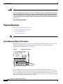
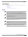
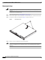
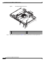
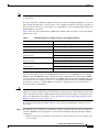
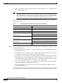
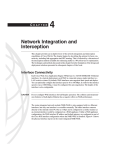
Installing the Cisco WAE Inline Network Adapter
Product Number: WAE-INLN-4CG=
Models: FE-511-K9, WAE-511-K9, WAE-611-K9, WAE-512-K9, WAE-612-K9, WAE-7326-K9, WAE-7341-K9,
WAE-7371-K9, WAE-674-K9
This document describes how to install the Cisco WAE inline network adapter in your edge or core WAE
appliance. These instructions are intended for experienced technicians.
Note
The Cisco WAE inline network adapter is not supported in a Central Manager appliance. (For more
information, see the “Important Operational Notes” section on page 7.)
Contents
This document contains the following sections:
•
Product Overview
•
Safety Guidelines
•
Important Operational Notes
•
Installing Adapters in the FE-511, WAE-511, and WAE-611 Appliances
•
Installing Adapters in the WAE-512 and WAE-612 Appliances
•
Installing Adapters in the WAE-7326 Appliance
•
Installing Adapters in the WAE-7371, WAE-7341, and WAE-674 Appliances
•
Cabling
•
Related Documentation
•
Obtaining Documentation, Obtaining Support, and Security Guidelines
Americas Headquarters:
Cisco Systems, Inc., 170 West Tasman Drive, San Jose, CA 95134-1706 USA
© 2007–2008 Cisco Systems, Inc. All rights reserved.
Product Overview
Warning
IMPORTANT SAFETY INSTRUCTIONS
This warning symbol means danger. You are in a situation that could cause bodily injury. Before you
work on any equipment, be aware of the hazards involved with electrical circuitry and be familiar
with standard practices for preventing accidents. Use the statement number provided at the end of
each warning to locate its translation in the translated safety warnings that accompanied this device.
Statement 1071
SAVE THESE INSTRUCTIONS
Product Overview
This section contains the following topics:
Note
•
Inline Network Adapter Description
•
Ports and LED Indicators
•
Adapter Specifications
The minimum software release required for the inline network adapter is WAAS 4.0.7.
Inline Network Adapter Description
The WAE appliance supports one optional 4-port Ethernet inline network adapter. The inline network
adapter is a full-height, three-quarter-length PCI-X network interface card that contains four
independent Gigabit Ethernet ports. (See Figure 1.)
Inline Network Adapter
159701
Figure 1
The Cisco WAE inline network adapter provides an inline traffic interception capability for your
appliance. When you configure the WAE appliance for inline interception mode, you can set attributes
to control which interfaces are to be used over which VLANs. By default, the adapter operates on all
inline-capable interfaces and VLANs. You can configure the inline redirection feature using the WAAS
4.0.7 CLI or the WAAS 4.0.7 Central Manager GUI.
Installing the Cisco WAE Inline Network Adapter
2
OL-12480-03
Product Overview
The WAAS software defines two new interface types: A group interface that represents an inline pair
grouping and a port interface that represents the individual port. These interfaces are referred to as
inlineGroup and inlinePort.
InlineGroup interfaces are numbered using the format slot/group. The slot number is the slot in which
the adapter is inserted. (In the WAE 500 series and 600 series appliances, you must install the adapter in
slot 1 only.) The group number is either 0 or 1 (each adapter has 2 group pairs). The group number is
displayed on the adapter label.
InlinePort interfaces are numbered slot/group/lan or slot/group/wan. The last attribute is the LAN or
WAN designator.
The inline network adapter also includes an onboard programmable watch dog timer (WDT) controller
that allows you to set the time to wait after a failure event, such as a power outage or a kernel crash,
before the unit begins to operate in mechanical bypass mode. In mechanical bypass mode, traffic is
bridged between the LAN and WAN ports of each group. Mechanical bypass mode prevents the WAE
from becoming a single point of failure and allows traffic to continue to flow between the router and the
client while it passes through an unresponsive WAE without being processed.
For more information about configuring the inline network adapter, see the Cisco Wide Area Application
Services Configuration Guide.
Ports and LED Indicators
Figure 2 shows the inline network adapter port numbers, interface designations, and LEDs.
Figure 2
Inline Network Adapter Port Numbering and LEDs
W1
L1
W0
L0
LINK/ACT
W1
L1
W0
BYPASS
272072
100
1000
L0
W1 Port WAN1; Group 1 WAN interface
L1
Port LAN1; Group 1 LAN interface
W0 Port WAN0; Group 0 WAN interface
L0
Port LAN0: Group 0 LAN interface
The inline network adapter has three LEDs that correspond to each port (the W1 LEDs correspond to
Port W1, and so forth). Table 1 describes the LEDs.
Table 1
Inline Network Adapter LEDs
LEDs
State
Description
Link / Activity
On
The 10/100/1000BASE-T interface is receiving power.
Blinking
The Ethernet link is transmitting data.
On
The speed of the Ethernet connection is 100BASE-TX.
100
Installing the Cisco WAE Inline Network Adapter
OL-12480-03
3
Product Overview
Table 1
Note
Inline Network Adapter LEDs (continued)
LEDs
State
Description
1000
On
The speed of the Ethernet connection is 1000BASE-TX.
Bypass
Both the 100 and
1000 LEDs are on
The corresponding ports are in mechanical bypass mode.
On older inline network adapters, the LEDs are labelled 0, 1, 2, and 3. These correspond to W1, L1, W0,
and L0 respectively.
Adapter Specifications
Table 2 describes the inline network adapter technical and general specifications.
Table 2
Inline Network Adapter Specifications
Specification
Description
Copper Gigabit Ethernet Specifications
IEEE standard
Gigabit Ethernet, 1000BASE-T
Fast Ethernet, 100BASE-T
Ethernet, 10BASE-T
Full duplex and half duplex
Supports both half-duplex and full-duplex operation in all
operating speeds
Autonegotiation
Autonegotiates between full-duplex and half-duplex operations
and between 1000-Mbps, 100-Mbps, and 10-Mbps speeds
Data transfer rate
1000-Mbps, 100-Mbps, and 10-Mbps speeds per port in
half-duplex mode
2000-Mbps, 200-Mbps, and 20-Mbps speeds per port in
full-duplex mode
General Technical Specifications
Interface standard
PCI v2.2 32/64 bit, 33/66 MHz
PCI-X v1.0 32/64 bit, 66/100/133 MHz
Size
6.6 x 4.2 in. (167.64 x 106.68 mm)
PCI connector
Universal 64-bit connector
PCI voltage
+12 V (minimum 11.4 V, maximum 12.6 V)
+3.3 V (minimum 3.0 V, maximum 3.6 V)
Weight
6.18 oz (175 grams)
Operating humidity
0 to 90%, noncondensing
Operating temperature
32 to –122oF (0 to 50oC)
Storage temperature
–4 to –149oF (–20 to –65oC)
Installing the Cisco WAE Inline Network Adapter
4
OL-12480-03
Safety Guidelines
Safety Guidelines
To reduce the risk of bodily injury, electrical shock, fire, and damage to the equipment, observe the
following precautions:
•
Warnings
•
General Precautions
•
Protecting Against Electrostatic Discharge
Warnings
Warning
This equipment must be grounded. Never defeat the ground conductor or operate the equipment in the
absence of a suitably installed ground conductor. Contact the appropriate electrical inspection
authority or an electrician if you are uncertain that suitable grounding is available. Statement 1024
Warning
The safety cover is an integral part of the product. Do not operate the unit without the safety cover
installed. Operating the unit without the cover in place will invalidate the safety approvals and pose
a risk of fire and electrical hazards. Statement 117
Warning
Blank faceplates (filler panels) serve three important functions: they prevent exposure to hazardous
voltages and currents inside the chassis; they contain electromagnetic interference (EMI) that might
disrupt other equipment; and they direct the flow of cooling air through the chassis. Do not operate
the system unless all cards and faceplates are in place. Statement 156
Warning
Only trained and qualified personnel should be allowed to install, replace, or service this equipment.
Statement 1030
Warning
This unit is intended for installation in restricted access areas. A restricted access area can be
accessed only through the use of a special tool, lock and key, or other means of security.
Statement 1017
Installing the Cisco WAE Inline Network Adapter
OL-12480-03
5
Safety Guidelines
General Precautions
Observe the following general precautions for using and working with your system:
•
Observe and follow service markings. Do not service any Cisco product except as explained in your
system documentation. Opening or removing covers that are marked with the triangular symbol with
a lightning bolt may expose you to electrical shock. Components inside these compartments should
be serviced only by an authorized service technician.
•
If any of the following conditions occur, unplug the product from the electrical outlet and replace
the part or contact your authorized service provider:
– The power cable or plug is damaged.
– An object has fallen into the product.
– The product has been exposed to water.
– The product has been dropped or damaged.
– The product does not operate correctly when you follow the operating instructions.
•
Keep your system components away from radiators and heat sources. Also, do not block cooling
vents.
•
Do not spill food or liquids on your system components, and never operate the product in a wet
environment.
•
Do not push any objects into the openings of your system components. Doing so can cause fire or
electric shock by shorting out interior components.
•
Use the product only with other Cisco-approved equipment.
•
Allow the product to cool before removing covers or touching internal components.
•
Use the correct external power source. Operate the product only from the type of power source
indicated on the electrical ratings label. If you are not sure of the type of power source required,
consult your service representative or local power company.
•
Use only approved power cables. If you have not been provided with a power cable for your
Content Engine or for any AC-powered option intended for your system, purchase a power cable that
is approved for use in your country. The power cable must be rated for the product and for the
voltage and current marked on the product’s electrical ratings label. The voltage and current rating
of the cable should be greater than the ratings marked on the product.
•
To help prevent electric shock, plug the system components and peripheral power cables into
properly grounded electrical outlets. These cables are equipped with three-prong plugs to help
ensure proper grounding. Do not use adapter plugs or remove the grounding prong from a cable.
•
Do not use appliance or voltage converters or kits sold for appliances with your product.
•
To help protect your system components from sudden, transient increases and decreases in electrical
power, use a surge suppressor or line conditioner.
•
Position cables and power cords carefully; route cables and the power cord and plug so that they
cannot be stepped on or tripped over. Be sure that nothing rests on your system components’ cables
or power cord.
•
Do not modify power cables or plugs. Consult a licensed electrician or your power company for site
modifications. Always follow your local or national wiring rules.
Installing the Cisco WAE Inline Network Adapter
6
OL-12480-03
Important Operational Notes
Protecting Against Electrostatic Discharge
Static electricity can harm delicate components inside your system. To prevent static damage, discharge
static electricity from your body before you touch any of your system’s electronic components. You can
do so by touching an unpainted metal surface on the chassis.
You can also take the following steps to prevent damage from electrostatic discharge (ESD):
•
Limit your movement. Movement can cause static electricity to build up around you.
•
When transporting a sensitive component, first place it in an antistatic container or packaging.
•
Just before unwrapping the antistatic packaging, be sure to discharge static electricity from your
body by touching it to an unpainted metal part of the system unit for at least 2 seconds.
•
Remove the adapter from its packaging and install it directly into your system unit without setting
it down. If it is necessary to set the adapter down, place it in its static-protective package. Do not
place the adapter on your system unit cover or on a metal table.
•
Handle all sensitive components in a static-safe area. If possible, use antistatic floor pads and
workbench pads.
•
Handle the adapter carefully, holding it by its edges or its frame.
•
Do not touch solder joints, pins, or exposed printed circuitry.
•
Do not leave the adapter where others can handle and possibly damage the adapter.
•
Take additional care when handling adapters during cold weather because heating reduces indoor
humidity and increases static electricity.
Important Operational Notes
If you intend to reconfigure an edge or core WAE with a Cisco WAE inline network adapter installed in
it as a Central Manager device, first remove the inline network adapter. The inline network adapter is not
supported in a Central Manager appliance.
Installing Adapters in the FE-511, WAE-511, and WAE-611
Appliances
This section describes how to install the inline network adapter in the FE-511, WAE-511, and the
WAE-611 appliances. This section includes the following procedures:
•
Removing the Cover
•
Installing an Inline Network Adapter
•
Completing the Installation
Installing the Cisco WAE Inline Network Adapter
OL-12480-03
7
Installing Adapters in the FE-511, WAE-511, and WAE-611 Appliances
Removing the Cover
Warning
Before working on a system that has an on/off switch, turn OFF the power and unplug the power cord.
Statement 1
To remove the cover, follow these steps:
Step 1
Review the information in the “Safety Guidelines” section on page 5.
Step 2
Power down the appliance and all attached devices. Disconnect the power cord and all external cables.
Step 3
Loosen the two captive screws (labeled 1 in Figure 3) on the rear of the cover.
Figure 3
Removing the Cover
115802
1
Step 4
Caution
Slide the cover back, and then lift it up and off the appliance.
For proper cooling and airflow, replace the cover before turning on the appliance. Operating the
appliance for extended periods (over 30 minutes) with the cover removed might damage appliance
components.
Installing the Cisco WAE Inline Network Adapter
8
OL-12480-03
Installing Adapters in the FE-511, WAE-511, and WAE-611 Appliances
Installing an Inline Network Adapter
Before you install an adapter, review the following information:
•
The adapter slots are on the riser card assembly. You must first remove the riser card assembly to
access the adapter slots. (See Figure 4.)
•
The appliance has two Peripheral Component Interconnect-Extended (PCI-X) adapter slots:
– PCI-X slot 1 is for one full-height three-quarter-length adapter.
– PCI-X slot 2 is for one low-profile half-length adapter; however, it is not used in this appliance.
•
Caution
Note
You must install the inline network adapter in PCI-X slot 1. (This slot is labeled “PCI 1” on the back
of the appliance.)
When you handle static-sensitive adapters and appliances, take precautions to avoid damage from static
electricity. For details on handling these devices, see the “Protecting Against Electrostatic Discharge”
section on page 7.
The illustrations in this document might differ slightly from your hardware.
To install an inline network adapter, follow these steps:
Step 1
Review the safety information in the “Safety Guidelines” section on page 5.
Step 2
Power down the appliance and peripheral devices.
Step 3
Disconnect the power cord and then all external cables from the appliance.
Step 4
Remove the appliance cover.
Note
Step 5
You may find it easier to route the cables before you install the adapter.
Loosen the captive screw (labeled 3 in Figure 4) located on the rear of the appliance adjacent to PCI-X
slot 1 and remove the expansion slot cover.
Note
You must install PCI expansion slot covers on all vacant slots so that you can maintain the
electronic emissions characteristics of the appliance and ensure proper cooling of internal
components.
Installing the Cisco WAE Inline Network Adapter
OL-12480-03
9
Installing Adapters in the FE-511, WAE-511, and WAE-611 Appliances
Removing the Expansion Slot Cover
124478
Figure 4
1
2
4
3
Step 6
1
Expansion slot cover (slot 2)
2
Expansion slot cover (slot 1)
3
Captive screw
4
Riser card assembly
Remove the riser card (labeled 1 in Figure 5) from the system board to access the expansion slot.
Installing the Cisco WAE Inline Network Adapter
10
OL-12480-03
Installing Adapters in the FE-511, WAE-511, and WAE-611 Appliances
Figure 5
Installing an Adapter in the Riser Card Assembly
1
2
3
4
124479
5
6
1
Riser card
2
PCI-X slot 2 connector
3
PCI-X slot 1 connector
4
Adapter support bracket
5
Adapter
6
PCI-X riser card connector
Step 7
Touch the static-protective package that contains the adapter to any unpainted metal surface on the
appliance, and then remove the adapter from the static-protective package. Avoid touching the
components and gold-plated edge connectors on the adapter.
Step 8
Place the adapter, component-side up, on a flat, static-protective surface and set any jumpers or switches
as described by the adapter manufacturer, if necessary.
Caution
When you install an adapter in the appliance, be sure that it is completely and correctly seated in the PCI
expansion slot before you power up the appliance. Incomplete insertion might cause damage to the
system board or the adapter.
Step 9
To install the adapter, carefully grasp the adapter by its top edge or upper corners, align it with the PCI-X
slot 1 connector (labeled 3 in Figure 5), and then press the adapter firmly into the expansion slot.
Installing the Cisco WAE Inline Network Adapter
OL-12480-03
11
Installing Adapters in the FE-511, WAE-511, and WAE-611 Appliances
Step 10
Reinstall the riser card. Make sure that the riser card is fully seated in the riser card connector (labeled
6 in Figure 5) on the system board.
Step 11
Tighten the captive screw for expansion slot 1.
Step 12
Connect the required cables to the adapter.
Completing the Installation
To complete your installation, reinstall the cover and reconnect all cables that you disconnected earlier.
Caution
To maintain proper cooling and airflow, install the cover before turning on the appliance. Operating the
appliance for extended periods (over 30 minutes) with the cover removed might damage internal
components.
To install the cover, follow these steps:
Step 1
Caution
Install the cover by placing it into position and sliding it forward, and then tighten the captive screws
(labeled 1 in Figure 6).
Before sliding the cover forward, make sure that the cover will properly engage the ledge at the front of
the appliance.
Figure 6
Installing the Cover
115802
1
Step 2
Install the appliance in the rack.
Installing the Cisco WAE Inline Network Adapter
12
OL-12480-03
Installing Adapters in the WAE-512 and WAE-612 Appliances
Step 3
Connect all external cables and the power cord to the appliance, and then plug the power cord into a
properly grounded electrical outlet.
Installing Adapters in the WAE-512 and WAE-612 Appliances
This section describes how to install the inline network adapter in the WAE-512 and the WAE-612
appliances. This section includes the following procedures:
•
Removing the Cover
•
Installing an Inline Network Adapter
•
Completing the Installation
Removing the Cover
Warning
Before working on a chassis or working near power supplies, unplug the power cord on AC units.
Statement 246
To remove the cover, follow these steps:
Step 1
Review the information in the “Safety Guidelines” section on page 5.
Step 2
Power down the device and all attached devices. Disconnect the power cord and all external cables.
Step 3
Press the cover release button (labeled 1 in Figure 7).
Figure 7
Removing the Cover
151926
1
Cisc
o WA
E 50
0 Se
ries
Step 4
While holding the cover release button down with your thumb, lift the opposite front corner of chassis
slightly with your other hand, and using your free thumb, slide the cover back approximately 0.5 inches
(1.27 cm); then lift it up and off the device.
Installing the Cisco WAE Inline Network Adapter
OL-12480-03
13
Installing Adapters in the WAE-512 and WAE-612 Appliances
Caution
For proper cooling and airflow, replace the cover before turning on the device. Operating the device for
extended periods (over 30 minutes) with the cover removed might damage device components.
Installing an Inline Network Adapter
Before you install adapters, review the following information:
•
The adapter slots are on the riser card assembly. You must first remove the riser card assembly to
access the adapter slots. (See Figure 8.)
•
The device has two Peripheral Component Interconnect-Extended (PCI-X) adapter slots:
– PCI-X slot 1 is for one full-height three-quarter-length adapter.
– PCI-X slot 2 is for one low-profile half-length adapter; however, it is not used in this device.
•
Caution
Note
You must install supported adapters in PCI-X slot 1. (This slot is labeled “Slot 1” on the back of the
device.)
When you handle static-sensitive devices, take precautions to avoid damage from static electricity. For
details on handling these devices, see the “Protecting Against Electrostatic Discharge” section on
page 7.
The illustrations in this document might differ slightly from your hardware.
To install an adapter, follow these steps:
Step 1
Review the safety information in the “Safety Guidelines” section on page 5.
Step 2
Power down the device and peripheral devices.
Step 3
Disconnect the power cord and then all external cables from the device.
Step 4
Remove the device cover.
Step 5
Grasp the riser card at the rear edge and lift to remove the riser card assembly. (See Figure 8.)
Installing the Cisco WAE Inline Network Adapter
14
OL-12480-03
Installing Adapters in the WAE-512 and WAE-612 Appliances
Figure 8
Removing the Riser Card Assembly
1
Front
151927
2
Rear
1
Riser card assembly
2
Rear edge of riser card
Step 6
Place the riser card assembly on a flat, static-protective surface.
Step 7
Remove the expansion slot cover for Slot 1. (See Figure 9.)
Note
You must install PCI expansion slot covers on all vacant slots so that you can maintain the
electronic emissions characteristics of the appliance and ensure proper cooling of internal
components.
Installing the Cisco WAE Inline Network Adapter
OL-12480-03
15
Installing Adapters in the WAE-512 and WAE-612 Appliances
Figure 9
Installing the Adapter in the Riser Card Assembly
2
3
1
4
5
151928
6
7
1
Expansion slot bracket
2
Adapter
3
Adapter support bracket
4
PCI-X expansion slot 1
5
Riser card assembly
6
PCI-X expansion slot 2 (not supported)
7
Riser card connectors
Step 8
Touch the static-protective package that contains the adapter to any unpainted metal surface on the
device, and then remove the adapter from the static-protective package. Avoid touching the components
and gold-plated edge connectors on the adapter.
Step 9
Place the adapter, component-side up, on a flat, static-protective surface.
Caution
When you install an adapter in the device, be sure that it is completely and correctly seated in the PCI
expansion slot before you power up the device. Incomplete insertion might cause damage to the system
board or the adapter.
Step 10
To install the adapter, carefully grasp the adapter by its top edge or upper corners, align it with the
expansion slot in the riser card assembly, and then press the adapter firmly into the expansion slot.
Step 11
Reinstall the riser card. Make sure that the riser card is fully seated in the riser card connectors on the
system board.
Installing the Cisco WAE Inline Network Adapter
16
OL-12480-03
Installing Adapters in the WAE-7326 Appliance
Completing the Installation
To complete your installation, reinstall the cover and reconnect all cables that you disconnected earlier.
Caution
To maintain proper cooling and airflow, install the cover before turning on the appliance. Operating the
appliance for extended periods (over 30 minutes) with the cover removed might damage internal
components.
To install the cover, follow these steps:
Step 1
Install the cover by placing it into position and sliding it forward. (See Figure 10.)
Installing the Cover
151932
Figure 10
Cisc
o WA
E 50
0 Se
ries
Caution
Before sliding the cover forward, make sure that the cover will properly engage the ledge at the front of
the device.
Step 2
Install the device in the rack.
Step 3
Connect all external cables and the power cord to the device, and then plug the power cord into a properly
grounded electrical outlet.
Installing Adapters in the WAE-7326 Appliance
This section describes how to install the inline network adapter in the WAE-7326 appliance. This section
includes the following procedures:
•
Removing the Cover
•
Installing an Inline Network Adapter
•
Completing the Installation
Installing the Cisco WAE Inline Network Adapter
OL-12480-03
17
Installing Adapters in the WAE-7326 Appliance
Removing the Cover
Warning
Before working on a system that has an on/off switch, turn OFF the power and unplug the power cord.
Statement 1
To remove the device top cover, follow these steps:
Step 1
Review the information in the “Safety Guidelines” section on page 5.
Step 2
Power off the device and all attached devices and disconnect all external cables and power cords.
Step 3
Press down on the left and right side latches and pull the device out of the rack enclosure until both slide
rails lock.
Note
Step 4
You can reach the cables on the back of the device when the device is in the locked position.
Lift the cover-release latch (labeled 1 in Figure 11). Lift the cover off the device and set the cover aside.
Removing the Cover
159947
Figure 11
1
Caution
For proper cooling and airflow, replace the cover before turning on the device. Operating the device for
extended periods (over 30 minutes) with the cover removed might damage device components.
Installing the Cisco WAE Inline Network Adapter
18
OL-12480-03
Installing Adapters in the WAE-7326 Appliance
Installing an Inline Network Adapter
The WAE-7326 has connectors for up to four PCI adapters on the system board and PCI riser card. You
can install the inline network adapter in slot 3 (labeled 1 in Figure 12) or in slot 4 (labeled 2 Figure 12)
in on the PCI riser card.
Note
The PCI riser card is located at J73 on the system board.
Figure 12
PCI-X Riser Card
137707
1
2
1
PCI-X slot 3, 64 bit 3.3 V 133 MHz (PCI 3)
2
PCI-X slot 4, 64 bit 3.3 V 133 MHz (PCI 4)
To install an inline network adapter, follow these steps:
Step 1
Review the information in the “Safety Guidelines” section on page 5.
Step 2
Power down the device and peripheral devices and disconnect all power cords and external cables.
Step 3
Remove the cover. (See the “Removing the Cover” section on page 18.)
Step 4
Remove the PCI riser card assembly.
Step 5
Slide the expansion-slot cover out of the PCI riser card cage.
Step 6
Touch the static-protective package that contains the adapter to any unpainted metal surface on the
device, and then remove the adapter from the static-protective package. Avoid touching the components
and gold-plated edge connectors on the adapter.
Step 7
Place the adapter, component-side up, on a flat, static-protective surface.
Caution
When you install an adapter in the device, be sure that it is completely and correctly seated in the PCI
expansion slot before you power up the device. Incomplete insertion might cause damage to the system
board or the adapter.
Step 8
To install the adapter, carefully grasp the adapter by its top edge or upper corners, align it with the
expansion slot in the riser card assembly, and then press the adapter firmly into the expansion slot.
Step 9
Reinstall the riser card. Make sure that the riser card is fully seated in the riser card connectors on the
system board.
Step 10
Connect any needed cables to the adapter.
Installing the Cisco WAE Inline Network Adapter
OL-12480-03
19
Installing Adapters in the WAE-7326 Appliance
Figure 13 shows the cable routing for an adapter installed in the PCI riser card cage.
Figure 13
Cable Routing for the PCI Riser Card Cage
137691
1
2
1
Caution
Note
Riser card cage
2
SCSI cable
When you route cables, do not block any connectors or the ventilated space around any of the fans.
Make sure that cables are not routed on top of components under the PCI riser card assembly.
Make sure that cables are not pinched by the server components.
Remove the fan guide before you route the cables. Reinstall the fan guide when you complete the cable
routing.
Installing the Cisco WAE Inline Network Adapter
20
OL-12480-03
Installing Adapters in the WAE-7326 Appliance
Completing the Installation
To complete your installation, reinstall the cover, and reconnect all cables that you disconnected earlier.
Caution
To maintain proper cooling and airflow, install the cover before turning on the appliance. Operating the
appliance for extended periods (over 30 minutes) with the cover removed might damage internal
components.
To install the cover, follow these steps:
Step 1
Place the cover release latch (labeled 1 in Figure 14) in the open (up) position.
Step 2
Insert the bottom tabs of the top cover into the matching slots in the device chassis.
Step 3
Press down on the cover release latch to lock the cover in place.
Installing the Cover
159947
Figure 14
1
Step 4
Install the appliance in the rack.
Step 5
Connect all external cables and the power cord to the appliance, and then plug the power cord into a
properly grounded electrical outlet.
Installing the Cisco WAE Inline Network Adapter
OL-12480-03
21
Installing Adapters in the WAE-7371, WAE-7341, and WAE-674 Appliances
Installing Adapters in the WAE-7371, WAE-7341, and WAE-674
Appliances
This section describes how to install the inline network adapter in the WAE-7371, 7341, and 674
appliances. This section includes the following procedures:
•
Removing the Cover
•
Installing an Inline Network Adapter
•
Completing the Installation
Removing the Cover
Warning
Before working on a system that has an on/off switch, turn OFF the power and unplug the power cord.
Statement 1
To remove the device top cover, follow these steps:
Step 1
Review the information in the “Safety Guidelines” section on page 5.
Step 2
Power off the device and all attached devices and disconnect all external cables and power cords.
Step 3
Press down on both side latches and pull the device out of the rack enclosure until both slide rails lock.
Note
Step 4
You can reach the cables on the back of the device when the device is in the locked position.
Lift the cover-release latch (see Figure 15). Lift the cover off the device and set the cover aside.
Figure 15
Removing the Cover
185089
Cover-release latch
Installing the Cisco WAE Inline Network Adapter
22
OL-12480-03
Installing Adapters in the WAE-7371, WAE-7341, and WAE-674 Appliances
Caution
For proper cooling and airflow, replace the cover before turning on the device. Operating the device for
extended periods (over 30 minutes) with the cover removed might damage device components.
Installing an Inline Network Adapter
The WAE-7371, WAE-7341, and WAE-674 have connectors for up to four PCI adapters on the system
board and PCI riser card. You can install the inline network adapter in slot 1 or in slot 2 on the PCI riser
card.
To install an inline network adapter in the riser-card assembly, follow these steps:
Step 1
Review the information in the “Safety Guidelines” section on page 5.
Step 2
Power down the device and peripheral devices and disconnect all power cords and external cables.
Step 3
Remove the cover. (See the “Removing the Cover” section on page 22.)
Step 4
Remove the PCI-X riser-card assembly. (See Figure 16.) Push the two riser-card assembly release tabs
toward the PCI-X slots. Grasp the assembly at the rear and side edges and lift it to remove it from the
WAE. Place the riser-card assembly on a flat, static-protective surface.
Figure 16
Removing the PCI-X Riser-Card Assembly
Access holes
185090
Release tabs
Step 5
Determine which expansion slot that you will use for the adapter. You can install the Cisco WAE Inline
Network Adapter card in slot 1 or slot 2 on the riser-card.
Step 6
Slide the expansion-slot cover out of the PCI-X riser-card assembly expansion slot.
Installing the Cisco WAE Inline Network Adapter
OL-12480-03
23
Installing Adapters in the WAE-7371, WAE-7341, and WAE-674 Appliances
Install the adapter, as shown in Figure 17. The riser-card assembly is shown inverted in Figure 17.
Figure 17
Installing the Adapter in the Riser-Card Assembly
Inverted riser assembly
Step 8
Caution
185091
Step 7
Connect any needed cables to the adapter.
When you route cables, do not block any connectors or the ventilated space around any of the fans.
Make sure that cables are not routed on top of components under the PCI-X riser-card assembly.
Make sure that cables are not pinched by the device components.
Step 9
Carefully align the riser-card assembly with the release tab posts, the guides on the rear of the WAE, and
the riser-card connector on the system board. Press down on the assembly. (See Figure 18.) Make sure
that the riser-card assembly is fully seated in the riser-card connector on the system board.
Installing the Cisco WAE Inline Network Adapter
24
OL-12480-03
Installing Adapters in the WAE-7371, WAE-7341, and WAE-674 Appliances
Figure 18
Installing the PCI-X Riser-Card Assembly
Access holes
Guide
Release tabs
185092
Guide
Step 10
Perform any configuration tasks required for the adapter.
Step 11
Reinstall the cover.
For instructions on completing the installation, see the “Completing the Installation” section on page 26.
Installing the Cisco WAE Inline Network Adapter
OL-12480-03
25
Cabling
Completing the Installation
To complete your installation, follow these steps:
Step 1
Install the top cover by placing the cover-release latch in the open (up) position. Insert the bottom tabs
of the top cover into the matching slots in the WAE chassis. Press down on the cover-release latch to lock
the cover in place, as shown in Figure 19.
Figure 19
Installing the Cover
185093
Cover-release latch
Step 2
Install the device in a rack.
Step 3
Connect all external cables and power cords to the appliance, and then plug the power cords into a
properly grounded electrical outlet.
Cabling
The inline network adapter ships with two types of cables: crossover and straight-through. When you
connect the WAE inline network adapter, the cable that you use depends on the link speed (Gigabit
Ethernet or Fast Ethernet) and the types of devices (DCE or DTE) being connected.
Note
You must retain the same link speed from one end of the connection to the other end. Inline adapter
interfaces are able to autonegotiate link speeds. If you configure any of your connecting interfaces for
Fast Ethernet (whether on a switch or a router), your WAE inline adapter uses Fast Ethernet. If you
configure any of your connecting interfaces for Gigabit Ethernet, your WAE inline adapter uses Gigabit
Ethernet. Speed and duplex settings are port specific so that two inline ports can negotiate different
speeds independently.
Installing the Cisco WAE Inline Network Adapter
26
OL-12480-03
Cabling
Note
We strongly recommend that you do not use half-duplex connections on the WAE or on routers, switches,
or other devices.
If you are connecting a WAE inline appliance between two devices using Gigabit Ethernet, you can use
either straight-through cables, crossover cables, or any combination of the two cable types, regardless of
the type of device. However, for consistency, we recommend that you use straight-through cables for all
Gigabit Ethernet connections.
Table 3 shows the cable requirements for WAE and non-WAE connections when you are using Gigabit
Ethernet end to end.
Table 3
Cable Requirements for WAE Connections Using Gigabit Ethernet
Connection
Required Cable
Switch to switch (no WAE)
Crossover or straight-through
Switch to router (no WAE)
Crossover or straight-through
Router to router (no WAE)
Crossover or straight-through
Switch to WAE and
Crossover or straight-through
WAE to Router
Crossover or straight-through
Switch to WAE and
Crossover or straight-through
WAE to Switch
Crossover or straight-through
Router to WAE and
Crossover or straight-through
WAE to Router
Crossover or straight-through
WAE to WAE
Crossover or straight-through
Some switches support automatic medium-dependent interface crossover (MDIX). You can configure
MDIX by using the mdix auto global configuration switch command. If your switch supports MDIX,
you do not need to follow these cabling rules because MDIX automatically adjusts transmit and receive
pairs when an incorrect cable type (crossover or straight-through) is installed on a 10/100 Fast Ethernet
port. However, when you configure MDIX, you must also configure the port to use autosense (not
manual selection of speed/duplex).
Caution
If you are connecting to Fast Ethernet ports on both the LAN and the WAN sides of the WAE inline
appliance, you must consider the types of devices that are being connected, and you must use the correct
cables. You must follow these cabling instructions for the inline network adapter to work properly. (See
Table 4. For illustrations and examples, see the “Installation Scenarios and Cabling Examples for Fast
Ethernet Connections” section on page 29.)
To connect the inline network adapter using the correct cables for Fast Ethernet connections, follow
these steps:
Step 1
Determine the type of cable that you would use for a direct connection between your two end devices
(without a WAE inline network appliance connected between them) by using the following standard
cabling rules:
•
When you are directly connecting two network devices that are similar, such as two switches, use a
crossover cable.
Installing the Cisco WAE Inline Network Adapter
OL-12480-03
27
Cabling
•
When you are directly connecting two network devices that are different, such as a switch and router,
use a straight-through cable.
Because the inline network adapter has an internal crossover connection that becomes active
when the InlineGroup interface is placed in mechanical bypass mode, you must decide which
cable you would use to connect the two network devices directly, and then you must install the
other cable type (on one side, usually the WAN side of the inline appliance) instead.
Note
Table 4 shows the cable requirements for WAE and non-WAE connections when you are using Fast
Ethernet end to end.
Table 4
Step 2
Cable Requirements for WAE Connections Using Fast Ethernet
Connection
Required Cable
Switch to switch (no WAE)
Crossover
Switch to router (no WAE)
Straight-through
Router to router (no WAE)
Crossover
Switch to WAE and
Straight-through
WAE to Router
Crossover
Switch to WAE and
Straight-through
WAE to Switch
Straight-through
Router to WAE and
Straight-through
WAE to Router
Straight-through
WAE to WAE
Crossover
Connect Fast Ethernet ports on both the LAN and the WAN sides of the WAE inline appliance by using
the following cable types:
•
On the LAN side of the connection, use a straight-through cable between the WAE inline appliance
and the network device.
•
On the WAN side of the connection, use the cable that is different from the cable that you would use
to connect the two network devices directly (as determined in Step 1).
For example, if you are connecting a router and a switch (two different devices) through the WAE
inline appliance, use a straight-through cable on the LAN side of the connection and use a crossover
cable on the WAN side of the connection. (If you were connecting the two different devices directly,
you would use a straight-through cable, so use the crossover cable instead.)
If you are connecting two switches (or two similar devices), use straight-through cables on both the
LAN and the WAN sides of the WAE inline appliance.
Figure 20 through Figure 22 show which cables to use for the WAE LAN and WAN connections
between Fast Ethernet ports.
Installing the Cisco WAE Inline Network Adapter
28
OL-12480-03
Cabling
Installation Scenarios and Cabling Examples for Fast Ethernet Connections
WAE appliances can be installed physically between two network devices (such as the branch office
router and branch office LAN switch) by connecting the WAE inline network adapter ports to the
network devices using the proper cables.
If you are connecting a WAE inline appliance between two devices using Gigabit Ethernet, you can use
either straight-through cables, crossover cables, or any combination of the two cable types, regardless of
the type of device. This section shows cabling examples for Fast Ethernet connections only, because Fast
Ethernet has specific cabling requirements.
The inline network adapter has four ports that are divided into two inline groups (see the “Ports and LED
Indicators” section on page 3). The WAE can be physically placed inline between two distinct network
paths, creating redundant WAN links. (See Figure 20.)
Two WAEs with inline network adapters can also be installed back-to-back in a serial fashion between
two network devices for failover purposes. In this serial cluster configuration, if one WAE fails or
becomes overloaded, the other WAE can provide optimization. (See Figure 21.)
Note
When you connect two WAE inline appliances to each other serially, always use a crossover cable
between the two WAEs. (See Figure 22.)
Figure 20
Cabling for a Single Inline WAE with Redundant WAN Connections
1
MGMT
WAN
4
2
3
WAE
5
WAN
Router B
1
Connection: Management
2
Gigabit Ethernet: 1/0
240087
LAN switch
Router A
Connection: WAE to LAN switch
(using InlineGroup 1/0)
Fast Ethernet: LAN0 (InlinePort 1/0/lan)
Cable type: Straight-through (recommended)
Cable type: Straight-through
3
5
Connection: WAE to LAN switch
(using InlineGroup 1/1)
4
Connection: WAE to WAN router A
(using InlineGroup 1/0)
Fast Ethernet: LAN1 (InlinePort 1/1/lan)
Fast Ethernet: WAN0 (InlinePort 1/0/wan)
Cable type: Straight-through
Cable type: Crossover
Connection: WAE to WAN router B
(using InlineGroup 1/1)
Fast Ethernet: WAN1 (InlinePort 1/1/wan)
Cable type: Crossover
Installing the Cisco WAE Inline Network Adapter
OL-12480-03
29
Cabling
Figure 21
Cabling for Serial Cluster Inline WAEs with a Single WAN Connection
WAN
1
LAN switch
1
2
3
WAE1
WAE2
2
Connection: WAE 1 to LAN switch
Router B
Connection: WAE 1 to WAE 2
Fast Ethernet: WAE1 WAN0
(InlinePort 1/0/wan) to WAE 2 LAN0
(InlinePort 1/0/lan)
Fast Ethernet: LAN0 (InlinePort 1/0/lan)
Cable type: Straight-through
Cable type: Crossover
3
Connection: WAE 2 to WAN router
Fast Ethernet: WAE 2 WAN0
(InlinePort 1/0/wan)
Cable type: Crossover
Figure 22
Cabling Between Two Inline WAEs
WAN
3
WAE2
inline adapter
Router
0
1
2
3
BYPASS
LINK/ACT
100
1000
2
WAE1
inline adapter
1
0
1
LAN switch
3
BYPASS
Fast Ethernet: WAE 1 LAN0
(InlinePort 1/0/lan)
Cable type: Straight-through
2
LINK/ACT
100
1000
Connection: WAE 1 to LAN switch
240089
2
1
Connection: WAE 1 to WAE 2
Fast Ethernet: WAE 1 WAN0
(InlinePort 1/0/wan) to WAE 2 LAN0
(InlinePort 1/0/lan)
Cable type: Crossover
3
Connection: WAE 2 to WAN router
Fast Ethernet: WAE 2 WAN0
(InlinePort 1/0/wan)
Cable type: Crossover
Installing the Cisco WAE Inline Network Adapter
30
OL-12480-03
240088
MGMT
Related Documentation
Related Documentation
For additional information about the Cisco Wide Area Application Engine hardware and the Cisco Wide
Area Application Services (WAAS) software, see the following documentation:
•
Cisco Wide Area Application Engine 7341, 7371, and 674 Hardware Installation Guide
•
Cisco Wide Area Application Engine 7326 Hardware Installation Guide
•
Cisco Wide Area Application Engine 512 and 612 Hardware Installation Guide
•
Cisco Wide Area Application Engine 511 and 611 Hardware Installation Guide
•
Cisco File Engine 511 Hardware Installation Guide
•
Regulatory Compliance and Safety Information for the Cisco Content Networking Product Series
•
Release Note for Cisco Wide Area Application Services
•
Cisco Wide Area Application Services Command Reference
•
Cisco Wide Area Application Services Quick Configuration Guide
•
Cisco Wide Area Application Services Configuration Guide
Obtaining Documentation, Obtaining Support, and Security
Guidelines
For information on obtaining documentation, obtaining support, providing documentation feedback,
security guidelines, and also recommended aliases and general Cisco documents, see the monthly
What’s New in Cisco Product Documentation, which also lists all new and revised Cisco technical
documentation, at:
http://www.cisco.com/en/US/docs/general/whatsnew/whatsnew.html
This document is to be used in conjunction with the documents listed in the “Related Documentation” section.
CCDE, CCENT, Cisco Eos, Cisco Lumin, Cisco Nexus, Cisco StadiumVision, Cisco TelePresence, the Cisco logo, DCE, and Welcome to the Human
Network are trademarks; Changing the Way We Work, Live, Play, and Learn and Cisco Store are service marks; and Access Registrar, Aironet,
AsyncOS, Bringing the Meeting To You, Catalyst, CCDA, CCDP, CCIE, CCIP, CCNA, CCNP, CCSP, CCVP, Cisco, the Cisco Certified Internetwork
Expert logo, Cisco IOS, Cisco Press, Cisco Systems, Cisco Systems Capital, the Cisco Systems logo, Cisco Unity, Collaboration Without Limitation,
EtherFast, EtherSwitch, Event Center, Fast Step, Follow Me Browsing, FormShare, GigaDrive, HomeLink, Internet Quotient, IOS, iPhone, iQ
Expertise, the iQ logo, iQ Net Readiness Scorecard, iQuick Study, IronPort, the IronPort logo, LightStream, Linksys, MediaTone, MeetingPlace,
MeetingPlace Chime Sound, MGX, Networkers, Networking Academy, Network Registrar, PCNow, PIX, PowerPanels, ProConnect, ScriptShare,
SenderBase, SMARTnet, Spectrum Expert, StackWise, The Fastest Way to Increase Your Internet Quotient, TransPath, WebEx, and the WebEx logo
are registered trademarks of Cisco Systems, Inc. and/or its affiliates in the United States and certain other countries.
All other trademarks mentioned in this document or Website are the property of their respective owners. The use of the word partner does not imply
a partnership relationship between Cisco and any other company. (0807R)
Any Internet Protocol (IP) addresses used in this document are not intended to be actual addresses. Any examples, command display output, and
figures included in the document are shown for illustrative purposes only. Any use of actual IP addresses in illustrative content is unintentional and
coincidental.
© 2007–2008 Cisco Systems, Inc. All rights reserved.
Installing the Cisco WAE Inline Network Adapter
OL-12480-03
31
Obtaining Documentation, Obtaining Support, and Security Guidelines
Installing the Cisco WAE Inline Network Adapter
32
OL-12480-03