1
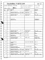
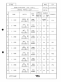
DATE
REV NO
2004
07.05
APPD
DESCRIPTION
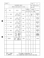
SUBMITTED TO OWNER FOR APPROVAL.
ISSUED FOR WORKING.
*APPgov/frp BV
x K$U£D
g
STAMP AREA
HAERSK WILLOW
.4.8 7
pi);
"jum
'/-vV>
IMO 9303546
DAE 4437
FOR CONST.
G FOR REVISION
PROJ. NO.
PROJECT .
4437/38/41
.
.'
:
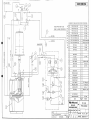
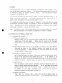
A.P MOLLER 45,000 M2 PURE CAR/TRUCK CARRIER
APPD BY
TITLE
CHKD BY
T
. S. BAEK)
(TEL: 4264)
OWN BY
V/D OF
SIDE THRUSTER
KTE 81 HYUNDAI
DEPT.
DSMG
E-1012
SCALE
HULL OUTFITTING DATE
2004.07.05 AS SHOWN
DESIGN TEAM
DWG
REV NO.
DV4040001
DSME\
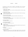
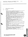
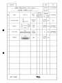
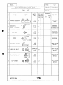
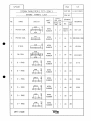
CONTENTS
1. INSTRUCTION MANUAL
FOR BOW & STERN THRUSTER
BOW & STERN
2. STRUCTURE OF BOW THRUSTER
THRUSTER
3. STRUCTURE OF STERN THRUSTER
TCT-220 / 200
4. HYD. PUMP UNIT & HEADER TANK
5. SPARE PARTS & TOOLS LIST
5-1. BOW THRUSTER UNIT
5-2. STERN THRUSTER UNIT
5-3. HYDRAULIC PART
6. NOTE
KTE
NAKASHIMA
KTE CO..LTD.
MECHATRONICS DIVISION
www.kte.co.kr
•
I
I
•
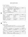
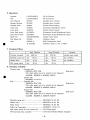
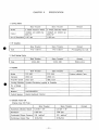
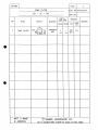
MAIN PARTICULARS
1. Principal Particulars
1.1 Hull
: 45,000m2 PCTC
1.2 Driving Motor (for Side Thrust Unit, Shipyard supply)
Stern Thruster
Bow Thruster
Model
3 Phase Induction Motor
3 Phase Induction Motor
Output
1400kW, AC 6,600V 30
60Hz 6P
1050kW, AC 440V 30
60Hz 6P
No of Revolution
1187 rpm
1185 rpm
Rating
100% SOminute
100% 30minute
Starting Method
Auto-transformer 65% tap
Remark
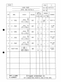
1.3 Thruster
Stern Thruster
Bow Thruster
Model
TCT-220
TCT-200
Propeller Diameter 2200 mm
2000 mm
Propeller Speed
275.6 rpm
303.3 rpm
No. of Blade
4
4
Material
CAC703(A1BC3)
CAC703(A1BC3)
Nominal Thrust
abt. 21.4ton
abt. 16.4ton
Remark
Forward skewed Type
Blade and Hub
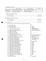
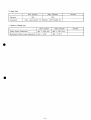
2. Regulation
Rule : DNV
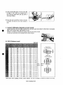
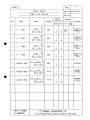
3. Scope of Supply
3.1 Thruster Main Unit (Bow thruster, Stem Thruster)
1 set/vessel
Gear Housing, Propeller Blades, Hub Body, Cross head, Crank Ring, Propeller Shaft, Bearing
Housing, Pinion/Drive Shaft, Crown Wheel, OD box, OT tube, Bearing, Oil Seal, Duct etc.
i seiyvessei
3.6 Dnaii coupling Stern Thruster
Bow Thruster
Type
PTC-1130-H
Remark
PTC-1120-H
Stern Thruster
Bow Thruster
Capacity
85L
85L
Accessory
Filter, Level Switch, Air Breather, Level Gauge etc.
- 1-
Remark
3.4 Hydraulic Pump Unit
Remark
Stern Thruster
Bow Thruster
Electric Motor
5.5kW AC440V, 30, 4P, 60Hz
5.5kW AC440V, 30, 4P, 60Hz
Oil Pump
22.9L/minxlOOkgf/cnf
22.9L/minxlOOkgf/cirf
3.5 Spare Parts (KTE standard)
ror r>c)w inrusier
For St ern Thruster
~
"~
_
~
~
i seu/ vessel
J
1
J
[ set/vessel
3.6 Special Tools (KTE standard)
For Be)W Thruster
1
J
For St em Thruster
1
J
L set/vessel
[ set/vessel
—
3.7 Control System
1
1
set/vessel
(1) Bow / Stem Thruster Wheel House Control Panel (IP-22)
(a)
(b)
(c)
(d)
Pitch control dial
Pitch angle indicator
Main motor ammeter
Control power source push button
(e)
(f)
(g)
(h)
(i)
(j)
(k)
(1)
(m)
(n)
(o)
(p)
(q)
(r)
(s)
(t)
(u)
(v)
(w)
(x)
Zero pitch on/off push button
Control position demand push button
Dimmer push button
Flicker stop push button
Buzzer stop push button
Lamp & buzzer test push button
Control mode change over push button
Non follow push button
Main motor emergency stop push button
Main motor start push button
Hyd. pump start push button
Fan motor run indicating lamp
Main motor & hyd. pump stop push button
Control position indicating lamp
Power available indicating lamp
Ready to start indicating lamp
Control power source indicating lamp
Blade angle neutral indicating lamp
ALC operating indicating lamp
Header tank low level alarm lamp
Hyd. pump low press alarm lamp
Main motor start fail alarm lamp
Main motor over load alarm lamp
Hyd. pump over load alarm lamp
Fan motor overload alarm lamp
Control system fail, alarm lamp
Control power source fail alarm lamp
Battery power source fail alarm lamp
Alarm buzzer
ALC cut off switch
(y)
(z)
(a)
(ß)
(V)
(5)
(t)
(0
(n)
(8)
- 2-
Q'ty
1x2
1x2 LED
1x2 Digital
2x2 OFF, ON
(with indicating lamp)
2x2 with indicating lamp
1x2 W/H with indicating lamp
1x2
1x2
1x2
1x2
2x2 FOLLOW, NON-FOLLOW
2x2 PORT, STARBOARD
1x2 with lock
1x2 with indicating lamp
1x2 with indicating lamp
1 Green (Bow)
1x2
2x2 WING, LOCAL
1x2 Green
1x2 White
1x2 White
1x2 White
1x2 Green
1x2 Red
1x2 Red
1x2 Red
1x2 Red
1x2 Red
1 Red (Bow)
1x2 Red
1x2 Red
1x2 Red
1x2
1x2 Panel inside
(2) Bow & Stern Thruster Wing Control Panel (Port, Starboard) (IP-56)
Q'ty
(a)
(b)
(c)
(d)
(e)
(f)
(g)
(h)
(i)
(k)
(1)
(m)
(n)
Pitch control lever
Pitch angle indicator
Main motor ammeter
Control position demand push button
Main motor emergency stop push button
Dimmer push button
Buzzer stop push button
Lamp & buzzer test push button
Thruster run indicating lamp
Main motor over load alarm lamp
Thruster abnormal alarm lamp
Hyd. pump stop alarm lamp
Alarm buzzer
2*2
2*2
2*2
2*2
2X2
2x2
2x2
2*2
2><2
2x2
2X2
2x2
2X2
Analog meter
Analog meter
White with indicating lamp
with lock
Green
Red
Red
Red
Q'ty
1x2
(3) Pitch transmitter
(4) Interface signals for V.D.R
(a) Actual blade angle signal : -10VDC ( Port 25°) ~ 10VDC ( St'bd 25°)
(b) Thruster status signal
: on at main motor run
(5) Zero pitch system
(a) This mode is operated independently from normal mode by pushing of this mode
select button on W/H control panel
1 set/vessel
3.8 Three Phase Induction Motor •
(1) For Hydraulic Pump Unit
Bow Thruster
Electric Motor
5.5kW AC440V, 30, 4P, 60Hz
5.5kW AC440V, 30, 4P, 60Hz
Motor Speed
1760 rpm
1760 rpm
Rating
Continuous
Continuous
Enclosure
IP-44
IP-44
Insulation
Class F
Class F
Space Heater
220V, 20W, 10
220V, 20W, 10
3.9 Motor Stand for Main Motor and Foundation Bolts
3.10 Aluminum Anode for Thruster Body and Duct (5.0 years)
3.11 Hand pump
3.12 Bow / Stern room local control box
3.13 Hyd. unit starter
3.14 Em'cy stop bush button box for forward and after mooring deck
4. Exclusion
4.1
4.2
4.3
4.4
4.5
Remark
Stern Thruster
Centering and installing of side thruster unit.
Manufacturing and welding of nozzle tube and bell mouse connected to the duct.
Manufacturing and installing of guard grid.
Anode for nozzle tube, bell mouth and guard grid.
Connecting work of shaft coupling
- 3-
2
2
2
2
2
2
sets/vessel
sets/vessel
sets/vessel
sets/vessel
sets/vessel
sets/vessel
4.6 Electric cable and wiring necessary for installing the unit.
4.7 Piping, pipes and stop valves necessary for installing the unit.
4.8 Hydraulic oil and lubricating oil. (thruster body and header tank)
Hydraulic & Lubricating oil : ISO VG 68 gear oil - Bow Thruster : abt. 5251*l
- Stern Thruster : abt. 4251 *l
4.9 Fan motor, fan motor starter
4.10 Main motor
4.11 Main motor starter
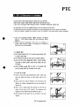
5. Construction
The KTE TCT type thruster unit is designed to give controlled thrust to port or to starboard
by varying the pitch of the propeller blades by remote control from bridge.
5.1 C.P.P System
A constant speed, non-reversing prime mover is connected via a SF coupling to the thruster
input shaft.
This vertical, or fore-and-aft, drive is changed into a horizontal athwartships drive to the
hollow propeller shaft by spiral bevel gears.
The propeller blades are hydraulically controlled by a servomotor situated in the hub body and
the axial forces exerted are transmitted to blades by a crosshead and crank ring.
5.2 Bearings
The input drive and propeller shafts are rigidly mounted on accurately located roller bearings.
The bearings are dimensioned to ensure a very long trouble free life in service.
5.3 Hub
The propeller hub is flange mounted on the propeller shaft and contains a crosshead which sets
the pitch of the propeller blades via sliding blocks and crank ring.
The position of the crosshead is hydraulically controlled by hydraulic oil through OT tube and
OD box.
5.4 Blades and Blade Seals
The propeller blade palm seals prevent the ingress of sea water into the hub or the leakage of
oil from the hub.
In order to facilitate rapid servicing and to reduce the time spent in dry dock, should a blade or
blade seal be damaged, arrangements have been made which allow individual blades to be
removed with the thruster unit sit in the tunnel.
5.5 Lubrication
Lubrication of the spiral bevel gears and roller bearings is effected by flooding the gear housing
with oil which is held at a slightly higher pressure than the external water pressure by means
of a separate header tank thus preventing the ingress of sea water should shaft or blade seals
leak.
5.6 Controls
The standard electrical control system provides from the bridge.
Propeller blade pitch position is mechanically feedback to the control system.
- 4-
The pitch feedback potentiometer and its driving sprocket gear are contained in the feedback
unit, which is mounted on the motor stand and is connected to the pitch position indicator rod
which protrudes from the gear housing flange.
The control and feedback potentiometer from a balanced sprit phase closed loop, feeding a high
gain amplifier and phase detecting network.
Movement of the control potentiometer presents an error signal at the amplifier input, this
signal is amplified and operates the phase detecting network which feeds a control signal to the
solenoid valve, directing the oil to the correct side of the servomotor cylinder(cross head) which
controls the pitch of the propeller blades.
The electrical balance is restored by the corresponding movement on the feedback
potentiometer.
The system gives fine control of the pitch setting, and any deviation caused by external forces
is automatically corrected.
In addition, this control system provided automatic load control (ALC) system which consists of
PI control, load setting function and electric current signal.
The electric current signal is supplied from the CT located at starter panel.
It has function that the blade angle is automatically reduced to protect the main motor overload.
The reducing action is achieved when the current signal is reached to the preset level which
corresponds to the rated load of motor.
The action is automatically reset when the load is decreased.
5.7 Pitch to zero system
During voyage of the vessel, sometimes the propeller is rotated by the tide ( the seawater
coming into the thruster tunnel ) and the pitch is moved out of the zero position.
In this situation, the hydraulic pump automatically will be started and the pitch is kept in zero.
When blade angle returns to zero position, hydraulic pump and solenoid valve will be stopped
after preset time.
This mode is operated independently from normal mode by pushing of this mode select button
on W/H control panel.
Other unrelated lamps except followings shall not be caused under zero pitch mode.
1) Ind. lamp of zero pitch mode
2) Ind. lamp of blade neutral
3) Ind. lamp of hyd. pump run
4) Ind. lamp of acting solenoid valve
5) Alarm lamps
- 5-
6. Materials
Propeller
Hub
Gear Housing
Bearing Housing
Propeller shaft
Crank ring
Cross head
Drive shaft pinion
Spiral bevel wheel
Blade bolt
Hub flange bolt
Duct
: CAC703(A1BC3)
: CAC703(A1BC3)
: FCD450
: FCD450
: SF590A
: SCM435
: SCMn2B
: SNCM420
: SNCM420
: C6191BF(ABBF2)
: SUS630
:GRADE A
: & SUS316L
(Ni-Al-Bronze)
(Ni-Al-Bronze)
(Graphite Iron Casting)
(Graphite Iron Casting)
(Carbon Steel Forging)
(Chromium Molybdenum Steel)
(Carbon Steel Casting)
(Chromium Nickel Molybdenum Steel)
(Chromium Nickel Molybdenum Steel)
(Copper-Alloy Rods)
(Stainless Steel)
(Hull Construction Steel)
(Stainless Steel) in way of blade
7. Designed Mass
Stem Thruster
Bow Thruster
Remark
Thruster assembly
abt.
9500 kg
abt.
7,750 kg
exclude main motor
Hydraulic pump unit
abt.
140 kg
abt.
140 kg
dry condition
Header tank
abt.
70 kg
abt.
70 kg
dry condition
Hyd. pump starter
abt.
80 kg
abt.
80 kg
8. Painting Schedule
Thruster body — • Seawater side
- HEMPELs ZINC 1536
(The other paints are to be carried out by shipyard.)
(MAKER : HEMPEL'S MARINE PAINT)
Duct
• Inboard side
- MUNSELL 10 GY 8/4
• Seawater side
- HEMPELs ZINC 1536
(The other paints are to be carried out by shipyard.)
(MAKER : HEMPEL'S MARINE PAINT)
• Inboard side
- HEMPELs ZINC 1536
(The other paints are to be carried out by shipyard.)
(MAKER : HEMPEL'S MARINE PAINT)
30/fflixlcoat
30/zmxlcoat
30/Æi*lcoat
Hydraulic pump unit —
MUNSELL 10 GY 8/4
Header tank
MUNSELL 10 GY 8/4
Motor stand
MUNSELL 10 GY 8/4
Follow up Transmitter
Hyd. pump starter & Local control box
MUNSELL 7.5 BG 7/2
W/H and both wing controller
N3.0 Semi-Polished (Maker Standard)
N7.5 (Light grey)
- 6-
9. Inspection and Test
The inspection items are as follows :
(1) Material test
(2) Dimension check of propeller blades and shafting part
(3) Pressure test
(4) Appearance check
Shop test
(5) Running test
Shop test
(6) Operation test
Shop test
10. Commissioning
1 (one) Service Engineer for 7 days (1 visit) for start up and commissioning including traveling
and lodging cost.
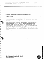
11. Guarantee
Guarantee for 13 months after the start of ship's service, latest 13 months after delivery exworks against any defect breakdown by repairing or replacing, free of charge, if it is proved to
from the defect of material or defective designing or workmanship.
However, non-guaranteed against any accident by force majeure or wearing, or mishandling.
Besides, please be advised any indirect expenses caused by any accident to the system are out of
guarantee.
<The end)
- 7-
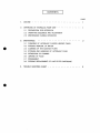
CONTENTS
PAGE
CHAPTER I
OUTLINE
1
CHAPTER I!
SPECIFICATION
2
CHAPTER III
STRUCTURE & OPERATION
4
1. PINION DRIVE SHAFT SUB. ASSEMBLY
2. PROPELLER SHAFT SUB. ASSEMBLY
3. GENERAL ASSEMBLY
4. GENERAL ARRANGEMENT
5. HYDRAULIC PUMP UNIT
6. HEADER TANK
CHAPTER IV
PROCEDURE OF OPERATION
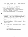
1. ROUTINE OPERATION
1.1 BEFORE PRIME MOTOR TO BE OPERATED
1.2 WHEN PRIME MOTOR TO BE OPERATED
1.3 WHEN PRIME MOTOR TO BE STOPPED
1.4 WHEN THRUSTER IS NOT IN USE
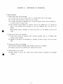
2. DISORDER AND CAUSE
CHAPTER V
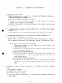
PROCEDURE OF ASSEMBLY
1. PINION DRIVE SHAFT SUB. ASSEMBLY
2. PROPELLER SHAFT SUB. ASSEMBLY
3. OD BOX ASSEMBLY
4. PROPELLER HUB ASSEMBLY
5. PROPELLER SHAFT AND PROPELLER HUB ASSEMBLY
6. ASSEMBLY INTO GEAR HOUSING
7. OIL PIPE AND FEEDBACK DEVICE
8. SET UP IN DUCT
9. CONNECTION OF SF COUPLING
CHAPTER VI
PROCEDURE OF DISASSEMBLY
13
1. PROPELLER BLADE
2. PROPELLER SHAFT SUB. ASSEMBLY
3. PINION DRIVE SHAFT SUB. ASSEMBLY
CHAPTER VII
MAINTENANCE AND INSPECTION
1. PERIODICAL MAINTENANCE SERVICE
2. MAINTENANCE STANDARD OF COMPONENT PARTS AND OIL
3. OIL AND RESIN
4. MAINTENANCE STANDARD OF LUBRICATING OIL
15
CHAPTER
I
OUTLINE
KTE-Nakashima side thruster model TCT-220/200 is electric-hydraulic control with
hydraulic
cylinder in the inside of the thruster, which provides excellent controllability, safety and longlife.
This model consists of
1. Propeller Hub Sub. Assembly
(Propeller Blades, Hub Body, Piston, Crank Ring, Crosshead, Blade Bolts, Dowel Bolts, Sliding
Shoe, Piston Seal, etc.)
2. Propeller Shaft Sub. Assembly
(Propeller Shaft, Crown Wheel, Crown Wheel Hub, Bearing Housing, Protection Plate, Bearings,
Spacer, Shaft Sealing Device, etc.)
3. Pinion Drive Shaft Sub. Assembly
(Pinion Drive Shaft, Bearing Housing, Bearings, Seal Housing, Oil Seals, Spacer, etc.)
4. OD Box and Feedback Device
(OD Box(lnside), OD Box(Outside), Bearings. OT Tube, Rubber Hose, Roller Chain, Sprocket
Idler, Arm, Bracket, Feedback Rod, etc.)
5. Gear Housing Assembly
(Gear Housing, Pipes, Plugs, Stay, etc.)
6. Power Transmission Equipment
(SF Coupling Hub, Grid Member, Cover, etc.)
7. Hydraulic Power Unit
(Suction Filter, Electric Motor, Hydraulic Pump, Relief Valve, Solenoid Valve, Check Valve, Flow
Regulator, Pressure Gauge, Pressure Switch, etc.)
8. Header Tank
(Level Switch, Oil Level Gauge, etc.)
9. Remote Control System
(Feedback Box, Pitch Control Lever, Control Position Demand Push Button, Control Mode
Change Over Push Button, Thruster Driving Push Button. Indicator Lamps, Alarm Lamps, etc.)
- 1-
CHAPTER II
SPECIFICATION
1. Driving Motor
Bow Thruster
Stern Thruster
Model
3 Phase Induction Motor
3 Phase Induction Motor
Output
1400kW, AC 6,600V 30
60Hz 6P
1050kW. AC 6,600V 30
60Hz 6P
No of Revolution
1187 rpm
1185 rpm
Remark
2. SF Coupling
Type
Bow Thruster
Stern Thruster
Remark
PTC-1130-H
PTC-1120-H
PT Coupling Co. Ltd.
Bow Thruster
Stern Thruster
Remark
SC2A-280
SC2A-260
Blohm+Voss
Bow Thruster
Stern Thruster
Remark
3. Shaft Sealing Device
Type
4. Propeller
Model
TCT-220
TCT-200
Diameter
2200 mm
2000 mm
Propeller Speed
275.6 rpm
303.3 rpm
Forward skewed Type
Turning Direction Counter-Clockwise Looking in Propeller
No. of Blade
4
Pitch
0
Material
CAC703CAIBC3)
Control System
Electric-Hydraulic Control
5. Hydraulic Power Unit
Change Over Oil Pump
Bow Thruster
Stern Thruster
Operations (Electric Motor)
5.5 kW x 4P
5.5 kW x 4P
Revolution
1760 rpm
1760 rpm
Continuous Output Pressure
100 kgf/cm
Continuous Output Flow
22.9L/min
2
1 00
kgf/cm2
22.9L/min
- 2-
Remark
6. Head Tank
Capacity
Accessory
Bow Thruster
Stern Thruster
85L
85L
Remark
Filter, Level Switch, Air Breather, Level Gauge etc.
7. Extent of Change Over
Bow Thruster
Stern Thruster
Piston Stroke (Maximum)
abt. + 56.0 mm
abt. ± 50.0 mm
Mechanical Blade Angle (Maximum)
abt. ± 25.8°
abt. ± 25.7°
- 3-
Remark
CHAPTER III
STRUCTURE AND OPERATION
KTE-Nakashima Side Thruster Model TCT-220/200 has such mechanism that with pitch control
lever, pitch control push button equipped in wheel house control panel, and both wing control
panel being operated solenoid valve in hydraulic pump unit is operated, the oil transferred from
hydraulic pump is delivered into OD box in the inside of the thruster, and the oil is transferred to
cylinder through inner bore of prop, shaft or OT tube.
shaft and cross head.
Cylinder is made up of piston, prop,
The movement of cross head is transmitted to sliding shoe and crank
ring successively, and then propeller is operated.
feedback rod through OT tube,
arm and roller
The movement of propeller is transmitted to
chain, the
movement is transmitted
to
potentiometer in feedback system, and then propeller pitch is indicated in the indicator in wheel
house control panel and both wing control panel.
The inside of the thrust unit is filled with lubricating oil, and is always supplied with a little higher
head pressure than that of seawater. The lubricating oil is connected to header tank, and if oil
leaks, oil level in header tank will decrease and alarming will be made with level switch equipped
in header tank.
1. Pinion Drive Shaft Sub. Assembly ("G. A. OF THRUST UNIT" DWGNO. KJ(I)0000-***-*)
Rotation transmitted from driving motor will be transmitted through SF coupling(600) to pinion
drive shaft(8), the rotation is transmitted to crown wheelO), this pinion drive shaft being
geared with crown wheel.
Thrust load and radial load produced in the rotation are
supported with self-aligning roller bearing(61), tapered roller bearing(62) and thrust self
-aligning roller bearing(63).
The inside of gear housingd) filled with lubricating oil.
Oil seal(82) and O-ring(85) are used for preventing lubricating oil from leaking, moreover,
V seal(81) is used against dust coming into oil seal part.
2. Propeller Shaft Sub. Assembly ("G. A. OF THRUST UNIT" DWGNO. KJ(I)0000-***-*)
The rotation transmitted from pinion drive shaft(8) is transmitted to crown wheelO), crown
wheel hub(10), key(33) and propeller shaft(7) successively.
Crown wheel, crown wheel hub,
propeller shaft, liner(11-1) and protection plate(15) are rotated, however, bearing housing(13),
mounting plate(12) and shaft sealing device(11) which are fitted to gear housingd), are not
rotated.
The thrust load produced in propeller rotating, the thrust load produced in crown wheel
rotating and radial load of propeller, propeller shaft and so on are supported with tapered
roller bearing(58) and thrust self-aligning roller bearing(59).
propeller shaft is supported with self-aligning roller bearing(GO).
Besides, radial load of
Shaft sealing device(ll), O-ring(87)(100) and gasket(11-80)(11-81) are used for preventing
lubricating oil from leaking and preventing ingress of seawater.
with protection plate, liner and O-ring(88) against being rusted.
Propeller shaft is protected
Intermediate cover(17) is
for preventing propeller shaft from being winding with ropes or seaweeds or marine plants.
_ 4 _
3. General Assembly ("G. A. OF THRUST UNIT" DWGNO. KJ(I)0000-***-*)
Propeller shaft(7) and hub body(2) are secured with hub flange bolt(27), and knock pin(31),
and as propeller shaft is rotated, hub body also is rotated.
Blade(3) is secured to crank ring(6) with blade bolt(25) and dowel bolt(26), and as crank ring
is rotated, blade is also rotated, and then pitch is controlled.
Crank ring has groove in eccentricity of rotation axis, and the groove is in cross head(5) pin
part together with sliding shoe(28).
The pin has the function of changing linear movement
of crank ring into rotating movement.
OD box(inside)(21) is connected with propeller shaft, OD box(inside) and propeller shaft are
rotated, however, OD box(outside)(22) is not rotated with key part of bracket(42) against
revolution.
OT tube(20) is connected through hollow part of propeller shaft to cross
head in hub body.
The movement of cross head is transmitted directly to crank ring and blade.
There is arm(43) on OT tube, the movement of OT tube is feedbacked on the outside of the
thruster through roller chain(49) and feedback rod(44).
Accordingly, the movement of this
feedback rod up and down will be the indication of blade angle.
The inside of gear housingd) and hub body are filled with lubricating oil, O-ring(85)(86)(87)
(88)(89)(90)(100) and packing(99), etc. are used for preventing lubricating oil from leaking and
preventing ingress of seawater.
The oil is transferred into OD box through rubber hose(106)
from A, B port of hydraulic pump unit.
Besides, lubricating oil is kept with a little higher pressure than that of seawater due to head
pressure always given with piping arrangement of header tank to piped05).
4. General Arrangement
("G. A. OF THRUST UNIT"
DWGNO.
KJ(I)0000-***-*,
"THRUSTER
ARRANGEMENT" DWGNO. KJ(1)5000-***-*. "FEEDBACK UNIT ASS'Y" DWGNO. KJ(I)7000-***-*)
Side thruster(501) is installed in duct(502) with hex. hd. bolt(513).
Contact face of side
thruster and duct is provided with 0-ring(84) which prevents ingress of seawater.
There is bracket for feedback box of motor stand(504) on duct on which feedback box(701)
is mounted.
Sprocket of feedback box is connected, through roller chain(704)(716) and
chain bolt(717) with feedback rod(44).
The actual propeller pitch angle and pitch
graduations are adjusted with chain bolt, and locked with hex. hd. nut of chain bolt.
Hand pump(506) is utilized in case the oil in the thruster shall be taken out into the outside.
In case the inside of thruster shall be checked with cover(41) and end cover(19) open, in drydocking of the vessel.
- 5-
5. Hydraulic Pump Unit (DWGNO. SB-E202-*. SB-E302-*)
The oil transferred from hydraulic pump(2) goes through check valve(8) and is set to 9.81 MPa
(100 kgf/cm2) at relief valve(5) and enters solenoid valve(6).
When propeller pitch is not
controlled, that is, there is no electric current on coil of solenoid valve, the oil transferred
from the pump will be returned to tank with no load.
When there is electric current on any solenoid valve, the oil from the pump will be hydraulic
oil in A or B direction.
As A, B ports and the thruster are connected with piping, the oil
transferred will come into the cylinder of the inside of the thruster, and pitch will be
controlled.
For checking set pressure 9.81 MPa (100 kgf/cm2), propeller pitch shall be changed to fullstarboard or full-port with manual operation of solenoid valve, and adjustment shall be made
with the screw of relief valve, pressure gauge(9) being carefully watched. When the screw is
turned to right, the set pressure will increase, and to left, it will decrease.
After the setting, propeller pitch shall be changed to O(zero) degree without fail.
After the
setting, the indicator of the pressure gauge will be down at less than 1.96 MPa (20 kgf/cm2).
Pitch changing speed adjustment shall be made with screw of flow regulator(7).
When the
screw is turned to right, the pitch changing speed will be fast, and to left, it will be slow.
When the hydraulic pressure of the oil delivered by hydraulic pump is decreased (0.4 MPa
(4 kgf/cm2) or lower), signal will be given by pressure switch(4) and then warning lamp of
"HYD. PUMP LOW PRESS" will be lit on wheel house control panel.
Besides, in case electric lines are in disorder, and solenoid valve does not operate, the oil
from the pump will be delivered to A or B direction with the spool of solenoid valve operated
where rod is directly pushed in solenoid valve, and then propeller pitch can be operated.
6. Header Tank (DWGNO. SB-E102-*)
Header
is open
tank is
lower),
LEVEL"
tank is for the supplying the thruster with gravity oil.
Stop valve on gravity oil line
at normal operation condition.
Level switch(3) is for alarming in case the oil in the
below the fixed level(abt. 85 L).
When oil is decreased in quantity(abt. 45 L or
signal will be given by level switch(3) and warning lamp of "HEADER TANK LOW
will be lit on wheel house control panel.
The tank shall be 85 L of oil inside.
- 6-
CHAPTER IV
PROCEDURE OF OPERATION
1. Routine Operation
1.1 Before prime motor to be operated.
(1) To confirm that oil level in header tank is to standard level with oil level gauge.
(2) To confirm that stop valve on gravity oil line is open.
(3) To confirm that lamps of indicators are in order with electric power source switched on
in control console in wheel house.
(4) With hydraulic pump switched on, hydraulic pump to be operated for 5—10 minutes in
order to test propeller pitch controlling to port and starboard side, and set to
"0"
(ZERO).
While hydraulic pump is operated, to confirm that there is no oil leakage at joint part of
piping.
1.2 When prime motor to be operated.
(1) Prime motor should be operated after checking propeller pitch to "0"(ZERO) with
hydraulic pump operated.
(2) Attention to be paid to oil temperature in hydraulic oil tank so that it will not be over
65TC.
1.3 When prime motor to be stopped.
(1) Prime motor should be stopped after propeller pitch set to "0"(ZERO).
(2) Hydraulic pump must be stopped after stopped prime motor.
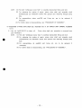
1.4 When thruster is not in use.
(1) When thruster is not in use, control source switch shall be changed to off position
certainly.
- 7-
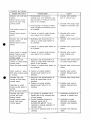
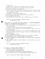
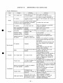
2. Disorders and Causes
Disorder with Control
Disorder with only lever
control.
(wheel house control
panel and both wing
control panel)
Push button control is
normal.
(wheel house control
panel)
Disorder with only push
button control,
(wheel house control
panel)
Checking Items
1. Disconnection of wiring at
amplifier part, and slackness and
disconnection of wiring at control
lever to be checked.
2. Disconnection of wiring at blade
angle feedback transmitter part to
be checked.
3. Contact of control mode change
over switch to be checked.
1. Slackness and disconnection of
wiring at control push button to
be checked.
2. Contact of control push button to
be checked.
Causes
1. Disorder with amplifier
part or control lever.
2. Disorder with blade angle
feedback transmitter part.
3. Disorder with control
mode change over
switch.
1. Disorder with control push
button.
2. Disorder with control push
button.
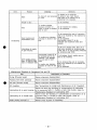
Lever control is normal, 3. Contact of control mode change
over switch to be checked.
(wheel house control
panel and both wing
control panel)
Disorder with only
1. Slackness and disconnection of
wiring at control lever and push
control on wheel house
control panel,
button to be checked.
(lever and push button) 2. Contact of control push button to
be checked.
3. Disorder with control
mode change over
switch.
Lever control in wing
3. Contact of control position
demand push button to be
both wing control panel
is normal.
checked.
3. Disorder with control
position demand push
button.
Disorder with only
control on both wing
control panel
Operation at wheel
house control panel is
normal.
(lever and push button)
Disorder with lever
control and push
button control,
(wheel house control
panel, both wing
control panel)
1. Slackness and disconnection of
wiring at control lever to be
checked.
2. Contact of control position
demand push button to be
checked.
Oil quantity of operation oil in
header tank to be checked with
oil level gauge.
Control hydraulic pressure in
hydraulic pump unit is
9.81MPa(100 kgf/cnf). TO be
checked by manual operation of
solenoid valve.
The coil of solenoid valve is to be
checked.
- 8-
1. Disorder with control lever
or control push button.
2. Disorder with control push
button.
1. Disorder with control lever.
2. Disorder with control
position demand push
button.
1. Insufficient operation oil
quantity in header tank.
2. Insufficient control
hydraulic oil pressure.
Disorder with hydraulic
pump.
3. Disorder with solenoid
valve.
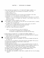
CHAPTER V
PROCEDURE OF ASSEMBLY
1. Pinion Drive Shaft Sub. Assembly ("G. A. OF THRUST UNIT" DWGNO. KJ(I)0000-***-*)
1.1 Pinion drive shaft(8) stood and self-aligning roller bearing(61) is shrink fitted.
1.2 Retainer ring(72) is set in.
1.3 Bearing housing(14) is set in.
1.4 Tapered roller bearing(62) and thrust self-aligning roller bearing(63) is shrink fitted.
1.5 Spacer(36) is set in, lock washer(71) and lock nut(68) are set in.
1.6 Spacer(37) is set in, seal housing(16) and bearing housing is fitted with hex. hd. bolt(121).
(Thickness of spacer to be adjusted with clearance of 0.01—0.05mm toward axis of
tapered roller bearing.)
1.7 Seal housing is removed, spring(39) is set in spacer.
1.8 Oil seal(82) is set in seal housing. (Oil seal outer face to be spread silicone, in between
the two oil seals to be greased up.)
1.9 0-ring(86) is set in bearing housing, seal housing is fitted with hex. hd. bolt(121).
(Hex. hd. bolt to be coated with locking stuff.(Lock Tight 242))
1.10 V seal(81) and 0-ring(83) are set in shaft liner(40).
1.11 Shaft liner is fitted and set with set screw(127).
NOTE : (1) 0-ring and lip part of V seal to be greased up.
(2) Each bolts to be tightened with the designated torque.
(3) Plug(102) to be tightly screwed with seal tape onto seal housing.
2. Propeller Shaft Sub. Assembly ("G. A. OF THRUST UNIT" DWGNO. KJ(I)0000-***-*)
2.1 Crown wheel(9) is set in crown wheel hub(10) with knock pin(31) and hex. hd. bolt(119).
Knock pin is set by set screw(126).
2.2 Propeller shaft(7) is stood up with hub body underneath.
2.3 Protection plate(15), liner(11-1) and gasketd 1-81) to be set on propeller shaft with hex.
hd. bolt(11-10).
2.4 Liner outer face to be greased up, shaft sealing device(11) and gasketd 1-80) are set in.
2.5 Tapered roller bearing(58) to be shrink fitted on propeller shaft.
2.6 Bearing housing to be set in.
2.7 Shaft sealing device assembly to be set in bearing housing(13) with hex. hd. bolt(11-7).
2.8 Spacer(35) and thrust self-aligning roller bearing(59) is set in. (Thickness of spacer to be
adjusted with clearance of 0.01—0.05mm toward axis of tapered roller bearing.)
2.9 Thrust self-aligning roller bearing is removed, spring(38) is set in bearing housing.
2.10 Key(33) to be set on propeller shaft, and crown wheel assembly is set in.
2.11 Lock washer(70) and lock nut(67) is set in.
2.12 Self-aligning roller bearing(60) is shrink fitted to propeller shaft, and set with retaining
ring(72).
- 9-
NOTE : (1) Handling of shaft sealing device refer to "Instruction Manual for Propeller
Shaft Sealing Device(TYPE : SC2A)".
(2) 0-ring and its groove to be greased up.
(3) Locking wire to be used.
(4) Each bolts to be tightened with the designated torque.
3. OD Box Assembly ("G. A. OF THRUST UNIT" DWGNO. KJ(I)0000-***-*)
3.1 Deep groove roller bearing(64) is shrink fitted on OD box(inside)(21).
3.2 After lubricating oil to be spread on inside of OD box(inside), OD box(outside)(22) is set in.
3.3 Deep groove roller bearing(65) is set in, and set with retainer ring(74).
3.4 Piston seal(79) and slide ring(80) are set in OD box(inside).
3.5 90 elbow adapter(107) to be tightly screwed with seal tape onto OD box(outside).
NOTE : (1) Lubricating oil to be spread on piston seal.
4. Propeller Hub Assembly ("G. A. OF THRUST UNIT" DWGNO. KJ(I)0000-***-*)
4.1 Crank ring(6) is set in hub body(2), and O-ring(92) and blade seal ring(30) are set in.
4.2 Propeller blade(3) is fixed to crank ring with blade bolt(25) and dowel bolt(26). (Blade bolt
and dowel bolt to be coated with locking stuff(Molycoat) and to be tightened with the
designated
torque(Bow:835N-m(85kg-m)/Stern:667N-m(68kg-m)). O-ring(91)
to be set
in
blade bolt and dowel bolt. Groove of crank ring to be placed upward(gear housing side).
4.3 Piston seal(78) and 0-ring(89) are set in piston(4), and set into hub body with soc. hd.
cap bolt(114).
4.4 Sliding shoe(28) to be put in pin of cross head(5), and set down in hub body from top.
4.5 Turning propeller blade, sliding shoe is slide fitted into groove of crank ring. (Four(4)
blades are fitted as well simultaneously.
Special care should be taken and piston seal
should be with damage.)
4.6 0-ring(93) is fixed on OT tube(20), and set into cross head with hex. hd. bolt(117).
NOTE :
(1) Propeller blade, crank ring, sliding shoe, blade bolt, dowel bolt and cross
head are set in each reference mark.
(2) Each slide face to be so clean without any dust and scratch which should
not exist.
(3) Special care should be taken and sliding shoe should be smoothly slide set
into cross head groove without any means of force fitting.
(4) Locking wire to be used.
(5) Blade bolt and dowel bolt to be fixed with locking bar(132).
- 10 -
5. Propeller Shaft and Propeller Hub Assembly ("G. A. OF THRUST UNIT" DWGNO. KJ(I)0000-***-*)
5.1 Knock pin(31) is set in hub body(2).
5.2 Piston seal(78) is set in propeller shaft(hub body side), and set into cross head(5) in hub
body. (O-ring(88) to be put into the contact part of propeller shaft and hub body.)
5.3 Propeller shaft and hub body are fitted with hub flange bolt(27). (Hub flange bolt to be
coated with locking stuff(Molycoat) and to be tightened with the designated
torque
(Bow:1.1kN-m(111kg-m)/Stern:834N-m(85.1kg-m)). 0-ring(98) to be set in hub flange bolt.)
NOTE : (1) 0-ring and its groove to be greased up.
(2) Hub flange bolt to be fixed with locking bar(133).
6. Assembly into Gear Housing ("G. A. OF THRUST UNIT" DWGNO. KJ(I)0000-***-*)
6.1 Distance washer(23) is fitted to gear housing(l) and pinion drive shaft sub. assembly is set
in, using 0-ring(85) and hex. hd. bolt(112).
6.2 Distance ring(24) is fitted and propeller shaft sub. assembly and propeller hub assembly is
set in, using 0-ring(87) and soc. hd. cap bolt(111)(124).
6.3 OD box assembly is set in propeller shaft, using 0-ring(94) and soc. hd. cap bolt(116).
6.4 Bracket(42) is set in gear housing with soc. hd. cap bolt(120). (Key part of bracket is set
in groove of OD box(outside).
Sprocket idler(46) idler pin(47), U-nut(48)
and plain
washer(137) is set in bracket before assembling.)
6.5 Tapered roller bearing(66), spacer(55) and arm(43) set in OT tube(20), and locked with
hex. slotted and castle nut(57) and split pin(56). (Thickness of spacer to be adjusted with
clearance of 0~0.03mm toward axis of tapered roller bearing.)
6.6 Guide rod(45) is screwed on bracket. (Screw part of guide rod to be coated with locking
stufULock Tight 242))
6.7 Intermediate cover(17) is fixed to bearing housing(IS) with hex. hd. bolt(115), and locked
with hex. hd. bolt(18).
NOTE : (1) Gear tooth matching and backlash to be adjusted to thickness of distance
washer(23) and distance ring(24).
Backlash (Bow:0.46-0.82mm/Stern:0.44—0.78mm) at outer diameter of P.C.D.
(Bow:200.2mm/Stern:203.5).
(2) The matching work of gear tooth to be carefully carried out watching from
peep hole.
(3) 0-ring and its groove to be greased up enough.
(4) Locking wire to be used.
(5) Each bolts to be tightened with the designated torque.
7. Oil Pipe and Feedback Device ("G. A. OF THRUST UNIT" DWGNO. KJ(I)0000-***-*)
7.1 Plug(103) is set onto the tip of rubber hosed06).
(Plug to be tightly screwed with seal tape.)
7.2 O-ring(97) set in plug, rubber hose is set into gear housing(l), and plug to be tightly
screwed on gear housing.
7.3 Rubber hose is connected with 90 elbow adapter(107) screwed onto OD box(outside)(22).
(Screw part of rubber hose to be coated with locking stuff. (Lock Tight 242), and to be
- 11 -
tightly screwed.)
7.4 0-ring(97) is set in plug(104), and to be tightly screwed on gear housing.
7.5 Pipe(105) is fixed in gear housing, using clip(108) and hex. hd. bolt(118).
7.6 Bush(51) and Oring(96) is set in gear housing.
7.7 Feedback rod(44) set with roller chain(49) is threaded through a hole of bush, and roller
chain is connected with arm(43) through sprocket idler(46) fixed in bracket(42), using
chain bolt(50) and hex. nut(53).
7.8 0-ring(95) is set in bush(51), and plate(52) is set in.
7.9 Point ring(134) and chain bolt(54) is screwed with the tip of feedback rod.
7.10 Pitch gauged 09) is fitted on plate.
7.11 End cover(19) is fitted to gear housing, using O-ring(90) and soc. hd. cap bolt(113).
NOTE : (1) O-ring and its groove to be greased up enough.
(2) Locking wire to be used.
8. Setup in Duct ("G. A. OF THRUST UNIT" DWGNO. KJ(I)0000-***-* "THRUSTER ARRANGEMENT"
KJ(I)5000-***-*, "FEEDBACK UNIT ASS'Y" KJ(I)7000-***-*)
8.1 Gear housing to be set in the duct(502) and fitted on the mounting plate part of duct
with hex. hd. bolt(513).
(O-ring(84) to be put into the contact face of gear housing and duct.)
8.2 The foot part of gear housing to be fitted with stay(505) the stay and duct to be
connected by welding.
8.3 Cover(41) for peep hole is fitted with soc. hd. cap bolt(125). (Packing(99) enough coated
with sealing stuff (Three Bond 1102 or equal), to be put in the contact face of gear
housing and cover.)
8.4 Each pipe arrangement is provided.
8.5 Motor stand(504) is fitted on the mounting plate part of duct with hex. hd. bolt(515).
8.6 Feedback box(701) is set on bracket for feedback box of motor stand.
8.7 Sprocket of feedback box and feedback rod(44) are connected with roller chain(704)(716)
and chain bolt(717).
8.8 After adjustment propeller pitch angle completed, to be locked with hex. nut of the
chain bolt.
NOTE : (1) O-ring and its groove to be greased up enough.
(2) Locking wire to be used.
9. Connection of SF Coupling (DWGNO. KJ(I)6000-***-*)
9.1 Key(34) is set in pinion drive shaft of thruster.
The coupling hub(601) is mounted(shrink fitted).
9.2 The motor output shaft is mounted with the coupling hub(602) as well.
9.3 To be connected the both hubs with grid member(603), cover(604), bolt and nut.
NOTE : (1) For detail, see "HOW TO HANDLE of SF COUPLING".
- 12 -
CHAPTER VI
PROCEDURE OF DISASSEMBLY
1. Disassembly of Propeller Blade
1.1 Draining lubricating oil in the thruster ("G. A. OF THRUST UNIT" DWGNO. KJ(I)0000-***-*,
"THRUSTER ARRANGEMENT" KJ(I)5000-***-*)
(1) Stop valve on gravity oil line applied to be closed.
(2) PlugdOD to be removed and the lubricating oil in gear housingd) to be drained,
(possible to draw inboard by hand pump(506)).
(3) PlugdOD to be removed.
And then lubricating oil in hub body(2) to be drained with
the hole down.
1.2 Disassembling blade bolt(25) and dowel bolt(26) ("G. A. OF THRUST UNIT" DWGNO.
KJCOOOOO-***-*)
(1) Locking bard 32) to be removed and disassembling to be made with use of spanner.
1.3 Disassembling propeller blade ("G. A. OF THRUST UNIT" DWGNO. KJ(I)0000-***-*)
(1) Prop, blade for dismounting to be to the top.
(2) Prop, blade to be lifted for taking the protrude (5 mm) on the flange of prop, blade off.
(3) Prop, blade to be taken out of duct. (Blade mass : Bowrabt. 178kg/Stern:abt. 133kg)
NOTE : Matters to be attended to for re-assembling
(1) Re-assembling procedure for prop, blade to be just the reverse of
the
disassembling procedure.
(2) Each parts to be assembled so that each marking or number will agree without
any flaw remained on each parts.
(3) 0-rings to be renewed with the spare.
(4) After prop, blade mounted, lubricating oil to be applied and air extraction to be
made with plug(IOI).
And when lubricating oil flow over the hole, to be
firmly fastened with plug.
(5) Locking bar(132) to be used without fail.
(6) Air extraction of the inside of gear housing to be effected with plug (102)
slackened till oil will come out, where lubricating oil to be applied in header
tank.
2. Disassembly of Propeller Shaft Sub. Assembly ("G. A. OF THRUST UNIT" DWGNO. KJ(I)0000***—*)
2.1 End cover(19) is removed.
2.2 Bracket(42) and arm(43) is removed.
2.3 Intermediate cover(17) is removed.
2.4 Soc. hd. cap bolt(111)(124) is taken off.
Propeller shaft sub. assembly is removed from
gear housingd).
- 13 -
NOTE : (1) Part with "withdrawal screw hole" is carefully dismounted fitting jack bolt.
(2) For releasing the mating of gears, pinion drive shaft and propeller shaft
simultaneously are withdrawn slowly with special care watching through peep
hole.
(4) For reassembling, piston seal(78) and Oring etc. are to be replaced
if
necessary.
(5) For further detail of disassembling, see "PROCEDURE OF ASSEMBLY".
3. Disassembly of Pinion Drive Shaft Sub. Assembly ("G. A. OF THRUST UNIT" DWGNO. KJ(!)0000
-***-*)
3.1 Hex. hd. bolt(112)021) is taken off.
Pinion drive shaft sub. assembly is removed from
gear housingd)
NOTE : (1) Part with "withdrawal screw hole" is carefully dismounted fitting jack bolt.
(2) For releasing the mating of gears, pinion drive shaft and propeller shaft
simultaneously are withdrawn slowly with special care watching through peep
hole.
(3) For reassembling,
oil
seal(82)
and
O-ring
etc.
are
to
be
replaced
necessary.
(4) For further detail of disassembling, see "PROCEDURE OF ASSEMBLY".
- 14 -
if
CHAPTER VII
MAINTENANCE AND INSPECTION
1. Routine Maintenance :
Daily
Checking
Position
Time
Oil in header tank
To be full up to the top
of oil level gauge.
Servicing
Oil to add if decreased.
To check if so often decreased.
To check its cause if occurred, to
To check if any abnormal
check if bolt loosened and if grease is
vibration or noise.
off.
To check pressure gauge
Operation the pressure
prescribed in 9.81MPa
To adjust with relief valve.
of hydraulic power unit
(100 kgf/cm2)
SF coupling
Weekly
Monthly
To check each bolt.
Roller chain(704)(716)
Chain bolt(54)(717)
Greasing
Greasing
The tension of the spring
To be exchanged for spare parts.
confirms it fully.
Spring(706)
Feedback rod(44)
Feedback box(701)
Greasing
Greasing
To be greased.
Sprocket gear to be greased.
Hydraulic pump unit
and piping
To check if any oil
leakage in piping joint.
Flange bolt to be tightened up if
eaked.
Packing to be replaced if necessary.
Greasing
To be remove both plugs and insert
übe fitting.
Full with recommended lubricant until
an excess appears at the opposite
lole.
<CAUTION>
Make certain all plugs have been
nserted after lubricating.
SF coupling
SemhAnnually
Shafts
Annually
Bolt to be tightened in prescribed
torque if loosened.
Roller chain to be greased.
3olt to be greased.
SF coupling
Oil in header tank
Thruster body
To check if any crack or If crack or damage found, to be
damage.
replaced with new one.
To be renewed if too dirty.
Standard renewal every dry-docking or
contamination of oil is excessive
To check if dirty.
NAS 11 CLASS or NAS 108 CLASS,
(refer to "Maintenance Standard of
Lubricating Oil")
If leakage found, its leaking section is
To check if leakage from
dismounted and set with new 0-ring
any part of body.
and/or packing.
Renewal of lubricating To check its dirtiness
oil in gear housing
condition.
Dry-docking
To tighten up stop valve of header tanh
line and take out plug(101) at bottom
of gear housing.
Oil in boss to be taken out through
hole of air plug(101).
Propeller blade
To check if any
To be repolished.
deformation, damage and Part of damage and deformation to be
crack etc.
repaired or renewed.
Inside gear housing
Peep hole cover to be
removed and to check if
any damage on gears.
- 15 -
To be renewed if damaged.
When replacing, new gear to be
checked adjusting it's mated
condition and backlash.
Time
Checking
Position
Servicing
To tighten up if loosened.
To check if any looseness To renew if any crack found.
Bolt holes to be puttied up for
or crack.
protecting from seawater.
Bolts
To be renewed.
Anode in duct
Dry-docking
Duct
To confirm whether
To be repaired for welding.
injurious corrosion or
crack is found in welding To be repainted.
part of duct.
Gear housing and
intermediate cover
To be removed the part of corrosion,
and to be repaired by the material for
repair, etc.
To confirm any injurious
corrosion is found in any To be repainted.
Intermediate cover(17) to be
part.
removed and repainted inside and
outside.
To fill oil in header tank, after air in
hub body released by removing plug
(101) and air in gear housing released
by removing plug (102).
Lubricating oil supply
in gear housing
Intermediate cover(17) to
If oil leakage found, sealing ring or
be removed and to be
liner to be renewed.
checked if any leakage
Shaft sealing device
from any part of seal
Bow: (11XSC2A-280) body.
To be removed the part of corrosion,
Stern: (11XSC2A-260)
and to be repaired by the material for
To confirm any injurious
repair, etc.
corrosion is found in any
To be repainted.
part.
2. Maintenance Standard of Component Part and Oil :
Part
Description of Standard
0-ring (Thruster body)
Renew whenever disassembled
Packing (Oil sheet packing)
Renew whenever disassembled
Oil seal (Thruster body)
Renew whenever disassembled
SF coupling
See "Instructions for Install and Maintenance of SF Coupling"
Lubricating oil in gear housing
Lubricating oil in header tank
Shaft sealing device(11)
Renew all when dry-docking or contamination of lubricating
oil is excessive NAS 11 CLASS or NAS 108 CLASS, (refer to
"Maintenance Standard of Lubricating Oil")
Renew every dry-docking or contamination of lubrication oil is
excessive NAS 11 CLASS or NAS 108 CLASS, (refer to
"Maintenance Standard of Lubricating Oil")
Renew every 6 years or necessary
- 16 -
3. Oil and Resin :
Position/Part
Special Oil/Resins
Gear oil
ISO VG 68
Gear housing
Header tank
See Recommended Gear
Quantity require Bow
Gear housing
: abt. 440 L
Header tank
: abt. 85 L
Total
: abt. 525 L
in SF coupling
Grease
(Lithium system)
Quantity require Bow
: abt. 910 g
Liquid packing at oil sheet packing part
Three Bond 1102
(Three Bond Co. Ltd.)
Oil
Stern
340 L
85 L
425 L
Stern
730 g
Thinly coat over
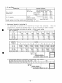
4. Maintenance Standard of Lubricating Oil
The contamination of lubricating oil is measured by milli-pore filter periodically.
When the
contamination is excessive the allowable range of use, the lubricating oil shall be renewed.
(1) Particle in lubricating oil (number of particle in 100ml), count method
CLASS
SIZE OF PARTICLE
tøm)
00
1
0
2
3
4
1,000
2,000
4,000
8.000
1,425
5
5~15
125
250
500
15-25
22
44
89
178
356
712
25-50
50-100
more than 100
4
8
16
32
63
126
253
1
0
2
0
3
1
6
1
11
2
22
4
45
8
SIZE OF
PARTICLE
(/an)
5-15
15-25
25-50
50-100
more than 100
CLASS
7
8
9
10
16,000
2,850
32.000
5,700
1,012
128,000
22,800
4,050
256,000
45,600
506
64,000
11,400
2,025
90
180
360
720
1,440
16
32
64
128
256
6
8,100
11
12
512,000 1 ,024,000
91,000 182,400
16,200
32,400
2,880
5,760
512
1,024
[NEW OILJ
H
TARGET RANGE
WARNING
ALLOWABLE
RANGE OF USE
:
—
=T_W
—
(2) Contaminated substance in lubricating oil (mg/100ml), mass method
108
107
CLASS 100 101 102 103 104 105 106
MASS 0.02 0.05 0.10 0.30 0.50 0.70 1.0 2.0 3.0 4.0 5.0 7.0 10
15
25
NEW OIL
H— H
TARGET RANGE
ALLOWABLE RA NGE OF USE
- 17 -
WARNING
JUN. 2004
SIDE THRUSTER (TCT TYPE) RECOMMENDER GEAR OIL
KTE KTE Co.,
Ltd.
MECHATRONICS DIVISION
NAME
MAKER
IDEMITSU KOUSAN
DAPHNE SUPER GEAR 68
KYGNAS OIL
GEAR OIL ML 68
NIPPON OIL
BONNOK M 68
COSUMO OIL
COSMO GEAR SE 68
JAPAN ENERGY
JOMO REDUCTUS 68
MITSUBISHI OIL
DIAMOND GEAR LUB SP 68
SHOWA-SHELL
SHELL OMALA OIL 68
ESSO
SPALTAN EP 68
MOBIL
MOBIL GEAR 626
GENERAL
GENERAL SP GEAR ROLL 68
TEXACO
MEROPA 68
B.P.
ENERGOL GR-XP 68
GULF
EP LUBRICANT 68
CASTROL
ALPHA SP 68
TOTAL
CARTER EP 68
CALTEX
MEROPA LUBRICANT 68
CHEVRON
NL GEAR COMPOUND 68
<The end>
- 18 -
INSTALLATION MANUAL FOR BOW & STERN THRUSTER
TYPE : SF COUPLING (GRID COUPLING)
MODEL : PTC-1130-H & 1120-H
PT COUPLING Co., LTD.
•TB
r
6. §*} £A) (instruction for Installation)
Coupling^
2|#o| K
H Type Taper Grid Coupling^ ^£* 7||£g}0| ^gO|l4
The performance and life of the coupling depend on how you install and service them.
This page helps you how to assemble the coupling for the best performance and for the trouble free operation.
H Taper Grid Coupling is designed to be operate in either the horizontal or the vertical position without modification.
Taper Grid Coupling^ ^x|e
irzr *K H£|I1 Feeler Gauge (SEfe Dial Gauge) ^ &J°
Simple standard mechanical tools such as wrenches, a
straight edge and feeler gauge or dial guage are required to.
install the Taper Grid coupling.
1. H Type?]
© as- ^§t Ail3ff£
6 3- Oil SealOll Grease!
?• Hubft ShaftOil ?7|£r.
?l|0|*li- ^|T| &
53011
Hub°| TcothfOll Greasel
ftf * S
7(1
1. In case of H type
® Clean all metal parts using nonflammable solvent Lightly coat
seals with grease and place on shaft. Mount hubs on the
shafts.
@ Using a spacer bar, equal in thickness to the normal gap. The
difference in maximum measurements must be not exceed the
angular limit
(D Align so that a straight edge rests squarely on both hubs as
shown fig. And also at 90° interval. The clearance with
dialgauge must not exceed the limit specified in table 21
® After greasing the tooth groove hub, fix the GRID in the same
direction.
PTC PT couplings Co.lTD
(D GridOll Greasef §£s| l^H Oil SealO) Covers)
g t(Ha T 2J£ T)*|O|| *H Gasketf fl|i
Cover °^so)| Sl^ Match Marlo^ §0) t^
• Covert 5H°W.
© Grease fully upon the grid Race oil seals on the hubs,
put gaskets and fasten the cover haves correcty by
bolts.
Couplings] £s| (Coupling disassembly and grid removal.)
Couplings] SSflAlOfe Grid°| 2S|
EEHWS ?|2| H|jJ!f ^0| Grid°| ÖS
HSJc ?rc Coupling2| 5ff Jf ^§0|| lc||5|o| O£0|r4.
Whenever it is necessary to disconnect the coupling, remove the cover halves and grid.
A round rod or screw driver can be convenient tool to remove the grid.
53
(Unit:mm)
Parallel
Misalignment
Angular
Misalignment
GAP
E-3
*?JS 0|^2) 2.x\7\
fe coupling ^r§0|
. The life of coupling is reduced by excess of the limit.
PTC PT couplings Co.LTD
r?ß(Lubrication
and Handing)
You should choose the high qualty lubricant for PTC Taper Grid
Coupling for a good performance and long life.
PTC Taper Grid Coupling^
1. Grese Lubrication
1. Grease £f
Cover
Gridf Hub2f 5|JS $ Greasef
^ Grease ^gfif fsll Greasef
Grease on the grid before assembling covers. Rll up grease
through the lube plugs of the assembled coupling.
2. Supplement and Replacement
Grease
, ££ 240~250A|#
4,OCOA|# A(f ^ Couplings
Every three month Every 240-253 hours operating, you should
add grease. Every 3 months, or every 4,000 hours operating
you should replace all the deteriorated grease.
0\
a Selection
Grease°|
You can choose grease according to the ambient temperature
range in table 5.
^ -l/C 70'CO|Ü
Tables
Common Industrial Lubricants(NYGL Grade #2)
Amoco Oil Co.
Atlantic Richfield co.
Chevron U.S.A Inc.
Cities Service Co.
Conoco Inc.
Exxon Company, USA •
Gulf Oil Corp.
E.F.Houghton & Co.
Impenrial Oil Ltd.
Keystone Div.(Pennwalt)
Mobil Oil Corp.
Phillips Petroleum Co.
Shell Oil Co.
Standard Oil Co.(OH)
Sun Oil Company
Texaco Lubricants
Union Oil Co.(CA)
Valvoline Oil Co.
Amolith Grease #2
Litholene HEP 2
Chevron Dura-Lith EP-2
Citgo HEP-2
EP Conolith #2
Ronex MP
Gulfcrown Grease #2
Cosmolube #2
Esso MP Grease H
#81 Light
Mobilux EP111
IB & RB grease
Alvania Grease #2
Factran #2
Prestige 42
Starplex HD 2
Union Undoba #2
Val-Lith EP #2
Amolith Grease #2
Litholene HEP 2
Chevron Dura-Lith EP-2
Citgo HEP-2
EP Conolith #2
Ronex MP
Gulfcrown Grease #2
Cosmolube #1
Lotemp EP
#84 Light
Mobilux #1
Philube IB & RB grease
Alvania Grease #2
Factran #2
Prestige 42
Multifac EP2
Union Undoba #2
Val-Lith EP #2
• Note: Check with lube manufacture for approved lubricants to use in the food processing industry.
PTC PT couplings Co.LTTJ
•
I
I
•
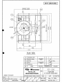
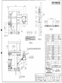
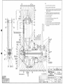
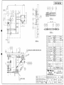
TYPE
SHIPYARD
SHIP NO.
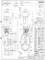
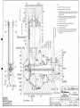
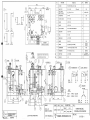
TCT-220
HEADER TANK
OILING PORT(SGP 40A)
DAEWOO SHIPBUILDING & MARINE ENGINEERING CO., LTD.
BOW THRUSTER
TO FILLING POINT IN B/STORE DECK
RETURN (SGP_32A)
H-4437/38/41
BLADE TIP CLEARANCE
DESIGN
17mm
MINIMUM
5mm
SUCTION(SGP 32A)
HYD. PUMP UNIT
APPROX.2020I
OPERATING OIL(STPG370S SchSO 20A)
MOTOR 1400kw
AC 30 6600V 60Hz
SHIPYARD SUPPLY
OPERATING OIL(STPG370S SchSO 20A)
NOMINAL THRUST
obt. 21.4 TON
FEEDBACK UNIT ASS Y
SFCOUPUNGASSY
WASHER(SUS316)
SPRING WASHER
KTE-jf NAKASHIMA
FULL WELDING
KTE CO..LTD.
MECHATRONICS DIVISION
THRUSTER ARRANGEMENT
Main Motor rearranged
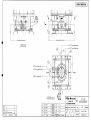
1. REFER TO NEXT PAGE (DWG. No. KJ5100-001-1) FOR PLAN VIEW
2. * MARKED VALVE : SHIPYARD SUPPLY
May 21.2004
KJ5000-001-2
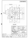
BOW THRUSTER
A PORT
PLAN VIEW
701
FEEDBACK BOX
504
MOTOR STAND
503
MOTOR
502
DUCT
501
THRUSTER
NO
MILD STEEL
SS400
787
3100
ROLLED STEEL
SS400
4065
1
MATERIAL
NAME
kg
4430
WORK SPARE
WEIGHT
R. E. Q.
REMARK
TCT-220
KTE - H NAKASHIMA
KTE CO..LTD.
MECHATRONICS DIVISION
1400kw
NAME
PLAN VIEW
OF THRUSTER ARRANGEMANT
DAEWOO H-4437/38/41
APPROVED CHECKED
DRAWN
TRACED
04-12-16 Main Motor rearranged
NO
DATE
MODIFICATIONS
APPROVED
-o-
ii
SCALE
1/25
3rd ANGLE PROJ.
DATE OF OWN
May 21, 2004
DRAWING NO.
KJ5100-001-1
T
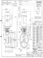
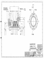
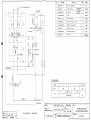
BOSUN'S STORE
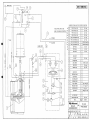
BOW THRUSTER
* MARKED PIPE AND VALVE TO BE SUPPLIED BY SHIPYARD
THESE PIPES ARE TO BE
DONE FLUSHING OPERATION
15
PIPE (FOR LUB. OIL)
SGP 40A
14
PIPE (FOR LUB. OIL)
SGP 20A
PIPE (FOR LUB. OIL)
SGP 25A
PIPE (FOR LUB. OIL)
SGP 25A
12
11
PIPE (FOR OPERATING OIL)
SGP 32A
10
PIPE (FOR OPERATING OIL)
SGP 32A
PIPE (FOR OPERATING OIL)
STPG370S SchSO 20A
PIPE (FOR OPERATING OIL)
STPG370S Sch80 20A
STOP VALVE
5K 32A
STOP VALVE
5K 25A
STOP VALVE
5K 20A
-1
HAND PUMP
-4
OIL PORT
-3
AIR BREATHER
-2
LEVEL SWITCH
NORMAL CLOSE
-1
TANK FILTER
150 mesh
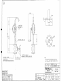
HEADER TANK
CAPA. 85L
SGP 40A
-11
-10
GAUGE COCK
-9
PRESSURE GAUGE
-a
CHECK VALVE
FLOW REGULATOR
-6
SOLENOID VALVE
-5
RELIEF SWITCH
SET 100kgf/cm2
-4
PRESSURE SWITCH
SET 4kgf/cm2
-3
ELECTRIC MOTOR
5.5KW x 4P
-2
GEAR PUMP
100kgf/cm2 x 22.9L
-1
HYD. PUMP UNIT
THRUSTER MAIN UNIT
NO.
TCT-220
W.
NAME
R.E.O.
KTE-MNAKASHIMA
MECHATRONICS DIVISION
•v
DRAWN
TRACED
REMARK
TCT-220
PIPING DIAGRAM
KTE CO..LTD.
APPROVED CHECKED
s.
SCALE
DATE OF OWN.
May 21, 2004
DRAWING NO.
KJ9000-001-0
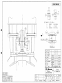
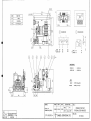
BOW THRUSTER
A
B
BOW THRUSTER CENTER
BOW THRUSTER CENTER
VIEW ON B
'
—*~ To "D" Port of Header Tank
"*~ To "C" Port of Header Tank
To "A" Port of Hyd. Unit
To Hand Pump
•
[
PORT
ST'BD A
To "B" Port of Hyd. Unit -»
04-10-22 Feedback box rearranged
04-09-02 Shipyard comments
DATE
MODIFICATIONS
ps K|M
ps K|M
APPROVED
510
PIPE ASS'Y
509
PIPE ASS'Y
508
PIPE ASS'Y
507
PIPE ASS'Y
NO.
NAME
STEEL PIPE
STPG370S
STEEL PIPE
STPG370S
STEEL PIPE
STPG370S
STEEL PIPE
STS370S
MATERIAL
1 set
1.4
1 set
1.8
1 set
2.6
2sets
1.2
WORK | SPARE
WEIGHT
R.E.Q.
KTE CO..LTD.
MECHATRONICS DIVISION
APPROVED CHECKED DRAWN
TRACED
NAME
TCT-220
PIPING ARRANGEMENT
SCALE
V DATE OF I
REMARK
DRAWING NO
1/8
3RD ANGLE PROJ
May 21, 2004
KJ9030-001-2
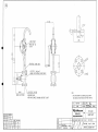
A135
027.7
085
HAND PUMP
m SB-20
koshin
STPG370S SchSO 20A
JIS F7301 5kg/cm2
MARINE CAST BRONZE GLOVE VALVE
JIS B2221 5K 20A
(WHEN FULLY OPENED)
NOTE.
WELDING FLANG
WITH PAIR FLANGE, PACKING, AND BOLT & NUT
1. THIS, HAND PUMP TO BE INSTALLED LESS THAN
MAX 3500mm HEIGHT ABOVE THE PROP. SHAFT £
506
NO.
HAND PUMP
STEEL PIPE
FC25 & STPG
NAME
MATERIAL
M
KTE-MNAKASHIMA
KTE CO..LTD.
MECHATRONICS DIVISION
PROCESSING TOLERANCE
DIVISION mm MID.
0.5more-Bunder
±0.1
6excess-30under
±0.2
30-
120
±0.3
120
315
±0.5
\L
MARK
APPROVED CHECKED
ROUGH GRADE
DRAWN
.«f
0.8 S
vw
6S
315
1000-
±0.8
w
12S
1000-
2000'
±1.2
V
35 S
04-12-15
NO.
DATE
Dimension review
Drawing no. changed
MODIFICATIONS
TRACED
APPROVED
i.
3.5kg
WORK SPARE
R. E. Q
REMARK
TCT-220
NAME
HAND PUMP
SCALE
DATE OF OWN.
1/4 (1/2)
May 21, 2004
AKJ5006-001-1
SKETCH
PORT
REMARKS
58
HYD. PUMP UNIT
A, B
JIS B2291
210kgf/cm 2 WELDED FLANGE
20A, SSA
SHIPYARD SUPPLY
76
HYD. PUMP UNIT
T
JIS B2291
210kgf/cm 2 WELDED FLANGE
32A, SSA
SHIPYARD SUPPLY
22
22
THRUSTER BODY
A', B'
JIS B2291
210kgf/cm 2 WELDED FLANGE
20A, SSA. SSB
STPG370S Seh 80 20A
SHIPYARD SUPPLY
THRUSTER BODY
& HEADER TANK
C, C'
JIS B2221
5kgf/cm2 WELDED FLANGE
25A
D, D'
SHIPYARD SUPPLY
HYD. PUMP UNIT
& HEADER TANK
S, S'
T
JIS B2221
5kgf/cm2 WELDED FLANGE
32A
SHIPYARD SUPPLY
THRUSTER BODY
& HAND PUMP
E, E'
JIS B2221
5kgf/cm2
20A
SHIPYARD SUPPLY
WELDED FLANGE
TCT-220
KTE - H NAKASHIMA
NAME
KTE CO..LTD.
A
APPROVED
05-08-22
NO
DATE
Misswriting
MODIFICATIONS
PORT CONNECTION
MECHATRONICS DIVISION
DAEWOO H-4437/38/41 BOW THRUSTER
pSK|M
i4*
APPROVED
^
DRAWN
TRACED
SCALE
OATE OF
Dec. 20, 2004
DRAWING NO.
KJ90 10-001-1
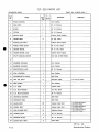
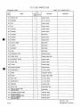
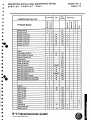
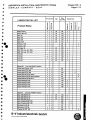
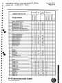
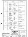
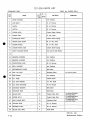
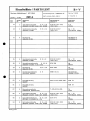
TCT-220 PARTS LIST
DWG. No. KJOOOO-003-1
STANDARD DWG.
Q' ty
Part
No.
NAME
Work
-ing
Spare
MATERIAL
1
GEAR HOUSING
1
Iron Casting
2
HUB BODY
1
Ni. AI. Bronze
3
BLADE
4
Ni. AI. Bronze
4
PISTON
1
Ni. AI. Bronze
5
CROSS HEAD
1
Carbon Steel Casting
6
CRANK RING
4
Cr. Mo. Steel
7
PROPELLER SHAFT
1
Carbon Steel Forging
8
PINION DRIVE SHAFT
1
Ni. Cr. Mo. Steel
9
CROWN WHEEL
1
Ni. Cr. Mo. Steel
10
CROWN WHEEL HUB
1
Carbon Steel Forging
11
SHAFT SEALING DEVICE
1
Iron Cast. & Nitril Rubber
13
BEARING HOUSING
1
Iron Casting
14
BEARING HOUSING
1
Iron Casting
15
PROTECTION PLATE
1
Ni. AI. Bronze
16
SEAL HOUSING
1
Iron Casting
17
INTERMEDIATE COVER
1
Mild Steel
18
HEX. HD. BOLT
4
Stainless Steel
19
END COVER
1
Iron Casting
20
O.T. TUBE
1
Carbon Steel
21
O.D. BOX (INSIDE)
1
Co. Mo. Steel
22
O.D. BOX (OUTSIDE)
1
Ni. AI. Bronze
23
DISTANCE WASHER
1
Mild Steel
24
DISTANCE RING
1
Mild Steel
25
BLADE BOLT
20
Copper Alloy Rod
26
DOWEL BOLT
4
Copper Alloy Rod
27
HUB FLANGE BOLT
12
Stainless Steel
28
SLIDING SHOE
4
Ni. AI. Bronze
29
BEARING PLATE
2
Ni. AI. Bronze
30
BLADE SEAL RING
4
NOK 06GF
REMARKS
12
Tm=71N-m(7.2kgrn)
Tm=835N-m(85.0k£rm)
with MoS2 Paste
Tm=835N-m(85.0kg-m)
with MoS2 Paste
Tm=1.1kN-m(111kffm)
with MoS2 Paste
KTE Co., Ltd.
P-1/6
Mechatronics Division
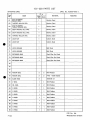
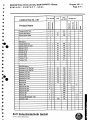
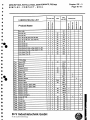
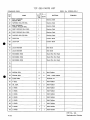
TCT-220 PARTS LIST
DWG. No. KJOOOO-003-1
STANDARD DWG.
1
Q ty
Part
No.
NAME
Work
-ing
MATERIAL
Spare
31
KNOCK PIN
8
Carbon Steel
32
BEARING
1
Ni. AI. Bronze
33
KEY
1
Carbon Steel
34
KEY
1
Carbon Steel
35
SPACER
1
Carbon Steel
36
SPACER
1
Carbon Steel
37
SPACER
1
Mild Steel
38
SPRING
8
Spring Steel
39
SPRING
6
Spring Steel
40
SHAFT LINER
1
Mild Steel
41
COVER
1
Mild Steel
42
BRACKET
1
Mild Steel
43
ARM
1
Mild Steel
44
FEEDBACK ROD
1
Stainless Steel
45
GUIDE ROD
1
Copper Alloy Rod
46
SPROCKET IDLER
1
Carbon Steel
47
IDLER PIN
1
Carbon Steel
48
U-NUT
1
Carbon Steel
49
ROLLER CHAIN
1
Carbon Steel
50
CHAIN BOLT
1
Cr. Mo. Steel
51
BUSH
1
Phosphor Bronze
52
PLATE
1
Copper Alloy Plate
53
HEX. NUT
1
Cr. Mo. Steel
54
CHAIN BOLT
1
Cr. Mo. Steel
55
SPACER
1
Carbon Steel
56
SPLIT PIN
1
Steel Wire Rod
57
HEX. SLOTTED AND
CASTLE NUT
1
Mild Steel
58
TAPERED ROLLER BRG.
1
Bearing Steel
SELF-ALIGNING
THRUST ROLLER BRG.
SELF-ALIGNING
ROLLER BRG.
1
Bearing Steel
1
Bearing Steel
59
60
REMARKS
KTE Co., Ltd.
P-2/6
Mechatronics Division
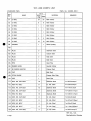
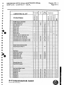
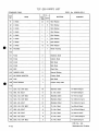
TCT-220 PARTS LIST
STANDARD
DWG.
DWG.
No. KJOOOO-003-1
1
Q ty
Part
No.
NAME
Work Spare
-ing
MATERIAL
61
SELF-ALIGNING
ROLLER BRG.
1
Bearing Steel
62
TAPERED ROLLER BRG.
1
Bearing Steel
63
SELF-ALIGNING
THRUST ROLLER BRG.
1
Bearing Steel
64
DEEP GROOVE BALL BRG.
1
Bearing Steel
65
DEEP GROOVE BALL BRG.
1
Bearing Steel
66
TAPERED ROLLER BRG.
2
Bearing Steel
67
LOCK NUT
1
Carbon Steel
68
LOCK NUT
1
Carbon Steel
70
LOCK WASHER
1
Mild Steel
71
LOCK WASHER
1
Mild Steel
72
RETAINING RING
1
Steel Wire Rod Hard
73
RETAINING RING
1
Steel Wire Rod Hard
74
RETAINING RING
1
Steel Wire Rod Hard
78
PISTON SEAL
2
2
Nitril Rubber
79
PISTON SEAL
2
2
PTFE + Nitril Rubber
80
SLIDE RING
2
81
V SEAL
1
1
Nitril Rubber
82
OIL SEAL
2
2
Nitril Rubber
83
0 RING
1
1
Nitril Rubber
84
O RING
1
1
Nitril Rubber
85
0 RING
1
1
Nitril Rubber
86
0 RING
1
1
Nitril Rubber
87
O RING
1
1
Nitril Rubber
88
0 RING
1
1
Nitril Rubber
89
O RING
1
1
Nitril Rubber
90
O RING
1
1
Nitril Rubber
REMARKS
69
75
76
77
TURCITE 47
.
KTE Co., Ltd.
P-3/6
Mechatronics Division
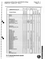
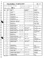
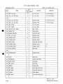
TCT-220 PARTS LIST
DWG. No. KJOOOO-003-1
STANDARD DWG.
Q' ty
Part
No.
NAME
Work Spare
-ing
MATERIAL
REMARKS
91
0 RING
24
24
Nitril Rubber
92
0 RING
8
8
Nitril Rubber
93
0 RING
1
1
Nitril Rubber
94
0 RING
1
1
Nitril Rubber
95
O RING
1
1
Nitril Rubber
96
O RING
1
1
Nitril Rubber
97
O RING
3
3
Nitril Rubber
98
0 RING
12
12
Nitril Rubber
99
PACKING
1
1
Sheet Packing
101
PLUG
3
Stainless Steel
102
PLUG
1
Carbon Steel
103
PLUG
2
Mild Steel
104
PLUG
1
Mild Steel
105
PIPE
1
Steel Pipe
106
RUBBER HOSE
2
Special Rubber
107
90 ELBOW ADAPTER
2
Carbon Steel
108
CLIP
1
Mild Steel
109
PITCH GAUGE
1
Copper Alloy Plate
110
PIPE
1
Steel Pipe
111
SOG. HD. CAP BOLT
16
Stainless Steel
Tm=481N-m(49kg-m)
112
HEX. HD. BOLT
8
Cr. Mo. Steel
Tm=520N-m(53kg-m)
113
SOG. HD. CAP BOLT
12
Stainless Steel
Tm=71N-m(7.2kcrm)
114
SOG. HD. CAP BOLT
8
Stainless Steel
Tm=138N-m(14.1kg-m)
115
HEX. HD. BOLT
12
Stainless Steel
Tm=138N-m{14.1l<erm)
116
SOG. HD. CAP BOLT
8
Cr. Mo. Steel
Tm=62N-m(6.3kerm)
117
HEX. HD. BOLT
6
Cr. Mo. Steel
Tm=107N-m(10.9kg-m)
118
HEX. HD. BOLT
2
Cr. Mo. Steel
Tm=22N-m(2.2kgrn)
119
HEX. HD. BOLT
8
Cr. Mo. Steel
Tm=1.78N-m(182kcrm)
120
SOG. HD. CAP BOLT
2
Cr. Mo. Steel
Tm=265N-m(27kg-m)
100
KTE Co., Ltd.
P-4/6
Mechatronics Division
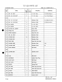
TCT-220 PARTS LIST
STANDARD
DWG.
DWG. No. KJOOOO-003-1
1
Q ty
Part
No.
NAME
Work
-ing
Spare
MATERIAL
REMARKS
121
HEX. HD. BOLT
4
Cr. Mo. Steel
Tm=520N-m(53kg-m)
122
SOC. HD. CAP BOLT
6
Cr. Mo. Steel
Tm=9.1N-m(0.93kg-m)
124
SOG. HD. CAP BOLT
4
Stainless Steel
Tm=138N-m(14.1kg-m)
125
SOC. HD. CAP BOLT
8
Stainless Steel
Tm=28N-m(2.9kg-m)
126
SET SCREW
4
Cr. Mo. Steel
127
SET SCREW
3
Cr. Mo. Steel
128
SLOTTED HD. SCREW
4
Brass Plate
129
SPRING PIN
4
Spring Steel
130
SPRING WASHER
6
Steel Wire Rod
131
HEX. HD. BOLT
1
Stainless Steel
132
LOCKING BAR
16
Stainless Steel
133
LOCKING BAR
1
Stainless Steel
134
POINT RING
1
Steel Wire Rod Hard
135
LOCKING WIRE
1
1
Stainless Steel
12m
136
LOCKING WIRE
1
1
Stainless Steel
5m
137
PLAIN WASHER
1
Mild Steel
139
LOCKING BAR
1
Stainless Steel
150
PLUG
1
Mild Steel
151
CARTRIDGE
1
Carbon Steel Pipe
152
LOCK PLATE
1
Mild Steel
153
SET PLATE
1
Mild Steel
154
SPRING
1
Spring Steel
155
SET RING
1
Steel Wire Rod Hard
156
SET RING
1
Steel Wire Rod Hard
157
O RING
2
158
SET RING
1
Steel Wire Rod Hard
159
ADAPTER
1
Carbon Steel
123
138
2
Nitril Rubber
KTE Co., Ltd.
P-5/6
Mechatronics Division
TCT-220 PARTS LIST
DWG. No. KJOOOO-003-1
STANDARD DWG.
1
Q ty
Part
No.
160
NAME
CUP
Work
-ing
1
Spare
MATERIAL
REMARKS
Mild Steel
KTE Co., Ltd.
P-6/6
Mechatronics Division
NOTE
1) 0 ring and their grooves to be greased up.
2) Bolts to be tightened with specified torgue.
>K1 Plug(101) of hub to be removed when oil is poured into the thruster,
after oil will be overflown, plug to be tightened with seal tape and
locked by punching.
%2 Plug(lG2) to be removed when oil is poured into the thruster,
after oil will be overflown, plug to be tightened with seal tape.
^3 To be mounted with grease.
*4 To be locked by welding.
%5 To be mounted with liquid packing. (Three Bond 1102)
*6 To be tightened with LOCTITE 242.
SS7 To be locked by punching.
To be locked by welding and apply the filler(PORTLAND CEMENT).
To be locked by welding and apply the filler(RESINOUS PUTTY)
in the grooves.
NAME
KTE-MNAKASHIMA
KTE CO..LTD.
MECHATRONICS DIVISION
PROCESSING TOLERANCE
DIVISION mm MIO.
DRAWN
\ 7
WORK SPARE
WQGHT
R.E.Q.
MATERIAL
TRACED
NAME
REMARK
TCT-220
G. A. OF THRUST UNIT
SCALE
1/7
3rd ANGLE PRO)
MARK
ww
vw
_w
V
DATE OF OWN
Oct. 23, 2003
DRAWING NO.
KJOOOO-003-1
INSTRUCTION MANUAL
FOR
PROPELLER SHAFT SEALING DEVICE
TYPE : SC 2 A
DESCRIPTION, INSTALLATION, MAINTENANCE, REPAIR
S I M P L E X - C O M P A C T
S E A L
195-0
§
1. GENERAL DESRIPTION OF AFT SIMPLEX-COMPACT SEAL
Type: SC 2 A
$
»'"•
The seal consists essentially of the stationary part, the
casing with three sealing rings, and the rotating part, the
liner.
The casing itself consists of individual rings which are '
bolted together (2,3,4 and 5), between which the three
sealing rings (31,6) are housed. The sealing ring (31)
serves mainly as a dirt deflector, while the sealing rings
(6) seals against sea water, oil resp..
Further details relating to individual parts and materials,
from which the seal is made are shown in the enclosed parts
list.
B+V Industrietechnik GmbH
P.O. Box 112289. 0-20422 Hamburg
DESCRIPTION, INSTALLATION, MAINTENANCE, REPAIR
S I M P L E X - C O M P A C T
S E A L
1.
INSTALLATION OF THE SEAL
1.1
GENERAL
195-1
Before the seal is installed, the bearing housing and the
propeller shaft must be checked to ensure absolute
. cleanness.
Taking into consideration the tolerances shown in the
seal installation drawing, the connecting dimensions in
way of the propeller hub, the bearing housing and- the •
propeller shaft must be checked.
It must also be checked whether the design length of the
seal can be kept to .
The seal shall only be taken from its plastic bag just
before commencing with the installation.
The wood blocks which are provided on the housing flange
for the protection of the liner can be removed later.
During the installation (and during a later removal) of
the seal the liner must under no circumstances be
withdrawn from the casing in order to avoid damage to the
surface and the sealing ring lip.
B+V Industrietechnik GmbH
P.O. Box 11 22 89, 0-20422 Hamburg
DESCRIPTION, INSTALLATION, MAINTENANCE, REPAIR
S I M P L E X - C O M P A C T
S E A L
^
3
3
$
:
2.
INSTALLATION OF THE SEAL
2.1
AFT SEAL
195-1
- Before the seal is pushed onto the propeller shaft the
latter must be checked for cleanness.
- The seal is then taken out of the plastic bag and
examined for damage sustained during the transport.
- The gasket (80) and the seal assembly with the fitted
liner (1) are placed on the shaft.
- The gasket (80) is then placed in position. Care must
be taken to ensure that bores in the casing flange are
kept clear.
- The wood blocks are now removed from the casing flange.
- The casing is secured by means of two bolts (7).
- The lifting bracket (20) is removed and stored onboard,
together with the respective fixing bolts (21).
- Threaded bores are now sealed, using plugs (22) and
packings (19) .
- The remaining bolts (7) are tightened cross-wise,
and secured using chrome steel wire.
- Screws (14) at liner flange (1) are unscrewed.
- Screws (14) are removed from cover ring (5) with
mounting straps (16).
- Removed srews (14) with mounting straps (16) are stored
on board.
- Screws (55) and replacing screws (14) are inserted into
cover ring (5) .
- The liner (1) is then cautiously pushed into the seal
casing.
- The gasket (81) is placed in position.
- The liner (1) is then moved to make contact with the
propeller and secured by bolts (10) and sealing washers
(17).
- Centring of the liner is checked by two dial gauges
simultaneously in chamber II and between the
cover ring and liner flange in accordance.
See enclosed table 7-195-1260
- The bolts (10) are secured using chrome steel wire
(18).
B+V Industrietechnik GmbH
P.O. Box 11 2289, D-20422 Hamburg
DESCRIPTION, INSTALLATION, MAINTENANCE, REPAIR
S I M P L E X - C O M P A C T
S E A L
3.
195-2
OIL FILLING OF AFT SEAL
- Socket pipe plugs (11,12) to be removed.
- The bearing housing to be filled with oil (see Note
below)
Ä
Note: - In case of low temperatures or if oil having an
increased viscosity has to be filled, we
recommend to heat the oil up to 60°C / 70°C;
however, the oil should not' exceed this"
temperature.
- Care shall be taken that the bearing housing is
completely vented during filling to ensure
complete filling of oil.
~
™
- The bearing housing thus completely filled with oil
should remain at the specified operating pressure for
~
*
j^
at least one hour.
9
\
^
^
- After the system has proven tight, the screw plugs
(11,12), for oil drain, shall be inserted oiltight.
- The oil chambers between the sealing rings of the aft
seal shal be filled with oil.
(For filling quantity see enclosed table)
^
- Socket pipe plugs (11,12), for oil filling and venting,,
to be inserted oiltight.
4.
LUBRICATION CONTROL
The maximum oil temperature should not exceed 60°C when
using sealing rings made of Perbunan and 110°C should not
be exceeded when sealing rings made of Viton are used.
Excess temperatures will have an adverse effect on the
lifetime of the sealing rings.
In case extreme temperatures are observed, the cause
shall be searched for.
B+V Industrietechnik GmbH
P.O. Box 112289, D-20422 Hamburg
Chapter 195 - 2
Sheet 4 / 5
DESCRIPTION, INSTALLATION, MAINTENANCE, REPAIR
SIMPLEX - COMPACT - SEAL
5.
FILLING QUANTITY OF THE AFT AND FORWARD S.C.-SEAL
(Without Oil Tank and Piping)
Filling Quantity in Litres
I
tt
rr-n
^
ß
Chamber
Size
Sem
HI
FORWARD SEAL
Chamber
[I
IH
0.10
0.12
500
I
125
[77771
samcasHI
II Size
I
same asHI
a
01
0.67
0.71
0.71
0.75
140
-
0.14
0.15
530
160
-
0.15
t).l~
560
-
0.31
0.87
180
-
0.16
0.13
600
-
0.86
0.93
200
•
0.17
0.19
630
-
0.90
0.98
220
-
0.19
021
670
-
0.9f>
1.04
240
-
023
025
710
•
124
1.19
\.-U
i*
s
- 260
t
025
027
750
t.ll
IJ1
=»280
it
027
029
800
125
1.63
300
-
028
0.31
850
1.40
1.73
330
•
OJl
OJU
900
1.64
2.06
355
-
0.40
0.44
950
1.74
2.17
380
«
0.43
0.47
1000
1.77
22S
400
-
0.45
0.49
1060
2.04
2.33
420
-
0.47
0.52
1120
2.00
3.05
197
0.60
0.64
1180
2.00
320
A,o
0.64
0.68
1250
1.92
3.50
/344
450
i*
480
•
•195-2-A.E
Dated: 19.01.98
B+V Industrietechnik GmbH
P.O. Box 11 2289, D-20422 Hamburg
VV //
/
-V
-A
2-i \
\
\
\
DESCRIPTION, INSTALLATION, MAINTENANCE, net- MIR
S I M P L E X - C O M P A C T - SEAL
Page 1 / 11
LUBRICATING OILS
The SIMPLEX-COMPACT seal is fitted with sealing rings of Perbunan (Nitrile)
or Won, depending on the operating conditions.
The following list shows the types of oil that are approved by BVI. The
technical data has been given to us by the oil companies.
*
•
The correct sealing ring material is given for every oil listed.
Oils marked with two astersks *" are, in particular, environmentally compatible
lubricants. They should be used only in consultation with us.
We ask you to inform us if oils / lubricants not on this list are to be used. We
shall test these lubricants accordingly.
*
j*
r
r
!•*
B+V Industrietechnik GmbH
PO. Box 11 22 89. 0-20422 Hamburg
cnaptenao
Page 21
DESCRIPTION, INSTALLATION, MAINTENANCE, REPAIR
SIMPLEX-COMPACT-SEAL
LUBRICATING OIL LIST
Product Name
"z
*h»
"c"
o
z_
3
Vise.
CSL40-C
0
a
K.
O
5C
X
X
General use:
"5
&
IL
Hydraulic Oil
SÄE
Gearbox Oil
For use with
0
X
X
5
Agip
Acer 100
Cladium 120
Cladium 120 SAE30
X
Cladium 300
Elf
40
160
X
X
30
108
X
X
40
160
X
Cladium 400 SAE30
X
30
108
X
X
40
160
X
X
30
108
X
Diesel Gamma
X
X
30
•108'
X
Diesel Sigma S
X
X
30
105
X
-
Ote68
X
64
X
. X
OteBO
X
80
X
X
Aral
Elf
Elf
Elf
Elf
Elf
Elf
Ef
X
Cladium 400 SAE40
Cladium 50 SAE30
*
100
(see also ELF Marine Products)
Atlanta Marine 30
X
X
Atlanta Marine D 3005
X
X
Aurelia 3030
X
X
Aurelia 4030
X
X
Turbine! 100
X
X
Turbine T 68
„
X
X
Discla ,V! 2CT7S
X
X
Otsola M 4015
X
X
Kowal M30
X
X
Kowal M40
X
X
30
30
30
40
30
20
30
40
30
40
105
X
105
X
110
X
140
X
95
X
71
X
110
X
145
X
•
105
X
X
145
X
X
X
318
X
BP
Bartran 320
X
460
X
Bartran HV 68
X
X
66
X
Energol DL-MP 30
X
X
30
110
X
Energol DL-MP 40
X
X
148
X
Energol OS 3-1 53
X
X
40
30
110
X
Energol DS 3-154
X
X
40
148
X
Energol GR-XP 100
X
X
96
X
Energol GR-XP 150
X"
X
152
X
X
320
X
X
96
Bartran 460
Energol GR-XF 320
Energol HLP 100
B+V Industrietechnik GmbH
P.O. Box 112289, D-20422 Hamburg
X
X
Chapter 195-3
Page 3 /11
DESCRIPTION, INSTALLATION, MAINTENANCE, REPAIR
S I M P L E X - C O.M P A C T - S E A L
SÄE
?
Product Name
Energol HLP 46
Energol HLP 58
IT
a
Z.
>,
E
m
•s.
z
SC
u.
X
X
46
X
X
X
69
X
Energol IC-HFX 303
Energol IC-HFX 304
Energol IC-HFX 403
Energol IC-HFX 404
Energol IC-HFX 504
Energol OE-HT 30
General use:
Engine Oil
LUBRICATING OIL LIST
Vise.
cSt40*C
Hydraulic Oil
or use with
Gearbox OH
r
X
30
110
X
X
40
148
X
X
30
110
X
X
40
x '
X
X
30
X
X
30
148
148
110
0
£
0
X
X
•
Caltex
Diesel Engine Oil R&O
Marine Engine Oil Special
Meropa Lubricant 150
Regal Marine
Regal Oil R&O 100
Regal Oil R&O 63
RPMDelolOOOil
RPMDelo100OilSAE30
RPMOelo 1000 Marine Oil
RPM Oelo 2000 Marine Oil
RPM Oelo 300 Oil
RPM Oelo 300 Oil SAE30
RPM Oeio 3000 Marine Oil SAE30
RPM Oelo 3000 Marine Oil SAE40
Castro!
21 5 MX Super
220 MX Super
Alpha SP 100
Alpha ZN 100
Alpha ZN 150
Alpha ZN 68
Coral 2
Coral 0
CRO-OB 30
HyspinAWHIOO
Marine COX 30
..
X
30
X
40
X
X
X
X
X
X
X
X
X
X
X
X
X
X
X
X
X
X
X
X
112
177
150
77.3
96.2
65.5
60.7
93,9
110
X
X
X
X
20/20W
30
30
30
20/20W
30
30
40
X
X
30
103
X
X
X
40
136
X
X
X
100
X
X
X
100
X
X
X
X
X
X
150
68
X
X
X
X
X
X
X
X
X
X
B+V Industrietechnik GmbH
P.O. Box 112289. D-20422 Hamburg
X
102
60.2
96.8
106
163
X
222
254
30
108
X
X
X
100
30
103
X
X
Chapter 195-3
Page 4/11
DESCRIPTION, INSTALLATION, MAINTENANCE, REPAIR
SIMPLEX - C O M P A C T - S E A L
Product Name
?
^
£
Z_
>.
e
ta
Vise.
cSL40*C
General use:
O
a
Ü»
•£.
u.
Ul
Marine Heavy
X
X
30
99
X
Marine MLC 30
X
X
30
107
X
MPX30
X
X
30
103
X
MXD 153
X
X
30
103
X
MXD 154
X
X
40
143
X
Nato 0-274
X
X
30
101
X
Perfecto T 100
X
X
PerfectoTSa
X
X
RX Super 30
X
X
MHP 153 {ren. TLX 153)
X
MHP 154 (ren. TLX 154)
96
63
0
X
30
108
X
X
30
102
X
X
40
136
X
30
102
X
X
X
TLX 204
X
X
40
138
X
TLX 304
X
X
40
137
X
X
40
135
X
Cepsa Sp
to
9
£
X
TLX 203
TLX 404
Hydraulic Oil
LUBRICATING OIL LIST
SAE
Gearbox oil
For use with
(see also Mobil Products)
Cepsa Mobil Delvac 1330
X
X
101
Cepsa Mobil DTE 16M
X
X
70
X
X
Cepsa Mobil DTE 1SM
X
X
103
Cepsa Mobil DTE Oil Heavy
X
X
80
X
X
Cepsa Mobil DTE Oil Heavy Medium
X
X
65
Cepsa Mobil DTE Oil NO. 3
X
X
110
Cepsa Mobilgard 312
X
X
110
X
Cepsa Mobilgard 324
X
X
111
X
Cepsa Mobilgard 412
X
X
145
X
Cepsa Mobilgard 424
X
X
159
X
Delo 1000 Marine Oil
X
X
30
112
X
Delo 2000 Marine Oil
X
X
30
106
X
Delo 3000 Marine Oil
X
X
30
104
X
Gear Compound EP 100
X
X
100
X
Gear Compound EP 150
X.
X
150
X
Chevron
(see also FAMM Products)
Mechanism IPS 46
X
46
Mechanism IPS 68
X
X
68
Turbine Oil GST 100
X
X
100
B+V Industrietechnik GmbH
P.O. Box 112289, D-20422 Hamburg
X
Chapter 195-3
Page 5/11
SAE
3T
z.
tr
o
Product Name
FKM(Vilon)
LUBRICATING OIL LIST
Vise.
cSt40*C
General use:
5
0
"&
111
30
68
114
X
X
30
108
X
X
X
X
Disola M 3015
X
X
Disola M 4015
X
X
Disola MT 30
X
X
Aurelia 3030
X
X
Aurelia 4030
X
X
40
105
105
110
145
110
110
140
X
:X
30
30
30
40
30
30
Turbine T 100
X
X
30
Turbine T 68
X
X
20
Essolube X 301 SAE 30
Essolube X 301 SAE4Q
X
X
30
X
X
40
Exxmar 12 TP 30
X
X
30
Exxmar 12 TP 40
X
X
40
Exxmar 24 TP 30
X
X
30
Exxmar 24 TP 40
X
X
.40
Exxmar XA
X
X
30
Exxmar XP
X
X
30
Nuto H 68
X
X
103
149
110
146
110
146
110
110
68
Spartan EP 100
X
X
100
X
Spartan EP 150
X
X
150
320
220
X
Turbine Oil GST 68
X
X
Veritas 300 Marine
X
X
Veritas Marine R&O
X
Hydraulic Oil
^r use with
Gearbox Oil
DESCRIPTION, INSTALLATION, MAINTENANCE, REPAIR
SIMPLEX- COMPACT-SEAL
0
s.
O
X
Elf Marine '
Atlanta Marine 30
Atlanta Marine D 3005
X
X
X
X
X
X
95
71
X
X
EXXON Marine
Spartan EP 320
X
Stermar 220
X
Teresso 32
X
X
Teresso Sa/TROMAR T 68
X
X
UNIVIS N 100
X
X
B+V Industrietechnik GmbH
P.O. Box 112289. 0-20422 Hamburg
100
32
68
93
X
X
X
X
X
X
X
X
X
X
X
X
X
X
Chapter 195- 3
Page 5111
DESCRIPTION, INSTALLATION, MAINTENANCE, REPAIR
SIMPLEX-COMPACT-SEAL
LUBRICATING OIL LIST
Product Name
Vise.
cSL40*C
General use:
5"
*
Q
2.
>_
5
o
c
u.
*
tu
cn
m
0>
Hydraulic Oil
SAE
Gearbox Oil
For use with
a
O
FAMM TEXACO CHEVRON
Veritas 800 Marine 30
X
X
30
114
X
Delo 1000 Marine 30
X
X
30
109
X
Regal R&O 63
X
X
Meropa 150
X
65
150
Meropa 220
X
220
X
Meropa 320
X
320
X
Meropa 460
X
460
X
68
RandoHDZ68
X
X
Regal EP 100 (ren. Regal R&O 100)
X
X
Taro 16 XD 30 (ren.Taro XD 30)
X
X
30
Taro 16 XD 40 (ren. Tara XD 40)
X
X
40
Ursa Marine 30 (ren. Ursa Super LA 30)
Ursa Marine 40 (ren. Ursa Super LA 40)
X
X
30
X
X
40
92
98
139
88
135
X
X
X
X
X
X
X
X
Fragol Industrieschmierstoffe
Fragol Hydraulic TR46 {**)
46
X
X
Fuji Kosan
Fukkol AD Turbine 58
X
X
63
Fukkol Hydro! X-100
X
X
100
Fukkol Marine 312
X
X
30
Fukkol Marine 320
X
X
Fukkol SAE ACE 307
X
X
30
30
106
105
•107
Gorgonela S 30
X
X
30
106
X
X
X
Gorgonela S 40
X
X
40
147
X
X
X
Rubella 30
X
X
30
107
X
X
X
Rubella 40
X
X
40
148
X
X
X
Sagartia 30
X
X
30
106
X
X
X
X
X
40
147
X
X
X
"
General Sekiyu K.K.
See EXXON Products
Ina Maziva Rljeka Croatia
Sagartia 40
B+V Industrietechnik GmbH
P.O. Box 1122 89. D-20422 Hamburg
Chapter 195 - 3
Page 7/11
DESCRIPTION, INSTALLATION, MAINTENANCE, REPAIR
SIMPLEX-COMPACT-SEAL
LUBRICATING OIL LIST
General use:
K
CD
Z
FKM (Vllod)
"2
Vise.
cSt40*C
X
X
X
X
F-L Select Motor Oil
X
X
30
103
X
F-L Select Motor Oil 20W20
X
X
Kenoil R&O AW 68
Super-0 III Series 3 Motor Oil
X
X
X
20/W20
20/W20
30
68.2
67.6
106.4
X
X
Mobil Delvac 1330
Mobil Delvac 1340
X
X
96
X
X
X
30
40
X
X
X
X
140
46
69
X
Mobil DTE 15 M
Mobil DTE 16M
Mobil DTE 18M
Mobil DTE 19M
Mobil DTE Oil Extra Heavy
Mobil DTE Oil Heavy^
Mobil DTE Oil Heavy Medium
Mobil DTE Oil Mr. 5
X
X
Product Name
Turbo 32
Turbo 46
z_
O
B
C
01
tu
Hydraulic Oll
SAE
Gearbox Oll
For use with
32
46
a»
0
X
X
Kendall noviol b.v.
X
X
X
Kyodo Oil Co.
See Japan Energy Corp. ( ELF)
Mobil Oil
*
*
*
Mobilgard 300
Mobilgard 312
Mobilgard 330 '
Mobilgard 340
Mobilgard 412
*
X
X
X
X
X
X
102
147
140
80.7
53.9
X
X
X
X
X
X
50
X
X
X
X
30
30
X
X
X
X
238
108
104
X
X
X
X
X
X
X
X
30
30
40
40
106
106
141
X
143
X
40
50
X
X
145
247
385
X
305
X
X
Mobilgard 430
Mobilgard 440
X
X
X
X
Mobilgard 570
Mobil Sterntube Lubricant
X
X
X
X
X
X
*
NESTE
Neste Veihteisto 320 EP
B+V Industrietechnik GmbH
P.O. Box 1122 89, D-20422 Hamburg
X
Chapter 195-3
Page 8 f 11
:
orus«with
SAE
Product Name
2_
e
<a
Nippon Mitsubishi Oil Co.
Diamond Marine T 104
Diamond Marine T 203 A
Diamond Marine T 303 A
Diamond Marine T 304 A
MDL PS 30 (ren. Super MDL PS 30)
MDL HDS 30 (ren. Super MDL HDS 30)
X
30
X
40
145
X
30
40
95.5
106
113
111
X
X
X
X
30
30
X
X
30
X
X
X
X
X
X
X
X
X
X
X
X
30
30
30
30
30
30
X
X
X
X
X
X
o
jj
"3
*
•o
>.
3:
hv
fe
9
5
96
X
X
General use:
engine Oil
S"
*
FKM (Vlton)
LUBRICATING OIL LIST
Vise.
CSL40-C
Qearbox Oil
DESCRIPTION, INSTALLATION, MAINTENANCE, REPAIR
SIMPLEX - C O M P A C T - S E A L
141
109
Petrabras Distribuidora
Lubrax MD-300 SAE 30
Lubrax MD-400 SAE 30
Marbrax CAD-308
Marbrax CAD-65-OF
Marbrax CCD-3 10
Marbrax CCO-320
Marbrax CCD-330
Marbrax TR-36
103
114
109
109
t14
111
Reginol
Gear Gl 1
Hykraft 150
Hykraft 68
Industryqear EP 100
4
*
Shell
Araina S 30
Argina S 40
Arqina T 30
ArqinaT 40
Araina X 40
Arginia XL 40
Fluid BD 46 (~)
Gadinia 30
Gadinia 40
Melina 30
Melina 40
B+V Industrietechnik GmbH
P.O. Box 112289. D-20422 Hamburg
X
30
142
137
20
64
99
X
X
X
X
X
X
X
X
X
X
X
30
40
30
40
40
40
107
137
108
X
142
146
X
139
X
X
X
X
X
X
30
46
105
X
X
40
141
X
X
X
30
105
X
X
X
40
145
X
X
X
X
Chapter 195-3
Page 9/11
DESCRIPTION, INSTALLATION, MAINTENANCE, REPAIR
SIMPLEX - C O M P A C T - S E A L
?
Product Name
z_
e
01
*
FKM (Vllon)
LUBRICATING OIL UST
Vise.
cSt40*C
General use:
5
o
_c
"5
tu
30
104
Melina S 30 (ren. Talpa 30)
X
X
Omala 68
X
X
58
X
Omala 150
X
X
150
X
Omala 220
X
X
Rimula 30
Sirius 15W4ff (ren. Rimula TX 15W40)
X
X
30
X
40
Sirius FB 30
Talpa 50
Tellus 100
Morlina 100 (ren. Tellus C100 )
Morlina 46 (ren. Tellus C46)
X
X
X
X
30
50
X
X
Tellus T 100
Tellus T 63
Turbo T 46
X
X
Turbo
Turbo
Vitrea
Vrtrea
T 68
T 78
220
68
X
220
118
101
104
211
100
100
Hydraulic Oll
SAE
Gearbox Oll
For use with
i»
S
5
X
X
X
X
X
X
X
X
X
X
X
X
46
100
68
49
X
X
63
X
X
X
76
X
X
X
X
220
63
X
X
220
X
X
X
X
X
X
X
Showa Shell Sekiyu K.K.
See Shell Products
Statoil
Statoil Stemway 220
Teboil
Teboi!WardL10T
X
X
30
110
X
Dora AR 30
Meropa Lubricants 150
Rando HO 68
Regal Marine 100
X
X
30
113
X
Texaco
9
(see also FAMM Products)
X
X
X
Regal R&O 100
X
X
Regal R&O 68
X
X
B+V Industrietechnik GmbH
P.O. Box 112289, D-20422 Hamburg
150
68
X
X
30
X
X
103
X
92
68
X
X
Chapter 195 - 3
Page 10/11
or use with
SAE
j?
^
Product Name
2.
K
o
z
General use:
I Engine oil
LUBRICATING OIL LIST
Vise.
cSt 40'C
o
i.
X
u.
157
X
30
99
X
X
40
145
X
X
30
98
X
X
X
40
139
X
Taro XL 40
X
X
40
145
X
Ursa Oil ED 30
X
X
30
97
X
Ursa Oil ED 40
X
X
40
173
X
Ursa Marine 30 (ren. Ursa Super LA 30)
Ursa Marine 40 (ren. Ursa Super LA 40)
X
X
30
33
X
X
X
40
135
X
Ursa Super Plus 30
X
X
30
102
X
Ursa Super Plus 40
X
X
40
160
X
30
114.6
X
Taro 4-80
X
X
Tara DP 30
X
X
Taro DP 40
X
Taro 16 XD 30 (renTaro XD 30)
X
Taro 16 XD 40 (ren. Taro XD 40)
Hydraulic Oll
:
Gearbox Oll
DESCRIPTION, INSTALLATION, MAINTENANCE, REPAIR
SIMPLEX-COMPACT-SEAL
w
<a
O
TOTALF1NA
Alcano 303
Bakola 46
X
X
X
X
Balola 68
Caprano S 312
X
X
X
X
30
105.3
X
Caprano S 412
X
X
40
152
X
Dilano 310
X
X
30
103
Giran L 100'
X
X
102
X
Rna
Giran L 63
X
X
66.7
X
Rna
Rna
HydranTSXSa
X
X
63
Rna
Rna
Rna
Fina
Fina
Solco B 300 P
Cirfaan 100 (ren. Solna 100)
Rna
Rna
Fina
Rna
Fina
Fina
Fina
Rna
Rna
46.3
X
63.2
X
X
X
200
230
X
X
30
89.4
X
X
102,4
X
Cirban 150 (ren. Solna 150)
X
X
156
X
Stellano S 320
X
X
30
109.4
X
Stellano S 420
X
X
40
156.6
X
Stellano S 430
X
X
40
163.6
X
Turbine Oil Heavy
X
X
Total
Carter EP 100
X
X
30
100
Total
CortisC
X
X
30
119
Total
Cortis MD
X
X
30
119
X
Total
Rubia H 30
X
X
30
100
X
Total
Rubia H 40
X
X
40
150
X
Total
Rubia S 30
X
X
30
100
X
Total
Rubia S 40
X
X
40
155
X
Neptan 220
B+V Industrietechnik GmbH
P.O. Bo* 112289, D-20422 Hamburg
X
80
X
X
X
Chapter 195- 3
Page 11/11
For use with
SÄE
?
w
Product Name
Z.
K
o
z
FKM(Vllon)
LUBRICATING OIL LIST
Vise.
cSt 40-C
Gene ral use:
5
o
"5»
tu
Gearbox Oil
DESCRIPTION, INSTALLATION, MAINTENANCE, REPAIR
SIMPLEX-COMPACT-SEAL
o
<j
3
q
•S
>.
r
h»
O
s
5
Vickers Leeds
Hydrox21(2024)
X
50
270
x
Hydrax550(2018)
X
X
20/30
70
X
Hydrox8EP(2019)
X
X
30
100
X
Dimol HD
X
X
30
105
Hydroma 52
X
X
30
100
Panta SAE20
Panta SAE30
Panta SAE40
X
X
20
60
X
X
X
X
30
40
100
145
Wisura
«
I*
l!
U
la
B+V Industrietechnik GmbH
P.O. Box 112289, D-20422 Hamburg
DESCRIPTION, INSTALLATION, MAINTENANCE, REPAIR
S I M P L E X - C O M P A C T
S E A L
195-4
*
I
1.
REPAIR OF THE SEAL
1.1
DESIGNATION OF SEALING RINGS
j
^
On principle all sealing rings are designated by the
numbers 1 through 3, counting from aft to forward
^
SEAL Nos.:
1 Dirt sealing ring
'9
2 Water sealing ring
'
3 Oil sealing ring
I
2.
EXCHANGE OF SEALING RINGS IN THE WORKSHOP
IA
2.1
PREPARING THE SEAL FOR TRANSPORT TO THE WORKSHOP
^
*
—
'
Ä
*A
- Discharge of bearing house oil
- Transport clamp (20) - in special substituted by an
eye bolt (55) - wood logs and mounting straps (16),
together with pertaining screws, to be taken ashore.
- Removal of hexagon screws (22) and hexagon screw
locking (19) .
- The transport clamp (20) is to be mounted using the
socket head cap screws (21). In special cases an
eye bolt (55) may be used.
- Disassembly of seal dependent on the design of the
propeller shaft in accordance with Sheet 195-1:
however, to be carried out in reverse order.
B+V Industrietechnik GmbH
P.O. Box 112289, 0-20422 Hamburg
DESCRIPTION, INSTALLATION, MAINTENANCE, REPAIR
S I M P L E X - C O M P A C T
S E A L
2.2
195-4
EXCHANGE OF SEALING RINGS OF THE SEAL IN THE WORKSHOP
-
Hexagon screws (14) at casing to be removed.
Liner (1) to be carefully pulled out of the casing.
Unbolt mounting straps (16)
The liner (1) to be cleaned, and running surface to be
skimmed if required.
See also enclosed skimming of liners.
- Separating of casing rings.
Note : - Wedge-shaped tools must not be used for
separating of casing rings.
*
*
a
'^
ia
l""
j^
"
~
~
A
A
*
L
*
•
- All casing rings shall be cleaned and internally
coated.
- New sealing rings shall, be inserted and subsequently
the individual casing rings shall be firmly re-bolted
with each other.
(In case of different material of the sealing rings,
care shall be taken that the correct order is ensured)
- The casing shall be externally coated.
- The liner (1) shall be oiled and carefully fitted in
the casing.
- Mounting straps (16) to be fitted and secured with
hexagon screws (14).
- The seal shall be well protected against dirt.
B+V Industrietechnik GmbH
P.O. Box 112289. D-20422 Hamburg
DESCRIPTION, INSTALLATION, MAINTENANCE, REPAIR
SIMPLEX - C O M P A C T - SEAL
4.
Chapter 195-5
Sheet 5 / 6
SKIMMING OF AFT AND FORWARD LINERS
For all sizes of S.C.-seal it is permissible for repair purposes to machine and grind
the liner to the measurement" D - x".
An exception to this are those S.C.-seal types which have the letter "C" in their
designation since those liners are ceramic-coated (e.g. SC 2 BC).
For every 1 mm reduced diameter of the liner the springs shall be shortened by 3
mm.
i:
O
-Stem
«I»
*
4
330
355
380
2,9
3,0
3.0
3.1
630
670
710
750
300
3.8
3.9
4.0
4.1
4.2
125
140
160
130
200
220
240
260
X max.
(mm)
2.5
2,5
2,5
2.6
2.6
2.7
2.7
2.8
2.8
Size D
(mm)
400
420
450
430
500
530
560
600
Xmax.
(mm)
3.1
12
3.3
3.4
3.4
3.5
3.6
3,7
Size D
(mm)
350
900
950
1000 1060
1120 1180 1250 1320 1400
Xmax.
4.4
4,5
4.5
4.8
5.0
4.9
5.2
•195-5.E
Oated:09.0ZJ3
«*
a
rf=
280 300
Size D
(mm)
B+V Industrietechnik GmbH
P.O. Box 112289. D-20422 Hamburg
5.4
5.5
5.8
1500 1600
6.1
6.3
B+ V
Einzelteilliste / PARTS LIST
Zeichnungs-Nr . /DRAWING-N 0
Hintere Abdichtung / AFT SEAL "
Größe / SIZE:
Anzahl
HO
Pos.
POS
>>Qft i AOV A
SAC: 3-557-0173-000. 4
Seite/ PAGE
1 won /of 2
BenonnuncT
Zaichnungs-Nzr .
DRMJTNG-N1*
works toff
Material
taaas
1
1
Laufbuchse
LINER
SAC: 3-557-0173-001.
Chromstahl
CHROME STEEL
2
1
Flanschring
FLANGE RING
SAC: 3-557-0001-002.
GG - 25
CAST IRON
3
1
Zwischenring
INTERMEDIATE RING
SAC: 3-557-0001-003.
GG - 25
CAST IRON
4
1
Zwischenring
INTERMEDIATE RING
SAC: 3-557-0001-004 .
GG - 25
CAST IRON
5
1
Deckelring, zweiteilig
COVER RING, TWO PART
SAC: 3-557-0001-005.
GG - 25
CAST IRON
6
1
Dichtring
SEALING RING
Viton blank
VITON PLAIN
7
12
Sechskantschraube
HEXAGON SCREW
M16 x 45
SAZ: 3-195-2598-000.
A4
STAINLESS STEEL
8
8
Sechskantschraube
HEXAGON SCREW
M 8 x 25
DIN EN 24017
(DIN 933)
A4 - 70
STAINLESS STEEL
.9
8
Zylinderschraube
M 8 x 40
HEXAGON SOCKET HEAD CAP SCREW
DIN EN ISO 4762
(DIN 912)
A4 - 70
STAINLESS STEEL
10
8
Sechskantschraube
HEXAGON SCREW
M12 x 35
11
3
Dichtring
SEALING RING
A17 x 21
12
3
13
KTE-NAKASHIMA
SUPPLY
DIN 7603
Cu
COPPER
Verschlussschraube
G 3/8 A
HEXAGON SOCKET PIPE PLUG
DIN 908
MS
BRASS
24
Sicherungsscheibe
SECURING WASHER
S8
HDWN 33131
Chromstahl
STAINLESS STEEL
14
8
Sechskantschraube
HEXAGON SCREW
M 8 x 12
DIN EN 24017
(DIN 933)
A4 - 70
STAINLESS STEEL
16
4
Montagebügel
MOUNTING STRAP
7-195-0021
St 37 - 2
STEEL
17
12
Dichtring
SEALING WASHER
SUSW 12
KTE-NAKASHIMA
SUPPLY
DIN EN 10218-2
Chromstahl
STAINLESS STEEL
W557
18
1
Sicherungsdraht
SAFETY WIRE
19
2
Sechskantschraubensicherg . M 8 HDWN 33155
HEXAGON SCREW LOCKING
Polyamid
POLYAMID
20
1
Transportbügel
TRANSPORT CLAMP
St
STEEL
0173
0 2 x 3600
7-195-0242
Einzelteilliste / PARTS LIST
Hintere Abdichtung / AFT SEAL
Größe / SIZE:
P03.
POS
Anzahl
NO
1Qf\ A
^OU /V
B-i- V
Zeichnungs-Nr. /DRAWING-N0
Seite/ PAGE
SAC:3-557-0173-000.4
2 von/of 2
Benennung
NAME
Zaichnungs-Hr .
DRAWING-N0
Werkstoff
Material
21
2
Zylinderschraube
M 8 x 35
HEXAGON SOCKET HEAD CAP SCREW
DIN EN ISO 4762
(DIN 912)
8.8
STEEL
22
2
Sechskantschraube
HEXAGON SCREW
DIN EN 24017
(DIN 933)
A4 - 70
STAINLESS STEEL
31
2
Dichtring
SEALING RING
55
4
Sechskantschraube
HEXAGON SCREW
58
3
59
M 8 x 14
Perbunan-S
PERBUNAN-S '
DIN EN 24017
(DIN 933)
A4 - 70
STAINLESS STEEL
Verschlussschraube
G 1/4 A
HEXAGON SOCKET PIPE PLUG
DIN 908
Ms
BRASS
3
Dichtring
SEALING RING
A14 x 18
DIN 7603
Cu
COPPER
60
4
Sicherungsscheibe
SECURING WASHER
S8
HDWN 33131
Chromstahl
CHROME STEEL
80
1
Flachdichtung
GASKET
SAZ: 3-195-2666-000.
AFM 34
81
1
Flachdichtung
GASKET
87
4
Korrosionsschutz
CORROSION PROTECTION
7-195-0335-000.
Zn
ZINC
88
4
Zylinderschraube
M 8 x 14
HEXAGON SOCKET HEAD CAP SCREW
DIN EN ISO 4762
(DIN
912)
A4 - 70
STAINLESS STEEL
90
2
Zylinderkerbstift
0 6 x 20
NOTCHED CYLINDRICAL PIN
DIN 1473
St
STEEL
93
8
Zylinderschraube
M 8 x 35
HEXAGON SOCKET HEAD CAP SCREW
DIN EN ISO 4762
(DIN 912)
A4 - 70
STAINLESS STEEL
W557 0173
M 8 x 8
AFM 34
12
10
Ansicht
VIEW
177^2
19,20,21,22
Dichtringe Pas. 17 und Schrauben
Pos X) von NAKASHIMA geü'efert
SEALING WASHER POS. 17 Ahfl SCREWS
POS. 10 DELIVERED BY NAKASHIMA
10+17
Anzugsmoment f. POS. 7=
TIGHTENNIG TORQUE F. POS. 7:
81
87,88+ 8.1393,13 58,59
90 9.13 90 2
Mm
>M
-19 Ölfüllung
1
'• 'L OIL
nu FILLING
Fil l IN
Enftuftung
VENTING
INI
"
(11.4 kgm)
80 7,18
Bb
PS
Stb
STB
14.16 "55.60 5 31
4
31 3 1 6
OL DRAIN
Schrauben trit LOTE 242/243 gesichert
SCREWS SECURED WITH LOCTlTE 242/243
Nur zum Transport
FOR TRANSPORT ONLY
Pos.5560 nach Demontage vqn Pos. 16 eingesetzt
POS.55^0 INSERTED ÅRER OfSMANTUNG OF POS.16
in 220
385.000
(8
-0.062
385.000
H9
^).KO
290.000
f8
-0.056
290.000
H8
»0.081
Poflmaf)
-0.151
0
-0.137
0
ah. Abndl unt Abmcd
Maflstab %
SMPLEX-COMPAa SEAL TYPE: SC2A
Datn
Our records ond data are subject to fult
protection under the law. Unauthorized
reproduction, complete or in extract fron,
as well as passing on of same or dbdasino,
its contents to third parties is strictly
prontited. Far granted patents we reserve aU
rights under para 7 at the German potent law.
ThyssenKrupp B«V IndustrfetechnBc GmbH
10
NOK
Kntere Abdichtung. Gr. 280
AFT SEAL. SIZE 280
OJUCH
15.V1.4S
Nra
H012005 lever
POS. B irt T7 ogndtrl «LKJOOJ
Pos. 17 at Tert
MiOl SinÄ9L»
Coful
MS22
B.V
Industrietechnik
GmbH
SAC=3-557-0173-000.4
Erik
End:
BUt
BOW THRUSTER
A
GG
SF COUPLING : PTC-1130-H
A
(OFFSET)
: MAX. 0.28mm
B
(GAP)
: 1.5-12.5mm
C-0 (ANGULAR) : MAX. 0.30mm
TO BE GREASE UP
VIEW
ON
A
609
.ÜBE PLUG
608
HEX. NUT
607
CAP SCREW
606
;EAL RING
NEOPRENE
N. B. R.
PTC-1130-H
605
GASKET
FIBER FLEX
PTC-1130-H
604
COVER
AI. ALLOY CAST
ALDCS-7
PTC-1130-H
603
GRID MEMBER
HSWR72B
PTC-1130-H
602
HUB
601
HUB
NO
CARBON STEEL
S45C
CARBON STEEL
S45C
NAME
MATERIAL
PTC-1130-H
PTC-1130-H
WORK
KTE-HNAKASHIMA
NAME
KTE CO..LTD.
PROCESSING
DIVISION mm
MID.
±0.1
6excess-30under
±0.2
30 •
120
±0.3
120
315 -
±0.5
315
1000'
±0.8
1000-
2000 •
±1.2
\
R.E.Q.
WBGHT
REMARK
TCT-220
SF COUPLING ASS'Y
MECHATRONICS DIVISION
TOLERANCE
0.5more-6under
SPARE
APPROVED CHECKED
/
MARK
DRAWN
0.8 S
vw
w
TRACED
SCALE
1/6
3rd ANGLE PROJ,
ROUGH GRADE
6S
12 S
35 S
DAEWOO H-4437/38/41
NO
DATE
MODIFICATIONS
APPROVED
±
DATE OF OWN.
May 21, 2004
DRAWING NO.
KJ6000-001-0
BOW THRUSTER
DETAIL C
SHAFT cfc
ROLLER CHAIN
DETAIL A
DETAIL B
SPRING WASHER
HEX. HD. BOLT
FOR DETAIL REFER TO THE DRAWING OF REMOTE CONTROL SYSTEM
SPRING WASHER
HEX. HD. BOLT
ROLLER CHAIN
FEEDBACK BOX
gh/
K-'I'm
j i j
i
KTE-NNAKASHIMA
TCT-220
KTECO..LTD.
MECHATRONICS DIVISION
FEEDBACK UNIT ASS'Y
rJ-Lj, I ! I
SPOT WELDING
Mar 21, 2004
Shipyard comment
pSK|U
KJ7000-001 -2
CO
TYPE
SHIPYARD
SHIP NO.
HEADER TANK
TCT-200
jOIUNG_PORT_(S_GP_4pA)
__
TO FILLING POINT No. 5 DECK
STERN THRUSTER
DAEWOO SHIPBUILDING & MARINE ENGINEERING CO., LTD.
BLADE TIP CLEARANCE
H-4437/38/41
if-
15mm
5mm
DESIGN
////////
MINIMUM
HYD. PUMP UNIT
i
[Approx. 2280|
i
/_i
1-
E7
L. W. L.
Q_
O
7
OP_ERAnNG_OILjSrPG_370S SchSO 20A) |
OPERATING OIL (STPG 370S SchSO 20A)
MOTOR 1050 kW
AC 30 440V 60Hz
SHIPYARD SUPPLY
NOMINAL THRUST : ABT. 16.4 TON
700 FEEDBACK UNIT ASSY
1 set
600 SF COUPLING ASS'Y
1 set
518 ANODE
517 SPRING WASHER
516 HEX. HO. BOLT
515 HEX. HD. BOLT
514 LOCKING WIRE
513 HEX. HD. BOLT
512 HEX. NUT
511 HEX. HD. BOLT
510 PIPE ASS'Y
509 PIPE ASSY
508 PIPE ASSY
A S
ST'BD<
—
507 PIPE ASSY
Q
506 HAND PUMP
l 505 STAY
i 504 MOTOR STAND
ALUMINUM
50 x 150 x 300
STEEL WIRE
SWRH6A
Cr. Mo. STEEL
SCM435
Cr. Mo. STEEL
SCM435
STAINLESS STEEL
SUS304
Cr. Mo. STEEL
SCM435
STAINLESS STEEL
SUS316
STAINLESS STEa
SUS316
STEEL PIPE
STPG370S
STEEL PIPE
STPG370S
STEEL PIPE
STPG370S
STEEL PIPE
STS370S
STEEL PIPE
FC25 & STPG
MILD STEEL
SS400
MILD STEEL
SS400
12
14
1. REFER TO NEXT PAGE (DWG NO. KI5100-001-1) FOR PLAN VIEW
2. X MARKED VALVES : SHIPYARD SUPPLY
0408-16
NO
DATE
Shipyard comment
MODIFICATIONS
M24 x 85
0.26
M20 x 85 03
20
0.026
20
M36 x 95 03
M20
0.29 M20 x 85
1 set
2.2
20A SchBO
1 set
2.6
25A SchSO
1 set
3.5
25A SchSO
2sets
2.4
20A SchSO
3.5
45
760
1050kW 6P
3360
kg
3460
NAME
WORK SPARE
WEIGH!
R.E.Q.
MATERIAL
APPROVED CHECKED DRAWN
04-12-20 Thruster reorranged
0.37
5500
KTE-HNAKASHIMA
KTE CO..LTD.
MECHATRONICS DIVISION
A
N0.2 24S
1.06
501 THRUSTER
NOTE:
WITH M16NUT.
WASHER(SUS3I6)
0.26
16
ROLLED STEEL
GRADE A
502 DUCT
FULL WELDING
5.5
10m 91.5
503 MOTOR
NO
PTC-1120-H
TRACED
REMARK
TCT-200
NAME
THRUSTER ARRANGEMENT
SCALE
1/20
3rdANO£PROJ
P.S.KIM
P.S.KIM
V
TOVE
DATE OF OWN.
May 21. 2004
DRAWING NO.
KI5000-001-2
STERN THRUSTER
[APPROX. 22801
PORT
PLAN VIEW
701
FEEDBACK BOX
504
MOTOR STAND
503
MOTOR
760
"550C
3360
ROLLED STEEL
SS400
502
DUCT
501
THRUSTER
NO.
MILD STEEL
SS400
WORK SPARE
MATERIAL
NAME
R. .Q.
DAEWOO H-4437/38/41
04-12-20 Shipyard comment
NO. DATE
MODIFICATIONS
APPROVED CHECKED
DRAWN
TRACED
REMARK
TCT-200
KTE-ÜNAKASHIMA
KTE CO..LTD.
MECHATRONICS DIVISION
WEIGHT
1050kW
NAME
PLAN VIEW
OF TRUSTER ARRANGEMENT
SCALE
1/25
3RD ANGLE PROJ
DATE OF
May. 21, 2004
DRAWING NO
KI5100-001-1
P.S. KIM
APP1WD
11
STERN THRUSTER
* MARKED PIPE AND VALVE TO BE SUPPLIED BY SHIPYARD
THESE PIPES ARE TO BE
DONE FLUSHING OPERATION
PIPE (FOR LUB. OIL)
PIPE (FOR LUB. OIL)
PIPE (FOR LUB. OIL)
PIPE (FOR LUB. OIL)
PIPE (FOR OPERATING OIL)
PIPE (FOR OPERATING OIL)
PIPE (FOR OPERATING OIL)
STPG370S Sch80 20A
PIPE (FOR OPERATING OIL)
STPG370S Sch80 20A
AIR BREATHER
LEVEL SWITCH
NORMAL CLOSE
PRESSURE GAUGE
CHECK VALVE
FLOW REGULATOR
SOLENOID VALVE
RELIEF SWITCH
SET 100kgf/cm2
PRESSURE SWITCH
SET 4kgf/cm2
ELECTRIC MOTOR
100kgf/cm2 x 22.9L
HYD. PUMP UNIT
THRUSTER MAIN UNIT
KTE-HNAKASHIMA
KTE CO..LTD.
MECHATRONICS DIVISION
PIPING DIAGRAM
May 21, 2004
KI9000-001-1
STERN THRUSTER
B
BOW THRUSTER CENTER
BOW THRUSTER CENTER
VIEW ON B
<— To "D" Port of Header Tank
«- To "C" Port of Header Tank
508)
To "A" Port of Hyd. Unit
To "E" Port of Hand Pump
l
To B Port of Hyd. Unit
—
SECTION
04-12-20 Shipyard comment
NO
DATE
MODIFICATIONS
P.S.KIM
APPROVE
ST'BD.
510
PIPE ASS'Y
509
PIPE ASS'Y
508
PIPE ASS'Y
507
PIPE ASS'Y
NO
NAME
A-A
STEEL PIPE
STS370S
STEEL PIPE
STS370S
KTE - H NAKASHIMA
1 set
2.4
1 set
3.1
STEEL PIPE
STS370S
1 set
4.3
STEEL PIPE
STS370S
2sets
2.6
MATERIAL
WORK SPARE
R.F.Q.
WEIGHT
KTE CO..LTD.
MECHATRONICS DIVISION
TRACED
APPROVED CHECKED
if
REMARK
,v xx
v
NAME
TCT-200
PIPING ARRANGEMENT
SCALE
1/8
3rd ANGLE PROJ.
DATE OF OWN.
May 21, 2004
DRAWING NO.
KI9030-001-1
A135
o
027.7
085
HAND PUMP
(«Oil SB-20
koshin
STPG370S SchSO 20A
JISF7301 5kg/cm 2
MARINE CAST BRONZE GLOVE VALVE
JIS B2221 5K 20A
NOTE.
WELDING FLANG
WITH PAIR FLANGE, PACKING, AND BOLT & NUT
(WHEN FULLY OPENED)
1. THIS HAND PUMP TO BE INSTALLED LESS THAN
MAX 3500mm HEIGHT ABOVE THE PROP. SHAFTS
STEEL PIPE
506
HAND PUMP
FC25 & STPG
NO.
NAME
MATERIAL
M
3.5kg
WORK SPARE
WEIGHT
R. E. Q
KTE-fcJNAKASHlMA
PROCESSING TOLERANCE
DIVISION mm MID.
V
0.5more-6under
±0.1
6excess-30under
±0.2
30-
120
±0.3
120 •
315 -
±0.5
315
1000-
±0.8
1000-
2000-
±1.2
KTE CO..LTD.
I
MARK
A vw
/ \ w
/ \ V
APPROVED CHECKED
ROUGH GRADE
DRAWN
TRACED
SCALE
0.8 S
6S
04-12-15
12 S
35 S
DATE OF DM
Dimension review
Shipyard comment
il ±
v?
NO.
DATE
MODIFICATIONS
APPROVE!
TCT-200
HAND PUMP
MECHATRONICS DIVISION
V7
\L
NAME
REMARK
1/4 (1/2)
May 21, 2004
KI5006-001-1
SKETCH
PORT
REMARKS
HYD. PUMP UNIT
A, B
JIS B2291
210kgf/cm 2 WELDED FLANGE
20A, SSA
SHIPYARD SUPPLY
76
HYD. PUMP UNIT
T
JIS B2291
210kgf/cm 2 WELDED FLANGE
32A, SSA
SHIPYARD SUPPLY
THRUSTER BODY
A', B'
JIS B2291
210kgf/cm 2 WELDED FLANGE
STPG370S Sch 80 20A
SHIPYARD SUPPLY
20A, SSA, SSB
10
THRUSTER BODY
& HEADER TANK
C, C'
JIS B2221
5kgf/cm 2 WELDED FLANGE
25A
D, D'
SHIPYARD SUPPLY
HYD. PUMP UNIT
& HEADER TANK
S, S'
JIS B2221
5kgf/cm 2 WELDED FLANGE
32A
T
SHIPYARD SUPPLY
10
THRUSTER BODY
& HAND PUMP
. . . 10
E, E'
JIS B2221
5kgf/cm2 WELDED FLANGE
20A
SHIPYARD SUPPLY
KTJE-ÜNAKASHIMA
KTE CO..LTD.
CHECKED
NO
DATE
^writing
MODIFICATIONS
PORT CONNECTION
MECHATRONICS DIVISION
DAEWOO H-4437/38/41 STERN THRUSTER
O5'03'22
TCT-200
NAME
DRAWN
P
pSK|M
TRACED
SCALE
WE OF
Dec. 20, 2004
DRAWING NO.
«190 10-001-1
rf
APPROVED
,i
„
t
TCT-200 PARTS LIST
DWG. No. KIOOOO-003-1
STANDARD DWG.
1
Q ty
Part
No.
NAME
Work Spare
-ing
MATERIAL
1
GEAR HOUSING
1
Iron Casting
2
HUB BODY
1
Ni. AI. Bronze
3
BLADE
4
Ni. AI. Bronze
4
PISTON
1
Ni. AI. Bronze
5
CROSS HEAD
1
Carbon Steel Casting
6
CRANK RING
4
Cr. Mo. Steel
7
PROPELLER SHAFT
1
Carbon Steel Forging
8
PINION DRIVE SHAFT
1
Ni. Cr. Mo. Steel
9
CROWN WHEEL
1
Ni. Cr. Mo. Steel
10
CROWN WHEEL HUB
1
Carbon Steel Forging
11
SHAFT SEALING DEVICE
1
Iron Cast. & Nitril Rubber
13
BEARING HOUSING
1
Iron Casting
14
BEARING HOUSING
1
Iron Casting
15
PROTECTION PLATE
1
Ni. AI. Bronze
16
SEAL HOUSING
1
Iron Casting
17
INTERMEDIATE COVER
1
Mild Steel
18
HEX. HD. BOLT
4
Stainless Steel
19
END COVER
1
Iron Casting
20
O.T. TUBE
1
Carbon Steel
21
O.D. BOX (INSIDE)
1
Co. Mo. Steel
22
O.D. BOX (OUTSIDE)
1
Ni. AI. Bronze
23
DISTANCE WASHER
1
Mild Steel
24
DISTANCE RING
1
Mild Steel
25
BLADE BOLT
20
Copper Alloy Rod
26
DOWEL BOLT
4
Copper Alloy Rod
27
HUB FLANGE BOLT
12
Stainless Steel
28
SLIDING SHOE
4
Ni. AI. Bronze
29
BEARING PLATE
2
Ni. AI. Bronze
30
BLADE SEAL RING
4
NOK 06GF
REMARKS
12
Tm=71N-m(7.2k£rm)
Tm=667N-m(68.0kcrm)
with MoS2 Paste
Tm=667N-m(68.0kcrm)
with MoS2 Paste
Tm=834N-m(85.1kgin)
with MoS2 Paste
KTE Co., Ltd.
P-1/5
Mechatronics Division
TCT-200 PARTS LIST
DWG. No. KIOOOO-003-1
STANDARD DWG.
1
Q ty
Part
No.
NAME
Work Spare
-ing
MATERIAL
31
KNOCK PIN
8
Carbon Steel
32
BEARING
1
Ni. AI. Bronze
33
KEY
1
Carbon Steel
34
KEY
1
Carbon Steel
35
SPACER
1
Carbon Steel
36
SPACER
1
Carbon Steel
37
SPACER
1
Mild Steel
38
SPRING
6
Spring Steel
39
SPRING
6
Spring Steel
40
SHAFT LINER
1
Mild Steel
41
COVER
1
Mild Steel
42
BRACKET
1
Mild Steel
43
ARM
1
Mild Steel
44
FEEDBACK ROD
1
Stainless Steel
45
GUIDE ROD
1
Copper Alloy Rod
46
SPROCKET IDLER
1
Carbon Steel
47
IDLER PIN
1
Carbon Steel
48
U-NUT
1
Carbon Steel
49
ROLLER CHAIN
1
Carbon Steel
50
CHAIN BOLT
1
Cr. Mo. Steel
51
BUSH
1
Phosphor Bronze
52
PLATE
1
Copper Alloy Plate
53
HEX. NUT
1
Cr. Mo. Steel
54
CHAIN BOLT
1
Cr. Mo. Steel
55
SPACER
1
Carbon Steel
56
SPLIT PIN
1
Steel Wire Rod
57
HEX. SLOTTED AND
CASTLE NUT
1
Mild Steel
58
TAPERED ROLLER BRG.
1
Bearing Steel
SELF-ALIGNING
THRUST ROLLER BRG.
SELF-ALIGNING
ROLLER BRG.
1
Bearing Steel
1
Bearing Steel
59
60
REMARKS
KTE Co., Ltd.
P-2/5
Mechatronics Division
TCT-200 PARTS LIST
DWG. No. KIOOOO-003-1
STANDARD DWG.
1
Q ty
Part
No.
NAME
Work
-ing
Spare
MATERIAL
61
SELF-ALIGNING
ROLLER BRG.
1
Bearing Steel
62
TAPERED ROLLER BRG.
1
Bearing Steel
63
SELF-ALIGNING
THRUST ROLLER BRG.
1
Bearing Steel
64
DEEP GROOVE BALL BRG.
1
Bearing Steel
65
DEEP GROOVE BALL BRG.
1
Bearing Steel
66
TAPERED ROLLER BRG.
2
Bearing Steel
67
LOCK NUT
1
Carbon Steel
68
LOCK NUT
1
Carbon Steel
70
LOCK WASHER
1
Mild Steel
71
LOCK WASHER
1
Mild Steel
72
RETAINING RING
1
Steel Wire Rod Hard
73
RETAINING RING
1
Steel Wire Rod Hard
74
RETAINING RING
1
Steel Wire Rod Hard
78
PISTON SEAL
2
2
Nitril Rubber
79
PISTON SEAL
2
2
PTFE + Nitril Rubber
80
SLIDE RING
2
81
V SEAL
1
1
Nitril Rubber
82
OIL SEAL
2
2
Nitril Rubber
83
0 RING
1
1
Nitril Rubber
84
0 RING
1
1
Nitril Rubber
85
0 RING
1
1
Nitril Rubber
86
0 RING
1
1
Nitril Rubber
87
0 RING
1
1
Nitril Rubber
88
0 RING
1
1
Nitril Rubber
89
0 RING
1
1
Nitril Rubber
90
0 RING
1
1
Nitril Rubber
REMARKS
69
75
76
77
TURCITE 47
KTE Co., Ltd.
P-3/5
Mechatronics Division
TCT-200 PARTS LIST
DWG. No. KIOOOO-003-1
STANDARD DWG.
Q' ty
Part
No.
NAME
Work Spare
-ing
MATERIAL
REMARKS
91
O RING
24
24
Nitril Rubber
92
O RING
8
8
Nitril Rubber
93
0 RING
1
1
Nitril Rubber
94
O RING
1
1
Nitril Rubber
95
O RING
1
1
Nitril Rubber
96
O RING
1
1
Nitril Rubber
97
O RING
3
3
Nitril Rubber
98
O RING
12
12
Nitril Rubber
99
PACKING
1
1
Sheet Packing
101
PLUG
3
Stainless Steel
102
PLUG
1
Carbon Steel
103
PLUG
2
Mild Steel
104
PLUG
1
Mild Steel
105
PIPE
1
Steel Pipe
106
RUBBER HOSE
2
Special Rubber
107
90 ELBOW ADAPTER
2
Carbon Steel
108
CLIP
1
Mild Steel
109
PITCH GAUGE
1
Copper Alloy Plate
111
SOG. HD. CAP BOLT
16
Stainless Steel
Tm=489N-m(49kcrm)
112
HEX. HD. BOLT
8
Cr. Mo. Steel
Tm=520N-m(53k3m)
113
SOG. HD. CAP BOLT
12
Stainless Steel
Tm=71N-m(7.2kgrn)
114
SOG. HD. CAP BOLT
8
Stainless Steel
Tm=138N-m(14.1kg-m)
115
HEX. HD. BOLT
12
Stainless Steel
Tm=138N-m(14.1kg-m)
116
SOG. HD. CAP BOLT
8
Cr. Mo. Steel
Tm=62Nrn(6.3kg-m)
117
HEX. HD. BOLT
6
Cr. Mo. Steel
Tm=107N-m(10.9kcrm)
118
HEX. HD. BOLT
2
Cr. Mo. Steel
Tm=22Nrn(2.2kffm)
119
HEX. HD. BOLT
8
Cr. Mo. Steel
Tm=1.78N-m(182kerm)
120
SOC. HD. CAP BOLT
2
Cr. Mo. Steel
Tm=265N-m(27kg-m)
100
110
KTE Co., Ltd.
P-4/5
Mechatronics Division
TCT-200 PARTS LIST
DWG. No. KIOOOO-003-1
STANDARD DWG.
Q1 ty
Part
No.
NAME
Work
-ing
Spare
MATERIAL
REMARKS
121
HEX. HD. BOLT
4
Cr. Mo. Steel
Tm=520N-m(53kg-m)
122
SOG. HD. CAP BOLT
6
Cr. Mo. Steel
Tm=9.1N-m(0.93kg-m)
124
SOG. HD. CAP BOLT
4
Stainless Steel
Tm=138N-m(14.1kg-m)
125
SOG. HD. CAP BOLT
6
Stainless Steel
Tm=28N-m(2.9kg-m)
126
SET SCREW
4
Cr. Mo. Steel
127
SET SCREW
3
Cr. Mo. Steel
128
SLOTTED HD. SCREW
4
Brass Plate
129
SPRING PIN
4
Spring Steel
130
SPRING WASHER
6
Steel Wire Rod
131
HEX. HD. BOLT
1
Stainless Steel
132
LOCKING BAR
16
Stainless Steel
133
LOCKING BAR
1
Stainless Steel
134
POINT RING
1
Steel Wire Rod Hard
135
LOCKING WIRE
1
1
Stainless Steel
11m
136
LOCKING WIRE
1
1
Stainless Steel
3m
137
PLAIN WASHER
1
Mild Steel
LOCKING BAR
1
Stainless Steel
123
138
139
•
150
PLUG
1
Mild Steel
151
CARTRIDGE
1
Carbon Steel Pipe
152
LOCK PLATE
1
Mild Steel
153
SET PLATE
1
Mild Steel
154
SPRING
1
Spring Steel
155
SET RING
1
Steel Wire Rod Hard
156
SET RING
1
Steel Wire Rod Hard
157
0 RING
2
158
SET RING
1
2
Nitril Rubber
Steel Wire Rod Hard
KTE Co., Ltd.
P-5/5
Mechatronics Division
NOTE
1) 0 ring and their grooves to be greased up.
2) Bolts to be tightened with specified torque.
%. 1 Plug(10l) of hub to be removed when oil is poured into the thruster,
after oil will be overflown, plug to be tightened with seal tape and
locked by punching.
%2 Plug(102) to be removed when oil is poured into the thruster,
after oil will be overflown, plug to be tightened with seal tape.
5S3 To be mounted with grease.
SK4 To be locked by welding.
%5 To be mounted with liquid packing. (Three Bond 1102)
«6 To be tightened with LOCTITE 242.
%7 To be locked by punching.
%8 To be locked by welding and apply the filler(PORTLAND CEMENT).
«9 To be locked by welding and apply the filler(RESINOUS PUTTY)
in the grooves.
NAME
KTE-MNAKASHIMA
KTE CO..LTD.
MECHATRONICS DIVISION
PROCESSING
MSONmm
WORK SPARE
MATERIAL
NAME
R.E.Q.
ram
REMARK
TCT-200
G. A. OF THRUST UNIT
TOLERANCE
MID.
APPROVED CHECKED DRAWN
A/
MARK
ww
TV wv
L\ w
TRACED
SCALE
1/7
3nJANGt£PROJ
ROUGH GRADE
DATE OF OWN
Aug. 18,2003
DRAWING NO.
KIOOOO-003-1
B +V
Einzelteilliste / PARTS LIST
Hintere Abdichtung / AFT SEAL
Größe / SIZE:
Anzahl
NO
Pos.
POS
W556
sys-ft A
^011 /V
Zeichnungs-Nr . /DRAWING-N0
Seite/ PAGE
SAC:3-556-0181-000.2 ~
1 von/of 2
Benennung
NAME
Zeichnungs-Nr .
DRAHING-N0
Werkstoff
Materiell
1
1
Laufbuchse
LINER
SAC: 3-556-0170-001.
Chromstahl
CHROME STEEL
2
1
Flanschring
FLANGE RING
SAC:3-556-0001-002.
GG - 25
CAST IRON
3
1
Zwischenring
INTERMEDIATE RING
SAC:3-556-0001-003.
GG - 25
CAST IRON
4
1
Zwischenring
INTERMEDIATE RING
SAC: 3-556-0001-004.
GG - 25
CAST IRON
5
1
Deckelring, zweiteilig
COVER RING, TWO PART
SAC:3-556-0001-005.
GG - 25
CAST IRON
6
1
Dichtring
SEALING RING
7
12
Sechskantschraube
HEXAGON SCREW
Ml 6 x 45
SAZ: 3-195-2598-000.
A4
STAINLESS STEEL
8
8
Sechskantschraube
HEXAGON SCREW
M 8 x 25
DIN EN 24017
(DIN 933)
A4 - 70
STAINLESS
DIN EN ISO 4762
(DIN. 912)
A4 - 70
STAINLESS STEEL
Viton blank
VI TON PLAIN
9
8
Zylinderschraube
M 8 x 40
HEXAGON SOCKET HEAD CAP SCREW
10
8
Sechskantschraube
HEXAGON SCREW
M12 x 35
11
3
Dichtring
SEALING RING
A17 x 21
12
3
13
STEEL
KTE-NAKASHIMA
SUPPLY
DIN 7603
Cu
COPPER
Verschlussschraube
G 3/8 A
HEXAGON SOCKET PIPE PLUG
DIN 908
MS
BRASS
24
Sicherungsscheibe
SECURING WASHER
S 8
HDWN 33131
Chromstahl
STAINLESS STEEL
14
8
Sechskantschraube
HEXAGON SCREW
M 8 x 12
DIN EN 24017
(DIN
933)
•
A4 - 70
STAINLESS STEEL
16
4
Montagebügel
MOUNTING STRAP
7-195-0021
St 37 - 2
STEEL
17
8
Dichtring
SEALING WASHER
SUSW 12
NAKASHIMA SUPPLY
18
1
Sicherungsdraht
SAFETY WIRE
DIN EN 10218-2
Chromstahl
STAINLESS STEEL
19
2
Sechskantschraubensicherg. M 8
HEXAGON SCREW LOCKING
HDWN 33155
Polyamid
POLYAMID .-
20
1
Transportbügel
TRANSPORT CLAMP
7-195-0242
St
STEEL
0181
0 2 x 3600
Einzelteüliste / PARTS LIST
Hintere Abdichtung / AFT SEAL
Größe / SIZE:
Anzahl
HO
POS.
POS
is-f\ A
AÖU A.
B+V
Zeichnungs-Nr . /DRAWING-N 0
Seite/ PAGE
SAC:3-556-018L-000.2
2 von/of 2
Benennung
NAME
Zeichnungs-Nr .
DRftWmG-N0
Werkstoff
Material
21
2
Zylinderschraube
M 8 x 35
HEXAGON SOCKET HEAD CAP SCREW
DIN EN ISO 4762
(DIN 912)
8.8
STEEL
22
2
Sechskantschraube
HEXAGON SCREW
DIN EN 24017
(DIN 933)
A4 - 70
STAINLESS STEEL
31
2
Dichtring
SEALING RING
55
4
Sechskantschraube
HEXAGON SCREW
58
3
59
M 8 x 14
Perbunan-S
PERBUNAN-S
DIN EN 24017
(DIN 933)
A4 - 70
STAINLESS STEEL
Verschlussschraube
G 1/4 A
HEXAGON SOCKET PIPE PLUG
DIN 908
Ms
BRASS
3
Dichtring
SEALING RING
A14 x 18
DIN 7603
Cu
COPPER
60
4
Sicherungsscheibe
SECURING WASHER
S 8
HDWN 33131
Chromstahl
CHROME STEEL
80
1
Flachdichtung
GASKET
SAZ:3-195-2666-000.
AFM 34
81
1
Flachdicht ung
GASKET
87
4
Korrosionsschutz
CORROSION PROTECTION
7-195-0335-000.
Zn
ZINC
88
4
Zylinderschraube
M 8 x 14
HEXAGON SOCKET HEAD CAP SCREW
DIN EN ISO 4762
(DIN 912)
A4 - 70
STAINLESS STEEL
90
2
Zylinderkerbstift
'0 6 x 20
NOTCHED CYLINDRICAL PIN
DIN 1473
St
STEEL
93
8
Zylinderschraube
M 8 x 35
HEXAGON SOCKET HEAD CAP SCREW
DIN EN ISO 4762
(DIN 912)
A4 - 70
STAINLESS STEEL
W556 0181
M8 x 8
AFM 34
12
10
Ansicht
VIEW
177«
19,20,21.22
Dichtringe Pos. 17 und Schrauben
Pos. 10 von NAKASHMA geliefert.
SEALING WASHER POS. 17 AND SCREWS
POS. 10 DELIVERED BY NAKASHMA.
IQj.17
Anzugsmoment f. POS. 7=
TIGHTENNIG TORQUE F. POS. 7=
-MO A Mm
'IZ'U Im
81
87.88* 8,1393.13 58.59
90 9.13 90 2
ÖlfüUung
OIL RLLING
Enftüffung -M -19
VENTING ll'l/-
(11.4 kqm)
80 7.18
Stb
STB
14.16 "55,60 5 31
4
PS
31 3 1 6
ÖL mm
•i
Schrauben mit LOTE 242/243 gesichert
SCREWS SEEURED WITH LOTE 242/243
Nur zum Transport
FOR TRANSPORT ONLY
365.000
POS 16.20.21
Pos.55,60 nacfi Demontage von Pos 16 eingesetzt
PQS.55.60 INSERTED AFTER DISMANTLING OF P
f8
-0.062
365.000
H9
»O.UO
270.000
f8
-0.056
270.000
H8
^X081
PaDmofl
-0.151
0
-0.137
0
ob. Atmon unt. toroO
69. KG
TCT200
SmEX-COMPACT SEAL TYPE: SC2A
Data
Our record: and doti ore subject to lull
protection under ttie la«. Unauthorized
rtproducticn. complete or h extract from,
ca well as passing on of sore or disclosing
its contents to third parties is strictly
praNbitei For granted patents we reserve oil
rights under para 7 d the German patent law.
ThpsenKrupp B-V Industrletechnlfc GmbH
10
tan
Hintere Abdichtung, Gr. 260
AFT SEAL. SIZE 260
Cqr.
Oft MOOOMttSa
MS22
B.V
l£V.
B.05.01 Saw
Anteilig
Urtro
Industrletachnlk
GmbH
SAC=3-556-0181-000.2
fob
Bolt
STERN THRUSTER
SF COUPLING : PTC-1120-H
A
B
C-D
(OFFSET)
(GAP)
(ANGULAR)
: MAX. 0.28mm
: 1.5-9.5mm
: MAX. 0.25mm
A
TO BE GREASE UP
VIEW
609
LUBE PLUG
608
HEX. NUT
607
CAP SCREW
606
SEAL RING
605
ON
A
NEOPRENE
N. B. R.
PTC-1120-H
GASKET
FIBER FLEX
PTC-1120-H
604
COVER
AI. ALLOY CAST
ALDCS-7
PTC-1120-H
603
GRID MEMBER
HSRW72B
PTC-1120-H
CARBON STEEL
S45C
CARBON STEEL
S45C
PTC-1120-H
602
HUB
601
HUB
NO
MATERIAL
NAME
PTC-1120-H
WORK SPARE
WEIGHT
R.E.Q.
KTJ-IJNAKASHIMA
PROCESSING
DIVISION mm
TOLERANCE
MID.
0.5more-6under
6excess-30unc)er
\7
±02
120
±0.3
315 -
±0.5
315 •
1000 •
±0.8
1000-
2000'
±1.2
120 -
KTE CO..LTD.
MECHATRONICS DIVISION
APPROVED CHECKED
MARK
DRAWN
WV
TCT-200
SF COUPLING ASS'Y
SCALE
1/6
3rd ANGLE PRO)
ROUGH GRADE
0.8 S
7\
TRACED
NAME
REMARK
6 S
-V
12 S
35 S
NO
DATE
MODIFICATIONS
APPROVED
V
tør
il
DATE OF
May 21, 2004
DRAWING NO.
KI6000-001-1
STERN THRUSTER
735
706)
715
705
DETAIL B
abt. 102
DETAIL C
CHAIN BOLT
Cr. Mo. STEEL
SCM435
CBD1-35
716
ROLLER CHAIN
STAINLESS STEEL
SUS304
31 LINK
RS35-SS
715
COLLAR
MILD STEEL
SS400
STOPPER
MILD STEEL
SS400
SPRING WASHER
STEEL WIRE
SWRH6A
N0.2 12S
HEX. HD. BOLT
Cr. Mo. STEEL
SCM435
M12 x 40
SPRING WASHER
STEEL WIRE
SWRH6A
N0.2 10S
HEX. NUT
MILD STEEL
SS400
MIO IS
717
DETAIL A
714
M4 PLAIN WASHEF
713
712
711
710
FOR DETAIL REFER TO THE DRAWING OF REMOTE CONTROL SYSTEM
709
708
Cr. Mo. STEEL
SCM435
707
HEX. HD. BOLT
706
SPRING
705
JOINT LINK
STAINLESS STEEL
SUS304
704
ROLLER CHAIN
STAINLESS STEEL
SUS304
MIO x 35
PIANO WIRE
SWP
RS35-SS
79 UNK
RS35-SS
703
1 set
702
BRACKET
701
FEEDBACK BOX
NO
NAME
MATERIAL
WORK | SPARE
WOGHT
R.E.Q.
KTE - M NAKASHIMA
NAME
KTECO..LTD.
REMARK
TCT-200
FEEDBACK UNIT ASS'Y
MECHATRONICS DIVISION
APPROVED1 CHECKED
TRACED
05-02-24 Feedback box indicator review,P.S.KIM
04-12-20 Shipyard comment
NO
DATE
MODIFICATIONS
SCALE
1/8
3rd ANGLE PROJ
DATE OF OWN.
May 2I, 2004
DRAWING NO.
KI7000-001-2
PSWM
WPROVH
IT
.-v
•
I
I
•
BIBLIOGRAPHY
OWNER
A.P.MOLLER
SNO.
H-4437/38/41
DNV
DAEW
°° SHIPBUILDING
& MARINE ENGINEERING CO., LTD.
SHIPYARD
BOW THRUSTER (TCT-220)
STERN THRUSTER (TCT-200)
HYDRAULIC PUMP UNIT
& HEADER TANK
"KTE KTE co.,Ltd.
MECHATRONICS DIVISION
- BUSAN. KOREA APPROVED
CHECKED
^f
^^„^
^^\—
DRAWN
"V . G . m*^
TRACED
V • ^- ^^
DATE
May 21. 2004
DWG. NO.
KJ8700-001-1
INSTRUCTION MANUAL
FOR
HYDRAULIC PUMP UNIT
CONTENTS
PAGE
1. OUTLINE
1
2.
1
3.
4.
OPERATION OF HYDRAULIC PUMP UNIT
2.1
PREPARATION FOR OPERATION
2.2
OPERATING SEQUENCE AND ADJUSTMENT
2.3
MAINTENANCE DURING OPERATION
MAINTENANCE
3.1
CHANGING OF HYDRAULIC FLUIDdN HEADER TANK)
3.2
PERIODIC REMOVAL OF WATER
3.3
CLEANING OF THE SUCTION FILTER
3.4
STORAGE AND HANDLING OF HYDRAULIC FLUID
3.5
PREVENTION OF FOAMING
3.6
LEAKAGE OF FLUID
3.7
DISASSEMBLY
3.8
PERIODIC REPLACEMENT OF LINE FILTER CARTRIDGE
TROUBLE SHOOTING CHART
1. OUTLINE
The hydraulic pump unit is a power transmission mechanism in which hydraulic fluid is
used as the power transmission medium.
The fluid generates pressure by the pump and
is delivered to actuate the hydraulic cylinder or motor.
Thus the pressure energy is
converted to do mechanical work.
The unit can be divided into two portions, namely, the power generating portion or the
power unit and the control unit.
The power unit consists of a pump driven by an
electric motor, and delivers fluid under pressure against a load.
The control unit controls the thrust or torque by adjustment of the relief valve, the speed
by adjustment of the flow regulator, the direction of flow by the operation of the solenoid
valve.
Operation may be manual, semiautomatic, automatic or remote by using manually,
mechanically, electrically or hydraulically operated valves.
Note : The hydraulic circuit of this hydraulic pump unit is specially designed in accordance
with the specification of the machine or equipment for which it is applied.
2. OPERATION OF HYDRAULIC PUMP UNIT
2.1 Preparation for operation
(1) Filling oil (in header tank)
Remove oil filler cap and using the screen installed fill oil a little higher than
normal level of the level gauge.
While filling be careful to use thoroughly
cleaned funnel to prevent foreign matter and water from entering into the hydraulic
fluid.
(2) All directional valves must be in the position as shown in the circuit diagram.
Care must be taken so that hydraulic cylinders and motors do not start
to work unexpectedly.
Relief valve shall be turned fully loose (zero pressure)
and flow regulator be fully closed.
(3) Direction of rotation of the pump
Be sure that the direction of rotation of the pump coincides with the arrow marked
on top of the pump body when starting the pump.
If the direction of the
rotation in not correct, it will not only damage the pump but will be the cause of
dangerous accident.
Therefore, great care must be taken at the initial operation.
(4) Removal of air
Air in the hydraulic systems must by completely removed so that it may not be the
cause of irregular motion and noisy operation.
Set the relief valve at the lowest
possible pressure. Then move the cylinder slowly.
the cylinders
or
any
other
convenient
joints
Loosen the air vents on
in the pipe line until air is
completely exhausted and fluid starts to bleed out.
(5) Starting cold weather
Fluid
must
be
selected
with
a pour point at least 3 degrees below the
minimum temperature at which it will be used.
Even though the fluid selected
may have the low pour point, certain viscosity requirements must also be met.
In general, a viscosity range of
4000 'to
2000
SUS is considered acceptable
for operation of hydraulic systems.
The acceptable operating viscosity range of
4000 to 2000 SUS is
range
the
extreme
which can be tolerated.
To avoid
damage, intermittent starting schedule may be followed.
One procedure is :
a) Drive the pump for 5 sec. Stop!
Allow to stand for 20 sec.
b) Repeat step 1 ten times.
c) Drive the pump for 20 sec. Stop!
Allow to stand for 20 sec.
d) Repeat step 3 five times.
e) Run the unit continuously at light load until oil in the entire system is
warm.
2.2 Operating sequence and adjustment
Refer to hydraulic circuit diagram and other attached drawings.
2.3 Maintenance during operation
(1) Checking of fluid in header tank
Fluid in the header tank must keep the level indicated by the level gauge on
the header tank.
(2) Temperature of fluid
Fluid temperature must be within the range of 10t: ~ 60°C. Best condition
may be obtained at 40t: ~ 50t:.
(3) Checking of pressure gauge
Pressure
gauge
must
indicate
the
pressure
of
relief
valve
or
that
corresponding to the load of the cylinder or the hydraulic motor. In must not
vibrate extremely.
(4) Checking of noise
Check shall be made if there is any chattering noise.
3. MAINTENANCE
3.1 Changing of hydraulic fluid (in header tank)
Careful attention shall be paid to hydraulic fluid at all times. It is desirable to renew
the hydraulic, fluid after a certain period of operation. This period may very widely
according to the operating temperature, degree of continuous operation, amount of
foreign matter in the fluid, effectiveness of filter, the characteristics of the fluid, etc.
Sample of oil shall be taken once a month for observation. If the oil is not clean and
become cloudy, or if there is clear evidence of containing foreign matter, then it is
advised to send a sample to the oil manufacture for test, and the proper measure shall
- 2-
be taken in accordance with the test result.
At the time of changing oil, flushing for the entire system is recommended. In case of
installing new hydraulic system sufficient flushing shall be done before operation.
Moreover, care shall be taken against foreign matter during the period immediately after
operation.
3.2 Periodic removal of water
Where the humidity is high, condensation will occur.
This water may be separated periodically
from the bottom of the header tank by
loosening the drain plug.
3.3 Cleaning of the suction filter
Care must be taken to keep the suction after from clogging.
Filter must be checking
frequently. It shall be removed from the header tank and cleaned by frequently.
It shall blowing air from inside of the filter. Clogging filter will increase suction head
and will be the case of noise and vibration.
3.4 Storage and handling of hydraulic fluid
(1) The stored drums of hydraulic fluid shall be covered to protect it from water and
foreign matter entering.
(2) Devices for filling oil must be kept clean.
(3) Fluid taken out of the drum must be covered when not used immediately.
(4) When filling the hydraulic fluid be sure to use the strainer attached on the filter.
(5) Filter cap must be kept tight.
3.5 Preventing of foaming
If there is a tendency of undue foaming inside the header tank, proper steps must be
taken to remove the case. Header tank lines must be well below the oil level to this
end.
3.6 Leakage of fluid
Since leakage may sometimes cause large damage, it must be remedied whenever
discovered.
3.7 Disassembly
In case disassembly is done for changes of circuit, additions, troubles, and periodical
overhaul, great cautions are required on the following each item.
(1) A preliminary study must be made on the functions of the hydraulic circuit as well
as operation and construction of the hydraulic elements by the attached circuit
diagram and section drawings of the hydraulic elements.
(2) Before loosening bolts or joints, check for residual pressure of difference in head
so that fluid will not blow out.
(3) When parts are left disassembled, they are easy to get rusty. Coat with rust
preventive and keep on plug.
(4) Disassembled parts must be cleaned with kerosene.
- 3-
Then, after dried, coat with
hydraulic fluid. Usually air is used during this work.
air is free from water or dirt.
Care should be taken that
(5) In case of re-assembly care should be taken so that unexpected troubles may not
be caused by uneven tightening of bolts or seal materials or scale entering into the
system or not completely removed.
In some flushing is required.
(6) Use, where possible, new 0-rings and packings when re-assembly is done.
(7) When operation is re-started, check for tightening of bolts, plugs and joints.
(8) If unknown trouble occurs after operation is re-started, contact our nearest Sales
Branch or Service Dept. Head Office.
3.8 Periodic replacement of line filter cartridge
First cartridge used must be replaced within 50 hours of operation.
Next cartridge should be replaced every 1,000 hours of operation.
- 4-
4. TROUBLE SHOOTING CHART
CAUSE
Fluid level too low in header
tank.
Plugging of intake line or
suction filter.
Intake line not air tight.
Pressure does not build Dirt in control valves.
up in the system.
TROUBLE
Pump not delivering
fluid.
Noisy pump.
REMEDY
Check for fluid level in header
tank.
Clean filter and replenish with
new fluid carefully.
Check for air tight at intake line.
Clean control valves.
Check fluid at inside of reservoir.
See if fluid is circulating by
Pump not delivering fluid.
removing
plug or loosening joints near the
pump pressure line.
Check by pressure gauge by
Relief valve setting pressure is
stopping
not high enough.
machine or circulation of fluid.
Check for pressure control portion
Relief valve open.
of relief valve.
Step by step checking be made
Fluid leakage from hydraulic
according to the hydraulic circuit
system.
diagram.
Check for shifting position of
When there id free flow from
each valve. Also check for
system to header tank.
electrical circuit.
Prevent cavitation at intake line.
Plugged intake line or suction
Clean intake line and suction
filter.
filter.
Leakage at shaft seal or intake Pour fluid on intake line and
check for change of noise.
line.
Pour fluid on intake line and
Relief valve chattering.
check for change of noise.
Return pipe must be below fluid
Air bubbles exist at suction.
level and for away from suction.
Air breather installed on header
Clean air breather.
tank is plugged.
When pump speed exceeds
Re-read this manual and check
for max. speed.
specified speed
Filter capacity is suitable when
Capacity of suction filter.
the requirement is met by a clean
filter larger filter will do no harm
Read this manual and check for
direction of rotation. When
reversing
Wrong direction of rotation of
the direction of rotation of pump,
pump
reassembly of pump or
replacement of pump parts is
required.
- 5-
PART NAME
NO.
702 A
17) A
O
CXI
25
MODEL NO.
OIL TANK
85L (TANK TOTAL CAP. 130L)
TANK FILTER
SH-SE-08
LEVEL SWITCH
WITH TEST LEVER
KL-3051A-T-W A
AIR BREATHER
SAP-04
SHC
OIL LEVEL GAUGE
SH-C-300
SHC
FLANGE
JIS 5K 25A
FLANGE
JIS 5K 32A
50
o
o
CM
38
SHC
(150mesh)
KOREA LEVEL
50
HEX. HEAD BOLTS
38
REMARKS
QTY
ATTENTION
MAGNET FILTER INSIDE
50
Operation test of level switch shall
A
be carried out by test lever
16
16 WITH SPRING WASHER
OILING PORT
JIS 5K 40A
10
PLUG
R 1/2B
11
DRAIN VALVE
JIS 10K 15A
12
MAGNET
SMG-100
13
HEATER
2KW 440V 30 (JIS 5K 65A)
14
THERMOMETER
TP0075R1/2B 100LO~100'C
15
THERMOSTAT
KPS76(R 1/2B 110L)
16
STOP VALVE
JIS 16K25A
17
FLAT BAR
4.5t
SHC
DAEHAN
HEATER
WISE
DANFOSS
KEY SUNG
METAL CO..LTD.
SUCTION
A (14) THERMOSTAT
LEVEL SWITCH
._
[30W]
TH1
[3TERN] THI
BK1
BK2
SK1
SK2
A (13)
O
HEATER
2kW 440V
NOTE
WEIGHT :
ACQLOR
KTE CO., LTD.
DAEWOO H-4437/38/41
A •& STOP VALVE : MAKER SUPPLY
(TCT-200/220) A
S.C.KANG
CHECKED
DRAWN
D.G.KIM
S.C.LEE
:
3RD ANGLE PROJ.
SCALE
1 /10
DATE
May 21, 2004
SAMBO JEONGGONG CO.
APPROX.
70kg (DRY)
MUNSELL 10GY8/4
[BOW]
HR
HS
HT
[STERN]
HR
HS
HT
TITLE :
HEADER TANK (85L)
FOR BOW & STERN THRUSTER
DWG. NO.
SB-E102-1
PART NAME
NO.
HX
STOP VALVE
10
©
SHC
TANK FILTER
SH-SE-08 (150mech)
GEAR PUMP
QT32-16H-S1010-A
P=100kgf/ccm'
Q=22.9L/mi
min
ELECTRIC MOTOR
5.5KW x 4P
N=1760RPM
440V 60Hz
PRESSURE SWITCH
KPS43
DANFOSS
RELIEF VALVE
TGMC-3-PT-FW-50
TOKIMEC
SOLENOID VALVE
DG4V-3-8C-M-P2-V-7-54 A
TOKIMEC
FLOW REGULATOR
TGMFN-3-Y-A2W-B2W-50
TOKIMEC
CHECK VALVE
TGMDC-3-X-TK-50
TOKIMEC
PRESSURE GAUGE
BA-063-250
GAUGE VALVE
NP--40K-6
c STPG370S Sch80 20A
HEADER TANK
REMARK
Q'TY
MODEL NO.
A
SUMITOMO
HYUNDAI
WIKA
(213.53) A
SHIN IL
INDUSTRIAL
0
•
LOW OFF
4kgf/cm2
TEST PORT
—
SET: OOkgf/cm
v_
w
-J
l
1
-»
J
10
-s
X
^
1
1
s—s.
1 CH\
w
«
1
(
TEST PORT
l\
1
,
®
iV
i/
i4" -J
l
IT)
QO
X
\
,. _
..
to
1 1^
S
in
'
Q.
O
CO
MANIFOLD BLOCK
o
to
55
(2)
^-/
[
D
PORT CONNECTION
r\I 1/T\
/^~\ v_y
1 I
1 M 1
r
B
A
MARK
\
D SIZE
T
20A
S
A
GB
1/4B
32A
JIS 21 OK SSA
GA
JIS5K
TYPE
Re
WELDED FLANGE
25AxSch40
1
•X|
^ STOP VALVE
REMARKS
KTE CO.. LTD.
DAEWOO H-4437/38/41
A
A
04-11-23
MARK
DATE
APPROVED
CHECKED
DRAWN
S.C.KANG
D.K.KIM
S.C.LEE
3RD ANGLE PROJ.
SCALE
DATE
May 21.2004
* PIPE ft ST
MODEL CHANGED
DESCRIPTION
SCLEE
(TCT-200~220) A
SAMBO JEONGGONG CO.
TITLE:
HYDRAULIC CIRCUIT DIA.
FOR BOW & STERN THRUSTER
DWG. NO.
SB-E202-1
15C/20C
MARK
NAME PLATE
NP1
PORT A
NP2
STARBOARD A
NP3
o4
2
2
4
1
SET AT 100Kgf/cm2
0
BSS
SSS
PRESSURE SWITCH
[BOW]
BB
[STERN] SB
BH
SH
POWER SOURCE
POWER LINE
AC440V 60Hz
CONTROL LINE
AC220V 60Hz
NOTE
REMARKS
KTE CO., LTD.
DAEWOO H-4437/38/41
04-11-23
MARK
DATE
IMAGE CHANGED 4 NAME PLATE CHANGED
S SIGNAL CHANGED etc
^
DESCRIPTION
(TCT-200/220) A
APPROVED
CHECKED
DRAWN
S.C.KANG
D.G.KIM
S.C.LEE
WEIGHT
:
APPROX UOkg (DRY)
A COLOR
:
MUNSELL 10 GY 8/4
3RD ANGLE PROJ.
SCALE
1/10
DATE
May 21, 2004
SAMBO JEONGGONG CO.
TITLE:
HYDRAULIC PUMP UNIT
FOR BOW & STERN THRUSTER
DWG. NO.
SB-E302-1
I
•
I
I
•
BIBLIOGRAPHY
OWNER
A.P.MOLLER
SNO.
H-4437/38/41
SHIPYARD
DNV
DAEW
°° SHIPBUILDING
& MARINE ENGINEERING CO., LTD.
TCT-220
BOW TH RUSTER
THRUSTER
SPARE PARTS & TOOLS LIST
~KTE KTE Co.,Ltd.
MECHATRONICS DIVISION
- BUSAN. KOREA APPROVED
j^ /
CHECKED
v ^ o f t >>
___m—-
DRAWN
y
TRACED
-p
£
KilL-
s
,£,pu
DATE
May 21 , 2004
DWG. NO.
KJ9610-001-2
SPARE
STERN THRUSTER ( TCT-200 )
SPARE PARTS
NO.
NAME
•
PISTON SEAL
MATERAIL
SKETCH
.
1
LIST
J
SHIP NO.
H-4437/38/41
SUPPLY
PER SHIP
SPA
-RE
NITRIL
RUBBER
2
2
NITRIL
RUBBER
2
2
NITRIL
RUBBER
1
NITRIL
RUBBER
3
in
DRAWING
REMARKS
NO.
PART
NO.
CN
,
r
1/4
BOX NO.
WORK
-ING
0224
PAGE
1
i
KIOOOO
78
SKY-224
do
79
RT0100320-T46N
1
do
81
VR120A
2
2
do
82
AC4346FO
NITRIL
RUBBER
1
1
do
83
G110
NITRIL
RUBBER
1
1
do
84
NITRIL
RUBBER
1
1
do
85
P290
in
•s
NITRIL
RUBBER
1
1
do
86
G260
in
NITRIL
RUBBER
1
1
do
87
NITRIL
RUBBER
1
1
do
88
0244
032
2
PISTON SEAL
3
VSEAL
I
0120
O
1
1
1
0120
4
OIL SEAL
[T /J
\\ö>
'
1
l
\71
V
0150
5
0109.4
0 - RING
c:
6
-
i
}
1
>
1
)
i
i
.")
0538
0 - RING
c:
MFR' S NAME
l
00
0810
0 - RING
c:
10
^
0259.3
0 - RING
C
9
l
1
0289.5
0 - RING
c:
8
i
[)
0610
0 - RING
c
7
l
IT)
i
i
)
~KTE
SPARE
BOW THRUSTER ( TCT-220 )
SPARE
NO.
PARTS
0 - RING
c
r-^
iri
®
;
0 - RING
c
i
•
1
0 - RING
c
l
1
0 - RING
c
1
1
0 - RING
c
0 - RING
c
1
1
0 - RING
c
1
1
0 - RING
c
l
1
0 - RING
c
l
1
0 - RING
c
MFR' S NAME
NITRIL
RUBBER
24
24
do
91
NITRIL
RUBBER
8
8
do
92
ro
0
NITRIL
RUBBER
1
1
do
93
G45
ro
•S
NITRIL
RUBBER
1
1
do
94
G75
NITRIL
RUBBER
1
1
do
95
P10A
NITRIL
RUBBER
1
1
do
96
P16
NITRIL
RUBBER
3
3
do
97
P39
NITRIL
RUBBER
12
12
do
98
S50
3
3
3
•*!;
Cxi
•s
:3
l
1
nrn 1 89
G240
P48
•*
CNJ
«
:3
m
ro
s
3
o
049.5
20
KJOOOO
90
r~
in
•s
038.7
19
NO.
do
13
015.8
18
REMARKS
PART
NO.
1
ro
«
09.8
17
WORK SPÅ
-ING -RE
DRAWING
m
074.4
16
SUPPLY
PER SHIP
1
1
1
BOX NO.
NITRIL
RUBBER
[3
044.4
15
H-4437/38/41
1
piri
o
0342
14
SHIP NO.
1
i)
047.7
13
2/4
NITRIL
RUBBER
l
0490
12
MATERAIL
SKETCH
NAME
0239.3
11
LIST
PAGE
CNJ
«i
:3
~KTE
SPARE
BOW THRUSTER ( TCT-220 )
PARTS LIST
SPARE
NO.
21
PACKING
^r^
3/4
SHIP NO.
H-4437/38/41
BOX NO.
SUPPLY
PER SHIP
MATERAIL
SKETCH
NAME
PAGE
WORK SPA
-ING -RE
SHEET
PACKING
DRAWING
NO.
PART
REMARKS
NO.
KJOOOO
-003-1 99
t=1
1
1
1
1
do
135
12m
1
1
do
136
5m
2
2
do
157
P39
8
8
do
11
NDKSUSW12
-17
1
1
do
1
-80
t=1
1
1
do
11
-81
t=1
r>
22
LOCKING WIRE
23
LOCKING WIRE
STAINLESS
i1
j
STEEL
l—
24
STAINLESS
i1
0 - RING
SEAL WASHER
26
GASKET
27
GASKET
in
to
038.7
c
25
)
t-,
-F
p
•
1
^g<
STEEL
NITRIL
RUBBER
)
012
ii
?g=i
POLYAMID
022
SHEET
PACKING
^
SHEET
PACKING
^
MFR' S NAME
~KTE
SPARE
BOW THRUSTER ( TCT-220 )
PARTS LIST
SPARE
NO.
NAME
4/4
SHIP NO.
H-4437/38/41
BOX NO.
SUPPLY
PER SHIP
MATERAIL
SKETCH
PAGE
WORK
-ING
SPA
-RE
1
1
DRAWING
PART
NO.
NO.
REMARKS
in
1
s
STAINLESS
CE
STEEL
LOCKING WIRE
2
GASKET
3
SEAL RING
l
M_
,_
U
195
I
M
vJ
m
to
FLEX
0217
1
l
1
4
SPRING
MFR' S NAME
L
FIBER
NITRIL
RUBBER
2
2
2
2
1
1
150.2
1111BB8Ei
SWP
"iCTE
KJ5000
r\nt
-UU 1
o
KJ6000
rim
n
-uu i u
do
514
10m
605
SF COUPLING
PTC-1130-H
L
606
KJ7000
706
-001-1
SF COUPLING
1i 1
^n n
U
l ju
DTP
r IL.
TOOL
BOW THRUSTER ( TCT-220 )
TOOL
LIST
NAME
1 SPARE & TOOL BOX
MATERAIL
SKETCH
, 330 ,
I
'I
SOCKET &
SLIDE " T" HANDLE
3
EYE BOLT
SHIP NO.
H-4437/38/41
PER
SHIP
WORK
-ING
SPA
-RE
DRAWING
NO.
PART
NO.
REMARKS
500
MILD
^
o
CO
CSI
1
STEEL
TOTAL WEIGHT
10 kg
.
rfh
2
1/1
BOX NO.
SUPPLY
NO.
PAGE
BUßE BOLT
Cr. Mo.
1
STEEL
MILD
STEEL
DOWEL BOLT
HUB FLANGE BOLT
1
PINION DRIVE
SHAFT ASS'Y
1
HAND PUMP
4
SHAFT SEALING
DEVICE
8
SHAFT SEALING
DEVICE
1
SHAFT SEALING
DEVICE
2
SHAFT SEALING
DEVICE
\ M24
^
4
HOSE
VYNIL
\^y
5
MOUNTING STRAP
L=1100
MILD
(ff
[1
iI
6
STEEL
=»^J
12
STAINLESS
HEX. HD. BOLT
STEEL
\M8
7
A
TRANSPORT CLAMP
MILD
STEEL
48
«>
,. 35
8
MILD
CAP SCREW
STEEL
\M8
MFR' S NAME
"KTE
BIBLIOGRAPHY
OWNER
A.P.MOLLER
SNO.
H-4437/38/41
DAEW
DNV
°° SHIPBUILDING
& MARINE ENGINEERING CO., LTD.
SHIPYARD
TCT-200
STERN THRUSTER
THRUSTER
SPARE PARTS & TOOLS LIST
"KTE KTE co.,i_td.
MECHATRONICS DIVISION
- BUSAN. KOREA -
APPROVED
CHECKED
DRAWN
TRACED
^
^^„o^
_^-—
J
"p
S. £/K^
|£|K~-
DATE
May 21, 2004
DWG. NO.
KI9610-001-2
SPARE
STERN THRUSTER ( TCT-200 )
SPARE PARTS
LIST
SKETCH
NAME
0224
1
H-4437/38/41
DRAWING
MATE-
PER
SHIP
RAIL
WORK
-ING
SPÅ
-RE
NO.
PART
NO.
2
2
KIOOOO
r\r\ ~t
-i
-uuj- i
78
SKY-224
2
2
do
79
RT0100320-T46N
1
1
do
81
VR120A
2
2
do
82
AC4346FO
1
1
do
83
G110
1
1
do
84
1
1
do
85
P290
1
1
do
86
G260
1
1
do
87
1
1
do
88
NITRIL
\i
j\7
SHIP NO.
REMARKS
™
I
PISTON SEAL
1/4
BOX NO.
SUPPLY
NO.
PAGE
RUBBER
0244
2
PISTON SEAL
3
VSEAL
032
i
1
,
I
,
NITRIL
RUBBER
'S
0120
I
NITRIL
RUBBER
. 0120
4
OIL SEAL
NITRIL
tøj
I
0109.4
0 - RING
c:
6
1
l
S
•s
E
^
i
i
IH
0538
c:
£
s
MFR' S NAME
)
NITRIL
RUBBER
NITRIL
RUBBER
}
0 - RING
NITRIL
RUBBER
)
0810
0 - RING
NITRIL
RUBBER
D
0259.3
c:
10
£
0 - RING
NITRIL
RUBBER
~>
0289.5
c:
9
•s
0 - RING
c;
8
^
0610
0 - RING
c;
7
RUBBER
0150
1
5
-JQ
NITRIL
RUBBER
~KTE
SPARE
STERN THRUSTER ( TCT-200 )
SPARE PARTS
NO.
11
NAME
0219.3
0 - RING
0 - RING
c
1
i
RAIL
S
0450
j
•s
c
0 - RING
c
1
1
1
1
["}
S
c
i
;
1
[5
•a
0 - RING
c
<
1
•a
0 - RING
c
.
1
0 - RING
c
l
1
•a
0 - RING
c
1
1
•a
20
0
CN
0 - RING
c
MFR' S NAME
•
)
NITRIL
RUBBER
~)
045.5
NITRIL
RUBBER
}
038.7
19
NITRIL
RUBBER
}
015.8
18
NITRIL
RUBBER
)
09.8
17
NITRIL
RUBBER
}
074.4
16
NITRIL
RUBBER
•Oi
0 - RING
NITRIL
RUBBER
044.4
15
H-4437/38/41
SUPPLY
PER SHIP
WORK
DRAWING
PART
REMARKS
-ING
SPÅ
-RE
1
1
1
1
do
90
24
24
do
91
8
8
do
92
1
1
do
93
G45
1
1
do
94
G75
1
1
do
95
P10A
1
1
do
96
P16
3
3
do
97
P39
12
12
do
98
S46
NO.
KIOOOO
003 1
NO.
89
G220
1
0309
14
NITRIL
RUBBER
•S
0 - RING
SHIP NO.
!_)
044.7
13
NITRIL
RUBBER
^)
2/4
BOX NO.
MATE-
SKETCH
C
12
LIST
PAGE
NITRIL
RUBBER
1
~KTE
P45
SPARE
STERN THRUSTER ( TCT-200 )
PARTS LIST
SPARE
21
22
PACKING
"^
S
(E
•s
23
STAINLESS
LOCKING WIRE
(E
0 - RING
STEEL
)
038.7
24
STAINLESS
STEEL
)
c
NITRIL
•o
l
i
RUBBER
)
SHIP NO.
H-4437/38/41
DRAWING
REMARKS
SHEET
PACKING
LOCKING WIRE
PER SHIP
MATERAIL
SKETCH
NAME
3/4
BOX NO.
SUPPLY
NO.
PAGE
WORK
-ING
SPA
-RE
NO.
PART
NO.
1
1
do
99
t=1
1
1
nnT 1
-UUu-1
135
11m
1
1
do
136
3m
2
2
do
157
P39
8
8
do
11
-17
NOK SUSW1 2
1
1
do
11
-80
t=1
1
1
do
11
-81
t=1
KIOOOO
012
25
SEAL WASHER
26
GASKET
27
GASKET
MFR' S NAME
csl—
LU'!
4-
j
|>L-
j
NITRIL
RUBBER
022
4<
4<
SHEET
PACKING
SHEET
PACKING
"iCTE
SPARE
STERN THRUSTER ( TCT-200 )
PARTS
SPARE
NO.
LIST
4/4
SHIP NO.
H-4437/38/41
BOX NO.
MATERAIL
SKETCH
NAME
PAGE
SUPPLY
PER SHIP
WORK SPA
-ING -RE
DRAWING
NO.
PART
NO.
REMARKS
m
1
S
LOCKING WIRE
j
(E
2
M
vJ
GASKET
m
to
192
0179
3
SEAL RING
I
1
i
4
SPRING
|_
1
1
514
nnil o
—DU
z
10m
FIBER
FLEX
2
2
KI6000
nnil U
n 605
DU
SF COUPLING
PTC-1120-H
NITRIL
RUBBER
2
2
SWP
1
1
150.2
"01iSiiSilllE3r
•
MFR' S NAME
KI5000
STAINLESS
STEEL
"iCTE
do
606
KI7000
706
-001-1
SF COUPLING
PIC-1 120-H
TOOL
STERN THRUSTER ( TCT-200 )
TOOL
LIST
1
SPARE & TOOL BOX
SOCKET &
SLIDE " T" HANDLE
5
SHIP NO.
H-4437/38/41
WORK
-ING
SPA
-RE
DRAWING
NO.
PART
NO.
REMARKS
500
r^i
o
CO
C-J
2
PER SHIP
MATERAIL
SKETCH
NAME
1/1
BOX NO.
SUPPLY
NO.
PAGE
ri 1
I
MILD
STEEL
Cr. Mo.
STEEL
»
1
TOTAL WEIGHT
10 kg
1
BLADE BOLT
DOWEL BOLT
HUB FLANGE BOLT
1
PINION DRIVE
SHAFT ASS'Y
1
HAND PUMP
4
SHAFT SEALING
DEVICE
8
SHAFT SEALING
DEVICE
1
SHAFT SEALING
. DEVICE
2
SHAFT SEALING
DEVICE
^
3
MILD
EYE BOLT
STEEL
\
4
HOSE
VYNIL
V^y
5
L=1100
?
MOUNTING STRAP
MILD
STEEL
[L_
f
6
M24
^^
STAINLESS
HEX. HD. BOLT
STEEL
\M8
UJI
J3Z|
7
TRANSPORT CLAMP
i
ifj
L£I^
A=
MILD
STEEL
35
8
MILD
CAP SCREW
STEEL
\M8
MFR' S NAME
1*1!
BIBLIOGRAPHY
OWNER
A.P.MOLLER
SNO.
H-4437/38/41
qMiPYAPn
om
nu
DNV
DAEWOO SHIPBUILDING
& MARINE ENGINEERING CO., LTD.
BOW THRUSTER (TCT-220)
STERN THRUSTER (TCT-200)
HYDRAULIC PUMP UNIT
& HEADER TANK
SPARE PARTS & TOOLS LIST
~KTE KTE Co.,Ltd.
MECHATRONICS DIVISION
- BUSAN. KOREA -
APPROVED
y
$.
CHECKED
^^~
DRAWN
-y
TRACED
\fA^-^
^ . (£(K^
?. £ • (^^
DATE
May 21 , 2004
DWG. NO.
KJ9620-001-1
SPARE
TANK FILTER
SH - SE -
NO
1
PAGE
NAME
HULL NO H4437/8/41
08
BOX NO
SUPPLY
PER SHIP
SKETCH
DRAWING
REMARKS
MATERIAL
WORKING
SPARE
NO
PART
NO
£202-
(1)
164
1
TANK FILTER
^ä 4L s
k— -11
\
II
MFR' S NAME
& ADDRESS
xxxx TT
xxxx
xxx II
no
•£:
»
STAINLESS
WIRE
1
x2
1
x2
01
^SAMBO JEONGGONG CO.
561-5, GOAEBUB-DONG, SASANG-GU, BUSAN 617-809, KOREA
SPARE
PAGE
GEAR PUMP
HULL NO H4437/8/41
QT32-1 6h -S1010-A
BOX NO
SUPPLY
PER SHIP
NO
SKETCH
NAME
REMARKS
(;
2
NBR
)
es
d
094.5
PIMP
KlINu
0
BL
t;
NBR
)
PART
NO
SPARE
NO
1
1
2
x2
x2
SB£20201
2
x2
1
rr
rr
es
to
es
045.69 .
nik I/N
0 — KINb
DRAWING
MATERIAL
WORKING
1
2
Abobo— 1 jj
1A-S95
(NOK)
x2
CS
(O
3
es
ist
021.89
DIM/"*
0
KINO
(;
NBR
)
2
x2
1
n
rr
n
n
ACCQC
11 Q
x2
in
4
0
ro
041.7
-
•a
RING
(;
1
x2
x2
NBR
1
x2
1
x2
u
NBR
1
x2
1
II
NBR
C)
1
JIS B 2401
- 1BP42
m
5
6
0
ro
027.7
-
^
RING
c;
SHAFT
042
030
SEAL
u
MFR' S NAME
& ADDRESS
)
ti
r--
n
JIS B 2401
-
1BP28
TCV30427
it
(NOK)
x2
^SAMBO JEONGGONG CO.
561-5, GOAEBUB-DONG, SASANG-GU, BUSAN 617-809, KOREA
SPARE
PAGE
RELIEF
VALVE
HULL NO H4437/8/41
TGMC-3-PT-FW-50
NO
BOX NO
SUPPLY
PER SHIP
SKETCH
NAME
3
DRAWING
REMARKS
MATERIAL
WORKING
SPARE
NO
PART
NO
CO
r^
1
0 -
09.25
RING
ia
C
5
007901219
AS568-012
Hs90
n
n
007902017
AS568-020
Hs70
n
n
007911117
AS568-111
Hs70
n
n
007911717
AS568-117
Hs70
n
it
40025055
SB-
4
x2
x2
01
NBR
1
x2
1
x2
NBR
1
x2
1
NBR
)
2
E202-
00
r^
2
0 -
S
021.95
RING
c:
3
)
CVI
(£>
CM
010.77
DIMf*
0 — KINb
ia
c:
)
x2
CM
4
0 -
<o
CM
ia
020.29
RING
c:
5
BACKUP RING
1.42
NBR
)
022.68
6
BACKUP RING
011.48
7
BACKUP RING
021.13
/
MFR' S NAME
& ADDRESS
x2
1
x2
x2
PTFE
1
x2
1
x2
n
n
40025057
MS28774
-111
PTFE
1
x2
1
x2
n
n
40025061
MS28774
-117
NBR
1
CM
K)
/
2.18
1
CM
CM
I
2.18
1
x2
CM
K>
trSAMBO JEONGGONG CO.
561-5, GOAEBUB-DONG, SASANG-GU, BUSAN 617-809, KOREA
SPARE
PAGE
SOLENOID VALVE
HULL NO H4437/8/41
DG4V-3-8C-M-P2-V-7-54
BOX NO
SUPPLY
PER SHIP
NO
NAME
SKETCH
4
DRAWING
REMARKS
MATERIAL
WORKING
SPARE
NO
PART
NO
n
1
020.35
0 - RING
c:
S
NBR
2
x2
1
x2
SBE20201
6
007901917
(AS568-019)
Hs70
NBR
4
x2
2
x2
n
n
JIS 9 2401
FKM
2
x2
1
x2
n
n
007911429
(AS568-114)
Hs90
NBR
4
x2
2
x2
n
n
007901219
(AS568-012)
Hs90
NBR
1
x2
1
x2
n
n
007900817
(AS568-018)
Hs70
2
x2
2
x2
n
n
40038866
AC200V50Hz
AC200V60Hz
AC220VSOHZ
2
x2
1
x2
n
n
VA29354
[")
O)
2
0
KINb
008000217
03.8
DIM/"1
I
O
[)
CM
3
015.54
0 - RING
[")
C
oo
4
09.25
0 - RING
c:
')
03
5
018.77
0 - RING
(
[)
/•—\\
"^
*--i-^|
6
COIL ASS'Y
__—^
44
7
SPRING
MFR' S NAME
& ADDRESS
,
L
15
(O
in
Üüj
/fe
J
A
V Å
SWRS
en
10
<a
01
s
^TSAMBO JEONGGONG co.
561-5, GOAEBUB-DONG, SASANG-GU, BUSAN 617-809, KOREA
SPARE
PAGE
FLOW REGULATOR
HULL NO H4437/8/41
TGMFN-3-Y-A2W-B2W-50
NO
SKETCH
NAME
5
MATERIAL
BOX NO
SUPPLY
PER SHIP
WORKING
DRAWING
REMARKS
SPARE
NO
1
SB-
PART
NO
CO
r-~
1
0
021.95 .
PIMP
K UN O
c
S
7
007902017
AS568-020
Hs70
II
n
007900817
AS568-008
Hs70
2
x2
II
n
007901219
AS568-012
Hs90
2
x2
1
x2
II
n
40025055
2
x2
1
x2
II
a
40025095
MS28774
-008
2
x2
x2
NBR
2
x2
1
x2
NBR
4
x2
NBR
PTFE
NBR
)
£20201
CO
1^
2
0
04.47
PIMP
KIINb
c
m
)
CO
r^
3
09.25
0 - RING
c
4
BACKUP RING
1.42
1SL
)
CM
cv
022.68
1
1.35
5
c-4
05.13
Kl
BACKUP RING
"
/
MFR' S NAME
& ADDRESS
I
^TSAMBO JEONGGONG co.
561-5, GOAEBUB-DONG, SASANG-GU, BUSAN 617-809, KOREA
SPARE
PAGE
CHECK VALVE
HULL NO H4437/8/41
TGMDC-3-X-TK-50
NO
BOX NO
SUPPLY
PER SHIP
SKETCH
NAME
6
DRAWING
REMARKS
MATERIAL
WORKING
SPARE
NO
1
SB-
x2
1
x2
NBR
1
x2
1
x2
NBR
1
x2
NBR
NBR
PART
NO
oo
t-;
1
021.95
0 - RING
r
<Sl
NBR
-rJ.
)
8
007902017
AS568-020
Hs70
n
n
007901517
AS568-015
Hs70
1
x2
n
n
4
x2
2
x2
ii
it
007901219
AS568-012
Hs90
1
x2
1
x2
n
n
40025055
E20201
OO
t~.
2
014
0 - RING
u
3
«I
)
-*
w
010.80
0 - RING
c
151
)
008001019
JIS B 2401
1B-P11
OO
I-.
4
0 - RING
09.25
c
igt
)
C-4
5
BACKUP RING
MFR' S NAME
& ADDRESS
1.42
022.68 . ™
j j
1 1
1
1 1
fj^SAMBO JEONGGONG CO.
561-5, GOAEBUB-DONG, SASANG-GU, SUSAN 617-809, KOREA
SPARE
PAGE
GAUGE COCK
NP -
NO
40K - 6
SKETCH
H4437/8/41
HULL NO
BOX NO
SUPPLY
PER SHIP
NAME
7
DRAWING
REMARKS
MATERIAL
SPARE
NO
PART
NO
1
1
10
x2
x2
SBE20201
WORKING
018
1
013.5
BACKUP RING
1
MFR' S NAME
& ADDRESS
OJ
1
PTFE
^TSAMBO JEONGGONG co.
561-5, GOAEBUB-DONG, SASANG-GU, BUSAN 617-809, KOREA
SPARE
CONNECTING JOINT PACKING
SSA
NO
20A/32A
0
K>
EL
NBR
f *i
)
2
0
C
MFR' S NAME
& ADDRESS
fi
S
039.4
- RING
DRAWING
REMARKS
MATERIAL
029.4
- RING
H4437/8/41
BOX NO
SUPPLY
PER SHIP
SKETCH
NAME
HULL NO
WORKING
1
8
PAGE
)
NBR
2
x2
1
x2
SPARE
NO
PART
NO
x2
SBE20201
JIS B 2401
G30
1
a
JIS B 2401
G40
1
x2
^TSAMBO JEONGGONG co.
561-5, GOAEBUB-DONG, SASANG-GU, BUSAN 617-809, KOREA
SPARE
PAGE
SPECIAL TOOLS
9
HULL NO H4437/8/41
BOX NO
NO
NAME
SUPPLY
PER SHIP
SKETCH
2
SOCKET
SPANNER
(INCH SIZE)
SOCKET
SPANNER
(METER SIZE)
MFR' S NAME
& ADDRESS
IT
&
NO
(8 REQ'D)
x2
1
w
SPARE
1 SET
\
s-
/V
REMARKS
MATERIAL
WORKING
1
DRAWING
1 SET
(10
REQ'D)
x2
PART
NO
W-1/8, 5/32
J/16. 7/32
1/4, 5/16
3/8. 1/2
W=1.5. 2.0
2.5, 3.0
4.0, 5.0
6.0, 8.0
10.0, 12.0
^TSAMBO JEONGGONG co.
561-5, GOAEBUB-DONG, SASANG-GU, BUSAN 617-809, KOREA