1
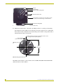
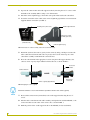
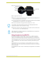
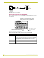
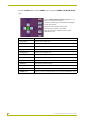
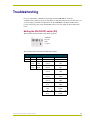
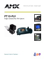
instruction manual
PT10-PLV
Single Camera Pan/Tilt System
C a me ra C on t ro l S y s te m s
Limited Warranty and Disclaimer
AMX Corporation warrants its products to be free from defects in material and workmanship under normal use for a
period of three years from date of purchase from AMX Corporation, with the following exceptions. Electroluminescent and LCD control panels are warranted for a period of three years, except for the display and touch overlay components which are warranted for a period of one year. Disk drive mechanisms, pan/tilt heads, power supplies,
modifications, MX Series products, and KC Series products are warranted for a period of one year. Unless otherwise
specified, OEM and custom products are covered for a period of one year. AMX Corporation software products are
warranted for a period of 90 days. Batteries and incandescent lamps are not covered.
This warranty extends to products purchased directly from AMX Corporation or an authorized AMX Corporation
dealer. Consumers should inquire from selling dealer as to the nature and extent of the dealer’s warranty, if any.
AMX Corporation is not liable for any damages caused by its products or for the failure of its products to perform,
including any lost profits, lost savings, incidental damages, or consequential damages. AMX Corporation is not liable
for any claim made by a third party or made by you for a third party.
This limitation of liability applies whether damages are sought, or a claim is made, under this warranty or as a tort
claim (including negligence and strict product liability), a contract claim, or any other claim. This limitation of liability cannot be waived or amended by any person. This limitation of liability will be effective even if AMX Corporation
or an authorized representative of AMX Corporation has been advised of the possibility of any such damages. This
limitation of liability, however, will not apply to claims for personal injury.
Some states do not allow a limitation of how long an implied warranty lasts. Some states do not allow the limitation
or exclusion of incidental or consequential damages for consumer products. In such states, the limitation or exclusion
of the Limited Warranty may not apply to you. This Limited Warranty gives you specific legal rights. You may also
have other rights that may vary from state to state. You are advised to consult applicable state laws for full determination of your rights.
EXCEPT AS EXPRESSLY SET FORTH IN THIS WARRANTY, AMX CORPORATION MAKES NO OTHER WARRANTIES, EXPRESS OR IMPLIED, INCLUDING ANY IMPLIED WARRANTIES OF MERCHANTABILITY OR FITNESS FOR A PARTICULAR PURPOSE. AMX CORPORATION EXPRESSLY DISCLAIMS ALL WARRANTIES NOT
STATED IN THIS LIMITED WARRANTY. ANY IMPLIED WARRANTIES THAT MAY BE IMPOSED BY LAW ARE
LIMITED TO THE TERMS OF THIS LIMITED WARRANTY.
Table of Contents
Table of Contents
PT10-PLV Single Camera Pan/Tilt System .............................................................1
PT10-PLV System Components ....................................................................................... 1
Single Camera Configuration with CMA-D2 (up to 25 m).................................................. 3
Installation and Wiring .............................................................................................5
Preparing the AXB-PT10 for Communication.................................................................... 5
Mounting the AXB-PT10.................................................................................................... 5
Mounting and Balancing the Camera/Lens ....................................................................... 7
Wiring Information for the AXB-PT10 ................................................................................ 9
Wiring Guidelines ................................................................................................................... 10
Using the AXlink connector for data and power ..................................................................... 11
Using the camera control RS-232 DB-9 connector ................................................................ 11
Wiring Information for the AXP-PLV................................................................................ 11
Using the AXlink mini-XLR connector for data and power ..................................................... 11
Wiring Information for the AXB-EM232 ........................................................................... 12
Putting It All Together...................................................................................................... 13
Suggested Wire Types For Custom Cables .................................................................... 13
AXlink - (local-area, low-power requirement) ......................................................................... 14
AXlink - (local-area, high-power requirement)........................................................................ 14
AXlink - (wide-area, local-power supply)................................................................................ 14
Using the AXP-PLV PosiTrack Video Pilot ...........................................................15
Using the AXP-PLV Touch Panel Program ..................................................................... 16
Troubleshooting .....................................................................................................19
Setting the RS-232 DIP switch (S2) ................................................................................ 19
Sony Technical Support ........................................................................................21
On the Web ..................................................................................................................... 21
Telephone Support.......................................................................................................... 21
Written Requests for Assistance ..................................................................................... 21
PT10-PLV Single Camera Pan/Tilt System
i
Table of Contents
ii
PT10-PLV Single Camera Pan/Tilt System
PT10-PLV Single Camera Pan/Tilt System
PT10-PLV Single Camera Pan/Tilt System
The AMX Single-Camera Control System delivers an advanced modular solution for precise
camera positioning applications. The main system component is the PosiTrack Pilot Video touch
panel (PosiPilot) that provides on-screen camera preview and controls the AXB-PT10 camera pan/
tilt head over a 4-wire (AXlink) data bus. The system can control up to six Sony® DXC-390/950
video cameras and store/recall up to 24 presets for each camera.
The PT10-PLV Single Camera Pan/Tilt System configuration is the building block for all systems
utilizing up to six cameras with Sony CMA-D2/D3 (camera adapters).
PT10-PLV System Components
AXP-PLV PosiTrack Pilot Video Panel Camera Controller
(PosiPilot)
The AXP-PLV PosiTrack Pilot Video Panel Camera Controller
(PosiPilot) provides integrated, programmable control of pan/tilt
heads and lenses. The integrated color video touch panel gives
you touch control and on-screen video monitoring.
AXB-PT10 Pan/Tilt Camera Head
This AXB-PT10 is a fully integrated camera-positioning controller
that provides on-board control of camera pan/tilt, and lens zoom/
focus/iris.
The AXB-PT10 power rating is 2 A @ 12 VDC. This power supply
must be local.
AXB-EM232 Enhanced Master/RS-232 Controller
The AXB-EM232 is the AMX Master Controller used in every configuration described in this manual, with the exception of the Multicamera configuration with CMA-D3 (up to 100 m). The multi-camera/D3 configuration uses an AXCENT3 Master Controller (which
has additional RS-232 ports).
PS2.8 Power Supply
The PS2.8 Power Supply provides up to 2.8 A of regulated power,
automatically switches for 110/220 V AC operation, and is overload protected.
The PS2.8 supplies power to both the AXB-EM232 and AXP-PLV.
PT10-PLV Single Camera Pan/Tilt System
1
PT10-PLV Single Camera Pan/Tilt System
PSN6.5 Power Supply
The PSN6.5 NetLinx Power Supply distributes switched-mode
12 VDC power @ 6.5 A to up to three AMX devices.
The PSN6.5 supplies power to the AXB-PT10 pan/tilt camera
head.
AXlink Bus Strip
The ABS AXlink Bus Strip is a 10-connector AXlink terminal strip
designed to simplify connecting multiple AXlink devices in an AMX
Control System.
Use the included double-sided tape to securely affix the unit to a
surface.
(PSN6.5)
2-pin captive-wire
CC-AXL AXlink Connection Cable (4-pin captive-wire to 4-pin
captive-wire, with 2-pin local power connector)
The AXlink cable is used in all configurations, and connects the
100’ (30.48 m)
AXB-PT10 to the Master Controller (either the AXB-EM232 or
AXCENT3). The 2-pin connector plugs into the PSN6.5 to provide
4-pin captive-wire
4-pin captive-wire
local power to the AXB-PT10.
(ABS Bus Strip)
(AXB-PT10)
CC-CAM Connection Cable (DB-9 to 8-pin mini DIN)
The CC-CAM cable connects the AXB-PT10 to the DXC-390/950
camera.
21" (53.34 cm)
DB-9 (on PT-10)
This cable is used with any camera powered by a CMA-D2.
CC-CAM Connection Cable (4-pin captive-wire to 8-pin mini
DIN)
8-pin mini-DIN
(on DXC Camera)
10’ (3.05 m)
The CC-CAM camera/lens cable connects the AXB-EM232 RS232 control to the CMA-D3 controllers.
This cable is used with cameras powered by a CMA-D3 when an
AXB-EM232 is used as the Master Controller.
8-pin mini-DIN
(on CMA-D3)
4-pin captive-wire
6" (15.24 cm)
PT10 to Camera Lens Cable (DB15 to 12-pin Hirosi)
This cable connects the Lens control assembly on the camera to
the LENS control port on the AXB-PT10.
DB-15
(on AXB-PT10)
12-pin Hirose
10’ (3.05 m)
PosiTrack Pilot to Master Cable
This cable connects the AXP-PLV PosiTrack Pilot to the Master
Controller (either the AXB-EM232 or AXCENT3).
2
4 stripped/tinned
wires
4-pin mini-XLR
(on AXP-PLV)
PT10-PLV Single Camera Pan/Tilt System
PT10-PLV Single Camera Pan/Tilt System
Single Camera Configuration with CMA-D2 (up to 25 m)
FIG. 1 shows a sample camera control application using a CMA-D2. The CMA-D2 provides power
to cameras at distances of up to 25 meters.
Sony camera
Sony CMA-D2
DB-9 to 8-pin mini-DIN
Preview
input
AMX AXP-PLV
AMX AXB-PT-10
2-pin captive-wire
AMX PSN6.5
Power Supply
AXlink
AXlink
AMX ABS (AXlink Bus Strip)
AXlink
AMX AXB-EM232 (rear view)
2-pin captive-wire
AMX PS2.8
Power Supply
FIG. 1 Sample camera control application using a CMA-D2 connection up to 25 m.
Power to the AXB-PT10 is supplied from the PSN6.5 Power Supply to the unused power pin on the
AXB-PT10's AXlink connector. Refer to FIG. 11 for more information about wiring the AXBPT10 AXlink connector.
AMX components in this additional-camera control system include:
• AXB-EM232
Master Controller
• AXB-PT10
Pan/Tilt Camera Head
• AXP-PLV
PosiTrack Pilot Video Panel Camera Controller
• PS2.8
Power Supply (for AXB-EM232)
• PSN6.5
Power Supply (for AXB-PT10)
• CC-AXL AXlink cable 100' (30.48 m) AXlink connection cable (4-pin captive-wire to 4-pin
captive-wire, with 2-pin power connector)
• CC-CAM cable
21" (53.34 cm) connection cable (DB-9 to 8-pin mini-DIN)
• PosiTrack Pilot to
Master Cable
10' (3.05 m) connection cable (4-wire to 4-pin mini-XLR)
• ABS
AXlink Bus Strip
PT10-PLV Single Camera Pan/Tilt System
3
PT10-PLV Single Camera Pan/Tilt System
Optional accessories:
4
• WM-CAM
Wall or Ceiling Mount Adapter (for AXB-PT10)
• PM-CAM
Pedestal Mount Adapter (for AXB-PT10)
• TM-CAM
Tripod Mount Adapter (for AXB-PT10)
• AC-RK
Accessory Rack Kit (for AXB-EM232, AXB-REL8 and AXB-AV2SM)
PT10-PLV Single Camera Pan/Tilt System
Installation and Wiring
Installation and Wiring
This section covers the steps necessary to connect and operate a PT10-PLV Single Camera Pan/Tilt
System. Digital encoders are installed on both the pan and tilt drives, allowing positional feedback
for presets, and to provide accurate speed control. Software adjustable stop limits are used to limit
the range of motion. Before continuing, verify that you have received the correct components for
your package. Refer to the PT10-PLV System Components section on page 1 for more information.
Preparing the AXB-PT10 for Communication
If you add one or more AXB-PT10s to your system, it will be necessary to set the AXlink Device
DIP switches on the additional PT10s. The AXB-PT10 that came with your kit was factory set as
AXlink device number 90. The first additional AXB-PT10 must be set to AXlink device 91, the
next one to device 92, and so on - up to 95 (for a maximum total of six PT10s).
The AXlink Device DIP switch is located beneath the round cover on the back of the AXB-PT10.
FIG. 2 shows the location of the DIP switch and each of the possible AXlink Device DIP switch
settings for additional AXB-PT10s.
AXlink Device
DIP switch
Device #90
(base AXB-PT10)
Device #93
Device #91
Device #94
Device #92
Device #95
FIG. 2 AXB-PT10 (rear view) and AXLink Device DIP switch settings for devices 90 - 95.
Mounting the AXB-PT10
Mount the AXB-PT10 to a flat horizontal surface, either upright or inverted.
Do not mount a PosiTrack unit in any location where the motion of the camera is obstructed by any
object, or handle or lift the AXB-PT10 by the camera cradle. Doing so may damage internal
components.
1. Select a surface that can support the combined weight of the AXB-PT10 (8.00 lbs./3.63 kg),
camera/lens (10 lbs./4.54 kg), and control cables. Some support surfaces include the WMCAM, PM-CAM, and TM-CAM mounts available for use with these units.
2. Locate the external white position markers located on the pan and tilt axis. The position
markers must align with the pan and tilt axis in order to be considered in the home position.
FIG. 3 shows the camera cradle attachment in the center position.
PT10-PLV Single Camera Pan/Tilt System
5
Installation and Wiring
Tilt Hub
Central tilt-axis
Camera cradle mounting holes
Camera points this way
Position markers, located on the outer surfaces, mark
.
the center for the vertical range of camera motion.
Pan Hub (mounting-plate)
FIG. 3 Center position for the camera cradle attachment (side view)
3. Mount the PosiTrack unit to a flat surface by drilling four holes, according to the mountingplate dimensions shown in FIG. 4. Secure the unit to the surface using four 1/4" x 20 machine
bolts and lock washers. Ensure that the external white position marker, on the pan drive hub, is
inside the desired camera rotation range.
Camera points this way when the pan drive is in the center
of it's range of motion (Home position).
Position marker
(on the outer surface)
3.453" (87.7 mm)
3.00" BHC
(76.20mm)
3.45"
(87.7 mm)
FIG. 4 Mounting-plate dimensions
The PT10 can be mounted to camera mounts such as the TM-CAM, WM-CAM, and PM-CAM
(Pedestal mount) as shown in FIG. 5.
6
PT10-PLV Single Camera Pan/Tilt System
Installation and Wiring
Cradle support bracket
Camera mount assembly
Pedestal mount
Wire
tie-mount
FIG. 5 PT10 and pedestal mount
The Camera/Lens cradle can be mounted on either side of the cradle support bracket.
Mounting and Balancing the Camera/Lens
The camera/lens assembly should be mounted so the tilt axis is capable of going through the optical
axis of the camera, assuming the optical centerline is between ½" (12.70 mm) and 5" (127.00 mm)
above the mounting plane of the camera lens. The mounting platform (camera mount) allows the
camera/lens to be mounted with its center of gravity on the tilt axis. The maximum weight of the
camera/lens assembly is 10 lbs. (4.54 kg). The camera cradle is mounted to the Tilt Hub. FIG. 6
shows the dimensions of the Tilt Hub.
0.75"
(19.05 mm)
0.75"
(19.05 mm)
0.75"
(19.05 mm)
0.25"
(6.35 mm)
0.25"
(6.35 mm)
0.00"
Camera points in
this direction
0.75"
(19.05 mm)
0.56" (39.62 mm)
FIG. 6 Tilt Hub dimensions
To mount and balance the camera/lens:
Do not lift the PT10 by the Camera/Lens cradle as this procedure damages internal components.
1. Remove the camera/lens cradle assembly by removing the four ½" screws and washers from
the tilt hub.
PT10-PLV Single Camera Pan/Tilt System
7
Installation and Wiring
2. Separate the camera mount and cradle support bracket by removing the two ½" screws on the
underside of the assembly (FIG. 7) using a 3/32 Allen wrench.
3. Install the camera alignment peg to the mount at the position that best fits the camera/lens.
4. Secure the camera/lens to the cradle (at the camera alignment peg) with the screw and fastener
supplied with the camera/lens (see FIG. 7).
Mounting holes (three sets)
Cradle support bracket
Camera/Lens cradle
assembly (side view)
Camera mount
(underside view)
Camera alignment peg
FIG. 7 Camera/Lens cradle assembly (camera mount and lens mount)
5. Determine (and note) the center of gravity for the camera by using your finger to balance the
entire camera/lens and mount. The center of gravity is the location on the long axis of the
camera/lens assembly around which the camera balances.
6. Place the camera/mount in the appropriate location along the cradle support bracket so the
camera's center of gravity aligns with the horizontal tilt-axis, as shown in FIG. 8.
Horizontal
tilt-axis
Camera and lens
Camera/lens
and mount
Center of gravity (approximate)
FIG. 8 Aligning the center of gravity
Mount the camera as close to the Tilt Hub as possible to obtain a true center of gravity.
7. Re-attach the camera mount (camera/lens) to the cradle support bracket using the two ½"
screws.
8. Take the entire camera/mount and cradle assembly, and align the lens with the Tilt Hub, so the
vertical-axis intersects the center of the camera's iris, as shown in FIG. 9.
9. Mark the position of the cradle support bracket on the Tilt Hub (for later attachment).
8
PT10-PLV Single Camera Pan/Tilt System
Installation and Wiring
Marker points
Iris
Vertical tilt-axis
FIG. 9 Iris alignment with vertical tilt-axis
10. Remove the camera/lens and mount piece from the support bracket by unscrewing the two ½"
screws on the underside of the camera mount.
11. Secure the support bracket to the Tilt Hub (at the same position marked for the iris alignment)
on the PT10 with some or all of the four ½" screws and washers.
12. Secure the camera/mount to the support bracket by using the two ½" screws.
The camera/lens cradle can be mounted on either side of the cradle support bracket. This is
especially useful when the camera is mounted to the ceiling.
13. Support the weight of the camera cables with a wire tie attached to the wire tie mount on the
lower corner of the face of the AXB-PT10 (FIG. 10).
When applying power to the AXB-PT10, adjust the soft-set pan/tilt-limit stops to a safe position to
prevent camera or AXB-PT10 damage.
Wiring Information for the AXB-PT10
Each PosiTrack Controller has an RS-232 DB-9 connector, lens control DB-15 high-density
connector, and an AXlink 4-pin connector. Always provide enough cable to accommodate the
desired range of motion for the PosiTrack unit and its camera/lens. The Lens Power switch on the
control panel (FIG. 10), removes any power noise on the incoming video by turning power On/Off
to Pin 1 of the DB-15 lens control connector when the camera/lens is powered from a separate
supply.
The AXB-PT10 receives all power through the +12 VDC and GND connections on the 4-pin
AXlink connector. The portion of the power directed toward the pan and tilt motors is fused. The
fuses are self-resetting.
The AXB-PT10 power rating is 2 amps @ 12 VDC. This power supply must be local. See FIG. 11
for details.
PT10-PLV Single Camera Pan/Tilt System
9
Installation and Wiring
Camera control RS-232 DB-9
(male) connector
AXlink 4-pin (male) connector
FIG. 10 Side view of the AXB-PT10 showing the location of the AXlink connector.
When applying power to the AXB-PT10, adjust the soft-set pan/tilt-limit stops to a safe position to
prevent camera or AXB-PT10 damage.
Wiring Guidelines
The PosiTrack Controller requires local +12 VDC power (optional) to operate properly. The
maximum wiring distance between the power supply and the PosiTrack Controller is determined by
power consumption, supplied voltage, and the wire gauge used for the cable. The following table
lists wire sizes and the maximum lengths allowable between the PT10 and the power supply. The
maximum wiring lengths are based on a minimum of 13.5 VDC, available at the power supply
output.
To reduce the possible effects of ground loop noise in the video, use a single-source power supply
mounted within distances specified below.
Wiring Specifications - PT10
18 AWG
29.34 feet (8.94 meters)
20 AWG
18.56 feet (5.66 meters)
22 AWG
11.57 feet (3.53 meters)
24 AWG
7.30 feet (2.23 meters)
Do not connect power to the PosiTrack Controller until the wiring is complete. If using an optional
+12 VDC power supply, apply power to the AXB-PT10 only after installation is complete.
The PosiTrack Controller is powered from an optional local power supply. The wiring distances
listed for the AXB-PT10 in the above table are based on a +12 VDC power supply and are capable
of 2 amps (continuous) with a maximum current of 20 amps. The PosiTrack unit provides power
outputs for the camera/lens combination.
10
PT10-PLV Single Camera Pan/Tilt System
Installation and Wiring
Using the AXlink connector for data and power
To use the AXlink 4-pin connector for data communication with the AXB-EM232 and power
transfer from the PSN6.5 power supply, the incoming PWR and GND cable from the PSN6.5 must
be connected to the AXlink cable connector going to the AXB-PT10. FIG. 11 shows how the power
cable from the PSN6.5 is used to power the AXB-PT10, and the GND cable is connected to the
existing GND cable on the AXlink cable coming from the AXB-EM232. Always use a local power
supply to power the AXB-PT10. This is the configuration of the supplied CC-AXL AXlink
Connection Cable.
PWR+
GND-
Local +12VDC power supply
(coming from the PSN6.5)
2-pin power connector
PWR+
AXP/TX
PWR+
AXP/TX
AXM/RX
AXM/RX
GND-
GNDFIG. 11 AXlink connector and local +12 VDC power supply wiring diagram
Using the camera control RS-232 DB-9 connector
The RS-232 DB-9 (male) connector on the AXB-PT10 connects to the camera head's RS-232
connector. The following table lists the pinouts and shows the pin configuration for the DB-9
connector.
Camera Control DB-9 RS-232 Connector Pinouts
Pin
Signal
Pin
Signal
1
N/A
6
N/A
2
RXD
7
RTS
3
TXD
8
CTS
4
N/A
9
N/A
5
GND
Pin 1
Pin 9
Wiring Information for the AXP-PLV
The AXP-PLV comes with a mini-XLR cable.
Using the AXlink mini-XLR connector for data and power
Wire the Master Controller's AXlink connector to the mini-XLR connector (male) on the rear panel
of the AXP-PLV for data and 12 VDC power as shown in FIG. 12.
PT10-PLV Single Camera Pan/Tilt System
11
Installation and Wiring
To Master Controller
To AXP-PLV
1 GND- (black)
2
1
4
2 AXM (green)
3
3 AXP (white)
4 PWR+ (red)
4 - PWR+ (red)
3 - AXP (white)
2 - AXM (green)
1 - GND- (black)
FIG. 12 Mini-XLR connector wiring diagram
Wiring Information for the AXB-EM232
FIG. 13 shows the front and rear view of the AXB-EM232 and describes the features relevant to
this configuration.
AXlink LED - The green AXlink LED blinks to indicate
AXlink communication activity, power, and data status,
according to the descriptions listed below.
AXlink 4-pin captive-wire connector for data
and power (to AXB-PT10 and AXP-PLV)
2-pin captive-wire 12 VDC
power connector (from
PS2.8)
FIG. 13 Front and rear views of the AXB-EM232
The following table describes the blink patterns for the front panel AXlink LED.
AXlink Blink Patterns
12
One blink/second
Indicates that power is active and AXlink communication is functioning.
Two blinks/second
Indicates that power is active and AXlink communication is functioning, and that
the devices specified in the master program do not match the devices found. This
will be the blink pattern normally seen with PosiPilot camera control system
because the master program has the ability to control more devices than are normally present.
Three blinks/second
Indicates that there is an AXlink communication error.
Full On
Indicates that there is either no AXlink activity or that the AXCESS program is not
loaded.
PT10-PLV Single Camera Pan/Tilt System
Installation and Wiring
Putting It All Together
1. Connect the green 2-pin PS2.8 power connector to the rear of the AXB-EM232.
2. Make AXlink connections:
a. Connect the AXlink port on the AXB-EM232 to Connector 1 on the ABS.
b. Connect the AXlink port on the AXB-PT10 to open connector on the ABS.
c. Connect the mini-XLR port on the AXP-PLV to an open connector on the ABS.
3. Connect the CC-AXL 2-pin power connector to the PSN6.5 power supply.
When applying power to the AXB-PT10, adjust the soft-set pan/tilt-limit stops to a safe position to
prevent camera or AXB-PT10 damage.
4. Connect the lens control cable from the side of the lens to the 6-pin LENS connector on the
rear of the camera.
5. Connect the DB-9 port on the AXB-PT10 to the 8-pin mini-DIN REMOTE connector on the
rear of the camera (for systems where the camera is located within 25 m of the CMA-D2).
For systems where the camera is located over 25 m, use the 4-pin captive-wire to mini 8-pin
DIN cable to connect the CMA-D3 to the AXB-EM232 (RS-232 port 1 on the rear panel of the
AXB-EM232). The CMA-D3 can be located up to 100 m from the camera.
6. Use a BNC cable to connect the VIDEO OUT port on the rear of the camera to the BNC
connector on the rear of the AXP-PLV.
7. Connect the CMA-D2 to the DC IN/VBS port on the rear of the camera.
8. Verify there are no obstructions in the horizontal or vertical paths of the attached camera on the
AXB-PT10.
For best performance, mount the AXB-EM232 as close to the CMA-D2 as possible.
9. Plug in the PSN6.5, PS2.8, and CMA-D2 power supplies to their respective outlets.
10. Allow the AXP-PLV touch panel software approximately 20 seconds for initialization and selfcalibration before beginning use.
Do not move the joystick or the focus wheel while the AXP-PLV is displaying its initialization
page. Self-calibration is in progress.
11. Select the video input for camera one by pressing the Camera Station 1 pushbutton located on
the right side of the AXP-PLV touch panel.
Suggested Wire Types For Custom Cables
AXlink is a control network that uses four wires to carry data and power to all remote devices in the
system. Two wires carry a balanced-line data signal; the other two provide ground and +12 VDC
power. Large distributed systems that use long AXlink runs with a maximum of 3,000 feet
(914.4 m) should use low-capacitance (12-14 pF/ft) shielded twisted pair cable.
!
The length of an AXlink wire run is equal to the total length of wire used; a star run made
of one 300' section and six 50' sections equals one 600' AXlink line.
PT10-PLV Single Camera Pan/Tilt System
13
Installation and Wiring
!
AXlink data lines (AXM and AXP) are designed for balance-line operation; wire the data
lines in the same twisted pair.
!
Use a shielded cable for best results, both to reduce electronic interference radiated by
adjacent wiring and to eliminate noise from AXlink cabling to adjacent audio cabling.
If you find that the included 100' (30.48 m) AXlink cables are not long enough for your application,
use the wire types suggested below to make custom cables.
AXlink - (local-area, low-power requirement)
22/24 AWG 4-conductor cables can be used for short wiring runs.
!
Level 3, 4, or 5 unshielded, twisted pair
!
Belden 8102, 2 twisted pair, 1 shield 12 pF/ft, PVC and plenum cable available.
AXlink - (local-area, high-power requirement)
Large systems that power many bus controllers or touch panels should use a heavier gauge wire to
handle DC power.
!
Liberty Wire and Cable AMX-2S22218 AXlink Cable, one shielded, twisted pair 22
AWG, 12.5 pF/ft, two 18 AWG, PVC and plenum cable available.
AXlink - (wide-area, local-power supply)
In this type of system, power is rarely distributed over the AXlink bus; local power supplies are
used for each controller or linked system.
!
14
West Penn D2401 1 twisted pair, 1 shield 14 pF/ft, plenum cable available.
PT10-PLV Single Camera Pan/Tilt System
Using the AXP-PLV PosiTrack Video Pilot
Using the AXP-PLV PosiTrack Video Pilot
Color video touch panel for video
preview and control interface
External pushbuttons:
(RM-C350 and
RM-C950 functions)
External pushbuttons:
(Camera Station 1-6 select)
Pan/tilt/zoom
control joystick
Speed control
knob
Iris control
knob
Focus wheel
FIG. 14 AXP-PLV PosiTrack Video Pilot camera controller
The control features of the AXP-PLV PosiTrack Video Pilot camera controller are described below:
Pan/tilt/zoom control joystick:
Use the joystick to control pan and tilt movements.
Rotate the top of the joystick left and right to zoom in and out.
Speed control knob:
Rotate to control the speed of the pan and tilt movements.
Iris control knob:
Rotate to open and close the camera's iris.
Focus wheel:
Rotate to control focus on the camera.
External pushbuttons (left side):
This set of six pushbuttons closely duplicate the buttons on Sony RMC350/950 camera controllers.
Menu:
Function up/down:
ABB:
Data up/down:
CAMERA STATION Select
External pushbuttons
(right side):
PT10-PLV Single Camera Pan/Tilt System
Press to open the camera's on-screen menu.
Press to scroll up/down through the camera menu options.
Press to set Automatic Black Balance. This function is only active when
camera menus are not being displayed.
Once you have selected a camera menu option, press the Data up/
down buttons to scroll through the available choices.
AWB:
Press to set Automatic White Balance. This function is only active
when camera menus are not being displayed.
Enter:
Press to make a selection from the menu.
This set of six pushbuttons allows you select which camera (1-6) you
are controlling. The Camera Station selection indicators along the right
edge of the touch panel light to indicate which camera is currently
selected.
15
Using the AXP-PLV PosiTrack Video Pilot
Video preview/touch panel
screen:
The touch panel screen displays a video preview and gives you access
to various control features such as store/recall presets, gain and detail
settings and the camera configuration options via the touch panel buttons.
For details on using the touch panel buttons, refer to the Using the
AXP-PLV Touch Panel Program section below.
Using the AXP-PLV Touch Panel Program
This section describes the touch panel pages, and their buttons. When the AXP-PLV is powered up,
an initialization screen appears for several seconds. Then, the CAMERA page (FIG. 15) appears:
Preset buttons 1-8
Camera Station
selection indicators 1-6
FIG. 15 CAMERA page
Simply touch the panel to activate the buttons and sliders on the panel.
16
• Preset buttons 1-8
You can store and recall up to 24 presets for zoom, focus, iris, pan/tilt and
speed settings. By default, preset buttons 1-8 are shown.
• mode button
Touch to display preset buttons 9-16. Press the mode button again to display
preset buttons 17-24.
• store button
Touch a preset button, then touch the store button to store the camera's current pan/tilt position, zoom, focus, speed and iris settings as a preset.
• recall button
Touch a preset button, then touch the recall button to recall the pan/tilt position,
zoom, focus, speed and iris settings saved for the selected preset.
• speed slider control
Use this slider control to adjust the preset pan/tilt speed.
• next button
Touch to flip to the next touch panel page (in this case, the MENU page).
• iris button
Touch to toggle between automatic and manual iris control. If it is set to Manual, you will use the iris control knob on the side of the AXP-PLV to open/close
the iris.
• bars button
Touch to toggle a color bar display on the screen.
• config button
Touch to open the CAMERA CONFIGURATION page, where you can configure
a camera for your system.
• Camera Station
selection indicators 1-6
These indicators light to indicate which camera is currently selected (via the
CAMERA STATIONS 1-6 external pushbuttons).
PT10-PLV Single Camera Pan/Tilt System
Using the AXP-PLV PosiTrack Video Pilot
Press the NEXT button in the CAMERA page to open the CAMERA MENU page. Use the
CAMERA MENU page to view the camera's menu page.
While the CAMERA MENU page is open, press the external
button labeled MENU (to the left of the touch panel). The
camera's menu page is displayed on the panel. The items in
the MENU page will vary, depending on the camera
installed, so consult the Sony literature for details on your
camera.
• next button
Touch to flip to the next touch panel page (in this case, the CAMERA
ADJUSTMENT page).
• DEFAULT button
Touch to return the selected camera menu item to its default setting.
Use the CAMERA ADJUSTMENT page slider bars to:
•Adjust the master pedestal setting.
•Adjust the detail setting.
•Adjust the master gain setting.
•Adjust the red gain setting.
•Adjust the blue gain setting.
When you press any of these slider bars, a secondary page
is opened that shows only the selected slider bar, leaving
the rest of the screen free to view the preview picture.
• next button
Touch to flip to the next touch panel page (in this case it flips back to the
CAMERA page).
• bars button
Touch to toggle a color bar display on the screen.
• default button
Touch to restore the camera to its default master pedestal, detail and gain settings. (This is the same as pressing the Data UP and DOWN buttons simultaneously on the Sony RM-C950).
PT10-PLV Single Camera Pan/Tilt System
17
Using the AXP-PLV PosiTrack Video Pilot
Press the CONFIG button on the CAMERA page to open the CAMERA CONFIGURATION
page:
Use the CAMERA CONFIGURATION page buttons to configure a new camera to the system:
•Set and/or clear limit stops for pan up/down and left/right.
•Set the home position.
•Reverse the pan orientation on the joystick.
•Reverse the tilt orientation on the joystick.
•Enter the touch panel's SETUP screen (for system
administrators only).
18
• set home button
Touch to set the home position.
• set up button
Touch to set the up limit stop.
• clear up button
Touch to clear the up limit stop.
• set down button
Touch to set the down limit stop.
• clear down button
Touch to clear the down limit stop.
• set right button
Touch to set the right limit stop.
• clear right button
Touch to clear the right limit stop.
• set left button
Touch to set the left limit stop.
• clear left button
Touch to clear the left limit stop.
• back button
Touch to flip to the previous page.
• reverse pan button
Touch to reverse the current pan orientation on the joystick.
• reverse tilt button
Touch to reverse the current tilt orientation on the joystick.
• SETUP button
Touch to access the touch panel Setup screen (for system administrators only).
PT10-PLV Single Camera Pan/Tilt System
Troubleshooting
Troubleshooting
If you are experiencing communication problems with the AXB-EM232, check the
communications settings for the device. The RS-232 communication parameters for this device are
set via the eight-position RS-232 DIP switch. On the AXB-EM232, the RS-232 DIP switch is
located on the front panel. Verify that this DIP switch is set to the default positions indicated in
below.
Setting the RS-232 DIP switch (S2)
This describes the RS-232 DIP switch default positions:
• 9,600 baud
• No parity
• 8 bits
• 1 stop bit
The following table lists the RS-232 DIP switch settings:
RS-232 DIP Switch (S2) Settings
Position
1
2
3
Function Stop Bits Data Bits
Off
Off
2 bits
7 bits
On
On
1 bit
8 bits
4
5
6
Off
Off
Off
On
Off
Off
Off
On
On
Off
On
On
On
Off
On
On
Parity
Off
Off
Off
On
On
Off
Off
On
On
None
PT10-PLV Single Camera Pan/Tilt System
Off
On
Off
Off
On
Off
On
9,600
Odd
On
On
4,800
Even
Off
Off
2,400
Unused
On
Off
1,200
Unused
Off
Off
600
Unused
On
Off
300
Unused
Off
8
Baud Rate
Unused
On
7
On
On
19,200
On
On
38,400
19
Troubleshooting
20
PT10-PLV Single Camera Pan/Tilt System
Sony Technical Support
Sony Technical Support
On the Web
You can contact the Technical Assistance Network (TAN) on the Internet:
!
http://bpgprod.sel.sony.com/infosupport.bpg
Telephone Support
For dedicated phone support (available from 8:30 a.m. to 8:00 p.m. Eastern time, Monday through
Friday):
!
(201) 833-5333
Written Requests for Assistance
Sony's Business Information Center (BIC) serves as a "virtual reception desk" for the Broadcast
and Professional Group. Staffed with full-time agents, the center is the focal point of contact for
any Broadcast and Professional Group inquiry. The BIC is designed to provide general information,
including product specifications, literature and list prices to inquiring callers.
!
Tel: 1-800-686-SONY
!
Email: http://bpgprod.sel.sony.com/cic.htm
PT10-PLV Single Camera Pan/Tilt System
21
Sony Technical Support
22
PT10-PLV Single Camera Pan/Tilt System
Sony Technical Support
PT10-PLV Single Camera Pan/Tilt System
25
brussels • dallas • los angeles • mexico city • philadelphia • shanghai • singapore • tampa • toronto • york
3000 research drive, richardson, TX 75082 USA • 469.624.8000 • 800.222.0193 • fax 469.624.7153 • technical support 800.932.6993
048-004-2381 08/01 ©2001 AMX Corporation. All rights reserved. AMX, the AMX logo, the building icon, the home icon, and the light bulb icon are all trademarks of AMX Corporation.
AMX reserves the right to alter specifications without notice at any time.
AMX reserves the right to alter specifications without notice at any time.