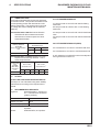
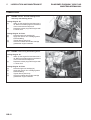
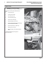
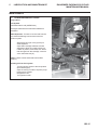
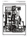
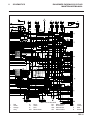
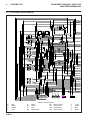
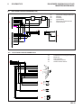
1
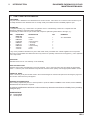
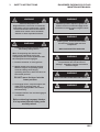
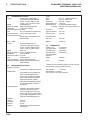
24286G-GB (rev.6)
®
Maintenance Manual
Parkway 2250 Plus
Series: WB - Engine type: Kubota V1505
Product code: LGNN040
Series: CT - Engine type: Ford VSG413
Product code: LGNN100
WARNING: If incorrectly used this machine can cause severe
injury. Those who use and maintain this machine should be
trained in its proper use, warned of its dangers and should
read the entire manual before attempting to set up, operate,
adjust or service the machine.
RJL 100 September 2009
© 2009, Ransomes Jacobsen Limited. All Rights Reserved
1
CONTENTS
RANSOMES PARKWAY 2250 PLUS
MAINTENANCE MANUAL
2
INTRODUCTION
2.1
PRODUCT IDENTIFICATION .......................................................................................... 2
2.2
SPARES STOCKING GUIDE .......................................................................................... 2
2.3
HOW TO USE THE PARTS MANUAL ............................................................................ 3
3
SAFETY INSTRUCTIONS
3.1
OPERATING INSTRUCTIONS ........................................................................................ 4
3.2
SAFETY SIGNS ............................................................................................................. 4
3.3
STARTING THE ENGINE ................................................................................................ 4
3.4
DRIVING THE MACHINE ................................................................................................ 4
3.5
TRANSPORTING .......................................................................................................... 4
3.6
LEAVING THE DRIVING POSITION ............................................................................... 4
3.7
SLOPES ....................................................................................................................... 5
3.8
BLOCKED CUTTING CYLINDERS ................................................................................. 5
3.9
ADJUSTMENTS, LUBRICATION AND MAINTENANCE ................................................. 5
4
SPECIFICATION
4.1
ENGINE SPECIFICATION ............................................................................................... 8
4.2
MACHINE SPECIFICATION ........................................................................................... 8
4.3
DIMENSIONS ................................................................................................................ 8
4.4
VIBRATION LEVEL ....................................................................................................... 9
4.5
SLOPES ....................................................................................................................... 9
4.6
RECOMMENDED LUBRICANTS .................................................................................... 9
4.7
CUTTING PERFORMANCE ............................................................................................ 9
4.8
CUTTING PERFORMANCE (AREA) ............................................................................... 9
5
LUBRICATION & MAINTENANCE
5.1
LUBRICATION AND MAINTENANCE CHART - DIESEL ................................................ 10
5.2
LUBRICATION AND MAINTENANCE CHART - LPG ...................................................... 11
5.3
ENGINE - DIESEL: FIRST 50 AND EVERY 200 WORKING HOURS. ............................. 12
5.3.1 ENGINE - LPG: EVERY 200 WORKING HOURS. ......................................................... 12
5.4
MACHINE: LUBRICATION WEEKLY OR EVERY 40 WORKING HOURS. ..................... 13
5.5
MACHINE: LUBRICATION EVERY 400 WORKING HOURS .......................................... 14
5.6
MACHINE: LUBRICATION EVERY 800 WORKING HOURS .......................................... 14
5.7
HYDRAULIC TEST POINTS. ......................................................................................... 14
5.8
ENGINE MAINTENANCE - DIESEL EVERY 100 HOURS ............................................... 15
5.9
ENGINE MAINTENANCE - DIESEL EVERY 400 HOURS ............................................... 16
5.9.1 ENGINE MAINTENANCE -LPG EVERY 400 HOURS ..................................................... 16
5.10 ENGINE MAINTENANCE - DIESEL EVERY 400 HOURS ............................................... 17
5.11 MACHINE MAINTENANCE ........................................................................................... 17
5.12 END OF SEASON OR WHEN REQUIRED ..................................................................... 18
5.12.1 END OF SEASON OR WHEN REQUIRED LPG ENGINE ................................................ 19
6
ADJUSTMENT
6.1
SPEED LIMITER. .......................................................................................................... 20
6.2
ALTERNATOR/WATER PUMP - DIESEL ....................................................................... 20
ALTERNATOR/WATER PUMP/FAN - LPG ..................................................................... 20
6.3
COOLING FAN BELT - DIESEL ..................................................................................... 20
6.4
BACKLAPPING ............................................................................................................ 21
7
TROUBLESHOOTING
7.1
TROUBLESHOOTING - DIESEL ................................................................................... 22
7.1
TROUBLESHOOTING - LPG ........................................................................................ 23
7.2
LPG FAULT FINDING CHART ........................................................................................ 26
8
SCHEMATICS
8.1
HYDRAULIC CIRCUIT ................................................................................................... 28
8.2
ELECTRICAL CIRCUIT ENGINE AND SAFETY DIESEL ................................................. 30
8.3
ELECTRICAL CIRCUIT MAIN LPG ................................................................................ 32
8.4
ELECTRICAL CIRCUIT ENGINE LPG-1 ......................................................................... 34
8.5
ELECTRICAL CIRCUIT GOVERNOR LPG ..................................................................... 35
8.6
ELECTRICAL CIRCUITENGINE LPG-2 .......................................................................... 35
8.7
ELECTRICAL CIRCUIT INSTRUMENTS & CONTROLS ................................................ 36
8.8
ELECTRICAL CIRCUIT FUSES AND RELAYS - DIESEL ................................................ 38
8.9
ELECTRICAL CIRCUIT FUSES AND RELAYS - LPG ..................................................... 40
GB-1
2
RANSOMES PARKWAY 2250 PLUS
MAINTENANCE MANUAL
INTRODUCTION
2.1
PRODUCT IDENTIFICATION
A
B
C
D
E
2.2
Machine Name
Serial Number
Year of Manufacture
Machine Weight
Engine Power
Spares Stocking Guide
To keep your equipment fully operational and productive, Ransomes suggests you maintain a stock of the more
commonly used maintenance items. We have included part numbers for the additional support materials and
training aids.
Service Parts
Part No
Description
Part No.
Description
008196060
Engine Oil Filter - Diesel 13351-43011
Inline Fuel Filter - Diesel
1070523
Engine Oil Filter - LPG
178078
Engine Fuel Filter - Diesel
008089620
Hydraulic Filter
1120825
Spark Plug - LPG
2198147-01
Air Cleaner Element
N203438
Fan Belt - LPG
0082971910
Ignition Switch
Service Support Material
GB-2
Part No
Description
Part No.
Description
97898-03340
Kubota Engine Parts Manual 194265
Ford Engine Parts Manual
16622-8916-2
Kubota Engine Operators
Manual
D S L58221
Ford LPG Engine Operators
Manual
97897-00880
Kubota Engine Service
Manual
24564G
Ford Engine Service Manual
2
INTRODUCTION
2.3
RANSOMES PARKWAY 2250 PLUS
MAINTENANCE MANUAL
HOW TO USE THE PARTS MANUAL
ITEM NUMBER
Each part which is identified in the illustrations has an item number. Parts which do not have an item number may not
be readily identified in the illustration but are usually closely associated with the immediately adjacent part.
ASSEMBLIES
A complete assembly, e.g. a wheel motor or hydraulic motor or roll assembly, is listed as a complete item with
subsequent individual components listed separately.
The assembly is listed under it's part number with component parts being listed offset to the right, e.g:ITEM
1
2
3
4
5
6
7
*
RANSOMES
PART NO.
LMSD798
MBB4490
LMSD926
MBB6851
H009116
MBB2356
A224016
A122192
DESCRIPTION
QTY
REMARKS
Roll Assy.
• Tube
• End Cap Assy.
• • End Cap
• • Bearing
• Seal Housing
• Seal
Screw
1
1
2
1
1
1
2
2
ALL MACHINES
It may not be possible to illustrate every item. With certain items purchased from outside suppliers some component
parts may not be available from Ransomes and may need to be specially ordered from the supplier e.g. Volvo hydraulic
motor components.
QUANTITIES
Quantities shown are for one assembly or sub-assembly.
USING THE PARTS LIST
Determine the function and application of the part required. Turn to the main index page and select the appropriate
section. Locate the part on the illustration and parts list and read off the quantity from the appropriate MODEL column.
NUMERICAL INDEX
This is a summary of all part numbers used in the manual arranged in numerical sequence and showing the page and
item number under which the parts appear.
ORDERING OF SPARE PARTS
When ordering replacement parts, it is most important to quote the SERIAL NUMBER of the machine, PART NUMBER,
DESCRIPTION and QUANTITY required.
Any arbitrary modifications carried out on this machine may relieve the manufacturer of liability for any resulting
damage or injury.
ABBREVIATIONS
N/A Not Available
AR As Required
GB-3
3
RANSOMES PARKWAY 2250 PLUS
MAINTENANCE MANUAL
SAFETY INSTRUCTIONS
•
This safety symbol indicates important safety
messages in this manual. When you see this
symbol, be alert to the possibility of injury, carefully
read the message that follows, and inform other
operators.
•
3.1 OPERATING INSTRUCTIONS
•
Ensure that the instructions in this book
are read and fully understood.
•
No person should be allowed to operate
this machine unless they are fully
acquainted with all the controls and the
safety procedures.
•
Never allow children or people unfamiliar
with these instructions to usethis
machine. Local regulations may restrict
the age of the operator.
•
3.2 SAFETY SIGNS
•
It is essential all safety labels are kept
legible, if they are missing or illegible they
must be replaced. If any part of the
machine is replaced and it originally
carried a safety label, a new label must be
affixed to the replacement part. New
safety labels are obtainable from
Ransomes dealers.
•
3.3 STARTING THE ENGINE
•
Before starting the engine check that the
brakes are applied, drives are in neutral,
guards are in position and intact, and
bystanders are clear of the machine.
•
Do not run the engine in a building without
adequate ventilation.
3.4 DRIVING THE MACHINE
•
Before moving the machine, check to
ensure that all parts are in good working
order, paying particular attention to
brakes, tyres, steering and the security of
cutting blades.
•
Replace faulty silencers, mow only in
daylight or good artificial light
•
Always observe the Highway Code both on
and off the roads. Keep alert and aware at
all times. Watch out for traffic when
crossing or near roadways.
•
Stop the blades rotating before crossing
surfaces other than grass.
GB-4
•
•
•
•
•
Remember that some people are deaf or
blind and that children and animals can
be unpredictable.
Keep travelling speeds low enough for an
emergency stop to be effective and safe
at all times, in any conditions.
Remove or avoid obstructions in the area
to be cut, thus reducing the possibility of
injury to yourself and/or bystanders.
When reversing, take special care to
ensure that the area behind is clear of
obstructions and/or bystanders. DO
NOT carry passengers.
Keep in mind that the operator or user is
responsible for accidents or hazards
occurring to other people or their
property.
When the machine is to be parked,
stored or left unattended, lower the
cutting means unless the transport locks
are being used.
While mowing, always wear substantial
footwear and long trousers. Do not
operate the equipment when barefoot or
wearing open sandals.
Check the grass catcher frequently for
wear or deterioration. After striking a
foreign object. Inspect. the lawnmower
for damage and make repairs before
restarting and operating the equipment.
If the machine starts to vibrate
abnormally, check immediately.
3.5 TRANSPORTING
•
Ensure that the cutting units are
securely fastened in the transport
position. Do not transport with cutting
mechanism rotating.
•
Drive the machine with due consideration
of road and surface conditions, inclines
and local undulations.
•
Sudden decelerating or braking can
cause the rear wheels to lift.
•
Remember that the stability of the rear of
the machine is reduced as the fuel is
used.
3.6 LEAVING THE DRIVING POSITION
•
Park the machine on level ground.
•
Before leaving the driving position, stop
the engine and make sure all moving
parts are stationary. Apply brakes and
disengage all drives. Remove the starter
key.
3
RANSOMES PARKWAY 2250 PLUS
MAINTENANCE MANUAL
SAFETY INSTRUCTIONS
3.7 SLOPES
TAKE EXTRA CARE WHEN WORKING ON
SLOPES
•
Local undulations and sinkage will change
the general slope. Avoid ground conditions
which can cause the machine to slide.
•
Keep machine speeds low on slopes and
during tight turns.
•
Sudden decelerating or braking can cause
the rear wheels to lift. Remember there is
no such thing as a “safe” slope.
•
Travel on grass slopes requires particular
care.
DO NOT USE ON SLOPES GREATER THAN 15°
IMPORTANT: When working on any slope set the
weight transfer, if fitted to its maximum (+) setting.
3.8 BLOCKED CUTTING CYLINDERS
•
Stop the engine and make sure all moving
parts are stationary.
•
Apply brakes and disengage all drives.
•
Release blockages with care. Keep all parts
of the body away from the cutting edge.
Beware of energy in the drive which can
cause rotation when the blockage is released.
•
Keep other people away from the cutting units
as rotation of one cylinder can cause the
others to rotate.
3.9 ADJUSTMENTS, LUBRICATION AND
MAINTENANCE
All vehicles
•
Stop the engine and make sure all moving
parts are stationary.
•
Apply brakes and disengage all drives.
•
Read all the appropriate servicing instructions.
•
Use only the replacement parts supplied by
the original manufacturer.
•
When adjusting the cutting cylinders take
care not to get hands and feet trapped when
rotating cylinders.
•
Make sure that other people are not touching
any cutting units, as rotation of one cylinder
can cause the others to rotate.
•
To reduce the fire hazard, keep the engine,
silencer and battery compartments free of
grass, leaves or excessive grease.
•
Replace worn or damaged parts for safety.
•
When working underneath lifted parts or
machines, make sure adequate support Is
provided.
•
Do not dismantle the machine without
releasing or restraining forces which can
cause parts to move suddenly.
•
Do not alter engine speed above maximum
quoted in Engine Specification. Do not
•
•
change the engine governor settings or
overspeed the engine. Operating the engine
at excessive speed may increase the hazard
of personal injury.
When servicing batteries, DO NOT SMOKE,
and keep naked lights away.
Do not place any metal objects across the
terminals.
Diesel & Petrol vehicles
•
When refuelling, STOP THE ENGINE, DO
NOT SMOKE. Add fuel before starting the
engine, never add fuel while the engine is
running.
•
Use a funnel when pouring fuel from a can into
the tank.
•
Do not fill the fuel tank beyond the bottom of
the filler neck.
•
Replace all fuel tank and container caps
securely.
•
Store fuel in containers specifically designed
for this purpose.
•
Refuel outdoors only and do not smoke while
refuelling.
•
If fuel is spilled, do not attempt to start the
engine but move the machine away from the
area of spillage and avoid creating any source
of ignition until fuel vapours have dissipated.
•
Allow the engine to cool before storing in any
enclosure.
•
Never store the equipment with fuel in the
tank inside a building where fumes may reach
an open flame or spark.
•
If the fuel tank has to be drained, this should
be done outdoors.
•
Do not spill fuel onto hot components.
LPG vehicles
•
Only trained & competent personnel in the
use of LPG as a road vehicle fuel are
allowed to work on LPG aspects of the
vehicles engine or fuel system.
•
When refuelling, STOP THE ENGINE, DO
NOT SMOKE. Add fuel before starting the
engine, never add fuel while the engine is
running.
•
Vehicles should not be parked within 3
meters of any heat source, open flame or
other sources of ignition.
•
Vehicles should not be serviced over an
inspection pit
•
If for any reason a leak in the fuel
system is suspected, the vehicle
should be moved to an isolated area
clear of buildings & people and as far
as possible from drains and any source
of ignition.
GB-5
3
SAFETY INSTRUCTIONS
•
•
•
•
The fuel filler bayonet on the vehicle should
be inspected regularly for any signs of
damage.
The gas used to fill the vehicle must be
sourced from a reputable supplier.
If a machine starts to vent gas when it is
running it should be moved to an area
away from any sources of ignition and
stopped. If it vents when static the
machine should not be started, all
potential sources of ignition should be
inhibited until the venting has stopped and
the local Ransomes Jacobsen dealer
should be contacted.
Where practical LPG fuelled vehicles
should be parked in the open air, in a well
ventilated position. Where this is not
reasonably practical due to lack of space,
security ect. vehicles should be parked
inside suitably designed buildings or
garages. Please refer to HELA publication
LAC No. 52/6 rev
DANGER - Indicates an imminently hazardous
situation which, if not avoided, WILL result in
death or serious injury.
WARNING - Indicates a potentially hazardous
situation which, if not avoided, COULD result
in death or serious injury.
CAUTION - Indicates a potentially hazardous
situation which, if not avoided, MAY result in
minor or moderate injury and property
damage. It may also be used to alert against
unsafe practices.
IMPORTANT: Transport speed is for highway
use only. Never select transport speed
on grass areas or uneven or unsurfaced
roads or tracks.
The operating Instructions for the Cutting Units are
contained in a separate Publication .
GB-6
RANSOMES PARKWAY 2250 PLUS
MAINTENANCE MANUAL
3
SAFETY INSTRUCTIONS
RANSOMES PARKWAY 2250 PLUS
MAINTENANCE MANUAL
WARNING
WARNING
California Proposition 65
Engine Exhaust, some of its constituents,
and certain vehicle components contain
or emit chemicals known to the state of
California to cause cancer and birth
defects or other reproductive harm.
Batteries produce explosive gases and
contain corrosive acid and supply levels
of electrical current high enough to cause
burns.
WARNING
WARNING
Battery posts, terminals and related
accessories contain lead and lead
compounds
Cutting Unit Transport Latches are a
Secondary Safety Devise.
WASH HANDS AFTER HANDLING
When Transporting the machine the
Cutting units should be held in the
Transport position on the Hydraulics with
the Transport Latches Engaged.
1. Park the machine on level ground.
2. Whilst seated in the driving position
With the engine at operating speed
raise the cutting units fully by
operating lift levers, return the lever to
the neutral position.
DO NOT move the lever into the
lower position.
3. Disengage drives, stop the engine and
make sure all moving parts are
stationary. Apply brakes and remove
the starter key.
WARNING
Hydraulic Fluid escaping under pressure
can penetrate skin and do serious
damage. Immediate medical assistance
must be sought.
WARNING
DO NOT USE ON SLOPES GREATER THAN 15°
WARNING
VENTING GAS CAN CAUSE FROST BITE
4. Transport latches can now be engaged
or released.
Before releasing transport latches
it is important that all cutting units
are fully raised.
GB-7
4
RANSOMES PARKWAY 2250 PLUS
MAINTENANCE MANUAL
SPECIFICATIONS
4.1
ENGINE SPECIFICATION
TYPE:
Kubota 28Kw @ 3000rpm, 4
cylinder (in-line) vertical Diesel
engine, 4-stroke, water cooled,
1498cc, with 12v electric start.
Model:
V1505-BBS-EC-1
Maximum Speed: 3000 +/-50 RPM (No load)
Idle Speed:
1500 +100/ -0 RPM
Oil Sump Capacity:6.4 litres
Fuel:
No. 2-D Diesel fuel (ASTM D975)
Coolant Capacity: 5 litres 50/50 Anti-freeze
Coolant Specification:
Ethylene glycol anti-freeze with
softened water.
Tyres:
Front Rear Pressures:
Ground pressure:
Brakes, Service:
Parking:
4.1.2 LPG
TYPE:
Ford 25Kw @ 3000rpm, 4
cylinder (in-line) vertical Petrol
engine, 4-stroke, water cooled,
1297cc, with 12v electric start.
Model:
VSG 413
Maximum Speed: 3150 ± 50 RPM (No load)
Idle Speed:
850 ± 50 RPM
Oil Sump Capacity: 3.1 litres
Fuel:
LPG (Propane)
Coolant Capacity: 5 litres 50/50 Anti-freeze
Coolant Specification: Ethylene glycol anti-freeze with
softened water.
4.2
MACHINE SPECIFICATION
Frame construction:
Heavy duty formed steel chassis.
Transmission:
Hydrostatic power provided by a
servo-controlled transmission
pump. Driving 4 indivdual wheel
motors with a patented parallel/
series transmission system.
Selectable forward all wheel drive
lock and reverse front axle diff
lock facility.
Cutting unit drive:
Hydraulic, with forward, neutral,
reverse control valve. Electric
dash mounted switch for on/off
control, with floor mounted switch
for cyclinder engage.Hand control
valve for reel speed adjustment
Speeds:
Cutting:
12 km/h
Transport:
25 km/h
Reverse:
6 km/h
Steering:
Hydrostatic powered steering to
rear wheels.
GB-8
26 x 12 -12 Dico Multi-Trac
20 x 10 - 8 Multi-Trac
All tyres 1.0 kg/cm
1.0 kg/cm
Positive hydrostatic braking.
Fail safe, Oil immersed wet disc
brakes.
Fuel Tank
Capacity Diesel:
Capacity LPG:
45 Litres
72 Litres
Hydraulic Tank
Capacity:
35 Litres
Battery:
Exide 093
4.3
DIMENSIONS
Width of cut:
2.14 metres
Transport width:
1.6 metres
Overall height:
1.58metres
Overall length:
2.68 metres
Overall weight of
machine:
Diesel
1360*Kg
LPG
1388*Kg
* With 6 knife fixed head magna units, full fuel tank,
and optional Lighting and Beacon kits
Wheel Track:
1.6 metres
Wheel Base:1.5 metres
Uncut Circle:0.75 metres Radius
4
SPECIFICATIONS
RANSOMES PARKWAY 2250 PLUS
MAINTENANCE MANUAL
4.4 VIBRATION LEVEL
The machine was tested for whole body and hand/
arm vibration levels. The operator was seated in the
normal operating postion with both hands on the
steering mechanism. The engine was running and
the cutting device was rotating with the machine
stationary.
Max LH or RH
Accelerations m/s
4.8 CUTTING PERFORMANCE (AREA)
2
X Aeq
Y Aeq
Z Aeq
0,346
0,394
0,337
Dominant Value
Mean
4.5
2.3 Hectares/hour at 12 km/hr with float head units.
2.3 Hectares/hour at 12 km/hr with fixed head units.
0,394
A 10% allowance is included for normal overlaps and
turning at the end of each cut.
Standard ISO 2631-1: 1985 Evaluation of human
exposure to whole body vibration -- Part 1:
General requirements.
Parkw ay 2250
Plus
SeriesWB
Whole Body
Acceleration
level
47 cuts per meter at 12 km/hr with 8 knife floating
head units.
65 cuts per meter at 12km/hr with 11 knife floating
head units.
24 cuts per meter at 12 km/hr with 4 knife fixed head
units.
35 cuts per meter at 12 km/hr with 6 knife fixed head
units.
Standard ISO 5349: 1986 Mechanical vibration.
Guidelines for the measurement and the
assessment of human exposure to handtransmitted vibration.
Parkw ay 2250 Plus
Series WB
Hand / Arm Acceleration
level
4.7 CUTTING PERFORMANCE
Seat Location
Floor Location
Accelerations m/s
2
Accelerations m/s
2
x
y
z
x
y
z
0.0253
0.0200
0.0700
0.0219
0.0125
0.0253
SLOPES
DO NOT USE ON SLOPES GREATER THAN 15°
The slope 15° was calculated using static stability
measurements according to the requirements of
EN 836.
4.6 RECOMMENDED LUBRICANTS
Engine oil:
Should be to MIL-L-2104C or to
A.P.I. Classification SE/SF/SG
grades. [10W-30]
TEMPERATURE
OIL VISCOSITY
ABOVE 4°C (39°F)
S A E 30
BELOW 4°C (39°F)
SAE5W-30 or 10W-30
Hydraulic Oil:
Grease:
Shell Tellus 46 to ISO VG46, or
equivilant
Shell Darina R2, or equivilant.
GB-9
5
RANSOMES PARKWAY 2250 PLUS
MAINTENANCE MANUAL
LUBRICATION AND MAINTENANCE
5.1 LUBRICATION AND MAINTENANCE CHART DEISEL POWERED MACHINES
White bullet points are w orkshop maintanance procedures
D aily
Weekly/
Every
40 hours
First
50
hours
Every
100
hours
Every
200
hours
Every
400
hours
Every
800
hours
E nd
of
S easo n
EN GIN E
C heck oi l level
z
z
C hange oi l
C heck ai r fi lter element
z
z
z
Replace ai r fi lter element
C heck C oolant level
z
z
C hange C oolant
z
Replaceoi l fi lter cartri dge
z
z
Replace plasti c i nli ne fuel fi lter
C heck fuel fi lter for water
contanmi nati on
z
z
Replace fuel fi lter canni ster.
C heck & C lean Bug screen
z
z
MAC H IN E
C heck Transmi ssi on Pedal for Free
Movement
z
C heck tyre pressure
z
C heck hydrauli c flui d level
z
C heck engi ne bay for debri s
z
C heck nuts & bolts for ti ghtness
z
C heck hydrauli c fi tti ngs for
ti ghtness
z
C heck battery condi ti on
z
Replace hydrauli c fi lter element
As
Required/End
of season
C hange hydrauli c oi l
z
Lubricate the follow ing w ith Shell D arina R 2 grease
Axle Pi vot
z
Stub Axle Pi vots
z
Rear wheel Beari ngs (2WD )
z
Steeri ng Ram Rod-end
z
Steeri ng li nkage Rod-ends
z
Uni t pi vot brackets
z
Li ft arm pi vots
z
C utti ng cyli nder beari ngs
z
Roll beari ngs
z
GB-10
Or end of
season
5
LUBRICATION AND MAINTENANCE
RANSOMES PARKWAY 2250 PLUS
MAINTENANCE MANUAL
5.2 LUBRICATION AND MAINTENANCE CHART LPG POWERED MACHINES
White bullet points are w orkshop maintanance procedures
Daily
Weekly/
Every
40 hours
Every
200
hours
Every
400
hours
Every
800
hours
E nd
of
S easo n
ENGINE
Check oil level
z
z
Change oil
Check air filter element
z
z
Replace air filter element
Check Coolant level
z
z
Change Coolant
z
Replaceoil filter cartridge
Check & Clean Bug screen
z
z
Replace Spark Plugs
MACHINE
Check Transmission Pedal for Free
Movement
z
Check tyre pressure
z
Check hydraulic fluid level
z
Check engine bay for debris
z
Check nuts & bolts for tightness
z
Check hydraulic fittings for
tightness
z
Check battery condition
z
Replace hydraulic filter element
As
Required/End
of season
Change hydraulic oil
z
Or end of
season
Lubricate the follow ing w ith Shell Darina R2 grease
Axle Pivot
z
Stub Axle Pivots
z
Rear wheel Bearings (2WD)
z
Steering Ram Rod-end
z
Steering linkage Rod-ends
z
Unit pivot brackets
z
Lift arm pivots
z
Cutting cylinder bearings
z
Roll bearings
z
GB-11
5
LUBRICATION AND MAINTENANCE
LUBRICATION.
5.3
ENGINE - Diesel: First 50 working hours
and every 200 working hours.
Change Engine Oil.
(a)
Warm up the engine first and then shut it
off. Remove oil drain plug from the bottom
of the crankcase and wipe it off.
(b)
Replace the drain plug and fill engine with
6.4 litres of oil.
Change Engine Oil Filter.
(a)
Remove single-unit cartridge (A)
(b)
Apply thin coat of oil to cartridge gasket
before installing.
(c)
Tighten filter by hand only.
(d)
Check for oil leaks around the cartridge
gasket after engine is started.
5.3.1 ENGINE - LPG: Every 200 working hours.
Change Engine Oil.
(a)
Warm up the engine first and then shut it
off. Remove oil drain plug from the bottom
of the crankcase and wipe it off.
(b)
Replace the drain plug and fill engine with
3.1 litres of oil.
Change Engine Oil Filter.
(a)
Remove single-unit cartridge (A)
(b)
Apply thin coat of oil to cartridge gasket
before installing.
(c)
Tighten filter by hand only.
(d)
Check for oil leaks around the cartridge
gasket after engine is started.
GB-12
RANSOMES PARKWAY 2250 PLUS
MAINTENANCE MANUAL
5
LUBRICATION AND MAINTENANCE
RANSOMES PARKWAY 2250 PLUS
MAINTENANCE MANUAL
LUBRICATION.
5.4
MACHINE: Lubricate the following
points.Weekly or every 40 working hours.
1. Lubricate the following with Shell Darina R2
grease.
(a)
Lift arm pivots (A).
(b)
Cutting unit pivots (B).
(c)
Axle centre pivot (C).
(d)
Axle stub shaft pivot (D)
(e)
Steering ram rod end (E)
(f)
Steering linkage rod ends (F)
(g)
Cutting cylinder bearings and roll bearings.
(Where lube points are fitted)
(h)
Rear wheel bearings (2WD Only)
(i)
Steering ram mount (G)
(j)
Spanner Height of Cut Adjusters (Where
fitted)
2 . Lubricate the following with engine oil:
Divertor Valve spools.
GB-13
5
LUBRICATION AND MAINTENANCE
RANSOMES PARKWAY 2250 PLUS
MAINTENANCE MANUAL
LUBRICATION.
5.5 MACHINE: Every 400 Working Hours.
Lubrication of Direct Drive Hydraulic Motor (Every 400
hours)
Lower all cutting units onto level ground. Before leaving
the driving position, stop the engine and make sure all
moving parts are stationary. Apply brakes and
disengage all drives. remove the starter key. The direct
drive hydraulic motor can be removed from the cutting
5.6
MACHINE: Every 800 Working Hours.
Change Hydraulic Oil.
1.
Remove drain plug in bottom of Hydraulic
tank and wipe off plug.
2.
Allow tank to drain and replace plug.
3.
Refill tank with 35 litres of Shell Tellus 46 Oil.
IMPORTANT-Whenever the closed loop transmission
circuit has been broken into it is essential
that the circuit is flushed prior to use.
Absolute cleanliness must be observed when
filling the hydraulic tank. Oil must be filtered
through a 25micron filter before entering the
hydraulic tank.
5.7
HYDRAULIC TEST POINTS.
There are 5 test points available on the machine for
conducting hydraulic system checks.
•
Forward drive pressure (A)
•
Reverse drive pressure (B)
•
Charge pressure (C)
•
Cutting cylinder drive pressure (D)
•
Lift and power steering pressure (E)
GB-14
unit by removing the two screws and washers holding
the motor to the bearing housing. Carefully withdraw
the motor from the bearing housing, it is important not
to contaminate the motor shaft or internal splines of
the cutting cylinder. If for any reason they are
contaminated, they should be cleaned by degreasing.
Liberally lubricate the motor and cylinder splines with
Shell Malleus JB1 grease before reassembling.
5
LUBRICATION AND MAINTENANCE
RANSOMES PARKWAY 2250 PLUS
MAINTENANCE MANUAL
MAINTENANCE
5.8 ENGINE MAINTENANCE - DIESEL
Every 100 hrs
Fuel System.
Use Diesel fuel No.2-D (ASTM D975)
See engine manufacturer's manual for additional
information.
Water Separator - If water is not removed from the
fuel, extensive damage can be done to the fuel
injection system.
1.
2.
3.
With engine off, open vent (A) at top of
water separator.
Open drain valve (B) at bottom of water
seperator to allow any water to drain out.
If water is present, it will drain first. When
fuel emerges from the valve (B), close the
valve. Close the vent (A).
NOTE: Failure to drain water reduces fuel filter
efficiency.
Bleeding air from fuel system
1.
2.
3.
4.
Turn the ignition switch to the ON position
(don't start engine).
Open air vent (C) on side of injection pump
to allow air to escape.
Retighten air vent.
Turn ignition to OFF.
GB-15
5
LUBRICATION AND MAINTENANCE
MAINTENANCE
5.9 ENGINE MAINTENANCE - DIESEL
Every 400 hrs
Replace In-line fuel (C)
Cleaning the air filter
Remove loose dirt from element with compressed air
working from the clean to dirty side, using
compressed air max 6 bar , with nozzle 5cm from
element.
Change air filter (Or every 6 cleanings)
1.
Raise bonnet.
2.
Remove end cap of air filter cartridge.
3.
Remove accumulated dust or dirt.
4.
Remove filter element (B) (pull straight out
firmly)
5.
install new filter element (press firmly
against rear shoulder)
6.
Replace end cap and fasten with clips
NOTE: Extensive damage to engine can result from
an inadequate air supply.
5.9.1 ENGINE MAINTENANCE - LPG
Every 400 hrs
Cleaning the air filter
Remove loose dirt from element with compressed air
working from the clean to dirty side, using
compressed air max 6 bar , with nozzle 5cm from
element.
Change air filter (Or every 6 cleanings)
1.
Raise bonnet.
2.
Remove end cap of air filter cartridge.
3.
Remove accumulated dust or dirt.
4.
Remove filter element (B) (pull straight out
firmly)
5.
install new filter element (press firmly
against rear shoulder)
6.
Replace end cap and fasten with clips
NOTE: Extensive damage to engine can result from
an inadequate air supply.
GB-16
RANSOMES PARKWAY 2250 PLUS
MAINTENANCE MANUAL
5
LUBRICATION AND MAINTENANCE
RANSOMES PARKWAY 2250 PLUS
MAINTENANCE MANUAL
MAINTANACE
5.10 ENGINE MAINTENANCE - DIESEL
Every 400 hrs
Changing fuel filter
1.
Unscrew filter (A) from filter head.
2.
Remove water (B) separator from filter and
discard filter.
3.
Fit water separator to new filter and refit
filter to head.
4.
Bleed air from system as describe in section
5.6.
5.11 MACHINE MAINTENANCE
Battery.
Keep fluid levels above battery plates.
Storage
•
Store petrol or diesel fuel in an approved
container in a cool dry place.
•
Keep the machine and fuel containers in a
locked storage place to prevent tampering
and to keep children from playing with them.
•
Do not store fuel or petrol/diesel fuel
powered equipment in any closed area
where heating appliances, pilot lights or any
sort of open flame is present.
Battery posts, terminals and related
accessories contain lead and lead
compounds
•
Before storing, allow the engine to cool, and
drain fuel completely from fuel tanks and
containers.
WASH HANDS AFTER HANDLING
•
Maximum safety and best mowing results
can only be expected if the mower is
maintained and operated properly.
WARNING
Wear eye protection when servicing battery.
WARNING
Other Regular Service.
•
Verify proper operation of safety interlock
switches (Parking Brake, Seat switch,
etc.)
•
Ensure nuts and bolts remain tight.
•
Keep tyre pressure at 1kg/cm2 (14psi).
•
Follow the engine manufacturer’s
maintenance recommendations.
•
If a label becomes worn or removed, see
the LABELS section of this manual or the
tractor Parts Manual for replacement
information.
NOTE: When washing machine with pressure spray
washers or steam cleaners, avoid washing bearing areas
because cleaning solutions might penetrate bearing seals
and cause premature bearing failure.
GB-17
5
LUBRICATION AND MAINTENANCE
MAINTENANCE
5.12 END OF SEASON or when required
Change Hydraulic filter.
1.
Lower the centre cutting unit to improve
access.
2.
Wipe filter bowl (A) and housing to remove
any dirt present.
3.
Place a suitable drip tray on top of the centre
cutting unit.
4.
Unscrew bowl and remove oil filter element
and disposes of safely.
5.
Replace with new element.
6.
Coat the top outside lip of the filter bowl with
a thin film of oil and refit filter bowl and
torque to 54Nm, as indicated on decal.
7.
Start engine and idle for 15 seconds.
8.
Stop engine, check filter bowl for leaks and
check reservoir
NOTE:
It is important that absolute cleanliness
is observed when changing the filter.
Change Coolant.
1.
Completely drain the cooling water from the
radiator drain plug (B) and flush the cooling
system with flushing detergent.
2.
Check for leaks or loose connections at the
radiator, cylinder head gasket, drain cock etc.
3.
Mix antifreeze coolant and water at the
specified ratio before pouring into the engine.
Note: When topping up the cooling system fill with a
50/50 solution.
Check Rear Wheel Bearings. (2WD Only)
1.
Jack up, and securely chock the rear of the
machine using points indicatored in
section 5.2
2.
Check for free-play in bearings,
3.
If free-play is found remove dust cover and
split pin and tighten castlated nut till all freeplay is eliminated.
Transmission Foot Pedal & Cable
Inspect the cable for damage and freedom of
movement. Fully cycle the cable to check that the
inner element is in good condition. Inspect the outer
sheath for damage and alignment. Correct or replace
as appropriate
GB-18
RANSOMES PARKWAY 2250 PLUS
MAINTENANCE MANUAL
5
LUBRICATION AND MAINTENANCE
RANSOMES PARKWAY 2250 PLUS
MAINTENANCE MANUAL
MAINTENANCE
5.12.1 END OF SEASON or when required
LPG Engine
Change Spark Plugs
1.
Remove the lead from each spark plug by
grasping, twisting and then pulling the
moulded boot on the end of the lead.
CAUTION
Do not pull directly on the lead as this
could cause the wire connection inside
the boot to become seperated.
2.
After lossening each spark plug one or two
turns with a proper spark plug spanner,
clean the area around each spark plug port
with compressed air then remove the
spark plugs.
CAUTION
When using a compressed air line, safety
goggles must be worn to protect the eyes.
3.
Check the gaps of the new spark plugs
with feeler gauges and where necessary,
bend the electrode to achive the specified
gap.
4.
Smear the threads of the new spark plugs
with 'Never Seez' then using a proper
spark plug spanner to avoid damaging the
insulators, screw the new spark plugs into
the cylinder head and tighten them to the
the specified torque value.
NOTE: Do not over tighten spark plugs as the gap
may change considerably due to the distortion of the
plug outer shell.
5.
Coat the inside of each spark plug boot
with Silicone dielectric compound
D7AZ-19A331-A or equivalent, using a
small screwdriver blade.
6.
Re-connect each high tension lead to the
correct spark plug.
Be sure each lead is fully pressed onto each plug
and that the moulded boot is firmly in place.
GB-19
6
ADJUSTMENTS
ADJUSTMENTS
6.1 SPEED LIMITER.
The transport and mow speeds of the machine are
factory set and should not be altered. Textron Turf
Care cannot be held responsible for loss of
performance or machine damage if these speeds are
altered.
6.2
ALTERNATOR/WATER PUMP - DIESEL
ALTERNATOR/WATER PUMP/FAN - LPG
The water pump belt is adjusted so that it has
sufficient tension to avoid undue stress on alternator
bearings but does not slip on the alternator pulley.
Use the following procedure to check the belt
tension at the mid-point of the belt between crank
shaft and alternator pulleys.
1. Loosen alternator bolt (Diesel A / LPG 1 & 2)
and pivot bolt on the underside of the Alternator.
2. Move the alternator to tighten or loosen the belt
so that a deflection of 7 to 9 mm is achieved at
the mid-span with a load 10Kgf (98N/22lbs) for a
new belt, and 8 to 10mm for a used belt.
3. Re-tighten bolts .
6.3
COOLING FAN BELT - DIESEL
The cooling fan belt is adjusted so that it has some
slack to avoid undue stress on the water pump
bearing but does not slip on the pulley. Use the
following procedure to check the belt tension in the
span between the fan and tension pulleys.
1. Loosen tensioner bolt (C)
2. Release lock nut on bolt (B)
3. Adjust bolt (B) to obtain a belt deflection of 10 to
11mm with a load 10Kgf (98N/22lbs) for a new
belt, and 11 to 11.5mm for a used belt.
4. Re-tighten bolt (C)
GB-20
RANSOMES PARKWAY 2250 PLUS
MAINTENANCE MANUAL
6
ADJUSTMENTS
RANSOMES PARKWAY 2250 PLUS
MAINTENANCE MANUAL
ADJUSTMENTS
6.4
BACKLAPPING
Ransomes Jacobsen grinding paste:
This mower is fitted with a device to allow the reels
to be driven in reverse for backlapping.
80 grit grinding paste, 4.5kg tin,
Part number 5002488
•
Backlapping is a process which will lightly
grind the reel to the bedknife whilst
mounted on the mower.
120 grit grinding paste, 4.5kg tin,
Part number 5002489
•
If significant amounts of metal are to be
removed then the cutting unit should be
reground on a specialised grinding
machine.
•
Before any backlapping is carried out,
Ransomes Jacobsen recommends that
the backlapping process should be risk
assessed as a workshop process by the
manager of the machine.
•
Backlapping should only be carried out by
trained staff.
•
Ransomes Jacobsen recommend that
grinding paste is only applied to the reel
when it is stationery, the engine is off and
the parking brake applied.
•
When applying grinding paste the reel
should only be rotated by appropriately
sized piece of wood and not by hand.
•
Place reels in the most accessible
position for applying the paste.
•
Leave the grass boxes in position on the
cutting units as a safety barrier.
•
After applying the grinding paste the
person backlapping should return to the
seat, engage the relevant controls and run
the reels in reverse.
•
When the desired finish is achieved switch
off the mower, clean off any surplus paste,
reset the reel to bedknife and return the
controls to the normal mow positions.
80 grit grinding paste, 9kg tin,
Part number 5002490
120 grit grinding paste, 9kg tin,
Part number 5002491
GB-21
RANSOMES PARKWAY 2250 PLUS
MAINTENANCE MANUAL
7 TROUBLESHOOTING
7.1 TROUBLESHOOTING - DIESEL
The troubleshootijng chart below lists basic problems that may occur during start-up and operation. For more
detailed information regarding the hydraulic and electrical systems contact your area Ransomes Distributor.
Symptoms
Engi ne wi ll not start.
Engi ne hard to start
or runs poorly.
Engi ne Stops.
Engi ne Overheati ng.
Battery not holdi ng
charge. Battery li ght
on.
C yli nders cut
unevenly.
GB-22
Possible C auses
Action
Section
1. Glow Plug has not ti med out.
1. Reset i gni ti on swi tch and allow glow plug to
ti me out before cranki ng engi ne.
2. Battery low on charge or
defecti ve.
2. Inspect condi ti on of battery and battery
connecti ons.
3. Fuel tank empty or fuel
contami nated.
3. Fi ll tank wi th fresh fuel. C hange fi lter, D rai n
any water fromsi ght bowl, Bleed ai r from li nes.
4. Blown Fuse.
4. Replace Fuse.
5. D efecti ve Starter Relay.
5. Test and replace relay i f neccesary.
6. Parki ng brake not appli ed
6. Apply parki ng brake
7. Mow engage swi tch set to
cut.
7. D i sengage dash mounted mow swi tch.
1. Fuel tank empty or fuel
contami nated.
1. Fi ll tank wi th fresh fuel. C hange fi lter, D rai n
any water fromsi ght bowl, Bleed ai r from li nes.
2. Ai r C leaner blocked or di rty.
2. C heck ai r cleaner i ndi cator and replace as
neccesary.
3. Injectors, fuel pump.
3. C onsult engi ne manual.
4. Other Engi ne Problem
4. C onsult engi ne trouble shooti ng gui de.
1. Fuel tank empty
1. Fi ll wi th fresh fuel and bleed li nes
2. Interlocks not set before
leavi ng operators seat
2. Set mow swi tch to off posi ti on before leavi ng
seat.
1. C oolant level low
1. Inspect and add 50/50anti freeze soluti on i f
requi red.
2. Radi ator ai r i ntake restri cted
2. C lean wi re mesh guard at radi ator.
3. Waterpump/alternator belt or
fan belt loose or broken.
3. Inspect waterpump/alternator belt and fan belt.
Ti ghten i f neccesary.
1. Loose or corroded battery
termi nals.
1. Inspect termi nals, clean and ti ghten as
requi red.
2. Low electrolyte level i n
battery.
2. Refi ll battery wi th di stelled water
5.7
3. Alternator belt loose or
broken.
3. Inspectwaterpump/alternator bel. Ti ghten i f
neccesary.
6.3
4. Alternator defecti ve.
4. See engi ne manua.
1. C yli nder to bottom blade not
adjusted properly.
1. Inspect cyli nder to bottom blade adjustment.
2. Engi ne speed too low.
2. C heck engi ne speed, run engi ne at full throttle.
3. C yli nder speed not adjusted
for turf condi ti ons.
3. Adjust cyli nder speed for best cut.
4. C yli nder di recti on lever set
i n reverse.
4. Set cyli nder di recti on lever to forward rotati on.
5. Ground wei ght i ncorrectly
adjusted
5. Adjust ground wei ght control valve ti ll correct
ground i s achi eved.
5.5/5.6
5.5/5.6
5.5
6.3/6.4
7 TROUBLESHOOTING
RANSOMES PARKWAY 2250 PLUS
MAINTENANCE MANUAL
7.1 TROUBLESHOOTING - LPG
The troubleshootijng chart below lists basic problems that may occur during start-up and operation. For more
detailed information regarding the hydraulic and electrical systems contact your area Ransomes Distributor.
Problem
Symptoms
Starter does not
crank engine
Starter cranks
engine slowly
Engine w ill not
Start
Starter cranks
engine normally but
will not start.
Coil - no spark at HT
lead
Possible Causes
Action
1. Battery run down.
Put on Charge
2. Lead disconnected or corroded.
Reconnect or replace
3. Faulty starter switch.
Refer to Engine manufacturers manual
4. Starter drive dirty.
Refer to Engine manufacturers manual
5. Faulty starter motor.
Refer to Engine manufacturers manual
1. Battery partly run down.
Put on Charge
2. Terminal(s) loose.
Refer to Engine manufacturers manual
3. Connections dirty.
Clean connections
4. Faulty starter motor.
Refer to Engine manufacturers manual
5. Wrong grade of oil
Replace with correct grade
Ignition - no spark at plug gaps.
1. Spark plugs oiled up.
Refer to Engine manufacturers manual
Ignition - no spark at plug gaps.
2. Spark plugs insulators cracked.
Refer to Engine manufacturers manual
3. Lack of Fuel.
Fill fuel tank
4. Fuel shut-off valve not operating.
Refer to Engine manufacturers manual
5. Blockage in fuel ine.
Refer to Engine manufacturers manual
6. Faulty evaporator or regulator.
Refer to Engine manufacturers manual
7. Air leak in inlet manifold.
Refer to Engine manufacturers manual
1. Coil(s) burnt out.
Refer to Engine manufacturers manual
2. High tension lead loose or broken.
Refit or replace
3. Faulty ignition switch or low tension wiring
to coils.
Refer to Engine manufacturers manual
Section
GB-23
RANSOMES PARKWAY 2250 PLUS
MAINTENANCE MANUAL
7 TROUBLESHOOTING
Problem
Symptoms
Engine misfires
Engine starts and
stops
Engine runs on full
throttle only
Engine runs
Incorrectly
Engine does not
give full power
Engine runs
imperfectly
Engine knocks
Possible Causes
Action
1. High tension leads to spark plugs shorting.
Refer to Engine manufacturers manual
2. Incorrect spark plug gaps.
Reset gaps
3. Cracked spark plug insulator.
Replace spark plug
4. Battery connections loose.
Tighten connections
5. Fuel line partly chocked.
Refer to Engine manufacturers manual
6. Shortage of fuel.
Refer to Engine manufacturers manual
7. Faulty regulator.
Refer to Engine manufacturers manual
8. Vacuum leaks at throttle body.
Refer to Engine manufacturers manual
9. Valves sticking.
Refer to Engine manufacturers manual
10. Valves burnt.
Refer to Engine manufacturers manual
11. Valve spring brocken.
Refer to Engine manufacturers manual
1. Faulty ignition swtch contact.
Refer to Engine manufacturers manual
2. Fuel line blocked.
Refer to Engine manufacturers manual
3. No fuel.
Refill fuel tank
4. Air leaks.
Refer to Engine manufacturers manual
1. Valves sticking.
Refer to Engine manufacturers manual
2. Valves burnt.
Refer to Engine manufacturers manual
3. Valve spring brocken.
Refer to Engine manufacturers manual
1. High tension lead shorting.
Refer to Engine manufacturers manual
2. Fuel supply faulty.
Refer to Engine manufacturers manual
3. Valve burnt or bad seating.
Refer to Engine manufacturers manual
4. Incorrect valve clearance.
Refer to Engine manufacturers manual
5. Air leaks in inlet manifold.
Refer to Engine manufacturers manual
1. Fuel feed faulty.
Refer to Engine manufacturers manual
2. Inlet valve(s) not closing
Refer to Engine manufacturers manual
1. Plug leads crossed.
Reconnect leads in correct order
2. Excessive carbon deposits.
Refer to Engine manufacturers manual
3. Worn bearing or piston.
Refer to Engine manufacturers manual
1. Low coolant level.
Top up
2. Inoperative thermostat.
Refer to Engine manufacturers manual
3. Dirty cooling system.
Check and clear radiator
Section
5.12
4. Running engine with frozen coolant.
5. Ambient temperatures 50°C or higher.
Engine runs too hot
6. Loose or brocken fan belt.
Adjust or replace
7. Radiator fins restricted with debris.
Check and clear radiator
8. Prolonged idling.
9. Leaky head gasket.
10. Overloading, especially during hot
weather.
GB-24
Refer to Engine manufacturers manual
6.2 / 6.3
7 TROUBLESHOOTING
Problem
Battery not holding
charge.
Poor finish cutting
grass
Symptoms
Battery light on.
Cylinders cut
unevenly.
RANSOMES PARKWAY 2250 PLUS
MAINTENANCE MANUAL
Possible Causes
Action
Section
1. Loose or corroded battery
terminals.
1. Inspect terminals, clean and tighten as
required.
2. Low electrolyte level in
battery.
2. Refill battery with distelled water
5.11
3. Alternator belt loose or
broken.
3. Inspectwaterpump/alternator bel. Tighten if
neccesary.
6.2
4. Alternator defective.
Refer to Engine manufacturers manual
1. Cylinder to bottom blade not
adjusted properly.
1. Inspect cylinder to bottom blade adjustment.
2. Engine speed too low.
2. Check engine speed, run engine at full throttle.
3. Cylinder speed not adjusted
for turf conditions.
3. Adjust cylinder speed for best cut.
4. Cylinder direction lever set
in reverse.
4. Set cylinder direction lever to forward rotation.
5. Ground weight incorrectly
adjusted
5. Adjust ground weight control valve till correct
ground is achieved.
GB-25
7 TROUBLESHOOTING
7.2 LPG FAULT FINDING FLOW CHART
GB-26
RANSOMES PARKWAY 2250 PLUS
MAINTENANCE MANUAL
RANSOMES PARKWAY 2250 PLUS
MAINTENANCE MANUAL
GB-27
8
8.1
SCHEMATICS
HYDRAULIC CIRCUIT (STANDARD TRANSMISSION)
GB-28
RANSOMES PARKWAY 2250 PLUS
MAINTENANCE MANUAL
8
8.1
SCHEMATICS
RANSOMES PARKWAY 2250 PLUS
MAINTENANCE MANUAL
HYDRAULIC CIRCUIT (DIFF-LOCK TRANSMISSION)
GB-29
8
SCHEMATICS
8.2
ELECTRICAL CIRCUIT ENGINE AND SAFETY DIESEL
1
2
3
4
5
6
7
8
9
10
11
12
13
14
15
16
17
18
19
20
21
22
23
24
25
26
27
28
29
30
31
32
33
34
35
36
37
38
39
40
41
42
43
44
45
46
47
48
49
50
51
52
53
54
55
56
GB-30
Starter
Relay 1
Relay 2
Heater Relay
Heater Plugs
Backlap Switch
Diff Lock Solenoid
Run Solenoid
Starter Back Connection
2 WD Solenoid
Diverter Solenoid
Mow Solenoid
Temperature Sender
Lamp Timer
Front Lights
Binnacle Connector B
Binnacle Connector A
Binnacle Connector C
Binnacle Connector D
Rear Lights
Earth Point
Seat Switch Delay
Flasher Unit
Fuel Sender
Beacon
Valve Switch
Diff Lock Switch
Engine Over Temperature
Switch
Oil Pressure Switch
Horn
Horn Push Switch
Fuel Pump
Alternator
Oil Filter Switch
Seat Switch
Foot Switch
Speed Limit Switch
Forward / Reverse Switch
Alternator
Alternator Fuse
Heater Fuse
Diode
Cab Supply
Fuse
Fuse
Fuse
Fuse
Fuse
Fuse
Fuse
Fuse
Fuse
Fuse
Fuse
Fuse
Fuse for other Circuits
RANSOMES PARKWAY 2250 PLUS
MAINTENANCE MANUAL
8
R
G
O
S
SCHEMATICS
Red
Green
Orange
Grey
RANSOMES PARKWAY 2250 PLUS
MAINTENANCE MANUAL
B
W
K
BG
CABLE COLOUR CODE
Black
BO Black Orange
White
NU Brown Blue
Pink
WG White Green
Black Green
WY White Yellow
P
Y
U
N
Violet
Yellow
Blue
Brown
GB-31
RANSOMES PARKWAY 2250 PLUS
MAINTENANCE MANUAL
8
SCHEMATICS
8.3
ELECTRICAL CIRCUIT MAIN LPG
R
G
O
S
Red
Green
Orange
Grey
GB-32
B
W
K
BG
CABLE COLOUR CODE
Black
BO Black Orange
White
NU
Brown Blue
Pink
WG White Green
Black Green
WY White Yellow
P
Y
U
N
Violet
Yellow
Blue
Brown
8
SCHEMATICS
RANSOMES PARKWAY 2250 PLUS
MAINTENANCE MANUAL
2
3
6
7
10
11
12
14
15
16
17
18
19
20
21
22
23
25
26
27
30
31
34
35
36
37
38
42
43
44
45
46
47
48
49
50
51
52
53
54
55
57
58
59
60
61
Relay 1
Relay 2
Backlap Switch
Diff Lock Solenoid
2 WD Solenoid
Diverter Solenoid
Mow Solenoid
Lamp Timer
Front Lights
Binnacle Connector B
Binnacle Connector A
Binnacle Connector C
Binnacle Connector D
Rear Lights
Earth Point
Seat Switch Delay
Flasher Unit
Beacon
Valve Switch
Diff Lock Switch
Horn
Horn Push Switch
Oil Filter Switch
Seat Switch
Foot Switch
Speed Limit Switch
Forward / Reverse Switch
Diode
Cab Supply
Fuse
Fuse
Fuse
Fuse
Fuse
Fuse
Fuse
Fuse
Fuse
Fuse
Fuse
Fuse
Connector 1 to Engine Harness
Connector 2 to Engine Harness
Connector 3 to Engine Harness
Connector 4 to Engine Harness
Connector to Governor Harness
GB-33
RANSOMES PARKWAY 2250 PLUS
MAINTENANCE MANUAL
8
SCHEMATICS
8.4
ELECTRICAL CIRCUIT ENGINE LPG-1
13
28
29
39
40
56
57
58
59
60
62
63
64
65
66
67
Temperature Sender
Engine Over Temperature Switch
Oil Pressure Switch
Alternator
Alternator Fuse
Fuse to Other Circuits
Connector 1 to Engine Harness
Connector 2 to Engine Harness
Connector 3 to Engine Harness
Connector 4 to Engine Harness
LPG Tank 1
LPG Tank 2
Vopouriser Solenoid
Actuator
Starter Solenoid
Connector to LPG Engine Harness
CABLE COLOUR CODE
R
G
O
S
Red
Green
Orange
Grey
GB-34
B
W
K
BG
Black
White
Pink
Black Green
BO
NU
WG
WY
Black Orange
Brown Blue
White Green
White Yellow
P
Y
U
N
Violet
Yellow
Blue
Brown
8
SCHEMATICS
8.5
ELECTRICAL CIRCUIT GOVERNOR (LPG)
RANSOMES PARKWAY 2250 PLUS
MAINTENANCE MANUAL
67
68
69
70
71
72
8.6
Connector to Engine Harness
Governor
AG Relay
Ignition Relay
Connector to TPS Harness
TPS Connector
ELECTRICAL CIRCUIT ENGINE LPG-2
73
74
75
76
77
Connector to Ford Engine Harness
EDIS Unit
Coil Connector
Temperature Sensor
Crank Position Sensor
GB-35
8
8.7
RANSOMES PARKWAY 2250 PLUS
MAINTENANCE MANUAL
SCHEMATICS
ELECTRICAL CIRCUIT INSTRUMENTS & CONTROLS
CABLE COLOUR CODE
R
Red
G
Green
O
Orange
S
Grey
B
Black
W
White
K
Pink
P
Violet
GB-36
Y
U
N
BG
BO
NU
WG
WY
Yellow
Blue
Brown
Black Green
Black Orange
Brown Blue
White Green
White Yellow
8
8.7
1
2
3
4
5
6
7
8
9
10
11
12
13
14
15
16
17
18
19
20
21
22
23
24
SCHEMATICS
RANSOMES PARKWAY 2250 PLUS
MAINTENANCE MANUAL
ELECTRICAL CIRCUIT INSTRUMENTS & CONTROLS
Connector B
Connector A
Connector C
Connector D
Mow Switch
Indicator Switch
Lamp Switch
Beacon Switch
Hazard Illumination
Hazard Switch
Mow Switch Illumination
Fuel Gauge
Hour Meter
Engine Tenperature Gauge
Key Switch
Glow Plug Warning Lamp (Diesel only)
Alternator Warning Lamp
Blocked Filter Warning Lamp
Oil Pressure Warning Lamp
Engine Over Temperature Warning Lamp
Indicator Warning Lamp
Diode
Switch Illumination Lamp
Beacon Switch Illumination
GB-37
8
8.8
RANSOMES PARKWAY 2250 PLUS
MAINTENANCE MANUAL
SCHEMATICS
ELECTRICAL CIRCUIT FUSES AND RELAYS - DIESEL
Fuse A – 20 Amp (Ignition) Wire colours Green &
White.
Fuse B – 20 Amp (Starter Soleniod) Wire colours
White/Green & White/Orange
Fuse C – 10 Amp (Cab Supply) Wire colours White
& White/Purple
Fuse D – 10 Amp (LH Side rear lights) Wire colours
Red & Red/Black
Fuse E – 10 Amp (RH Side rear lights) Wire colours
Red & Red/Orange
Fuse F – 10 Amp (LH Headlamp) Wire colours Blue/
Pink & Blue
Fuse G – 10 Amp (RH Headlamp) Wire colours
Blue/Red & Blue
Fuse H – 10 Amp (Battery + to Hazards) Wire
colours Brown & White/Orange
Fuse I – 10 Amp (Ignition for Hazards/Indicators)
Wire colours Grey/Red & White.
Fuse J – 10 Amp (Beacon) Wire colours Purple/
Brown & Brown
Fuse K – 10 Amp (Safety Circuit) Wire colours
Green & White
Fuse L – 10 Amp (Spare)
Component L
Component L1
Component M –
Component N –
Component 0 –
Component P –
Component R –
GB-38
Diode Bridge (Main Harness)
Diode Bridge (Binnacle
Harness)
Relay 2 (Safety circuit: mow
switch/parking brake)
Wire colours to holder White/
red, Black, White/yellow &
Green/grey
Relay 1 (Safety circuit: seat
switch)
Wire colours to holder White/
orange, White/red, Green/
orange & Black
Flasher Relay
Wire colours to holder Green/
Black, Black & Grey/yellow
Seat Switch Delay
Wire colours to holder Green &
Green/Blue
Lamp Timer
8
SCHEMATICS
RANSOMES PARKWAY 2250 PLUS
MAINTENANCE MANUAL
FUSE S(TOP) – Brown wire to here will have an ‘H’
identification tag, this is the circuit for the
Glow Plug Heaters (Pre’Heat)
FUSE T (MIDDLE) – Brown wire to here will have an
‘A’ identification tag, this is the circuit for
the Alternator.
FUSE U (BOTTOM) – Brown wire to here will have
an ‘S’ identification tag, this is the circuit
for the Safety system.
NOTE: ANY RED ‘LIVE’ WIRE FROM BATTERY
CAN LOCATE ON TO ANY FUSE.
Relay V – 70 Amp (Heater Relay).
GB-39
8
SCHEMATICS
8.9
ELECTRICAL CIRCUIT FUSES AND RELAYS - LPG
RANSOMES PARKWAY 2250 PLUS
MAINTENANCE MANUAL
Fuse A – 20 Amp (Ignition) Wire colours Green &
White.
Fuse B – 20 Amp (Starter Soleniod) Wire colours
White/Green & White/Orange
Fuse C – 10 Amp (Cab Supply) Wire colours White
& White/Purple
Fuse D – 10 Amp (LH Side rear lights) Wire colours
Red & Red/Black
Fuse E – 10 Amp (RH Side rear lights) Wire colours
Red & Red/Orange
Fuse F – 10 Amp (LH Headlamp) Wire colours Blue/
Pink & Blue
Fuse G – 10 Amp (RH Headlamp) Wire colours
Blue/Red & Blue
Fuse H – 10 Amp (Battery + to Hazards) Wire
colours Brown & White/Orange
Fuse I – 10 Amp (Ignition for Hazards/Indicators)
Wire colours Grey/Red & White.
Fuse J – 10 Amp (Beacon) Wire colours Purple/
Brown & Brown
Fuse K – 10 Amp (Safety Circuit) Wire colours
Green & White
Fuse L – 15 Amp (Gas Relay)
Component M–
Component N –
ComponentO –
ComponentP –
ComponentQ –
Component R –
Component S –
GB-40
Ignition Control Gas relay
Wire colours to holder Yellow/
Black, Brown/Orange & Green/
Brown.
Relay 2 (Safety circuit: mow
switch/parking brake)
Wire colours to holder White/
red, Black, White/yellow &
Green/grey.
Relay 1 (Safety circuit: seat
switch)
Wire colours to holder White/
orange, White/red, Green/
orange & Black.
Flasher Relay
Wire colours to holder Green/
Black, Black & Grey/yellow
Seat Switch Delay.
Wire colours to holder Green &
Green/Blue.
Gas Relay - Engine Run.
Lamp Timer - Diesel only.
8
SCHEMATICS
RANSOMES PARKWAY 2250 PLUS
MAINTENANCE MANUAL
FUSE T (Top) – Brown wire to here will have an ‘A’
identification tag, this is the circuit for the
Alternator.
FUSE U (Middle) – Brown wire to here will have an
‘S’ identification tag, this is the circuit for
the Safety system.
FUSE V Not Used
NOTE: ANY RED ‘LIVE’ WIRE FROM BATTERY
CAN LOCATE ON TO ANY FUSE.
GB-41
RANSOMES PARKWAY 2250 PLUS
MAINTENANCE MANUAL
NOTES
GB-42
®
Ransomes Jacobsen Limited
West Road, Ransomes Europark, Ipswich, IP3 9TT
English Company Registration No. 1070731
www.ransomesjacobsen.com
Jacobsen, A Textron Company
11108 Quality Drive, Charlotte,
NC 28273, USA
www.Jacobsen.com