1
PIXMA MP510
SERVICE MANUAL
Revision 0
QY8-13AZ-000
COPYRIGHT©2006 CANON INC. CANON PIXMA MP510 072506 XX 0.00-0
Scope
This manual has been issued by Canon Inc., to provide the service technicians of this product with the information necessary for qualified
persons to learn technical theory, installation, maintenance, and repair of products. The manual covers information applicable in all regions
where the product is sold. For this reason, it may contain information that is not applicable to your region.
Revision
This manual could include technical inaccuracies or typographical errors due to improvements or changes made to the product. When
changes are made to the contents of the manual, Canon will release technical information when necessary. When substantial changes are
made to the contents of the manual, Canon will issue a revised edition.
The following do not apply if they do not conform to the laws and regulations of the region where the manual or product is used:
Trademarks
Product and brand names appearing in this manual are registered trademarks or trademarks of the respective holders.
Copyright
All rights reserved. No parts of this manual may be reproduced in any form or by any means or translated into another language without the
written permission of Canon Inc., except in the case of internal business use.
Copyright © 2006 by Canon Inc.
CANON INC.
Inkjet Device Quality Assurance Div. 1
451, Tsukagoshi 3-chome, Saiwai-ku, Kawasaki-shi, Kanagawa 212-8530, Japan
I. MANUAL OUTLINE
This manual consists of the following three parts to provide information necessary to service the PIXMA MP510:
Part 1: Maintenance
Information on maintenance and troubleshooting of the PIXMA MP510
Part 2: Technical Reference
New technology and technical information such as FAQ's (Frequently Asked Questions) of the PIXMA MP510
Part 3: Appendix
Block diagrams and pin layouts of the PIXMA MP510
Reference:
This manual does not provide sufficient information for disassembly and reassembly procedures. Refer to the graphics in the separate Parts
Catalog.
II. TABLE OF CONTENTS
Part 1: MAINTENANCE
1. MAINTENANCE
1-1. Adjustment, Periodic Maintenance, Periodic Replacement Parts, and Replacement Consumables by Service Engineer
1-2. Customer Maintenance
1-3. Product Life
1-4. Special Tools
1-5. Serial Number Location
2. LIST OF ERROR DISPLAY / INDICATION
2-1. Operator Call Errors
2-2. Service Call Errors
2-3. Other Error Messages
2-4. Warnings
2-5. Troubleshooting by Symptom
3. REPAIR
3-1. Notes on Service Part Replacement (and Disassembling / Reassembling)
3-2. Special Notes on Repair Servicing
(1) Side cover L2 and front cover L removal
(2) Side cover R2 and front cover R removal
(3) Main case removal
(4) Scanner flexible cable attachment
(5) Timing sensor unit cable wiring
(6) Flexible cable between the card board ass'y and the logic board ass'y
(7) Carriage unit flexible cable wiring
(8) Power supply unit cable wiring
(9) Ink tube installation
(10) Platen link assembly
(11) Emblem removal
3-3. Adjustment / Settings
(1) Paper feed motor adjustment
(2) Carriage rail adjustment
(3) Document pressure sheet adjustment
(4) Front feeder paper feed roller cleaning
(5) Grease application
(6) Ink absorber replacement
(7) Ink absorber counter setting
(8) User mode
(9) Service mode
Service mode operation
Destination settings
Ink absorber counter resetting
Ink absorber counter setting
Button and LCD test
3-4. Verification Items
(1) Service test print
(2) EEPROM information print
4. MACHINE TRANSPORTATION
Part 2: TECHNICAL REFERENCE
1. NEW TECHNOLOGIES
2. CLEANING MODE AND AMOUNT OF INK PURGED
3. PRINT MODE
3-1. Normal Color Printing via Computer
3-2. Normal Grayscale Printing via Computer
3-3. Borderless Printing via Computer
3-4. Manual Duplex Printing via Computer
3-5. Card / Camera Direct Printing
3-6. Copying
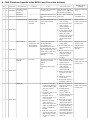
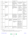
4. FAQ (Problems Specific to the MP510 and Corrective Actions)
Part 3: APPENDIX
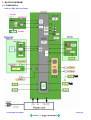
1. BLOCK DIAGRAM
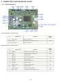
2. CONNECTOR LOCATION AND PIN LAYOUT
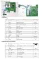
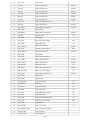
2-1. Logic Board Ass'y
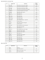
2-2. Card Slot Board
2-3. Operation Panel Board
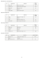
2-4. Carriage Board
3. PIXMA MP510 SPECIFICATIONS
1. MAINTENANCE
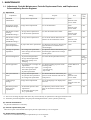
1-1. Adjustment, Periodic Maintenance, Periodic Replacement Parts, and Replacement
Consumables by Service Engineer
(1) Adjustment
Adjustment
Timing
Purpose
Tool
Approx.
time
EEPROM
initialization
At logic board replacement
To initialize settings.
None.
Perform in the
service mode.
1 min.
Destination settings
(EEPROM settings)
At logic board replacement
To set the destination.
None.
Perform in the
service mode.
1 min.
Ink absorber counter
resetting
(EEPROM settings)
- At logic board replacement
- At ink absorber replacement
To reset the ink absorber counter.
None.
Perform in the
service mode.
1 min.
Ink absorber counter
value setting
- At logic board replacement
To set the ink amount data in the ink
absorber to the ink absorber counter.
None.
Perform in the
service mode.
1 min.
Paper feed motor
position adjustment*1
At paper feed motor replacement
To adjust the belt tension. (Position the
paper feed motor so that the belt is
stretched tight.)
None.
5 min.
Carriage rail position
adjustment
- At carriage unit replacement
- After carriage rail removal and
re-assembly
To adjust the distance between the print
head and paper (between the carriage
and the platen).
None.
5 min.
Print head alignment
- At print head replacement
- At logic board replacement
- When print quality is not
satisfying
To secure the dot placement accuracy.
None.
3 min.
(manual,
auto*2)
Grease application
- At carriage unit or carriage rail
replacement
- At LF earth spring or paper
feed roller replacement
- At platen replacement
To maintain sliding properties of the
following items:
- Carriage unit
- LF earth spring
- Eject roller
FLOIL KG-107A
1 min.
Ink system function
check
- At logic board replacement
- At spur base unit replacement
- At carriage unit replacement
To maintain detection functionality for
presence of the ink tanks and each ink
tank position.
None.
Perform in the
service mode.
1 min.
LCD language
settings
At logic board replacement
To set the language to be displayed on
the LCD.
None.
Perform in the user
mode.
1 min.
Document pressure
sheet position
adjustment
- At document pressure sheet
replacement
- At document pressure plate
ass'y replacement
To adjust the pressure sheet to fit in
place to the reference mark in the left
back.
None.
1 min.
(EEPROM settings)
IF-20
*1: The screws securing the paper feed motor may be loosened only at replacement of the paper feed motor unit.
*2: Automatic print head alignment using the print head alignment sheet (via the operation panel only).
(2) Periodic maintenance
No periodic maintenance is necessary.
(3) Periodic replacement parts
There are no parts in this machine that require periodic replacement by a service engineer.
(4) Replacement consumables
There are no consumables that require replacement by a service engineer.
1-1
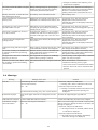
1-2. Customer Maintenance
Adjustment
Print head
alignment
Timing
Purpose
At print head replacement.
Tool
Approx.
time
To ensure accurate dot placement.
- Machine buttons
- Computer (MP driver)
3 min.
(manual,
auto*)
Print head cleaning When print quality is not satisfying.
To improve nozzle conditions.
- Machine buttons
- Computer (MP driver)
1 min.
Print head deep
cleaning
When print quality is not satisfying,
and not improved by print head
cleaning.
To improve nozzle conditions.
- Machine buttons
- Computer (MP driver)
2 min.
Ink tank
replacement
When an ink tank becomes empty.
("No ink error" displayed on the
monitor or on the machine LCD, or
short flashing of an ink tank LED)
To replace the empty ink tank.
None.
1 min.
ASF paper feed
roller cleaning
When paper does not feed properly, or To clean the paper feed rollers.
when the print side of the paper is
smeared
Machine buttons
2 min.
Front feeder paper When paper does not feed properly, or To clean the paper feed rollers.
feed roller cleaning when the back side of the paper is
smeared
None.
1 min.
Manually clean the rollers
with a cotton swab.
Bottom plate
cleaning
When the back side of the paper is
smeared.
To clean the platen ribs.
- Machine buttons
- Computer (MP driver)
1 min.
Scanning area
cleaning
When the following are dirty:
To clean the applicable items.
Soft, dry, and clean lintfree cloth.
1 min.
- Platen glass
- Document pressure sheet
* Automatic print head alignment using the print head alignment sheet (via the operation panel only).
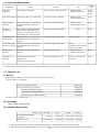
1-3. Product Life
(1) Machine
Specified print volume (I) or the years of use (II), whichever comes first.
(I) Print volume: 12,000 pages
Black 1,500 character pattern
5,500 pages
Color 7.5% duty per color pattern
3,600 pages
A4, photo, borderless printing
200 pages
4 x 6, photo, borderless printing
2,200 pages
500 pages
Postcard, photo, borderless printing
(II) Years of use: 5 years of use
(2) Print head
Print volume: 40,000 pages
(3) Ink tank (target value)
Average yield
Color document (ISO/IEC
FCD24712)*1
Photo (4" x 6")*2
PGI-5BK
CLI-8C
CLI-8M
CLI-8Y
510 pages
880 pages
680 pages
690 pages
(3,645 pages)
426 pages
280 pages
291 pages
*1: Declared yield value in accordance with ISO/IEC FCD24711. Values obtained by continuous printing.
*2: When printing Canon standard patterns on 4" x 6" Photo Paper Plus Glossy continuously with the default settings of Photo
1-2
Paper Plus Glossy using Windows XP printer driver in borderless printing mode and Windows XP Photo Printing Wizard. Declared
yield value determined based on Canon standard method referring to ISO/IEC FCD24712.
Note: Ink yield may vary depending on texts/photos printed, applications software used, print mode and type of paper used.
1-4. Special Tools
Name
Tool No.
Application
FLOIL KG-107A
QY9-0057-000
To be applied to the sliding portions of the
carriage rail and main chassis.
ELECTRICITY
GREASE IF-20
CK-8006-000
To be applied to the sliding portions of the
LF earth spring.
Remarks
In common with the
S520.
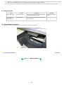
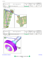
1-5. Serial Number Location
On the spur base unit (visible at the front center when the scanning unit is opened).
To the table of contents
To the top
<Part 1: 1. MAINTENANCE>
1-3
2. LIST OF ERROR DISPLAY / INDICATION
Errors and warnings are displayed by the following ways:
1) Operator call errors are indicated by the Alarm LED lit in orange, and the error and its solution are displayed on the LCD in text and by
icon.
2) Messages during printing from a computer are displayed on the MP driver Status Monitor.
3) Error codes are printed in the "operator call/service call error record" area in EEPROM information print.
Buttons valid when an operator call error occurs:
1) ON/OFF button: To turn the machine off and on again.
2) OK button: To clear and recover from an error. In some operator call errors, the error will automatically be cleared when the cause of
the error is eliminated, and pressing the OK button may not be necessary.
3) Stop/Reset button: To cancel the job at error occurrence, and to clear the error.
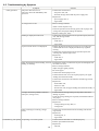
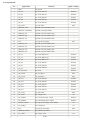
2-1. Operator Call Errors (by Alarm LED Lit in Orange)
Error
Error code
Message on the LCD
Solution
No paper in the ASF.
[1000]
Auto sheet feeder.
Confirm that the ASF is selected as the paper
There is no paper. Load paper and press [OK]. source. Set the paper in the ASF, and press the
OK button.
No paper in the front
feeder.
[1003]
Front feeder.
Paper jam.
[1300]
Paper jam in the rear
guide.
[1303]
The paper is jammed. Clear the paper and press Remove the jammed paper, and press the OK
button.
[OK].
No ink.
[1600]
The following ink may have run out. Replacing Replace the empty ink tank(s), and close the
cover.
the ink tank is recommended. (U041)
Pressing the OK button will clear the error
without ink tank replacement, however, ink
may run out during printing.
Ink tank not installed.
[1660]
The following ink tank cannot be recognized.
(Applicable ink tank icon) (U043)
Install the applicable ink tank(s) properly, and
confirm that the LED's of all the ink tanks light
red.
The print head is not
installed, or it is not
properly installed.
[1401]
Print head is not installed. Install the print
head.
Install the print head properly.
Print head temperature
sensor error
[1403]
The type of print head is incorrect. Install the
correct print head.
Faulty EEPROM data of
the print head
[1405 / 1682]
Re-set the print head. If the error is not cleared,
the print head may be defective. Replace the
print head.
Multiple ink tanks of the
same color installed.
[1681]
More than one ink tank of the following color
is installed. (U071)
Replace the wrong ink tank(s) with the correct
one(s).
Ink tank in a wrong
position.
[1680]
Some ink tanks are not installed in place.
(U072)
Install the ink tank(s) in the correct position.
Warning: The ink
absorber becomes almost
full.
[1700 / 1701 / Contact the support center or service center for Replace the ink absorber, and reset its counter.
1710 / 1711] ink absorber replacement. Press [OK] to
[See 3-3. Adjustment / Settings, (6) Service
continue printing.
mode.]
Pressing the OK button will exit the error, and
enable printing without replacing the ink
absorber. However, when the ink absorber
becomes full, no further printing can be
performed unless the applicable ink absorber is
replaced.
The connected digital
camera or digital video
camera does not support
Camera Direct Printing.
[2001]
Incompatible device detected. Remove the
device.
Remove the cable between the camera and the
machine.
Failed in automatic print
head alignment.
[2500]
Failed to scan head alignment sheet. Check
orientation and position, and make sure platen
and sheet are clean. <See manual>
1-4
Press the OK button to clear the error, and
perform automatic print head alignment again
after confirming the following:
Confirm that the front feeder is selected as the
There is no paper. Load paper and press [OK]. paper source. Set the paper in the front feeder,
and press the OK button.
- Fill in all the circles on the print head
alignment sheet.
- Place the sheet in the correct orientation and
position.
The remaining ink amount [1683]
unknown.
(Applicable ink tank icon)
The remaining level of the following ink
cannot be correctly detected. Replace the ink
tank. (U130)
An ink tank which has once been empty is
installed. Replace the applicable ink tank with
a new one.
Printing with a once-empty ink tank can
damage the printer.
To continue printing without replacing the ink
tank(s), press the OK button for 5 sec. or
longer to disable the function to detect the
remaining ink amount. After the operation, it is
recorded in the printer EEPROM that the
function to detect the remaining ink amount
was disabled.
Ink tank not recognized.
The following ink tank cannot be recognized.
(U140)
A non-supported ink tank is installed (the ink
tank LED is turned off). Install the supported
ink tanks.
[1684]
(Applicable ink tank icon)
Ink tank not recognized.
[1410 to
1419]
The following ink tank cannot be recognized.
(U150)
(Applicable ink tank icon)
Scanning unit (printer
cover) open.
[1200]
Cover is open. Close cover.
A hardware error occurred in an ink tank (the
ink tank LED is turned off). Replace the ink
tank(s).
Close the scanning unit (printer cover).
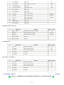
2-2. Service Call Errors (by Cyclic Blinking in Orange (Alarm LED) and Green (Power LED), or
Both LEDs Lit)
Service call errors are indicated by the number of cycles the Alarm LED and Power LED blink, and the corresponding error code is
displayed on the LCD.
Cycles of blinking
in orange (Alarm
LED) and green
(Power LED)
Error
Error
code
Conditions
2 times
Carriage error [5100] An error occurred in the carriage encoder signal.
3 times
Line feed error [6000] An error occurred in the LF encoder signal.
4 times
Purge cam
sensor error
[5C00] An error occurred in the purge unit.
5 times
ASF (cam)
sensor error
[5700] This error takes place when feeding paper from the
ASF after an error occurred in the ASF cam sensor.
6 times
Internal
temperature
error
Ink absorber
full
[5400] The internal temperature is not proper.
7 times
Solution
(Replacement of listed parts, which
are likely to be faulty)
- Carriage unit (QM2-3753)
- Timing slit film (QC1-9542)
- Logic board (QM2-3827)
- Carriage motor (QM2-3872)
- Timing sensor unit (QM2-3878)
- Timing slit disk film (QC1-9597)
- Feed roller (QL2-1407)
- Logic board (QM2-3827)
- Paper feed motor (QM2-3873)
- Purge unit (QM2-3754)
- Logic board (QM2-3827)
- Sheet feed unit (QM2-3762)
- ASF_PE sensor board (QM2-3877)
- Logic board (QM2-3827)
- Logic board (QM2-3827)
- Carriage unit (QM2-3753)
[5B00, The ink absorber is full.
5B10,
5B01,
5B11] Error codes:
Overseas:
5B00: Main ink absorber
5B10: Borderless-print ink absorber
Japan:
5B01: Main ink absorber
1-5
- Ink absorber kit (QY5-0178)
8 times
9 times
10 times
Print head
temperature
rise error
EEPROM
error
VH monitor
error
5B11: Borderless-print ink absorber
[5200] The print head temperature exceeded the specified
value.
- Print head (QY6-0070)
- Logic board (QM2-3827)
[6800] A problem occurred in writing to the EEPROM.
- Logic board (QM2-3827)
[B200] The internal temperature exceeded the specified
value.
- Print head (QY6-0070)
- Carriage unit (QM2-3753)
- Logic board (QM2-3827)
- Sheet feed unit (QM2-3762)
- Logic board (QM2-3827)
- Purge unit (QM2-3754)
- Logic board (QM2-3827)
12 times
PG position
error
[5C10] An error occurred in the PG motor during purging
operation.
15 times
USB Host
VBUS
overcurrent
Ink tank
position sensor
error
Other
hardware error
Scanner home
position error
[9000] The USB Host VBUS is overloaded.
19 times
20 times
22 times
Alarm and Power
LEDs lit
ROM error,
RAM error
[6502] None of the ink tank position is detected.
- Spur base unit (QM2-3750)
- Logic board (QM2-3827)
[6500] The PCI bus error is detected by the ASIC.
- Logic board (QM2-3827)
[5010] The scanner unit cannot detect the home position, or
the scanner unit warming-up is not performed
properly at power-on.
On the LCD, "Scanner is not operating correctly." is
displayed.
A flash ROM or RAM checksum error occurred at
hard-power-on.
- Scanner unit (QM2-3775)
- Logic board (QM2-3827)
Note: Before replacement of the logic board ass'y, check the ink absorber counter value (by service test print or EEPROM information
print). If the counter value is 7% or more, also replace the ink absorber kit (QY5-0178) when replacing the logic board ass'y, or
register the current ink absorber counter value to the replaced new logic board instead. [See 3-3. Adjustment / Settings, (9)
Service mode, for details.]
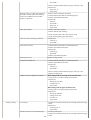
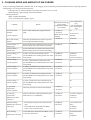
2-3. Other Error Messages
Message on the LCD
The selected paper cannot be fed from
front feeder. Change the paper source.
Borderless print is not available for
paper from the front feeder. Change the
paper source and press [OK].
Cannot specify the followings together.
Change one of the settings.
Cause
The paper type being used is not supported for
paper feeding from the front feeder.
Borderless print is attempted when the front
feeder is selected as the paper source.
Solution
Change the paper source to the ASF.
Press <>.
(<>: Color button icon)
Press <>.
(<>: Black button icon)
There are no photos in memory card.
The Black button was pressed, but it is invalid.
A temporary error. Press the Color button to
continue the operation.
The Color button was pressed, but it is invalid.
A temporary error. Press the Black button to
continue the operation.
Supported image files are not in the memory
card.
A temporary error.
- Confirm that supported image files are in the
memory card.
- Images with double-byte characters used in
the file name (or folder name) may not be
recognized. Change the file (or folder) name
so that it contains only single-byte
alphanumeric characters.
Change the paper source to the ASF.
Settings made conflict each other.
The error message is displayed for a while, then
the LCD automatically returns to the display
before the error occurrence.
Device memory is full. Cannot continue The memory is not sufficient to do the print job. Reduce the amount of data to be printed, or
process. Reduce the number of photos to
print from a computer.
print.
Failed to scan. Either document cannot The machine failed in scanning the document
Press the OK button to clear the error.
be scanned or is not placed on the platen for Fit-to-page copy, or photos or films were
glass.
not recognized in pre-scanning.
1-6
- If images are edited on the computer, print
them from the computer.
The value exceeds the number of copies During selecting images or specifying the
you can print.
number of copies, the total print quantity
exceeds the prescribed value of 999.
A temporary error. After the error message is
displayed for a while, the last operation before
the error is cancelled, and the total print
quantity returns to the value before the error.
Memory card is not set. Insert the card
after checking the direction.
DPOF information is not saved in the
memory card.
Set a memory card.
No memory card is inserted in the slot.
DPOF print was selected in the menu, but no
DPOF files are contained in the memory card.
A temporary error. The error message is
displayed for a while, then the LCD
automatically returns to the display before the
error occurrence.
The number of copies to print is not set. Multi-photo print was attempted without
A temporary error. The error message is
Input the number of copies.
specifying the print quantity (with the print
displayed for a while, then disappears. Specify
quantity left "0" (zero)).
the print quantity.
This layout is available only for A4 or
In Layout print, "Mixed 1, 2, or 3" which is
A temporary error. The error message is
8.5"x11"(215x279).
available only with A4 or LTR size paper is
displayed for a while, then the LCD
selected, but the paper size is not set to A4 or
automatically returns to the display before the
LTR.
error occurrence.
Settings cannot be changed when
With Sticker print selected, the Settings button A temporary error. The error message is
printing stickers.
was pressed.
displayed for a while, then the LCD
automatically returns to the display before the
error occurrence.
Change the setting after removing the
With a memory card inserted in the slot, change A temporary error. Remove the memory card,
card.
of the Read/Write attribute was attempted.
then change the Read/Write attribute.
The card is currently write-enabled. Set With the memory card set to the Read/write
A temporary error. Remove the memory card,
to read-only mode before performing
mode, Card Direct printing operation was
change the memory card setting to Read-only,
operation.
attempted from the menu.
then perform Card Direct printing.
The paper size is not correct. Check the Non-supported size of paper for PictBridge
Cancel printing on the digital camera. Check the
page size you have set.
Camera Direct printing is selected.
paper size, then print again.
Failed to scan Photo Index Sheet. Check The machine failed in scanning the Photo Index Press the OK button to clear the error.
the orientation, position and marking.
Sheet.
Confirm the following, then try again:
<See manual>
- Fill in all the circles on the Photo Index Sheet.
- Place the sheet in the correct orientation and
position.
2-4. Warnings
Warning
Low ink
Message on the LCD
The following ink is low. Continue?
(Icon of each ink tank)
Yes No
Solution
- Select Yes, and press the OK button.
=> Printing starts, and it is indicated on the LCD.
- Select No, and press the OK button.
=> Printing is cancelled, and the LCD returns to the
display immediately before printing was
In Camera Direct Printing, only "Yes" can be selected.
attempted.
Restrictions on paper
The current paper cannot be set. Change the size and
type.
Re-select the supported paper type and size.
USB cable not connected
Connect USB cable and turn on the PC.
Connect the USB cable, then turn on the computer.
Cancellation of image
select information
Reset the selected photo information?
Yes No
When one or more images are selected in Layout print,
and if a user tries to display the menu or sub-menu, the
message is displayed.
- Select Yes, and press the OK button.
=> The image selection is cancelled, and the menu
or sub-menu is displayed.
- Select No, and press the OK button.
=> The LCD returns to the display immediately
before the message was displayed.
1-7
2-5. Troubleshooting by Symptom
Symptom
Faulty operation
Solution
The power does not turn on.
The power turns off immediately after
power-on.
- Confirm the connection of
- the power cord, and
- between the logic board and the power supply unit.
- Replace the
- power supply unit, or
- logic board.
A strange noise occurs.
- Remove foreign material.
- Attach a removed part if any.
- Check the operation of the moving parts (such as purge unit,
carriage unit, and paper feeding mechanism)
- Replace a faulty part, if any.
Nothing is displayed on the LCD.
- Confirm the connection between the operation panel, the LCD
unit, and the logic board.
- Replace the
- LCD unit, or
- logic board.
A portion of the LCD is not displayed.
- Perform the button and LCD test in the service mode, and
confirm that the LCD is displayed without any segments
missing.
- Confirm the connection between the operation panel, the
scanning unit, and the logic board.
- Replace the
- LCD unit, or
- logic board.
Paper feed problems (multi-feeding, skewed - Examine the inside to confirm that no parts are damaged, and
feeding, no feeding).
the rollers are clean.
- Remove foreign material.
- Adjust the paper guide properly.
- Re-set the paper.
- Confirm the selected paper source.
- Confirm that the rear cover fits in place properly (for paper
feeding from the front feeder).
- Confirm the connection of each harness and the logic board.
- Replace the
- sheet feeder unit,
- ASF cover unit,
- bottom case unit (for paper feeding from the front feeder), or
- logic board.
Carriage movement problems (contact to
other parts, strange noise).
- Confirm that the carriage timing slit strip film is free from
damage or grease.
- Clean the carriage timing slit strip film (with ethanol and lintfree paper).
- Remove foreign material.
- Replace the
- carriage timing slit strip film, or
- carriage unit.
Faulty scanning (no scanning, strange
noise).
- Confirm the connection between the scanning unit and the
logic board.
- Replace the
- scanning unit, or
- logic board.
Unsatisfactory print quality No printing, or no color ejected.
1-8
- Confirm that the ink tanks are installed properly.
- Perform print head maintenance.
- Replace the
- ink tank,
- print head*1.
- Remove foreign material from the purge unit caps, if any.
- Replace the
- purge unit, or
- logic board.
Printing is faint, or white lines appear on
printouts even after print head cleaning.
Line(s) not included in the print data
appears on printouts.
- Remove and re-install the print head.
- Confirm that the ink tanks are installed properly.
- Perform print head maintenance.
- Replace the
- ink tank,
- print head*1,
- purge unit, or
- logic board.
Paper gets smeared.
- Feed several sheets of paper.
- Perform bottom plate cleaning.
- Clean the paper path with cotton swab or cloth.
- Clean the front feeder paper feed rollers.
A part of a line is missing on printouts.
- Replace the
- ink tank, or
- print head*1.
Color hue is incorrect.
- Confirm that the ink tanks are installed properly.
- Perform print head maintenance.
- Replace the
- ink tank, or
- print head*1.
- Perform print head alignment.
Printing is incorrect.
Replace the logic board.
No ejection of black ink.
- Confirm that the ink tanks are installed properly.
- Perform print head maintenance.
- Replace the
- ink tank, or
- print head*1.
- Remove foreign material from the purge unit caps, if any.
- Replace the purge unit.
Faulty scanning
Graphic or text is enlarged on printouts.
When enlarged in the carriage movement direction:
- Clean grease or oil off the timing slit strip film.
- Replace the
- timing slit strip film,
- carriage unit, or
- logic board.
When enlarged in the paper feed direction:
- Clean grease or oil off the timing slit disk film.
- Replace the
- timing slit disk film,
- timing sensor unit,
- LF roller, or
- logic board.
No scanning.
- Confirm the connection between the scanning unit and the logic
board.
- Replace the
- scanning unit, or
- logic board.
Streaks or smears on the scanned image.
- Clean the platen glass.
- Confirm the connection between the scanning unit and the logic
board.
1-9
- Replace the
- scanning unit,
- logic board, or
- document pressure sheet.
*1: Replace the print head only after the print head deep cleaning is performed 2 times, and when the problem persists.
To the table of contents
To the top
<Part 1: 2. LIST OF ERROR DISPLAY / INDICATION>
1-10
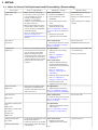
3. REPAIR
3-1. Notes on Service Part Replacement (and Disassembling / Reassembling)
Service part
Logic board ass'y
QM2-3827
Notes on replacement*1
- Before removal of the logic
board ass'y, remove the power
cord, and allow for approx. 1
minute (for discharge of
capacitor's accumulated
charges), to prevent damages to
the logic board ass'y.
- Before replacement, check the
ink absorber counter value (by
service test print or EEPROM
information print).
[See 3-4. Verification Items, (1)
Service test print, or (2)
EEPROM information print, for
details.]
Absorber kit
QY5-0178
Carriage unit
QM2-3753
Adjustment / settings
After replacement:
1. Initialize the EEPROM.
2. Set the destination in the
EEPROM.
3. Set the ink absorber counter
value.
4. Set the language to be
displayed on the LCD.
[See 3-3. Adjustment / Settings,
(9) Service mode, for details of 1
to 4]
5. Perform the print head
alignment in the user mode.
Operation check
- EEPROM information print
- Service test print
- Printing via USB connection
- Copy
- Direct printing from a digital
camera
After replacement:
- Service test print
1. Reset the ink absorber counter. - EEPROM information print
[See 3.3. Adjustment / Settings,
(9) Service mode.]
- The screws securing the carriage
rail are allowed to be loosened
only at carriage replacement.
Before removing the screws,
mark the positions of the screws
on the carriage rail so that they
will be returned to their original
positions after the carriage is
replaced.
- Service test print (Confirm ink
At replacement:
system function.)
1. Apply grease to the sliding
portions.
- Printing on thick paper
[See 3-3. Adjustment /
Settings, (5) Grease
application.]
After replacement:
1. Adjust the distance between
the print head and the paper
(between the carriage rail and
the platen).
[See 3.3. Adjustment /
Settings, (2) Carriage rail
adjustment.]
2. Check the ink system function.
[See 3.3. Adjustment /
Settings, (9) Service mode.]
3. Perform the print head
alignment in the user mode.
Paper feed motor
QM2-3873
Spur base unit
QM2-3750
Document pressure plate
ass'y
QM2-3756,
Document pressure sheet
QC1-9514,
Scanner unit
QM2-3775
Timing slit strip film
QC1-9542
Timing slit disk film
- The screws securing the paper
feed motor are allowed to be
loosened. (DO NOT loosen any
other red screws.)
At replacement:
1. Adjust the paper feed motor.
[See 3-3. Adjustment / Settings,
(1) Paper feed motor adjustment.]
- Service test print
After replacement:
1. Check the ink system function.
[See 3.3. Adjustment / Settings,
(9) Service mode.]
At replacement:
1. Adjust the document pressure
sheet position.
[See 3.3. Adjustment / Settings,
(2) Carriage rail adjustment.]
- Upon contact with the film, wipe After replacement:
the film with ethanol.
1. Perform the print head
- Confirm no grease is on the film.
alignment in the user mode.
(Wipe off any grease thoroughly
with ethanol.)
1-11
- Service test print
QC1-9597
- Do not bend the film.
Print head
QY6-0070
After replacement:
1. Perform the print head
alignment in the user mode.
- Service test print
*1: General notes:
- Make sure that the flexible cables and wires in the harness are in the proper position and connected correctly.
See 3-2. Special Notes on Repair Servicing, or Parts Catalog, for details.
- Do not drop the ferrite core, which may cause damage.
- Protect electrical parts from damage due to static electricity.
- Before removing a unit, after removing the power cord, allow the machine to sit for approx. 1 minute (for capacitor discharging
to protect the logic board ass'y from damages).
- Do not touch the timing slit strip film and timing slit disk film. No grease or abrasion is allowed.
- Protect the units from soiled with ink.
- Protect the housing from scratches.
- Exercise caution with the red screws, as follows:
i. The screws of the paper feed motor may be loosened only at replacement of the paper feed motor unit (DO NOT loosen
them in other cases).
ii. The screws securing the carriage rail may be loosened only at replacement of the carriage unit. After carriage unit
replacement, print on thick paper to confirm that the distance between the print head and paper (between the carriage rail
and the platen) is correct, and that the print head does not contact the paper during printing. If the print head contacts the
paper, adjust the carriage rail position, while referring to [3-3. Adjustment / Settings, (2) Carriage rail adjustment.]
To the table of contents
To the top
<Part 1: 3. REPAIR; 3-1. Notes on Service Part Replacement>
1-12
3-2. Special Notes on Repair Servicing
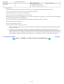
(1) Side cover L2 and front cover L removal
i) Remove 1 screw from the front cover L.
ii) While pushing the lock pin, slide the front cover L to the right to remove it.
iii) Release the hook of the right front of the side cover L2, while pulling the cover downward.
iv) Slide the side cover L2 toward the machine front, and remove it.
1-13
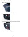
(2) Side cover R2 and front cover R removal
i) Release the hook of the side cover R2.
ii) Slide the side cover R2 toward the machine front, and remove it.
iii) Remove 1 screw from the front cover R.
1-14
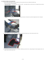
iv) Remove 2 hooks (No. 1 in the photo below). While pressing the lock pin (No. 2 in the photo below), slide the front cover R
toward the machine front, and remove it.
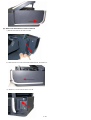
(3) Main case removal
i) Remove the front covers L / R, side covers R1 / R2 / L1 / L2, and scanner unit.
ii) Release 2 bosses, and remove the ASF cover unit.
iii) Remove 4 screws and the main case.
1-15
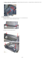
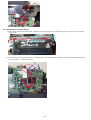
(4) Scanner flexible cable attachment
i) On the double-sided adhesive tape in the right back of the top of the main case, attach the flexible cable.
The cores should be located as follows:
- Place the core (No. 2 in the photo below) so that the rib (No. 1 in the photo below) is between the core edges (between the blue
lines in the photo).
- Align another core (indicated by the red arrow in the photo below) to the main case protrusion edges (blue lines in the photo
below).
ii) Attach the FFC sheet, with its right back portion passing under the flexible cable, as shown below (blue circle).
iii) Connect the flexible cable connectors at 3 locations (indicated by the red arrows), while passing the cable through the main case
frame as shown below (blue circle).
1-16
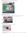
(5) Timing sensor unit cable wiring
i) Fit the cables in the flexible cable guide, and attach them to the main chassis with filament tape at 2 locations, as shown below
(blue circles).
ii) Pass the timing sensor unit cables (No. 2 in the photo below) through under the cable between the main board and the ASF_PE
sensor board (No. 1 in the photo below).
1-17
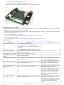
(6) Flexible cable between the card board ass'y and the logic board ass'y
i) Attach the core to the cable.
ii) Fix the core with filament tape, as shown in the photo below.
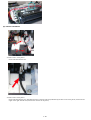
(7) Carriage unit flexible cable wiring
i) Attach the core to a set of carriage unit cables (3 cables).
ii) Fit the cables in the FCC guide so that the core comes to the location indicated by the red arrow in the photo below.
iii) Attach the cables to the main chassis with filament tape, as shown in the photo below (blue circle).
(8) Power supply unit cable wiring
i) Pass the cables through the core 3 times so that they loop around the core.
ii) Fit the cables in the FCC guide.
iii) Using filament tape, attach the cables (together with the timing sensor ass'y cables) to the main chassis , as shown in the photo
below (blue circle).
1-18
(9) Ink tube installation
<About Circle 1 in the photo>
Fit the tube between the ribs.
<About Circle 2 in the photo>
Fit the tube between the ribs, and adjust the tube so that the tube end (indicated by the blue circle in the photo) is between the
edges of the right and left ribs (between the red lines in the photo).
1-19
(10) Platen link assembly
Assemble the platen link so that the paper thickness lever boss is in the platen link hole, as shown in the photo.
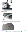
(11) Emblem removal
Push the point indicated by the arrow in the photo to remove from the double-sided adhesive tape.
To the table of contents
To the top
<Part 1: 3. REPAIR; 3-2. Special Notes on Repair Servicing>
1-20
3-3. Adjustment / Settings
(1) Paper feed motor adjustment
Perform the following adjustments when the paper feed motor unit is replaced:
1) When attaching the motor, fasten the screws so that the belt is properly stretched (in the direction indicated by the blue arrow in the
figure below).
2) After replacement, be sure to perform the service test print, and confirm that no strange noise or faulty print operation (due to
dislocation of the belt or gear, or out-of-phase motor, etc.) occurs.
Note: The red screws securing the paper feed motor may be loosened only at replacement of the paper feed motor unit. DO NOT
loosen them in other cases.
(2) Carriage rail adjustment
Perform the following adjustments when attaching the carriage rail:
1) Before loosening the screws, mark the following positions on the rail:
- Left side: Mark the boss position.
- Right side: Mark the hole position.
2) In attaching the carriage rail, make sure that the left boss and right hole fit to the marks made in step 1) respectively, then fasten the
screws.
3) Be sure to perform the confirmation test detailed below; confirm that the print quality is proper and the print head is not contacting
the paper.
<Confirmation test>
Using Photo Paper Pro, and with the paper thickness lever set to the left position (normal position), print an image and confirm that the
print quality is proper, and the print head is free from contacting the paper.
If the print quality is not proper, or the print head contacts the paper, adjust the head-to-paper distance in the following procedures:
1-21
<How to adjust the head-to-paper distance>
i) Mark the current position of the left boss and the right hole. (See the step 1 of the carriage rail adjustment above.)
ii) Loosen the hexagon-head screws, and adjust the head-to-paper distance.
- To prevent the print head from contacting the paper: Raise the carriage rail from the current position.
- To improve the print quality: Lower the carriage rail from the current position.
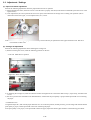
(3) Document pressure sheet adjustment
Adjust the document pressure sheet as follows:
1) Peel off the cover sheet from the double-sided adhesive tape of the document pressure sheet, and position one of the corners of the
sheet at the scanning reference point (back left) on the platen glass.
2) Slowly close the document pressure plate ass'y. The document pressure sheet will attach to the document pressure plate ass'y.
3) Open the document cover to confirm the following:
- No extension of the sponge edges over the mold part of the document cover.
- No gap between the platen glass reference edges and the corresponding sponge edges.
(4) Front feeder paper feed roller cleaning
1) Press the ON/OFF button to turn off the machine.
2) Set 5 sheets or more of A4 or letter size plain paper in the front feeder.
3) Push the rear cover tab to the right and pull out the rear cover.
Caution: Be cautious not to touch the collars (indicated by the red circles in the photo below) of the front feeder guide. They can
easily be removed when contacted.
1-22
4) While rotating the paper feed roller toward you using your finger, wipe off smears with a cotton swab. If a smear or stain is not
removed easily, moisten the swab and clean the roller.
5) When cleaning is completed, remove the paper from the front feeder, and re-set it.
6) Attach the rear cover.
Caution: Make sure the rear cover fits in place. Improper attachment of the cover will cause paper jams.
(5) Grease application
z
Machine unit
No
1
2
3
Part name
Chassis ass'y
Carriage rail
Carriage rail
4 Carriage rail
Where to apply grease/ oil
Number of
Grease/ oil
locations to
amount
apply grease/
(mg)
oil
Floil KG107A 240 +/- 20
1
Grease/ oil
name
Behind the top front of the chassis where the carriage
unit slides
Top surface of the carriage rail where the carriage unit Floil KG107A
(2)
slides
Front surface of the carriage rail where the carriage unit Floil KG107A
(3)
slides
(4) Back of the carriage rail where the carriage unit slides
Floil KG107A
(1)
1-23
475 +/- 25
1
240 +/- 20
1
250 +/- 50
1
z
Platen
No
Part name
5 Platen
Grease/ oil
name
Where to apply grease/ oil
(5) Eject roller sliding portion
Floil KG107A
Number of
locations to
apply grease/
oil
1/2
3
Grease/ oil
Number of
amount
drops*
(mg)
4.5 to 9
*1 drop = 9 to 18 mg
z
LF roller
No
Part name
6 LF roller
Grease/ oil
name
Where to apply grease/ oil
(6) LF earth spring sliding portion
IF-20
Number of
locations to
apply grease/
oil
1/2
1
Grease/ oil
Number of
amount
drops*
(mg)
9 to 18
*1 drop = 9 to 18 mg
To the table of contents
To the top
<Part 1: 3. REPAIR, 3-3 (1) to (5)>
1-24
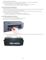
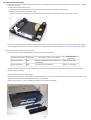
(6) Ink absorber replacement
1) At the time of an error indicating that the ink absorber is full, replace either the main or the borderless-print ink absorber according
to the error message.
- When the main ink absorber is full:
Replace the absorber indicated by the blue frame in the photo below (component of QY5-0178).
- When the borderless-print ink absorber is full:
Replace 2 absorbers in the red circle in the photo below and the platen ink absorber (components of QY5-0178).
The main ink absorber and the borderless-print ink absorber have separate counters respectively. After ink absorber replacement,
reset the applicable ink absorber counter according to the replaced ink absorber. For details, see (7) Ink absorber counter setting.
2) Partial replacement of the main ink absorber
For the main ink absorber, the following replacement methods are available:
Replacement method
Difficulties
Ink absorber volume to be replaced
Print yield after
replacement
Partial replacement
Low
Approx. a half portion of the entire main
ink absorber
Approx. 4,800 pages
Whole replacement
High
The entire main ink absorber
Approx. 12,000 pages
After ink absorber replacement, set the ink absorber counter value according to the replacement method. See (7) Ink absorber
counter setting, for details.
<How to perform the partial replacement>
Remove the rear cover (No. 1 in the photo) and the ink absorber cover (No. 2 in the photo) from the rear side of the machine, and
replace a half portion of the main ink absorber (No. 3 in the photo).
(Time required: Approx. 4 min. including the operation check after replacement)
1-25
<The portion replaced in the partial replacement>
- Entire main ink absorber: Indicated by the green lines
- The portion to be replaced in partial replacement: Indicated by the blue lines
(7) Ink absorber counter setting
Before replacement of the logic board ass'y, check the ink absorber counter value. After the logic board ass'y is replaced, set the ink
absorber counter value to the replaced logic board ass'y.
In addition, according to the counter value, replace the ink absorber (ink absorber kit). When the ink absorber is replaced, reset the
applicable ink absorber counter (to "0%").
How to check the ink absorber counter value:
See 3-4. Verification Items, (1) Service test print, or (2) EEPROM information print.
How to set the ink absorber counter:
See 3-3. Adjustment / Settings, (9) Service mode, "Ink absorber counter setting procedures."
(8) User mode
Function
Procedures
Print head manual cleaning
- Cleaning both Black and Color:
Perform via the machine operation panel.
- Cleaning Black or Color separately, or both Black
and Color:
Perform from the MP driver Maintenance tab.
Print head deep cleaning
Perform via the machine operation panel, or from the
MP driver Maintenance tab.
Remarks
ASF paper feed roller cleaning Perform via the machine operation panel.
Front feeder paper feed roller
cleaning
Clean the rollers manually.
Nozzle check pattern printing
Perform via the machine operation panel, or from the
MP driver Maintenance tab.
Set a sheet of plain paper (A4 or Letter) in
the ASF or the front feeder which is
selected on the Paper Feed Switch button.
Manual print head alignment
Perform via the machine operation panel, or from the
MP driver Maintenance tab.
Set 2 sheets of plain paper (A4 or Letter)
in the ASF or the front feeder which is
selected on the Paper Feed Switch button.
Automatic print head
alignment
Perform via the machine operation panel.
Print head alignment using the first page
of Print Head Alignment Sheet.
Set a sheet of plain paper (A4 or Letter) in
the ASF or in the front feeder which is
selected by the Paper Feed Switch button.
If the automatic print head alignment is
not effective, perform the manual print
head alignment.
Bottom plate cleaning
Perform via the machine operation panel, or from the
MP driver Maintenance tab.
Cleaning of the platen ribs when the back
side of paper gets smeared.
Fold a sheet of plain paper (A4 or Letter)
in half crosswise, then unfold and set it in
the ASF with the folded ridge facing
down.
1-26
(9) Service mode
Function
Procedures
Remarks
Service test print
- Model name
- Destination
- ROM version
- USB serial number
- Ink absorber counter value
(ink amount in the ink
absorber)
- Ink system function check
result
See "Service mode operation procedures"
below.
Set a sheet of A4 or letter size paper.
For print sample, see 3-4. Verification Items, (1)
Service test print, <Service test print sample>.
EEPROM information print
- Model name
- Destination
- ROM version
- Ink absorber counter value
(ink amount in the ink
absorber)
- Print information
- Error information, etc.
See "Service mode operation procedures"
below.
Set a sheet of A4 or letter size paper.
EEPROM initialization
See "Service mode operation procedures"
below.
The following items are NOT initialized, and the
shipment arrival flag is not on:
- USB serial number
- Destination settings
- Ink absorber counter value (ink amount in the ink
absorber)
Ink absorber counter reset
See "Service mode operation procedures"
below.
Destination settings
See "Service mode operation procedures"
below.
Button and LCD test
See "Service mode operation procedures"
below.
Ink absorber counter setting
See "Service mode operation procedures"
below.
<Service mode operation procedures>
1) With the machine power turned off, while pressing the Stop/Reset button, press and hold the ON/OFF button. (DO NOT release the
buttons). The Power LED lights in green to indicate that a function is selectable.
2) While holding the ON/OFF button, release the Stop/Reset button. (DO NOT release the ON/OFF button.)
3) While holding the ON/OFF button, press the Stop/Reset button 2 times, and then release both the ON/OFF and Stop/Reset buttons.
(Each time the Stop/Reset button is pressed, the Alarm and Power LEDs light alternately, Alarm in orange and Power in green,
starting with Alarm LED.)
4) When the Power LED lights in green (and "CANON Idle" is displayed on the LCD), press the Stop/Reset button the specified
number of time(s) according to the function listed in the table below, then press the ON/OFF button. (Each time the Stop/Reset
button is pressed, the Alarm and Power LEDs light alternately, Alarm in orange and Power in green, starting with Alarm LED.)
Time(s)
LED indication
Function
Remarks
0 times
Green (Power)
Power off
When the print head is not installed, the carriage
returns and locks in the home position capped.
1 time
Orange (Alarm)
Service test print
See 3-4. Verification Items, (1) Service test print.
2 times
Green (Power)
EEPROM information print
See 3-4. Verification Items, (2) EEPROM information
print.
3 times
Orange (Alarm)
EEPROM initialization
4 times
Green (Power)
Ink absorber counter
resetting
5 times
Orange (Alarm)
Destination settings
1-27
See "Ink absorber counter resetting procedures" below.
Press the Stop/Reset button the specified number of
time(s) according to the destination.
See "Destination settings procedures" below.
6 times
Green (Power)
7 to 9 times
Orange at odd
numbers (Alarm)
Green at even
numbers (Power)
10 times
Green (Power)
Eject roller correction
11 times
Orange (Alarm)
Return to the menu selection
12 times
Green (Power)
Button and LCD test
13 times
Orange (Alarm)
Ink absorber counter setting See "Ink absorber counter setting procedures" below.
14 times or
more
Green (Power)
Return to the menu selection
Print head deep cleaning
Cleaning of both Black and Color
Return to the menu selection
Not used in servicing.
See "Button and LCD test procedures" below.
Note: - If the Stop/Reset button is pressed 14 or more times, the Alarm LED (orange) or Power LED (green) lights steadily without
any changes.
<Destination settings procedures>
In the destination settings mode, press the Stop/Reset button the specified number of time(s) according to the destination listed in the
table below, and press the ON/OFF button.
Time(s)
LED indication
Destination
0 times
Green (Power)
No change of the destination
1 time
Orange (Alarm)
Japan
2 times
Green (Power)
Korea
3 times
Orange (Alarm)
US
4 times
Green (Power)
Europe
5 times
Orange (Alarm)
Australia
6 times
Green (Power)
Asia
7 times
Orange (Alarm)
China
8 times
Green (Power)
Taiwan
9 times or more
Orange (Alarm)
Return to the menu selection
Note: Confirm the model name and destination in service test print or EEPROM information print.
<Ink absorber counter resetting procedures>
After replacement of the ink absorber, reset the applicable ink absorber counter.
1) Before replacement of the ink absorber, check the ink absorber counter value in EEPROM information print. See 3-4. Verification
Items, (2) EEPROM information print.
2) In the ink absorber counter resetting mode, press the Stop/Reset button the specified number of time(s) according to the replaced ink
absorber to set its counter to 0%, or 60% (for partial replacement).
Time(s)
Replaced ink absorber
Counter value
0 times
Main ink absorber
Reset to 0%
1 time
Borderless-print ink absorber
Reset to 0%
2 times
Both the main and borderless-print ink absorbers
Reset to 0%
3 times
A half portion of the main ink absorber (partial replacement) Set to 60%
1-28
<Ink absorber counter setting procedures>
Set the ink absorber counter data to a replaced new EEPROM after the logic board is replaced in servicing.
1) Before replacement of the logic board ass'y, check the ink absorber counter value in EEPROM information print. See 3-4.
Verification Items, (2) EEPROM information print.
2) In the ink absorber counter setting mode, press the Stop/Reset button the specified number of time(s) according to the ink absorber
whose counter value should be transferred to the replaced new EEPROM.
Time(s)
Ink absorber
Remarks
0 times
Main ink absorber
1 time
Borderless-print ink absorber
2 times
Both the main and borderless-print ink absorbers
3 times or more Not valid
Press the ON/OFF button to return to the ink absorber counter setting m
3) Press the ON/OFF button to proceed to the next step.
4) The ink absorber counter value can be set in 10% increments by pressing the Stop/Reset button. Press the Stop/Reset button the
appropriate number of time(s) to select the value which is closest to the actual counter value (which was checked in step 1) above.
Time(s)
Ink absorber counter value to be set (%)
0 times
0%
1 time
10%
2 times
20%
3 times
30%
4 times
40%
5 times
50%
6 times
60%
7 times
70%
8 times
80%
9 times
90%
10 times or more
Not valid.
Press the ON/OFF button to return to the ink absorber counter setting mode.
5) Press the ON/OFF button to set the selected value to the EEPROM. Print EEPROM information to confirm that the value is properly
set to the EEPROM.
1-29
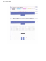
<Button and LCD test procedures>
Confirm the operation after replacement of the operation panel unit or LCD unit.
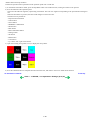
1) In the button and LCD test mode, press the Stop/Reset button. The LCD turns blue, waiting for a button to be pressed.
2) Press each button of the operation panel.
The LCD is divided into segments, representing each button. The color of a segment corresponding to the pressed button changes to
red.
When all the buttons are pressed, the entire LCD changes to a full red screen.
The buttons to be pressed are:
- Paper Feed Switch button
- COPY button
- SCAN button
- MEMORY CARD button
- Menu button
- Back button
- Photo Index Sheet button
- Settings button
- OK button
- Black button
- Color button
- Up / down / left / right cursor buttons
3) Open the scanning unit (printer cover) to display the color pattern.
4) Press the ON/OFF button to complete the button and LCD test, and return to the service mode menu selection.
To the table of contents
To the top
<Part 1: 3. REPAIR; 3-3. Adjustment / Settings (6) to (9)>
1-30
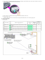
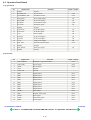
3-4. Verification Items
(1) Service test print
<EEPROM information contents>
On the service test print (sample below), confirm the EEPROM information as shown below. (The information is printed in the top and
middle areas of the printout.)
- Top area:
MP510: Model name
M = x.xx: ROM version
D = xxx.x: Main ink absorber counter value (%)
USB (xxxxxx): USB serial number
- Below the solid print patterns in each color:
JPN: Destination
- Middle area:
FA = xx xx xx, Temp: Reserved for plant use
AB (C = OK M = ...): Ink system function check result
<Print check items>
On the service test print (sample below), confirm the following items:
- Check 1, top of form accuracy: The lines shall not extend off the paper.
- Check 2, EEPROM information
- Check 3, nozzle check pattern: Ink shall be ejected from all nozzles.
- Check 4, check pattern for uneven printing due to carriage movement or line feeding (standard mode): There shall be no
remarkable unevenness.
- Check 5, check pattern for uneven printing due to carriage movement or line feeding (highest print quality mode): There shall
be no remarkable unevenness.
- Check 6, automatic print head alignment sensor correction: The results shall be OK.
1-31
<Service test print sample>
1-32
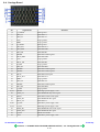
(2) EEPROM information print
<How to read EEPROM information print>
Print sample:
1: MP510 2: JPN 3: V1.01
4: ST=2006/01/28-18:30 5: LPT=2006/05/01-12:09
6: ER(ER0=1300 ER1=5100) 7: P_ON(S=00009) 8: MSD(002)
9: IF(USB1=1) 10: PC(M=002 R=000 T=001 D=009 C=000)
11: D=020.1 Ps=001.0
12: TPAGE(TTL=00162 COPY=00000)
13:CLT(006/01/28-18:38)
14: CH=00002 15: CT(BK=012 M=001 C=001 Y=013)
16: IS(PBK=2 BK=0 Y=2 M=0 C=0)
17: M_REG=0 A_REG=1
18: CDIN(PB=000 OPB=000) 19:BTIN=1
20: PAGE(All=00142 PP=00140 HR+MP=00000 PR+SP+SG=00002 GP=00000 PC=00000 EV=00000)
21: UCPAGE(All=00020)
22: CDPAGE(All=00000)
23: EDGE=00009 24: L=00008 25:BTPAGE=00000 26:EJ=1
27: INK_OFF(BK=0 M=0 C=1 Y=1)
28:Head TempBK=28.0 29:Head TempC=26.5 30:Env Temp=24.0
<Direct>
31: LG=01 Japanese
32: CDI=007 33: CDP=002
34: CDD-PR(L=000 2L=000 PC=000 A4=000)
35: CDD-SP(L=000 2L=000 PC=000 A4=000)
36: CDD-MP(L=000 2L=000 PC=000 A4=000)
37: DCD-PP(L=000 2L=000 PC=000 A4=000)
38: DCD-FPP(L=000 2L=000 PC=000 A4=000)
39: DCD-MPP(L=000 2L=000 PC=000 A4=000)
40:PrnB=000
41: SC=000 42: Seal=000
<Scanner>
43: SC=00005 44:SCAN_ER(ER0=0000 ER1=0000)
45: SC-dpi(75=00000 150=00000 300=00005 600=00000 1200=00000 2400=00000)
46: SG(GY=00003 CL=00002)
<Copy>
47: MCASF(PP=00000 SP+PR+GP=00000 OTH=00000)
48: CCASF(PP=00000 HR+MP=00000 PR+SP+SG=00000 GP=00000 PC=00000)
1-33
Printed items:
1. Model name 2. Destination 3. ROM version 4. Installation date & time 5. Last printing date & time
6. Operator call/service call error record
7. Power-on count (soft) 8. Longest period where printing stops (days)
9. Connected I/F (USB2) 10. Purging count (manual/deep cleaning/timer/dot count/ink tank and print head replacement)
11. Main ink absorber counter value (%), borderless-print ink absorber counter value (%)
12. Total print pages (total, copy pages)
13. Cleaning date & time (BK/CL)
14. Print head replacement count 15. Ink tank replacement count (BK/M/C/Y)
16. Ink status (BK/Y/M/C) => 0 (High) / 1 (Middle) / 2 (Low) / 3 (Empty)
17. Manual print head alignment by user, automatic print head alignment by user
18. Camera Direct Print-supported device connection record (PB = Canon PictBridge-supported camera, OPB = Other PictBridgesupported camera)
19. Bluetooth device connection record
20. ASF feed pages (total, plain paper, High Resolution Paper & Matte Photo Paper, Photo Paper Pro & Photo Paper Plus Glossy &
Photo Paper Plus Semi-gloss, Glossy Photo Paper, postcard, envelope)
21. Front feeder feed pages (total)
22. Camera Direct print pages (total)
23. Borderless print pages 24. L size and 4x6 print pages 25. Print pages via Bluetooth connection 26. Paper eject roller correction
value (not used in servicing)
27. Disabling of the remaining ink amount detection function (BK/M/C/Y)
28. Print head temperature (BK) 29. Print head temperature (CL) 30. Internal temperature
<Direct>
31. Language 32. Memory card use count 33. Total Card Direct print pages
34. Card Direct print pages: Photo Paper Pro (4 x 6, 5 x 7, Japanese post card, A4)
35. Card Direct print pages: Photo Paper Plus Glossy (4 x 6, 5 x 7, Japanese post card, A4)
36. Card Direct print pages: Matte Photo Paper (4 x 6, 5 x 7, Japanese post card, A4)
37. Camera Direct print pages: Photo Paper (4 x 6, 5 x 7, Japanese post card, A4)
38. Camera Direct print pages: Fast Photo Paper (4 x 6, 5 x 7, Japanese post card, A4)
39. Camera Direct print pages: Matte Photo Paper (4 x 6, 5 x 7, Japanese post card, A4)
40. Print Beam print pages 41. Business Card and Credit Card size paper print pages 42. Sticker sheet print pages
<Scanner>
43. Total scan count
44. The last 2 errors (including user errors and copy scan errors. Even if the same errors occur, they are recorded individually.)
45. Scan count by scanning resolution (75, 150, 300, 600, 1200, 2400 dpi)
46. Scan count by scanning gradation (grayscale, color)
<Copy>
47. Monochrome copy pages fed via the ASF (plain paper, Photo Paper Plus Glossy & Photo Paper Pro & Glossy Photo Paper, other)
48. Color copy pages fed via the ASF (plain paper, High Resolution Paper & Matte Photo Paper, Photo Paper Pro & Photo Paper Plus
Glossy & Photo Paper Plus Semi-gloss, Glossy Photo Paper, postcard)
To the table of contents
To the top
<Part 1: 3. REPAIR; 3-4. Verification Items>
1-34
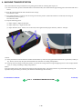
4. MACHINE TRANSPORTATION
This section describes the procedures for transporting the machine for returning after repair, etc.
1) In the service mode, press the ON/OFF button to finish the mode, and confirm that the paper lifting plate of the sheet feed unit is
raised.
2) Keep the print head and ink tanks installed in the carriage.
See Caution 1 below.
3) Turn off the machine to securely lock the carriage in the home position. (When the machine is turned off, the carriage is
automatically locked in place.)
See Caution 2 below.
4) Tape the following points:
(1) Paper support: Right and left sides
(2) Paper output tray: Right and left sides
(3) Paper thickness lever: Set the lever to the left (for the regular head-to-paper distance), and fix it with tape.
Caution:
(1) If the print head is removed from the machine and left alone by itself, ink (the pigment-based black ink in particular) is likely to
dry. For this reason, keep the print head installed in the machine even during transportation.
(2) Securely lock the carriage in the home position, to prevent the carriage from moving and applying stress to the carriage flexible
cable, or causing ink leakage, during transportation.
Memo:
If the print head must be removed from the machine and transported alone, attach the protective cap (used when the packing was
opened) to the print head (to protect the print head face from damage due to shocks).
To the table of contents
To the top
<Part 1: 4. MACHINE TRANSPORTATION>
1-35
Part 2
TECHNICAL REFERENCE
1. NEW TECHNOLOGIES
(1) Paper thickness lever (at the bottom front of the machine)
The head-to-paper distance can be adjusted using the paper thickness lever.
Smearing on printouts due to the print head contacting the paper, etc. may be solved by setting the paper thickness lever to the right (for
thick paper, envelope, and T-shirt transfer), regardless of the paper type.
(2) Remaining ink amount detection function
The machine has a function to detect the remaining ink amount.
Detection method: Optical method and dot count
Display method: Displayed on the Status Monitor
Level 1: Approx. 70% of ink remaining, status display only
Level 2: Approx. 40% of ink remaining, status display only
Level 3: Indication of "!" mark, "Ink low" warning
Level 4: Indication of "X" mark, "No ink" error (ink may have run out)
By pressing the Stop/Reset button, printing can be continued without replacing the applicable ink tank(s), though printouts
may be faint.
Level 5: Indication of "X" mark, "No ink" error (ink has run out)
By pressing the Stop/Reset button for 5 seconds or longer, the function to detect the remaining ink amount is disabled, and
printing can be continued without replacing the applicable ink tank(s).
After this operation, it is recorded in the EEPROM that the function to detect the remaining ink amount was disabled.
Printing with an empty ink tank will cause a problem. Promptly replace the applicable ink tank(s).
(3) Two-way paper feeding
Paper can be fed either from the auto sheet feeder or from the front feeder.
The auto sheet feeder is selected at default.
- Auto sheet feeder: All the supported types and sizes of paper can be fed.
- Front feeder: Only A4, B5, and Letter size plain paper can be fed.
(4) Print head alignment
Since it is NOT necessary to perform print head alignment at setup or installation of the machine, the function is only briefly introduced
at the installation.
If print quality is not satisfying (such as dot mis-alignment on a line), perform print head alignment.
Two types of print head alignment are available.
- Automatic print head alignment:
Perform via the machine operation panel, using the Print Head Alignment Sheet.
Print the first page of the Print Head Alignment Sheet in the manual print head alignment mode first, then fill in the applicable
circles on the sheet, and scan the sheet.
In automatic print head alignment, only the first page of the Print Head Alignment Sheet is used.
If automatic print head alignment is not effective, perform manual print head alignment.
Note: If all the necessary circles are not filled in, or the alignment sheet is not placed properly on the platen glass for scanning, the
automatic print head alignment error will occur. In such a case, start from printing a blank form of the Print Head Alignment
Sheet again.
- Manual print head alignment:
Perform via the machine operation panel or from the MP driver.
To the table of contents
To the top
<Part 2: 1. NEW TECHNOLOGIES>
2-1
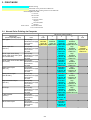
2. CLEANING MODE AND AMOUNT OF INK PURGED
To prevent printing problems due to bubbles, dust, or ink clogging, print head cleaning is performed before the start of printing (when the
cleaning flag is on), except in the following cases:
- Cleaning on arrival: Performed when the scanning unit (printer cover) is closed.
- Manual cleaning / deep cleaning: Performed manually.
<Cleaning mode list>
Black: Pigment-based black
Color: Dye-based cyan, magenta, yellow
Condition
On arrival of the
machine
Amount of ink used (g)
(in the normal
temperature/humidity
environment)
Details
First to third cleaning after shipped from the
plant.
0.50 (Black)
1.12 (Color)
Black only for the 3rd
cleaning.
(All in sequence)
Est. required time
(sec.)
(not including the
time of opening the
caps)
97
47 for the 3rd
cleaning
0.20 (Black)
46 (Black)
(Black)
When the specified number of dots are printed
since the previous Black cleaning.
Timer cleaning - 0*1
(Black only)
If 24 to 60 hours have elapsed since the previous
Black cleaning till the start of the next printing.
0.20 (Black)
46 (Black)
Timer cleaning - 1
(Black only)
If 60 to 240 hours have elapsed since the previous
Black cleaning till the start of the next printing.
Timer cleaning - 2*2
(All in
sequence/Black/Color)
If 240 to 336 hours have elapsed since the
previous Black/Color cleaning till the start of the
next printing.
0.20 (Black)
46 (Black)
36 (Color)
Timer cleaning - 3
If 336 to 1,080 hours have elapsed since the
previous Black/Color cleaning till the start of the
next printing.
0.54 (Black)
If 1,080 to 2,160 hours have elapsed since the
previous Black/Color cleaning till the start of the
next printing.
0.77 (Black)
If 2,160 to 4,320 hours have elapsed since the
previous Black/Color cleaning till the start of the
next printing.
1.39 (Black)
0.79 (Color)
Dot count cleaning
(All in sequence)
Timer cleaning - 4
(All in sequence)
Timer cleaning - 5
(All in sequence)
Timer cleaning - 6
(All in sequence)
If 4,320 or longer hours have elapsed since the
previous Black/Color cleaning till the start of the
next printing.
At print head
replacement
When the print head is removed and installed.
0.46 (Color)
37 (All in sequence)
83
0.79 (Color)
85
0.79 (Color)
88
88
0.50 (Black)
97
1.12 (Color)
(All in sequence)
At ink tank
replacement*3
When an ink tank is replaced (without the print
head removal or re-installation)
0.33 (Black)
81 (All in sequence)
0.79 (Color)
47 (Black)
51 (Color)
(Black/Color/All in
sequence)
Manual cleaning
(Black/Color/All at the
same time)
Deep cleaning
(Black/Color/All at the
- Via the operation panel (All at the same time
only)
0.20 (Black)
0.46 (Color)
37 (All at the same
time)
46 (Black)
- Via the MP driver (Selectable from Black,
Color, or All at the same time)
36 (Color)
Via the MP driver (Selectable from Black, Color, 1.63 (Black)
0.79 (Color)
or All at the same time)
89 (All at the same
time)
2-2
54 (Black)
52 (Color)
same time)
If the print head has not
been capped before
power-on
(All in sequence)
0.33 (Black)
81 (All in sequence)
0.79 (Color)
*1: When 24 to 60 hours have elapsed since the previous Black cleaning, timer cleaning - 0 is performed. However, this
cleaning will be conducted up to 5 times from the machine installation, and no further timer cleaning - 0 will be performed.
*2: The period of time since the previous cleaning is counted by Black and Color separately. For this reason, the cleaning mode
may differ according to Black or Color.
*3: When only the black ink tank is replaced, Black cleaning is performed. One of the color ink tanks is replaced, Color
cleaning is performed. Both the black and color ink tanks are replaced, All-at-the-same-time cleaning is performed.
To the table of contents
To the top
<Part 2: 2. CLEANING MODE AND AMOUNT OF INK PURGED>
2-3
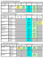
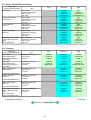
3. PRINT MODE
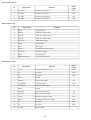
Default setting
Selectable in the printer driver Main tab
Selectable after clicking Custom in the Main tab
Ink used PigBk: PGI-5BK
C: CLI-8C
M: CLI-8M
Y: CLI-8Y
CLI-8C (small
c:
droplet)
CLI-8M (small
m:
droplet)
Print control
Bi: Bi-directional
Uni: Uni-directional
3-1. Normal Color Printing via Computer
MP driver Custom setting
3
2
Paper type
(Canon specialty paper)
Plain paper
5
4
1
Item
Fast
Fine
Print quality
Custom
Fast
Standard
High
Resolution HxV (dpi) 300x300
600x600
600x600
600x600
Print control
1 pass, Bi
1 pass, Bi
1 pass, Bi
4 passes, Bi
Ink used
PigBk/C/M/Y PigBk/C/M/Y PigBk/C/M/Y PigBk/C/M/Y/c/m
Photo Paper Pro
Print quality
Standard
High
Custom
(PR-101)
Resolution HxV (dpi)
600x600
600x600
600x600
Print control
4 passes, Bi
6 passes, Bi 16 passes, Bi
Ink used
C/M/Y/c/m
C/M/Y/c/m
C/M/Y/c/m
Photo Paper Plus Glossy
Print quality
Standard
High
Photo Paper Plus Semi-gloss
Resolution HxV (dpi)
600x600
600x600
(PP-101/SG-201)
Print control
4 passes, Bi
6 passes, Bi
Ink used
C/M/Y/c/m
C/M/Y/c/m
Photo Paper Plus Double Sided Print quality
Standard
High
(PP-101D)
Resolution HxV (dpi)
600x600
600x600
Print control
4 passes, Bi
6 passes, Bi
Ink used
C/M/Y/c/m
C/M/Y/c/m
Matte Photo Paper
Print quality
Standard
High
(MP-101)
Resolution HxV (dpi)
600x600
600x600
Print control
4 passes, Bi
6 passes, Bi
Ink used
C/M/Y/c/m
C/M/Y/c/m
Glossy Photo Paper
Print quality
Standard
High
(GP-401/501)
Resolution HxV (dpi)
600x600
600x600
Print control
4 passes, Bi
6 passes, Bi
Ink used
C/M/Y/c/m
C/M/Y/c/m
High Resolution Paper
Print quality
Standard
High
(HR-101)
Resolution HxV (dpi)
600x600
600x600
Print control
4 passes, Bi
6 passes, Bi
Ink used
C/M/Y/c/m
C/M/Y/c/m
Envelope
Print quality
Standard
High
Resolution HxV (dpi)
600x600
600x600
Print control
3 passes, Bi
4 passes, Bi
Ink used
PigBk/C/M/Y PigBk/C/M/Y/c/m
T-Shirt transfer
Print quality
Standard
(TR-301)
Resolution HxV (dpi)
600x600
Print control
6 passes, Bi
Ink used
C/M/Y
Other Photo Paper
Print quality
Standard
Resolution HxV (dpi)
600x600
Print control
8 passes, Bi
Ink used
C/M/Y/c/m
2-4
3-2. Normal Grayscale Printing via Computer
MP driver Custom setting
Paper type
(Canon specialty
paper)
Plain paper
Envelope
Item
Print quality
Resolution HxV (dpi)
Print control
Ink used
Print quality
Resolution HxV (dpi)
Print control
Ink used
5
Fast
4
3
2
Custom
300x300
1 pass, Bi
PigBk
Fast
600x600
1 pass, Bi
PigBk
Standard
600x600
1 pass, Bi
PigBk
Standard
600x600
2 passes, Uni
PigBk
High
600x600
4 passes, Bi
PigBk
High
600x600
4 passes, Uni
PigBk
1
Fine
3-3. Borderless Printing via Computer
MP driver Custom setting
Paper type
(Canon specialty
paper)
Plain paper
Photo Paper Pro
(PR-101)
Photo Paper Plus
Glossy
Photo Paper Plus
Semi-gloss
(PP-101/SG-201)
Photo Paper Plus
Double Sided
(PP-101D)
Matte Photo Paper
(MP-101)
Glossy Photo Paper
(GP-401/501)
Other Photo Paper
Item
Print quality
Resolution HxV (dpi)
Print control
Ink used
Print quality
Resolution HxV (dpi)
Print control
Ink used
Print quality
Resolution HxV (dpi)
Print control
Ink used
5
Fast
Print quality
Resolution HxV (dpi)
Print control
Ink used
Print quality
Resolution HxV (dpi)
Print control
Ink used
Print quality
Resolution HxV (dpi)
Print control
Ink used
Print quality
Resolution HxV (dpi)
Print control
Ink used
4
3
2
Standard
600x600
2 passes, Bi
C/M/Y
Standard
600x600
4 passes, Bi
C/M/Y/c/m
Standard
600x600
4 passes, Bi
C/M/Y/c/m
High
600x600
6 passes, Bi
C/M/Y/c/m
High
600x600
6 passes, Bi
C/M/Y/c/m
Standard
600x600
4 passes, Bi
C/M/Y/c/m
Standard
600x600
4 passes, Bi
C/M/Y/c/m
Standard
600x600
4 passes, Bi
C/M/Y/c/m
Standard
600x600
8 passes, Bi
C/M/Y/c/m
1
Fine
Custom
600x600
16 passes, Bi
C/M/Y/c/m
High
600x600
6 passes, Bi
C/M/Y/c/m
High
600x600
6 passes, Bi
C/M/Y/c/m
High
600x600
6 passes, Bi
C/M/Y/c/m
3-4. Manual Duplex Printing via Computer
MP driver Custom setting
Paper type
5
4
3
2
Item
(Canon specialty paper)
Fast
Plain paper
Print quality
Custom
Fast
Standard
High
Resolution HxV (dpi)
300x300
600x600
600x600
600x600
Print control
1 pass, Bi
1 pass, Bi
1 pass, Bi
1 pass, Bi
Ink used
PigBk/C/M/Y PigBk/C/M/Y PigBk/C/M/Y PigBk/C/M/Y/c/m
Plain paper,
Print quality
Standard
borderless printing
Resolution HxV (dpi)
600x600
Print control
2 passes, Bi
Ink used
C/M/Y
Photo Paper Plus Glossy Print quality
Standard
High
Double Sided
Resolution HxV (dpi)
600x600
600x600
(PP-101D)
Print control
4 passes, Bi
6 passes, Bi
Ink used
C/M/Y/c/m/k
C/M/Y/c/m/k
2-5
1
Fine
3-5. Card / Camera Direct Printing
Paper type
(Canon specialty paper)
Plain paper
Glossy Photo Paper
(GP-401/501)
Photo Paper Pro
(PR-101)
Matte Photo Paper
(MP-101)
Photo Paper Plus Glossy
Photo Paper Plus Semigloss
(PP-101/SG-201)
Fast
Item
Print quality
Resolution HxV (dpi)
Print control
Ink used
Print quality
Resolution HxV (dpi)
Print control
Ink used
Print quality
Resolution HxV (dpi)
Print control
Ink used
Print quality
Resolution HxV (dpi)
Print control
Ink used
Print quality
Resolution HxV (dpi)
Print control
Ink used
Standard
High
Standard
600x600
1 pass, Bi
PigBk/C/M/Y
Standard
600x600
4 passes, Bi
C/M/Y/c/m
Standard
600x600
4 passes, Bi
C/M/Y/c/m
Standard
600x600
4 passes, Bi
C/M/Y/c/m
Standard
600x600
4 passes, Bi
C/M/Y/c/m
High
600x600
4 passes, Bi
PigBk/C/M/Y/c/m
High
600x600
6 passes, Bi
C/M/Y/c/m
High
600x600
6 passes, Bi
C/M/Y/c/m
High
600x600
6 passes, Bi
C/M/Y/c/m
High
600x600
6 passes, Bi
C/M/Y/c/m
3-6. Copying
Paper type
(Canon specialty paper)
Plain paper
Single sided, B&W
(Borderless printing not
supported)
Plain paper
Single sided, Color
(Borderless printing not
supported)
Glossy Photo Paper
(GP-401/501)
Single sided, B&W/Color
Photo Paper Pro
(PR-101)
Single sided, B&W/Color
Matte Photo Paper
(MP-101)
Single sided, B&W/Color
Photo Paper Plus Glossy
Photo Paper Plus Semigloss
(PP-101/SG-101)
Single sided, B&W/Color
Item
Resolution HxV (dpi)
Print control
Ink used
Fast
Standard
High
300x300
1 pass, Bi
PigBk
600x600
1 pass, Bi
PigBk
600x600
4 passes, Bi
PigBk
Resolution HxV (dpi)
Print control
Ink used
300x300
1 pass, Bi
PigBk/C/M/Y
600x600
1 pass, Bi
PigBk/C/M/Y
600x600
4 passes, Bi
PigBk/C/M/Y/c/m
Resolution HxV (dpi)
Print control
Ink used
600x600
4 passes, Bi
C/M/Y/c/m
600x600
6 passes, Bi
C/M/Y/c/m
Resolution HxV (dpi)
Print control
Ink used
600x600
4 passes, Bi
C/M/Y/c/m
600x600
6 passes, Bi
C/M/Y/c/m
Resolution HxV (dpi)
Print control
Ink used
600x600
4 passes, Bi
C/M/Y/c/m
600x600
6 passes, Bi
C/M/Y/c/m
Resolution HxV (dpi)
Print control
Ink used
600x600
4 passes, Bi
C/M/Y/c/m
600x600
6 passes, Bi
C/M/Y/c/m
To the table of contents
To the top
<Part 2: 3. PRINT MODE>
2-6
4. FAQ (Problems Specific to the MP510 and Corrective Actions)
No.
1
2
3
4
5
*
Function
Phenomenon
Cause
Corrective action
Possible call or
complaint
Ink tank installed
A Installation in a wrong
position
The ink tank is installed in Open the scanning unit
- Ink tank installation
a wrong position.
(printer cover), and install error.
the ink tank(s) properly.
Print head
B Installation installation error
Insufficient allowance of Remove and re-install the - Print head
the print head positioning print head.
installation error.
part.
B
C
B
No paper feeding - Paper feeding
from the ASF
- Postcard
The paper feed roller slips 1. Perform paper feed
- Paper out error
on the paper at paper
roller cleaning.
- Paper cannot be fed
feeding.
2. Clean the paper feed
- Cannot print
roller with premoistened wipe or
moistened cloth.
3. Correct paper curl. If
the problem persists,
adjust the printer
guide to leave approx.
0.5 mm between the
guide and the paper
edge.
Multi-feeding
- In the high
temperature and
high humidity
environment
In the high temperature
1. Fan the paper before
- Multiple sheets of
and high humidity
setting them.
paper are fed
environment, the
simultaneously.
2. In case of PR-101, set
frictional force between
the paper sheet by
- Blank paper is
the front and back sides of
sheet.
ejected.
paper becomes high, and
3. Recommend use of the
sheets stick to each other,
ASF for printing on
contributing to multiboth sides of paper
feeding.
(manual duplex
printing).
Envelope not
feeding
- Envelope
The paper feed roller slips 1. Perform paper feed
- Paper out error
on the paper at paper
roller cleaning via the - Paper cannot be fed
feeding.
operation panel.
- Cannot print
Note:
2. Clean the paper feed
roller with preDepending on the paper
moistened wipe or
lots.
moistened cloth.
3. Reduce the number of
envelopes set in the
ASF.
4. Flatten the envelope
(with a pen).
5. If the paper support is
extended, retract it.
Paper feed
Paper feed
Paper feed
Paper jam
6
Condition
C
Paper feed
1. As the LF roller slips
on the paper, the paper
is not fed, causing the
jam error at paper
ejecting.
2. The printer guide is not
properly set.
3. The paper source
where the paper is set
is not selected.
4. When the tab of the
paper support is
raised, the Legal size
paper hits it before the
paper is completely
ejected.
5. If the rear cover is not
properly attached, the
edge of paper contacts
the rear cover during
2-7
1. Remove the jammed
- Paper jam error
paper from the paper - Paper cannot be fed
pick-up side.
- Cannot print
2. Confirm that the
printer guide is
properly adjusted.
3. Confirm that the paper
source is properly
selected.
4. For Legal size paper,
close the tab of the
output paper support.
5. In case of a paper jam
in the front feeder,
confirm that the rear
cover securely fits in
place after the paper
previously jammed in
the front feeder was
removed.
paper feeding, resulting in
a paper jam.
7
B
8
B
9
C
Smearing on
printed side
When paper is curled, the 1. Correct the paper curl. - Smear on the
edge of paper rises,
printed side of
2. Recommend printing
causing the print head to
paper
in the print quality
rub against the printed
- Cannot print
assurance area.
surface of paper, resulting
properly
in smearing.
- Paper edge crease
Smearing on the
back side of
paper, or on the
address side of
postcards
When borderless printing 1. Perform Bottom plate
is performed
cleaning via the
continuously, ink mist
operation panel.
attaches to the platen ribs,
Change the paper in
and is transferred to the
each Bottom plate
backside of the following
cleaning.
paper.
The cleaning can end
when paper does not
get any smearing.
2. Clean the platen ribs
with cotton swabs,
etc.
Horizontal lines
or uneven print
density at the
trailing edge of
paper
When the paper end
1. Recommend printing - Cannot print to the
comes off the pinch roller,
in the print quality
bottom edge of
printing is performed
assurance area.
paper
without the paper being
2. Change the print
- Lines or uneven
held, preventing the ink
print density appear
quality from Standard
drops from being ejected
in the trailing edge
to High mode.
in the correct positions,
of paper
3. Try other paper (PPresulting in unevenness.
- Cannot print
101).
properly
Print
results
Print
results
Print
results
Error in print
head alignment
10
11
C Installation
B
Other
- Automatic print 1. Some circles on the
head alignment
Print Head Alignment
using the Print
Sheet were not filled
Head Alignment
in.
Sheet
2. The sheet was not
placed properly on the
platen glass.
Removal of the - At removal of the Since the collars are
front feeder guide rear cover
loosely attached, they are
collar
easy to be removed when
touched.
Press the OK button to
clear the error.
<Photo Paper Plus
Double Sided>
Smears on the
already printed side
when printing the
other side
<When printing the
address side of
postcards>
Smears on the
address side
<When printing the
message side of
postcards>
Smears on the
backside
- Error in print head
alignment
Perform print head
alignment again, from
printing of a blank form
of the Print Head
Alignment Sheet. When
starting over print head
alignment, always start
from printing out the
blank form (scanning of
the filled-in sheet alone
cannot be performed).
Attach the removed part.
Advise a user not to
contact the collars when
the rear cover is opened.
- A part is removed
* Occurrence level:
A: The symptom is likely to occur frequently. (Caution required)
B: The symptom may occur under certain conditions, but likeliness is assumed very low in practical usage.
C: The symptom is unlikely to be recognized by the user, and no practical issues are assumed.
To the table of contents
To the top
<Part 2: 4. FAQ>
2-8
Part 3
APPENDIX
1. BLOCK DIAGRAM
1-1. PIXMA MP510
Link to a PDF file for printing
To the table of contents
To the top
<Part 3: 1. BLOCK DIAGRAM>
3-1
2. CONNECTOR LOCATION AND PIN LAYOUT
2-1. Logic Board Ass'y
J301 (Print Head 1/3 [Carriage Unit])
No.
Signal name
Function
1 to 4
VH_GND
Head drive ground
5 to 9
VH
Head driver power supply +24V
VH_GND
Head drive ground
10 to 14
Input /
Output
OUT
-
J302 (Print Head 2/3 [Carriage Unit])
No.
Signal name
Function
Input /
Output
1 to 2
HVDD
Head logic power supply +3.3V
OUT
3 to 5
VH
Head logic power supply +24V
OUT
6
SGND
System ground
7
B_DIA
Diode sensor anode B
8
SGND
System ground
9
A_DIA
Diode sensor anode A
10
SGND
System ground
11
ENC_OUT_A
Encoder output signal A
12
SGND
System ground
13
ENC_OUT_B
Encoder output signal B
14
ENC_PWR
Encoder drive power supply +3.3V
3-2
IN
IN
IN
IN
OUT
J303 (Print Head 3/3 [Carriage Unit])
No.
Signal name
Function
Input /
Output
1
AB_PWR
Ink tank sensor chip power supply
OUT
2
AB_DATA
Ink tank sensor data power supply
BUS
3
AB_PWR
Ink tank sensor chip power supply
OUT
4
AB_CLK
Ink tank sensor data transfer clock signal
BUS
5
THERMO
Carriage temperature sensor signal
6
H_ENB2
Head heat enable signal 2
OUT
7
HD9_Y2
Head data (Y2)
OUT
8
HD13_C2
Head data (C2)
OUT
9
HD11_M2
Head data (M2)
OUT
10
HD12_SC2
Head data (SC2)
OUT
11
HD10_SM2
Head data (SM2)
OUT
12
ROM_DIO
Head EEPROM input - output data
13
SGND
System ground
14
H_CLK
Head data transfer clock signal
15
SGND
System ground
16
ROM_SK
Head EEPROM serial clock signal
OUT
17
HLAT
Head data latch signal
OUT
18
HD8_Y1
Head data (Y1)
OUT
19
ROM_CS
Head EEPROM chip select signal
OUT
20
HENB1
Head heat enable signal1
OUT
21
HENB3
Head heat enable signal 3
OUT
22
HD2_C1
Head data (C1)
OUT
23
HENB0
Head heat enable signal0
OUT
24
HD0_K1
Head data (BK1)
OUT
25
HD4_M1
Head data (M1)
OUT
26
HD1_K2
Head data (BK2)
OUT
27
HD5_SM1
Head data (SM1)
OUT
28
HD3_SC1
Head data (SC1)
OUT
IN
IN/OUT
OUT
-
J501 (LF Encoder)
No.
Signal name
Function
1
GND
Ground
2
ENCA
LF encoder phase A
3
VSEN
Sensor power supply +3.3V
4
ENCB
LF encoder phase B
Input /
Output
-
3-3
IN
OUT
IN
J502 (Ink Sensor / Ink Tank Sensor)
No.
Signal name
Function
1
SNS_AB
Ink tank sensor signal
2
VSEN_3.3V
Ink tank sensor power supply
3
SNS_INK
Ink sensor signal
4
GND
Ground
5
INK_PWM
Ink tank sensor signal
Input /
Output
IN
OUT
IN
IN
J503 (Power Supply Unit)
No.
Signal name
Function
1
VM
Motor power supply +32V
2,4
GND
Ground
3
VH
Head power supply +24V
5
PW_DWN
Power supply control signal
Input /
Output
OUT
IN
OUT
J505 (ASF_PE Sensors)
No.
Signal name
Function
Input /
Output
1
SES_ASF
ASF sensor
IN
2
SES_PE
PE sensor
IN
3
GND
Ground
4
VSEN_3.3V
Sensor power supply +3.3V
OUT
J507 (Main Cam Sensor)
No.
Signal name
Function
1
VSEN_3.3V
Sensor power supply +3.3V
2
GND
Ground
3
SNS_MAIN_CAM
Main cam sensor
Input /Output
OUT
-
3-4
IN
J601 (Operation Panel / LCD)
No.
Signal name
Function
Input /
Output
1
GND
Ground
-
2
PANEL_RSTX
Panel reset signal
3
GND
Ground
4
PANEL_INT
Panel interruption signal
5
+3.3V
LCD drive power supply +3.3V
OUT
6
LVCLK-
LV clock-
OUT
7
LVCLK+
LV clock+
OUT
8
5V
Power supply +5V
OUT
9
LVDATA-
LV data-
OUT
10
LVDATA+
LV data+
OUT
11
GND
Ground
12
RXD
Reception signal
13
TXD
Transmission signal
14
ERROR_LED
Alarm LED
IN
15
POWER_LED
Power LED
IN
16
STOP_SW
Stop/Reset switch
IN
17
POW_SW
Power switch
IN
18
GND
Ground
OUT
IN
IN
OUT
-
J701 (Carriage Motor)
No.
Signal name
Function
Input /
Output
1
CR_M
CR motor+
OUT
2
CR_MN
CR motor-
OUT
J702 (LF Motor)
No.
Signal name
Function
Input /
Output
1
LF_M
LF motor+
OUT
2
LF_MN
LF motor-
OUT
J703 (Purge Unit Motor)
No.
Signal name
Function
Input /
Output
1
PG_MA
PG motor phase A+
OUT
2
PG_MB
PG motor phase B+
OUT
3
PG_MAN
PG motor phase A-
OUT
4
PG_MBN
PG motor phase B-
OUT
3-5
J704 (Scanner Motor)
No.
Signal name
Function
Input /
Output
1
SC_MAN
Scanner motor phase A-
OUT
2
SC_MA
Scanner motor phase A+
OUT
3
SC_MB
Scanner motor phase B+
OUT
4
SC_MBN
Scanner motor phase B-
OUT
J801 (Scanner Unit)
Signal name
No.
Function
1
GND
Digital ground
2
LED_R
LED drive signal (Red)
3
LED_G
LED drive signal (Green)
4
LED_B
LED drive signal (Blue)
5
LED_Vcc
LED power supply
6
XPH1
Clock output
7
XTG
SH output
8
REV_V
CIS reference power supply
9
Vcc(3.3V)
CIS power supply
10
GND
Digital ground
11
XPH2(RES_SEL)
CIS resolution switch
J901 (Memory Card)
No.
Signal name
Function
Input /
Output
1
+3.3V
Drive power supply +3.3V
OUT
2
D-
D- signal
BUS
3
D+
D+ signal
BUS
4
GND
Ground
5
DOOR
Cover switch signal
6
CARD_RST
Card reset signal
7
CARD_INT
Card interruption signal
8
GND
Ground
9
IR_RXD
IrDA reception signal
IN
10
IR_TXD
IrDA transmission signal
IN
11
+5.0V
Drive power supply +5.0V
OUT
12
VBUS
PictBridge VBUS power supply
OUT
13
D-
D- signal
BUS
14
D+
D+ signal
BUS
15
S_GND
System ground
IN
OUT
IN
-
3-6
-
J902 (USB 2.0 I/F)
No.
Signal name
Function
Input /
Output
1
SNS_USB
USB VBUS power supply sensor
IN
2
D-
USB D- signal
BUS
3
D+
USB D+ signal
BUS
4
GND
Ground
-
5
L_GND
Logic ground
-
6
L_GND
Logic ground
-
7
L_GND
Logic ground
-
8
L_GND
Logic ground
-
To the table of contents
To the top
<Part 3: 2. CONNECTOR LOCATION AND PIN LAYOUT; 2-1. Logic Board Ass'y>
3-7
2-2. Card Slot Board
J1 (Logic Board)
No.
Signal name
Function
Input / Output
1
GND
Ground
-
2
DSC D+
Camera Direct D+ signal
IN/OUT
3
DSC D-
Camera Direct D- signal
IN/OUT
4
VBUS
PictBridge VBUS power supply
IN
5
+5.0V
Power supply
IN
6
Ir_TXD
IrDA reception signal
IN
7
Ir_RXD
IrDA reception signal
OUT
8
GND
Ground
9
INTX
Interruption signal
10
RESETX
Reset signal
11
COVER
Cover switch signal
12
GND
Ground
13
D+
D+ signal
IN/OUT
14
D-
D- signal
IN/OUT
15
+3.3V
Logic power supply
OUT
IN
OUT
-
IN
J2 (SmartMedia, Memory Stick, SD (MMC))
No.
Signal name
Function
Input / Output
入出力
1
SD_WPSW
SD write protect
2
SD_WP_GND
SD write protect ground
3
SD_CD
SD card detect
4
SD_CD_GND
SD card detect ground
5
SM_CDSW
SM card detect
6
SM_CDSW_GND
SM card detect ground
-
7
SM_VCC
SM logic power supply
OUT
8
SM_CDX
SM card detect
OUT
9
SM_D4
SM 16 bit data bus
3-8
IN
OUT
OUT
IN/OUT
10
SM_GND
SM ground
11
SM_D5
SM 16 bit data bus
IN/OUT
12
SM_D3
SM 16 bit data bus
IN/OUT
13
SM_D6
SM 16 bit data bus
IN/OUT
14
SM_D2
SM 16 bit data bus
IN/OUT
15
SM_D7
SM 16 bit data bus
IN/OUT
16
SM_D1
SM 16 bit data bus
IN/OUT
17
SM_LVD
SM low voltage detection
18
SM_D0
SM 16 bit data bus
IN/OUT
19
SD_DAT1
MMC/SD 16 bit data bus
IN/OUT
20
MS_GND
MS ground
21
SD_DAT0
MMC/SD 16 bit data bus
22
MS_BS
MS bus state
23
SD_GND
SD ground
24
MS_VCC
MS logic power supply
25
SD_CLK
MMC/SD clock
26
MS_DIO(D0)
MS 16 bit data bus
27
SD_VCC
SD logic power supply
28
Reserve(D2)
MS 16 bit data bus
29
SD_GND
SD ground
30
MS_INS
MS insertion detection
31
SD_CMD
MMC/SD command
IN/OUT
32
Reserve(D3)
MS 16 bit data bus
IN/OUT
33
MS_SCLK
MS system clock
34
SD_DAT3
MMC/SD 16 bit data bus
35
MS_VCC(D1)
MS logic power supply
36
SD_DAT2
MMC/SD 16 bit data bus
37
MS_GND
MS ground
-
38
SM_GND
SM ground
-
39
SM_WPX-IN
SM write protect
IN
40
SM_BSYX
SM busy
IN
41
SM_WEX
SM write enable
IN
42
SM_REX
SM read enable
IN
43
SM_ALE
SM address latch enable
IN
44
SM_CEX
SM chip enable
IN
45
SM_CLE
SM command latch enable
IN
46
SM_VCC
SM logic power supply
47
SM_GND
SM ground
48
SM_WPSW
SM write protect
49
SM_WPSW_GND
SM write protect ground
-
50
Frame_GND
Frame ground
-
51
Frame_GND
Frame ground
-
-
IN
IN/OUT
IN
OUT
IN
IN/OUT
OUT
IN/OUT
IN
IN
IN/OUT
IN
IN/OUT
OUT
-
3-9
IN
J3 (CompactFlash)
No.
Signal name
Function
Input / Output
1
GND
CF ground
-
2
CF_D3
CF 16 bit data bus
IN/OUT
3
CF_D4
CF 16 bit data bus
IN/OUT
4
CF_D5
CF 16 bit data bus
IN/OUT
5
CF_D6
CF 16 bit data bus
IN/OUT
6
CF_D7
CF 16 bit data bus
IN/OUT
7
CF_CS0X
CF chip select
8
GND(CF_A10)
Ground (CF 24 bit address bus)
-
9
GND(CF_ATASELX)
Ground (CF output enable)
-
10
GND(CF_A9)
Ground (CF 24 bit address bus)
-
11
GND(CF_A8)
Ground (CF 24 bit address bus)
-
12
GND(CF_A7)
Ground (CF 24 bit address bus)
-
13
VCC
CF logic power supply
14
GND(CF_A6)
Ground (CF 24 bit address bus)
-
15
GND(CF_A5)
Ground (CF 24 bit address bus)
-
16
GND(CF_A4)
Ground (CF 24 bit address bus)
-
17
GND(CF_A3)
Ground (CF 24 bit address bus)
-
18
CF_A2
CF 24 bit address bus
IN/OUT
19
CF_A1
CF 24 bit address bus
IN/OUT
20
CF_A0
CF 24 bit address bus
IN/OUT
21
CF_D0
CF 16 bit data bus
IN/OUT
22
CF_D1
CF 16 bit data bus
IN/OUT
23
CF_D2
CF 16 bit data bus
IN/OUT
24
CF_IOCS16X
Not used
IN/OUT
25
CF_CD2X
CF card detect
OUT
26
CF_CD1X
CF card detect
OUT
27
CF_D11
CF 16 bit data bus
IN/OUT
28
CF_D12
CF 16 bit data bus
IN/OUT
29
CF_D13
CF 16 bit data bus
IN/OUT
30
CF_D14
CF 16 bit data bus
IN/OUT
31
CF_D15
CF 16 bit data bus
IN/OUT
32
CF_CS1X
CF chip select
33
CF_VS1X
CF voltage sense
34
CF_IORDX
CF read strobe input - output
IN/OUT
35
CF_IOWRX
CF write enable input - output
IN/OUT
36
VCC(CF_WEX)
CF logic power supply (write enable)
IN
37
CF_INTRQ
CF interruption
IN
38
VCC
CF logic power supply
OUT
39
GND(CF_CSELX)
CF ground (chip select)
-
40
CF_VS2X
CF voltage sense
3-10
OUT
OUT
OUT
IN
IN
41
CF_RESETX
CF reset
42
CF_IORDY
CF ready input - output
43
CF_INPACKX
Not used
44
VCC(CF_REGX)
CF register select
45
CF_DASPX
Not used
-
46
CF_PDIAGX
Not used
-
47
CF_D8
CF 16 bit data bus
IN/OUT
48
CF_D9
CF 16 bit data bus
IN/OUT
49
CF_D10
CF 16 bit data bus
IN/OUT
50
GND
CF logic ground
-
51
PEG(FGND)
Not used
-
52
PEG(FGND)
Not used
-
IN
IN/OUT
IN
OUT
J4 (Digital Camera Connector)
No.
Signal name
Function
Input / Output
1
DSC_VBUS
PictBridge VBUS power supply
OUT
2
DSC D-
Camera Direct D- signal
IN/OUT
3
DSC D+
Camera Direct D+ signal
IN/OUT
4
DSC_SGND
Ground
-
5 to 8
DSC_FGND
Ground
-
J5 (IrDA Board)
No.
Signal name
Function
Input / Output
1
Ir_3.3V
Logic power supply
OUT
2
Ir_RXD
IrDA reception signal
IN
3
Ir_TXD
IrDA reception signal
OUT
4
Ir_GND
Ground
-
5
Ir_FGND
Ground
-
J301 (Memory Card Board)
No.
Signal name
Function
Input / Output
1
Ir_3.3V
Logic power supply
IN
2
Ir_RXD
IrDA reception signal
OUT
3
Ir_TXD
IrDA reception signal
IN
4
Ir_GND
Ground
-
5
Ir_FGND
Ground
-
To the table of contents
To the top
<Part 3: 2. CONNECTOR LOCATION AND PIN LAYOUT; 2-2. Card Slot Board>
3-11
2-3. Operation Panel Board
J1 (Logic Board)
No.
Signal name
Function
Input / Output
1
DGND
Ground
-
2
POWER_SW
Power switch
OUT
3
STOP/RESET_SW
Stop/Reset switch
OUT
4
LED_POW
Power LED display
IN
5
LED_ERR
Error LED display
IN
6
PN_RXD
Transmission signal
OUT
7
PN_TXD
Reception signal
8
DGND
Ground
9
LVDATA+
LCD data signal+
IN
10
LVDATA-
LCD data signal-
IN
11
+5V
Power supply
IN
12
LVCLK+
LCD clock signal+
IN
13
LVCLK-
LCD clock signal-
IN
14
+3.3V
Logic power supply
15
PNL_INT
Panel interruption signal
16
DGND
Ground
17
PNL_RSTX
Panel reset signal
18
DGND
Ground
IN
-
IN
OUT
IN
-
J2 (LCD Unit)
No.
Signal name
Function
Input / Output
1
LED_SHDNX
Backlight-on operation enable
OUT
2
LED_POW
Power supply
OUT
3
VDD
Power supply
OUT
4
Vss
Ground
-
5
LED_Vss
Ground
-
6
DB7
Display data 7
OUT
7
DB6
Display data 6
OUT
8
DB5
Display data 5
OUT
9
DB4
Display data 4
OUT
10
DB3
Display data 3
OUT
11
DB2
Display data 2
OUT
12
DB1
Display data 1
OUT
13
DB0
Display data 0
OUT
14
WDB
Write signal
OUT
15
RS0
Register select signal
OUT
16
RSTB
Reset signal
OUT
17
CS1B
Chip select signal
OUT
18
RDB
Power supply
OUT
To the table of contents
To the top
<Part 3: 2. CONNECTOR LOCATION AND PIN LAYOUT; 2-3. Operation Panel Board>
3-12
2-4. Carriage Board
No.
Signal name
Function
1,2
A_GNDH
Head ground
3
HD2_C1
Head data C1
4
HD8_Y1
Head data Y1
5
VSS
Logic ground
6
PBK1
Logic ground
7,8
B_GNDH
Head ground
9
HD3_SC1
Head data SC1
10
HD5_SM1
Head data SM1
11
HD4_M1
Head data M1
12
HENB1
Head heat enable signal 1
13
HD10_SM2
Head data SM2
14
VSS
Logic ground
15
HD11_M2
Head data M2
16
B_DiK
Logic ground
17
HD0_K1
Head data BK1
18
HENB0
Head heat enable signal 0
19
HENB3
Head heat enable signal 3
20
HLAT
Head data latch signal
21
HD12_SC2
Head data SC2
22
PBK2
Logic ground
23
HD9_Y2
Head data Y2
24
HENB2
Head heat enable signal 2
25
HD1_K2
Head data BK2
26
A_DiK
Logic ground
27,35
HVDD
Head logic power supply +3.3V
28
ROM_CS
Head EEPROM chip select signal
29
HCLK
Head data transfer clock signal
30
ROM_DO
Head EEPROM data signal
31
HD13_C2
Head data C2
32,40
B_VH2
Head drive power supply +24V
33,34
A_VH
Head logic power supply +24V
36
ROM_SK
Head EEPROM serial clock signal
37
ROM_DIO
Head EEPROM data signal
38
B_DiA
Diode senor anode
39
VHT
Head drive power supply +24V
To the table of contents
To the top
<Part 3: 2. CONNECTOR LOCATION AND PIN LAYOUT; 2-4. Carriage Board>
3-13
3. PIXMA MP510 SPECIFICATIONS
<Machine>
Type
Desktop serial color inkjet printer
Paper feeding method
Auto sheet feed (auto sheet feeder, front feeder)
Resolution
4,800 x 1,200dpi (Max.)
- 4 x 6, borderless printing: Approx. 47 sec. (PP-101 4x6, borderless printing, default settings)*
For reference:
Custom 5
Standard
Remarks
Black (Fine Black) 25ppm
13.9ppm
Paper feeding from the ASF
Color (Fine Color) 17ppm
10.4ppm
Paper feeding from the ASF
Throughput (target value)
* Based on Canon standard pattern. Print speed may vary depending on system configuration, interface,
software, document complexity, print mode, page coverage, type of paper used and does not take into
account data processing time on host computer.
Note: Notations for the Americas should be confirmed with the related marketing section of each sales
company in the Americas.
Printing direction
Bi-directional, uni-directional
Print width
Max. 203.2mm (215.9mm in borderless printing)
- Computer: USB 2.0 Hi-Speed, Bluetooth ver. 1.2 (optional)
Interface
- Camera Direct: PictBridge with a PictBridge-supported digital camera and digital video camera
- Mobile phone: IrDA 1.2, Bluetooth ver. 1.2 (optional), both for JPEG files only
Stacking
capacity
Max. 13 mm (Approx. 150 sheets of 64 g/m2 plain paper)
Paper weight
64 to 105 g/m2, Canon specialty paper 273 g/m2 at the maximum
Type
Size
Plain paper
Super White Paper
ASF paper
feed
specifications
Paper
specifications
Stacking capacity (sheets)
Approx. 150 (13mm)
SW-201
Legal
10
A4, Letter
Approx. 100 (13mm)
High Resolution Paper
HR-101N
A4, Letter
Approx. 80
Photo Paper Pro
PR-101
A4, Letter, 8x10
10
4x6, 4x8, Wide
20
10
Photo Paper Plus Glossy
PP-101
A4, Letter, 5x7
4x6
20
Photo Paper Plus Semi-gloss
SG-201/101
A4, Letter, 8x10
10
4x6
20
GP-401
A4, Letter
10
4x6, Credit Card
20
GP-501/502
A4, Letter
10
4x6
20
A4, Letter
10
Glossy Photo Paper
Matte Photo Paper
MP-101
4x6
20
Photo Paper Plus Double Sided PP-101D
A4, Letter, 5x7
1
Photo Stickers
PS-101
4x6
1
T-shirt Transfer
TR-301
A4
1
DL-size, COM#10
10
Envelope
Stacking
capacity
Max. 10 mm (Approx. 100 sheets of 64 g/m2 plain paper)
Front feeder
Paper weight 64 to 105 g/m2
paper feed
specifications
Paper
Plain paper (10 mm or less, approx. 100 sheets): A4, B5, Letter only
specifications
Detection functions
Scanning unit open, Presence of print head / ink tanks, Remaining ink amount (optical / dot count), Ink
tank position, Paper presence, Paper end sensor, Ink amount in the ink absorber, Internal temperature,
Paper lifting plate position, Paper feed roller position, Carriage position, Supported camera direct printing
device, Presence of memory card, Scanner home position
3-14
- Printing from a computer:
Acoustic noise
36 dB (A) (Photo Paper Pro, highest print quality settings, paper feeding from the ASF)
- Copying:
38.5 dB (A) (Photo Paper Pro, highest copy quality settings, paper feeding from the ASF)
During operation
Environmental requirements
Power supply
Non operation
Temperature
Humidity
Temperature
Humidity
5C to 35C (41F to 95F)
10%RH to 90%RH (no condensation)
0C to 40C (32F to 104F)
5%RH to 95%RH (no condensation)
Power supply voltage, frequency
Power consumption
(copy)*1
Standby
Power-off*2
AC 100 to 240V, 50/60Hz
Approx.25W
Approx. 2.0W
Approx. 0.8W
*1: When copying ISO/JIS-SCID N2 on A4 plain paper with the standard settings
*2: Scanner light turned off
External dimensions
- With the trays retracted: Approx. 444 (W) x 365 (D) x 171 (H)mm
- With the trays extended: Approx. 444 (W) x 627 (D) x 297 (H)mm
- With the scanning unit opened (max.): Approx. 444 (W) x 627 (D) x 435 (H)mm
Weight
Approx. 7.0 kg, including the print head and excluding the optional units
Related standards
(Machine)
Electromagnetic radiance:
VCCI, FCC, IC, CE Mark, Taiwan RPC, C-Tick, CCC (EMC), Korea MIC, Gost-R
Electrical safety:
Electrical Appliance and Material Safety Law (DENAN), UL, C-UL, CB Report, CE Mark, GS, GostR, FT, SASO, CCC, SPRING, Korea EK, IRAM (Argentine)
Environmental regulations:
RoHS (EU), WEEE (EU), Korea Package Recycle Law, Green Point (Germany), Energy Star, Eco
Mark, Law on Promoting Green Purchasing
Serial number location
The label is attached to the spur guide inside the printer.
Remaining ink amount
detection
Available (detection by optical method and dot count, enabled at default)
Paper type detection
Not available
Available
Print head alignment
- Automatic alignment: Perform via the operation panel, using the Print Head Alignment Sheet.
- Manual alignment: Perform via the operation panel, or from the MP driver Maintenance tab.
<Scanner>
Type
Flat bed scanner (scanning of a fixed document by a moving scanner head)
Sensor type
CIS (Contact Image Sensor)
Optical resolution
1,200 x 2,400 dpi (max.)
Scanning resolution (software
interpolation)
19,200 x 19,200 dpi (max.)
Gradation (input / output)
Grayscale: 16 bit / 8 bit
Color: 48 bit / 24 bit (RGB each color 16 bit / 8 bit)
Document size
Platen glass: A4 / Letter (Max.)
<Copy>
Copy quality
3 levels (Fast, Standard, High)
Intensity
9 levels (automatic intensity adjustment available)
Enlargement / reduction ratio
25 to 400%
Copy speed
A4 color document: Approx. 33 sec.
For reference:
- Monochrome copy: 25cpm
- Color copy: 17cpm
Note: - Document copy speed is based on copying the manuscript "ISO/IEC FCD24712:
Newsletter" (digital data printed by offset) using default settings on plain paper. Black text / color
(CPM) are based on "fast mode" setting using Canon standard pattern on plain paper. Copy speed
3-15
may vary depending on document complexity, copy mode, page coverage, type of paper used, etc. and
does not take into account warming up time.
- Notations for the Americas should be confirmed with the related marketing section of each sales
company in the Americas.
Document size
A4 / Letter (max.)
Enlargement / reduction
Preset ratio:
max. (400%), 4x6 -> LTR (212%), 5x7 -> LTR (170%), A5 -> A4 (141%), B5 -> A4 (115%), A4 ->
LTR (95%), A4 -> B5 (86%), A4 -> A5 (70%), min. (25%)
Zoom:
25 to 400% (in increments of 1%)
Number of continuous copies
Monochrome / color: 1 to 99 copies
<Direct printing>
Memory card drive
Compact Flash TYPE I/II (3.3V), Microdrive, SmartMedia Card (3.3V only, 1MB and
2MB not supported), Memory Stick, Memory Stick PRO, SD card, MultiMedia Card
Supported memory card (ver. 3.31), xD-Picture Card*, miniSD card*, Memory Stick Duo*, RS-MMC (ver.
3.31), Memory Stick PRO Duo*
* Adapter required.
Storage function
Operation
Via the machine buttons.
Condition
Before changing the settings, the memory card must be removed.
Function
Read / Write
File format
JPEG (DCF, CIFF, Exif 2.21 or prior, JFIF), DPOF compliant
Print quality
Standard, High
Image correction
function
VIVID, Photo Optimizer PRO, Noise reduction, Face brightener, Image optimizer
Image adjustment
function
Brightness, contrast, color hue (skin tones)
Image processing
function
Not available
Image retrieval function Not available
DPOF
Ver. 1.00 compliant
Index printing, printing of an image the specified number of copies, printing of the
specified image(s), printing with the shooting date
Single-photo/multi-photo/all-photo printing:
1 photo per page (borderless/with borders, only with borders for plain paper)
Index printing:
6, 15, 24, 35, 80 photos per page
72 photos per page (for 8x10)
Card Direct Printing
Print layout
Layout printing:
2, 4, 8 photos per page (borderless/with borders)
Half (borderless/with borders, with/without lines)
Album (4 photos per page, right/left)
Mix 3 types (for A4/LTR)
Sticker printing:
16 stickers
Information print
Shooting date, file number
Throughput
Approx. 55 seconds (4" x 6" borderless)
Note: - When printing a 6 megapixel image taken by certain Canon digital camera from
a memory card on default settings using Photo Paper Plus Glossy without
border. Actual print speed may vary depending on image data, print mode, type
of paper and type of memory card used.
- Notations for the Americas should be confirmed with the related marketing
section of each sales company in the Americas.
- Default (selections based on the machine settings)
- 4" x 6"
Photo Paper Pro, Photo Paper Plus Glossy, Photo Paper Plus Semi-gloss, Glossy
Photo Paper, Photo Stickers*1
3-16
- 5" x 7"
Photo Paper Pro, Photo Paper Plus Glossy, Photo Paper Plus Semi-gloss, Glossy
Photo Paper
- Credit Card
Glossy Photo Paper
Supported paper size
- 8" x 10"
Photo Paper Pro
- A4 / Letter
Photo Paper Pro, Photo Paper Plus Glossy, Photo Paper Plus Semi-gloss, Glossy
Photo Paper, plain paper
*1: Canon-brand sticker.
Supported paper type
- Default (selections based on the machine settings)
- Photo: Photo Paper Plus Glossy, Glossy Photo Paper
- Fast Photo: Photo Paper Pro
- Plain paper: A4 / Letter plain paper
- Default (selections based on the machine settings, borderless/with borders)
Camera Direct Printing
(PictBridge)
- 2 photos per page (borderless/with borders)
Print layout
- 4 photos per page
- 9 photos per page
- 16 photos per page
- Layout specific to Canon Photo Stickers
Trimming
Follows a connected PictBridge device settings.
Image optimization
Default (selections based on the printer settings), ON, OFF, VIVID*, NR (Noise
Reduction)*, VIVID + NR*, Face brightener
* Available only with a Canon PictBridge camera.
Date / file number print Follows the settings specified in a connected PictBridge device.
Throughput
Approx. 57 seconds (4" x 6" borderless)
Note: - When printing a 6 megapixel image taken by certain Canon digital camera from
PictBridge on default settings using Photo Paper Plus Glossy without border.
Actual print speed may vary depending on image data, print mode, type of paper
used and device that the printer is connected to.
- Notations for the Americas should be confirmed with the related marketing
section of each sales company in the Americas.
3-17
<Print head>
Type
Single head with 4 removable ink tanks (each color)
Print head
Pigment-based BK:
320 nozzles, 600 dpi, 30 pl
Dye-based C / M / Y:
256 x 5 nozzles, 1,200 dpi, 2 pl / 5 pl (C / M), 5 pl (Y)
Pigment-based black
Ink color
Dye-based cyan, magenta, yellow
Japan: BCI-9BK (pigment-based), BCI-7eC / M / Y (dye-based)
Ink tank
Others: PGI-5BK (pigment-based), CLI-8C / M / Y (dye-based)
Weight (Net)
Print head, approx. 48g
Supply method
As a service part (not including ink tanks)
Part number
QY6-0070-000
<Supported ink tanks>
Model name and
destination
Pigment-based ink
Dye-based ink
PGI-9BK
BCI-5BK
BCI-7eC
BCI-7eM
BCI-7eY
CLI-8C
CLI-8M
CKI-8Y
PIXUS MP510 Japan
O
X
O
O
O
X
X
X
PIXMA
MP510
X
O
X
X
X
O
O
O
Others
O: Usable
X: Not usable
Note: The ink tanks for the Japanese models are not compatible with those for the non-Japanese models. Be sure to use the appropriate
ink tanks in servicing.
To the table of contents
To the top
<Part 3: 3. PIXMA MP510 SPECIFICATIONS>
3-18