1
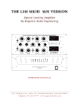
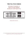
T H E PA L P L U S M K I I I
M i c ro p h o n e P re a m p l i f i e r &
O p t i c a l L e v e lin g A mp lifie r
B y R eq ui site A u d io E n g in e e r in g
OPERATOR’S MANUAL
2 1 7 5 G o o d y e a r Av e , S u i t e 11 0 , Ve n t u r a , C a l i f o r n i a 9 3 0 0 3
t e l e p h o n e : 8 1 8 . 4 3 7 . 0 7 7 9 • w w w. r e q u i s i t e A u d i o . c o m
T H E PA L P L U S M K I I I
TABLE OF CONTENTS
INTRODUCTION
1
RECEIVING YOUR PAL
2
UNPACKING and INSPECTION:
GENERAL NOTES
2
3
WARNING:
3
THIS SHIPMENT SHOULD INCLUDE:
3
SERVICING:
3
ENVIRONMENTAL CONSIDERATIONS:
3
FRONT PANEL CONTROLS (top row)
4
MIC/DI - LINE
4
MIC/DI GAIN
4
MIC/DI GAIN - OPERATIONAL NOTE:
4
HI-PASS FILTER
4
MIC/DI FEEDBACK
4
FRONT PANEL CONTROLS (top row continued)
5
-20dB PAD
5
OUTPUT LEVEL
5
+48V PHANTOM POWER
5
VU METER (upper meter)
5
VU ADJUST (see FRONT PANEL CALIBRATION POINTS)
5
R e q u i s i t e A u d i o E n g i n e e r i n g
PA L P l u s M k I I I
T H E PA L P L U S M K I I I
FRONT PANEL CONTROLS (bottom row)
6
HI-Z INPUT
6
LIMITER RESPONSE
6
LIMITER RESPONSE - OPERATIONAL NOTE:
6
MIC/LINK
6
FRONT PANEL CONTROLS (bottom row continued)
7
MIC/LINK - OPERATIONAL NOTE:
7
LIMITER FEEDBACK
7
LIMITER FEEDBACK - OPERATIONAL NOTE:
7
LIMITER LINK
7
FRONT PANEL CONTROLS (bottom row continued)
8
PEAK REDUCTION
8
PEAK REDUCTION - OPERATIONAL NOTE:
8
RATIO 10:1 / 3:1
8
GR TRK
8
PEAK REDUCTION METER (lower meter)
8
FRONT PANEL CALIBRATION POINTS
9
CALIBRATION POINTS
9
GR TRK - CALIBRATION PROCEDURE:
9
FRONT PANEL CALIBRATION POINTS (continued)
10
VU ADJUST - CALIBRATION PROCEDURE:
10
STEREO ADJUST - CALIBRATION PROCEDURE:
10
FRONT PANEL CALIBRATION POINTS (continued)
R e q u i s i t e A u d i o E n g i n e e r i n g
11
PA L P l u s M k I I I
T H E PA L P L U S M K I I I
STEREO ADJUST - CALIBRATION PROCEDURE (continued):
11
STEREO ADJUST - OPERATIONAL NOTE:
11
FRONT PANEL CALIBRATION POINTS (continued)
12
RESET STEREO ADJUST to higher sensitivity:
12
GR ZERO ADJUST
12
GR ZERO ADJUST - OPERATIONAL NOTE:
12
REAR PANEL (LEFT to RIGHT, top and bottom row)
13
GROUND
13
POWER SUPPLY INLET
13
AUDIO OUTPUTS
13
LIMITER LINK
13
TUBE CHANNEL
13
TUBE PLACEMENT and FUNCTION (left to right)
13
AUDIO INPUTS
13
OUTBOARD POWER SUPPLIES
14
POWER SUPPLIES
14
POWER ON
14
VOLTAGE SELECT
14
FUSE
14
WARRANTY
R e q u i s i t e A u d i o E n g i n e e r i n g
15
PA L P l u s M k I I I
T H E PA L P L U S M K I I I
INTRODUCTION
THANK YOU
Thank you for using the PAL Plus MkIII and thereby making it a part of your art. The PAL Plus
MkIII is the third generation of our PAL platform, now in it’s 13th year of production (2011).
The original PAL (Preamp And Limiter) was introduced in 1998. and was based on a combination of our original Y7 microphone preamplifier and our L1 optical limiter. Within a year, the
PAL was outselling all four versions of the Y7 and L1 combined. For us, this established the
PAL as a permanent platform for continued development and refinement.
After seven years of production (2005), the PAL & PAL Plus evolved to become the PAL Plus
MkIII and represents what a truly modern, multi-function, audio processor can be.
Components and construction are the highest quality seen in the audio industry today. Each
unit is point-to-point hand-wired to solid Teflon terminal strips and oxygen free copper post.
All audio transformers are based on classic designs, upgraded wherever appropriate, and made
to our specifications. High-grade polypropylene capacitors are used exclusively in the signal
path. Polypropylene caps are also used for B+ filtering, making Requisite the only pro audio
products that do not use electrolytic caps for filtering in their main frames. Allen-Bradley carbon composition resistors, gold switches, gold and ceramic tube sockets and special audio wire
are all selected for their tonal character and reliability. This design approach has yielded characteristics that include wide bandwidth, low noise, low distortion, reliability and truly high fidelity performance making the PAL+ MkIII a “must have” for any rack.
The PAL Plus MkIII is available with a choice of two, outboard power supplies. The OPS-2D is
a high-grade, high-capacity solid-state power supply, capable of supplying up to two PAL Plus
MkIII main frames for mono or stereo operation. The RTS-4A is a tube rectified, 4-space, rack
mounted power supply. Filtering is a choke input to oil/poly filter caps and each channel is individually tube regulated. The RTS-4A is expandable from 1 to 4 channels and is designed for
the ultimate in high-fidelity audio performance.
Please read this manual carefully as it contains information essential to the proper operation of
the unit. We welcome your comments and encourage you to write or call.
Thank you again, and please enjoy!
Danny “Sage” McKinney (Founder/President)
Requisite Audio Engineering
[email protected]
818.437.0779
R e q u i s i t e A u d i o E n g i n e e r i n g
L2M MkIII
1
T H E PA L P L U S M K I I I
RECEIVING YOUR PAL
UNPACKING and INSPECTION:
Your shipment has been carefully inspected, checked and packaged at our company before being turned over to the carrier.
We fully expect your PAL to arrive in your hands without having been harmed. However, at the point at which you do receive the product, it becomes your property. Therefore it is important that you carefully inspect the carton and it’s contents for any sign of
physical damage which could have occurred in transit. Record and report any damages
to the transportation company within 24-hours of the original shipment.
Here’s what to do if the shipment has been damaged:
Leave the product, its packing materials and box “as is.” Notify the carrier’s local office
and request an immediate inspection of the shipment.
After said inspection has been made and you have received written notification thereof,
please contact our shop at 818.437.0779 for a return authorization number.
We will repair or replace any damaged merchandise as necessary.
Remember, it is your responsibility to follow the above procedures. Otherwise, the carrier will not honor your damage claim. If you have any questions regarding this notice
or the shipment itself, please notify us immediately.
Thank you,
Requisite Audio Engineering
818.437.0779
R e q u i s i t e A u d i o E n g i n e e r i n g
L2M MkIII
2
T H E PA L P L U S M K I I I
GENERAL NOTES
WARNING:
DO NOT OPEN THE CABINET - RISK OF SEVERE ELECTRICAL SHOCK
THIS SHIPMENT SHOULD INCLUDE:
Model PAL Plus MkIII
Model OPS-2D Solid-State Power Supply or RTS-2A Tube Power Supply
PAL PLUS MkIII Operator’s Manual (this book)
A.C. Cable (if shipped within the USA or Canada)
SERVICING:
The user should not attempt to service this unit beyond that described in this manual.
Internal voltage can exceed 350 VOLTS D.C. !!! Refer all servicing, other than tube and
opto replacement to:
REQUISITE AUDIO ENGINEERING
2175 Goodyear Ave., Suite 110
Ventura, CA 93003
• telephone: 818.437.0779
• email: [email protected]
ENVIRONMENTAL CONSIDERATIONS:
This and all electronic equipment require adequate ventilation and a dry environment
for safe operation and long component life. If proper ventilation from behind the unit is
provided, the PAL mainframe will require 3 rack spaces for mounting. If the RTS-4A
tube supply is also used, it will require an additional 4 rack spaces (7 total). If using the
OPS-2D (solid-state supply), it can be placed at the bottom of the rack, assuming reasonable ventilation.
Do not allow either unit to become overheated.
Also, while circuitry susceptible to hum pick-up is sufficiently shielded from moderate
electromagnetic fields, installation should be planned to avoid mounting the system adjacent to power transformers, motors, etc.
R e q u i s i t e A u d i o E n g i n e e r i n g
L2M MkIII
3
T H E PA L P L U S M K I I I
FRONT PANEL CONTROLS (top row)
MIC/DI - LINE
This switch selects between the transformer balanced microphone input and the transformer
balanced +4 line level input. The associated XLR connectors appear on the rear panel.
MIC/DI GAIN
Provides continuously variable gain of the microphone and direct instrument (DI) inputs. When
used in conjunction with the output level control the input gain can be adjusted to create clean
gain or to slightly overdrive the front end. When LINE input mode is selected, the MIC/DI control has no effect.
MIC/DI GAIN - OPERATIONAL NOTE:
The PAL is designed to give a broad range of textural and tonal possibilities. Setting MIC/DI
GAIN to lower levels with higher levels applied to the OUTPUT LEVEL will result in a cleaner
sound. If the setting is too low, you may not have sufficient level to drive the PEAK REDUCTION. With a little practice, you will get the feel for how best to “dial-in” the ideal sound and
how to balance the interaction of these functions:
• MIC/DI GAIN and MIC/DI FEEDBACK drive the limiter.
• LIMITER RESPONSE and PEAK REDUCTION control the limiter.
• LIMITER FEEDBACK and OUTPUT LEVEL drive the output to recorder/mixer.
HI-PASS FILTER
Reduces rumble. This filter features a gentle slope with maximum reduction at 35Hz and below.
Designed to be as unobtrusive to audio quality as possible. In the LINE input mode the HIPASS switch has no effect.
MIC/DI FEEDBACK
Left to run freely, vacuum tubes tend to exhibit a considerable amount of harmonic generation
and other forms of distortion. For over half a century, negative feedback has been engineered
into circuits to “improve” the linearity of vacuum tubes when used in audio gain stages. However, best readings on a meter don’t always equate to the ideal sound (whatever that happens to
be). By making MIC/DI FEEDBACK an adjustable feature, harmonic content and texture are
put into the hands of the audio engineer and not the guy with the THD meter.
The MIC/DI FEEDBACK control provides continuously variable adjustment of the amount of
negative ‘local’ feedback in the MIC/DI gain stages. Set to ‘0’ the feedback is at the setting of the
original PAL with the maximum amount of feedback being applied. When set fully clockwise,
9dB of feedback is lifted from the stage, allowing the tube (12AY7) to run in its ‘less than linear’
state with a great deal more harmonic content present in the audio. Upper harmonics will have
additional intermodulation distortion. In the Line mode the MIC/DI FEEDBACK control has
no effect.
R e q u i s i t e A u d i o E n g i n e e r i n g
L2M MkIII
4
T H E PA L P L U S M K I I I
FRONT PANEL CONTROLS (top row continued)
-20dB PAD
Applied only to the mic input before the microphone input transformer. If your source volume
is extremely loud and/or you are using a highly sensitive microphone, the -20dB pad may be
necessary to avoid distortion at the input.
OUTPUT LEVEL
MIC/DI INPUT MODE - This control should be adjusted for the desired output level (as indicated on the VU meter) after all other controls have been set.
LINE INPUT MODE - This control should be set for the desired output level (as indicated on the
VU meter) after the LIMITER FEEDBACK, LIMITER RESPONSE and PEAK REDUCTION control have been adjusted. The PAL can provide up to 68dB of gain in the mic mode and up to
30dB of gain in the limiter mode and drive at +26dB before the clipping.
+48V PHANTOM POWER
For operation of microphones requiring +48VDC phantom power. Voltage only appears on MIC
INPUT XLR (pin-2 and pin-3).
VU METER (upper meter)
VU type meter allows for visual monitoring of the output level. Using VU ADJUST, 0dB can be
adjusted for any reference level desired. Before leaving our shop 0dB is set to +10dBu. This
seems to be a practical reference for driving digital recorders. Meter illumination is provided
and also serves as a system pilot light.
VU ADJUST (see FRONT PANEL CALIBRATION POINTS)
Provides continuously variable, user adjustment of the 0dB reference level. VU ADJUST is for
calibration of the VU METER (top meter) only. It does not affect GAIN REDUCTION readings.
R e q u i s i t e A u d i o E n g i n e e r i n g
L2M MkIII
5
T H E PA L P L U S M K I I I
FRONT PANEL CONTROLS (bottom row)
HI-Z INPUT
The ¼” jack accepts single-ended outputs ranging from guitar pick-ups to active outputs from
keyboards and drum machines. It provides a high load impedance of 1.5 meg ohms and will
achieve a gain of 50dB. The MIC/LINE SWITCH must be in the MIC position for the Hi-Z input
to operate. This switching jack will disconnect the XLR MIC input , however, it is recommended practice to unplug any mic cable that may be connected to the Mic Input when using
the HI-Z INPUT.
LIMITER RESPONSE
Essentially, LIMITER RESPONSE is a hi-pass filter to the limiter detection circuit. With this control set to the “0” position the PAL + MkIII will provide approximately equal peak reduction at
all frequencies.
With LIMITER RESPONSE set fully clockwise, frequencies below 1-kHz gradually require more
energy to initiate gain reduction. For frequencies below 100Hz, gain reduction initiation is down
approximately 10dB. This can be very useful in reducing over-activity in program material or
for compressing mid to high frequencies while avoiding typical “pumping” and “breathing”
artifacts in the audio.
LIMITER RESPONSE - OPERATIONAL NOTE:
For uniform limiter initiation and response in MONO or LINK mode, both channels require
LIMITER RESPONSE to be at the same setting. This is also applies to PEAK REDUCTION.
Additional PEAK REDUCTION may be needed to offset the reduction in limiting action that
occurs as you increase the setting of the LIMITER RESPONSE.
MIC/LINK
Unique to the PAL Plus MkIII, this switch allows for inter-connection between two PAL microphone preamplifiers (a second PAL and inter-connect cable is required). Because of where (in
the circuit) the connection is made, the microphone only “sees” one preamp and is loaded as it
would normally be, using just one preamp. Having one mic drive two mic-pres offers many
sonic and stylistic possibilities, especially when one considers the broad range of tonal variation
of the PALs variable gain structure, variable feedback circuitry and limiter functions. Layering
from a pair of PALs is encouraged.
R e q u i s i t e A u d i o E n g i n e e r i n g
L2M MkIII
6
T H E PA L P L U S M K I I I
FRONT PANEL CONTROLS (bottom row continued)
MIC/LINK - OPERATIONAL NOTE:
A useful technique is to set one unit to normal compression levels and the second unit to very
light, if any, compression and record each output to it’s own track. During mixdown, adjust the
normally compressed track to normal levels as the main track and set the lightly or noncompressed track so that it “pokes through” during the heaviest compression of the first track.
This is very effective in creating tracks that always sound big regardless of how dense the background track becomes. Naturally, experimentation is encouraged.
LIMITER FEEDBACK
As used in the PAL Plus MkIII, LIMITER FEEDBACK is similar in concept to the MIC/DI
FEEDBACK circuit except it is “semi-global” (between 12AX7 and 12BH7A) as opposed to “local” (within the 12AY7) as found in the MIC gain stage. Experimentation is encouraged.
LIMITER FEEDBACK - OPERATIONAL NOTE:
A “0” adjustment (counterclockwise) is the most linear and clean setting. Advancing the control
“clockwise” generates a good deal of harmonics and adds complexity to the audio. Use the
OUTPUT LEVEL control to offset the increase in output level as you increase LIMITER FEEDBACK.
With program material, a bell-curve can clearly be heard as feedback is advanced. Turning
“clockwise”, you will hear harmonics and gain being increased and the material become more
exciting. At some point (program and level dependent) you will notice the bass becoming “soft
or a little wooly” and the sound will become less focused. This would be the point where you
have gone beyond the peak of the bell and would be where you may want to slightly reduce
the LIMITER FEEDBACK for tighter bass, yet still have a good deal of increased harmonic content. Naturally, you are encouraged to experiment, there is a lot of personality available once
you being to work with the interactivity of all the controls.
LIMITER LINK
This switch is for whenever two PAL limiters are to be used as a stereo pair. In order for this
switch to be effective, the ¼” link jack found on the rear panel must be interconnected (using
shielded cable) to the same jack on a second PAL limiter (for best results keep the cable length to
a minimum).
This switch links PEAK DETECTION and the PEAK REDUCTION control. All other controls
remain independent. For processing stereo program material, be sure that the RATIO switches,
PEAK REDUCTION , LIMITER RESPONSE and LIMITER FEEDBACK controls of both units
are adjusted to the same setting. This will provide the best possible stereo image with the least
amount of limiting artifacts.
R e q u i s i t e A u d i o E n g i n e e r i n g
L2M MkIII
7
T H E PA L P L U S M K I I I
FRONT PANEL CONTROLS (bottom row continued)
PEAK REDUCTION
With PEAK REDUCTION set fully counter-clockwise, the MIC/DI input and LINE input exhibit
no gain reduction and the PAL acts as a preamplifier or line amplifier. Turning PEAK REDUCTION clockwise will gradually initiate gain reduction for either the MIC/DI or LINE inputs,
depending on which is selected. PEAK REDUCTION should be set for the desired amount of
gain reduction as indicated on the (lower) GR meter. A reading of -3dB to -7dB during the highest peaks of program material is a reasonable range to work within, however, you are encouraged to experiment.
PEAK REDUCTION - OPERATIONAL NOTE:
When using two PALs for stereo gain reduction, it is customary to LINK for processing stereo
material. Keep in mind, the forgiving nature of the optical attenuators found in the PAL allows
for mono operation when processing most stereo material. We encourage experimentation in
this regard.
LINK allows each channel to “see” what the other channel “sees”. LINK does not link parameters. In other words, be sure to adjust the controls of both channels to identical settings. In link
mode, a single PEAK REDUCTION knob can initiate gain reduction in both channels, however,
you will not be able to get balanced LIMITER RESPONSE or RATIO without both channel’s
controls adjusted to the same settings.
RATIO 10:1 / 3:1
The purpose of this switch is to allow selection of either compressor (3:1) or limiter (10:1).
Compression (3:1) occurs from the breakaway point (-30dB input). In the 10:1 position, the PAL
operates as a compressor until it reaches the -20dB point then rolls-over into limiting action.
Thus, combining the characteristics of a compressor and a limiter in the 10:1 mode.
GR TRK
Positioned just above the RATIO switch, the GAIN REDUCTION TRACKING trimmer is used
to adjust the tracking accuracy of the GAIN REDUCTION METER relative to the amount of
GAIN REDUCTION that is occurring in the audio.
PEAK REDUCTION METER (lower meter)
When at rest, the PEAK REDUCTION METER will indicate 0dB (100%) until gain reduction is
initiated, at which time the pointer will move in negative direction to indicate the amount of
gain reduction in dB. When the unit is first turned on, the PEAK REDUCTION METER may
read slightly above or below 0dB. This is a normal condition. After sufficient warm-up time the
meter will rest at the 0dB position. Meter illumination serves as a system pilot light.
R e q u i s i t e A u d i o E n g i n e e r i n g
L2M MkIII
8
T H E PA L P L U S M K I I I
FRONT PANEL CALIBRATION POINTS
CALIBRATION POINTS
The PAL Plus MkIII has four points of calibration, all of which are found on the front panel.
They are:
• GR TRK - Gain Reduction Tracking is to synchronize the GR meter with the VU meter.
• VU ADJUST - Calibrated for the VU meter (top) in dBu. Factory is 0dB = +10dBu.
• STEREO ADJUST - Balance for stereo operation (2 units) and Peak Reduction sensitivity.
• GR ZERO ADJUST - Gain Reduction meter adjustment to 0dBu (100%) at rest.
Before attempting calibration of any of these parameters, please be sure you fully understand
each step of the process and have the necessary equipment to complete and verify the process.
GR TRK - CALIBRATION PROCEDURE:
The GR TRACK trimmer is used to adjust the tracking accuracy of the GR METER relative to the
amount of GAIN REDUCTION that is occurring in the audio.
• Determine that GR ZERO ADJUST has been made (see GR ZERO ADJUST - CALIBRATION
PROCEDURE).
• Allow 10 minutes of system warm-up time and 1 minute rest from peak reduction activity.
• Set PEAK REDUCTION & LIMITER RESPONSE fully-counterclockwise.
• Set OUTPUT LEVEL, LIMITER FEEDBACK fully-counterclockwise.
• Set RATIO to 3:1
• Inject a +10dB 1-kHz tone (2.45V). Verify level using an external DMM or suitable meter.
• Increase OUTPUT LEVEL until the VU METER (top) reads 0dB.
• Increase PEAK REDUCTION until the VU METER drops to -4dB.
• The GR METER (lower meter) should now show -5dB. If not, use the GR TRK trimmer to adjust it until it reads -5dB. The additional 1dB is to compensate for meter ballistics of 300 milliseconds.
• After adjusting GR TRK, turn off the 1-kHz tone and allow a 2-5 minute period of rest to verify that the needle returns to 100% or 0dB.
• Since GR ZERO ADJUST and GR TRK are interactive, it may be necessary to repeat this process (from step 6) a few times, readjusting GR ZERO ADJUST and GR TRK.
R e q u i s i t e A u d i o E n g i n e e r i n g
L2M MkIII
9
T H E PA L P L U S M K I I I
FRONT PANEL CALIBRATION POINTS (continued)
VU ADJUST - CALIBRATION PROCEDURE:
VU ADJUST is calibrated in dBu. The trimmer has a wide enough range that “0” can be calibrated to virtually any reference level. Factory setting is 0dB = +10dBu (2.45VAC).
• Set PEAK REDUCTION & LIMITER RESPONSE fully-counterclockwise.
• Set OUTPUT LEVEL, LIMITER FEEDBACK fully-counterclockwise.
• Allow 10 minutes system warm-up time and 1 minute rest from any peak reduction activity.
• Adjust your tone generator to a 1kHz sine-wave @ +10dBu (2.45V). Verify level using an external DMM or suitable meter. If your DMM has a dB function, select that. If not, set to A/C
and read 2.45VAC.
• Inject the sine-wave at the LINE input XLR and be sure to select LINE on the front panel.
• Raise the OUTPUT LEVEL control until the external DMM is reading+10dBu and observe if
the VU METER reads 0dB across pins 2&3 of the OUTPUT XLR.
• If not, adjust as necessary.
STEREO ADJUST - CALIBRATION PROCEDURE:
Located between VU ADJUST & GR ZERO ADJUST.
STEREO ADJUST is used to maintain proper stereo imaging during gain reduction, when using
two PAL Plus MkIII units. Please read the calibration procedure carefully and be sure you have
a thorough understanding before attempting this calibration.
• Verify that ZERO ADJ, GR TRACK and VU ADJ are all calibrated. If not, follow the CALIBRATION PROCEDURE instructions for getting each of them to read accurately.
• Set PEAK REDUCTION & LIMITER RESPONSE fully-counterclockwise.
• Set OUTPUT LEVEL, LIMITER FEEDBACK fully-counterclockwise.
• Set RATIO to 3:1.
• Adjust your tone generator to a 1kHz sine-wave @ +10dBu (2.45V). Verify level using an external DMM or suitable meter. If your DMM has a dB function, select that. If not, set to A/C
and read 2.45VAC.
R e q u i s i t e A u d i o E n g i n e e r i n g
L2M MkIII
10
T H E PA L P L U S M K I I I
FRONT PANEL CALIBRATION POINTS (continued)
STEREO ADJUST - CALIBRATION PROCEDURE (continued):
• Inject the +10dB 1-kHz tone to the LINE INPUT. Verify level using an external DMM or suitable meter. If your DMM has a dB function, select that. If not, set to A/C and read 2.45VAC
across pins 2&3 of the OUTPUT XLR.
• Adjust the OUTPUT LEVEL control until the VU METER (top meter) reads 0dB on both units.
• Select LINK.
• Increase PEAK REDUCTION (both channels equally) until the VU METER drops to -4dB on
both channels.
• Observe if both GR meters read -5dBu. The additional 1dB is to compensate for meter ballistics.
• If one meter reads higher than the other, lower it using the STEREO ADJUST trimmer, on the
front panel. As you bring it down, the other meter may start to come up. Stop at the point
where both channels show equal gain reduction.
ONCE THEPREVIOUS STEPS HAVEBEEN TAKEN, YOU CAN “FINE TUNE” YOUR ADJUSTMENT WITH PROGRAM SPECIFIC CALIBRATION IN THE FOLLOWING WAY:
• Find the portion of program material with the highest peaks and create a 5 to 10 second loop.
• If your using LIMITER RESPONSE leave that set to the way you want to hear it.
• Observe which channel is exhibiting the most gain reduction and slowly bring it down until
the two channels match.
STEREO ADJUST - OPERATIONAL NOTE:
Overtime, (perhaps many years) it will become evident that STEREO ADJ will need to be reset
to a higher overall level. The sysmptom will be that PEAK REDUCTION needs to be set to it’s
fully-clockwise position to initiate suficient gain reduction for source material that has a good
deal of level.
R e q u i s i t e A u d i o E n g i n e e r i n g
L2M MkIII
11
T H E PA L P L U S M K I I I
FRONT PANEL CALIBRATION POINTS (continued)
RESET STEREO ADJUST to higher sensitivity:
• Inject a +10dB 1-kHz tone (both channels). Verify level using an external DMM or suitable meter. If your DMM has a dB function, select that. If not, set to A/C and read 2.45VAC across
pins 2&3 of the OUTPUT XLR.
• Select GR on the METER SELECT and observe that both VU METERs read 0dB.
• Select MONO on PK REDUCTION (meter mode select).
• Set PEAK REDUCTION (both channels) to the 12 o’clock position.
• Raise the STEREO ADJ trimmer on each channel until the pointer on the VU meter stops
dropping. This will indicate the level is back to it’s highest setting.
• Once this is done, refer to the STEREO ADJUST - CALIBRATION PROCEDURE (see above)
and re-calibrate STEREO ADJ.
If the above procedure was ineffective in recovering sufficient sensitivity, this could be an indication that the 12AX7 (2ea) and 6AQ5 (2ea) tubes (rear panel, left of optos) have exceeded their
useful lives and replacement is required. This could be the case for only one channel, however,
it would be good practice to change the tubes for both channels, at this time.
GR ZERO ADJUST
The GR ZERO ADJUST trimmer is used to calibrate the Peak Reduction Meter. At rest, the meter should read 100% or 0dB (during periods of no gain reduction).
GR ZERO ADJUST - OPERATIONAL NOTE:
Before determining that adjustments are necessary, be sure to allow 10 minutes of system warmup time and at least 5 minutes rest from any peak reduction activity.
R e q u i s i t e A u d i o E n g i n e e r i n g
L2M MkIII
12
T H E PA L P L U S M K I I I
REAR PANEL (LEFT to RIGHT, top and bottom row)
GROUND
Banana Plug connection to CHASSIS Ground and/or CIRCUIT Ground is provided. Need for
connection is unlikely, but can be useful in eliminating or finding source of hum, should hum
exist.
POWER SUPPLY INLET
For connect to either of the REQUISITE OUTBOARD POWER SUPPLIES, models OPS-2 (SolidState Supply) or RTS-4 (All Tube Supply). When not connected to a power supply, be sure to
use the security cap. The cap will protect the pins from accidental damage. Avoid contact with
the pins, as power supply caps can store voltage and possibly discharge when touched.
AUDIO OUTPUTS
Transformer balanced output.
Pin-1 no connection, Pin 2 positive going phase, Pin-3 negative going phase.
LIMITER LINK
Top for Channel-1, Bottom for Channel-2. Both become linked to each other when PK REDUCTION mode switch is set to LINK.
TUBE CHANNEL
Protective housing for tubes and opto attenuator. When installing your L2M, be sure sufficient
air space is provided to prevent excessive heat build-up from the tubes.
TUBE PLACEMENT and FUNCTION (left to right)
• 6AQ5A or 6005 - LIMITER Supplies voltage to the Electro-Luminescent Panel (T4C)
• 12AX7 - LIMITER Control Voltage Amplifier (Limiter)
• T4C - LIMITER Optolux Electro-Optical Attenuator
• 12BH7A or 12AU7 - AUDIO Cathode Follower/output driver
• 12AX7 - AUDIO Limiter input gain stage
• MIC LINK - AUDIO, RCA (use shielded cable)
• 12AY7 - AUDIO Microphone/DI input gain stage
AUDIO INPUTS
Transformer balanced inputs.
Microphone Level (top)
Pin-1 Ground, Pin-2 positive going phase, Pin-3 negative going phase.
Line Level (bottom).
Pin-1 no connection, Pin-2 positive going phase, Pin-3 negative going phase.
R e q u i s i t e A u d i o E n g i n e e r i n g
L2M MkIII
13
T H E PA L P L U S M K I I I
OUTBOARD POWER SUPPLIES
POWER SUPPLIES
For the PAL Plus MkIII, and all Requisite mainframe audio processors, there is a choice of two
different power supplies:
• OPS-2D solid-state supply (1 to 2 channels)
• RTS-4A all-tube supply (1 to 4 channels)
Each supply is configured for the number of channels required for use a specific mainframe(s).
Depending on the configuration, there will be a cable(s) with a single, multi-pin connector for
B+, Heaters, Meter Lights and phantom power, which brings power to the mainframe unit(s).
POWER ON
This switch is located at the outboard power supply. When first connecting the power supply to
a PAL unit, please be sure your main power switch is turned off. Once the connector is seated,
carefully thread the ring lock of the cable to the jack on the PAL mainframe. If powering only
one PAL+ unit, with a supply having two cables, be sure the unused cable is rolled-up and fastened to the supply with a cover over the unused end.
POWER CABLE
Each supply has an IEC connector for mains A/C. In the U.S. and Canada, the supply is
shipped with a North America power cable. For other countries a power cable is not supplied
and must be purchased locally.
VOLTAGE SELECT
Each power supply has a VOLTAGE SELECT to allow operation with A/C mains of 120V or
240V.
FUSE
Each power supply has a replaceable FUSE for overcurrent protection. Be sure to use the SloBlo type (1.25”/32mm long) at the rating indicated on the supply for the mains voltage being
used. When going from 120V to 240V be sure to reduce the fuse to 1/2 the AMP value of the
120V fuse. Otherwise, the fuse will be overrated and not offer the same level of protection.
R e q u i s i t e A u d i o E n g i n e e r i n g
L2M MkIII
14
T H E PA L P L U S M K I I I
WARRANTY
For a period of 2 years after original purchase, Requisite Audio Engineering will, free of
charge, repair this product if it fails due to defective materials or workmanship. This
limited warranty is subject to the following limitations:
• Units that are discovered to have been opened or tampered with will not be covered
by this warranty. We strongly discourage opening the chassis due to the risk of severe
electrical shock!
• Defects that are, in the sole judgement of Requisite Audio Engineering, the result of
accident, misuse, abuse, neglect, mishandling, misapplication, faulty installation, unauthorized repair, modification, or act of God will not be covered by this warranty.
• In the absence of receipt of original purchase, this warranty is valid for 2 years from
date of manufacture as determined from the units serial number and the records of
Requisite Audio Engineering.
• There are no expressed warranties except as listed above.
• TUBES, OPTOS and LIGHT BULBS are not covered by this warranty, but receive a 90day warranty.
• REQUISITE AUDIO SHALL NOT BE LIABLE FOR PROPERTY DAMAGE OR ANY
OTHER INCIDENTAL OR CONSEQUENTIAL DAMAGE WHATSOEVER WHICH
MAY RESULT FROM THE FAILURE OF THIS PRODUCT OR ARISING OUT OF THE
BREACH OF THIS WARRANTY. Any and all warranties of merchantability and fitness implied by law are limited to the duration of the expressed warranty.
If a problem develops with this product DO NOT OPEN THE UNIT or attempt repairing it yourself. Opening this unit invalidates your warranty and will expose you to risk
of very severe electrical shock!
REFER ALL REPAIR TO REQUISITE AUDIO. Do not return the unit without authorization and instructions from us. Units must be shipped PRE-PAID both directions.
REQUISITE AUDIO cannot be responsible for damage due to shipping or improper
packaging. Save the original packaging.
This warranty gives you specific legal rights and you may also have other rights which
vary from state to state.
R e q u i s i t e A u d i o E n g i n e e r i n g
L2M MkIII
15