1
OPERATION
MANUAL
64-Voice Tone Wheel Organ
B-3
Operation Manual
© 2000 E-MU Systems
All Rights Reserved
Getting Started PN: FI10666
Rev. B
CD PN: CD10562 Rev. B
E-MU World Headquarters
E-MU Systems U.S.A.
P.O. Box 660015
Scotts Valley, CA USA
95067-0015
Telephone: 831-438-1921
Fax: 831-438-8612
Internet: www.emu.com
Europe, Africa, Middle East
E-MU Systems, Ltd.
Suite 6, Adam Ferguson House
Eskmills Industrial Park
Musselburgh, East Lothian
Scotland, EH21 7PQ
Tel: +44 (0) 131-653-6556
Fax: +44 (0) 131-665-0473
Important Notice:
In order to obtain warranty service on your B-3 unit, the serial number sticker must be intact and you must
have a sales receipt or other proof of purchase. If there is no serial number sticker on the B-3, please contact
E-MU Systems at once.
This product is covered under one or more of the following U.S. patents: 4,404,529; 4,506,579; 4,699,038;
4,987,600; 5,013,105; 5,072,645; 5,111,727; 5,144,676; 5,170,367; 5,248,845; 5,303,309; 5,317,104;
5,342,990; 5,430,244 and foreign patents and/or pending patents. B-3 is a registered trademarks of E-MU
Systems. All other trademarks belong to their respective companies.
Introduction
1
Product Description . . . . . . . . . . . . . . . . . . . .1
Overview . . . . . . . . . . . . . . . . . . . . . . . . . . . .2
Important Safety Instructions
3
Grounding Instructions . . . . . . . . . . . . . . . . . .3
Danger! . . . . . . . . . . . . . . . . . . . . . . . . . . . . .3
Caution! . . . . . . . . . . . . . . . . . . . . . . . . . . . . .3
User Maintenance Instructions . . . . . . . . . . . .4
Radio and Television Interference . . . . . . . . . .5
Warnings - German
6
Wichtige Sicherheitsvorschriften . . . . . . . . . . .6
Erdungsinstruktionen . . . . . . . . . . . . . . . . . . .6
Gefahr . . . . . . . . . . . . . . . . . . . . . . . . . . . . . .6
Vorsicht. . . . . . . . . . . . . . . . . . . . . . . . . . . . . .6
Unterhaltsinstruktionen für anwender . . . . . . .7
Vorsicht. . . . . . . . . . . . . . . . . . . . . . . . . . . . . .7
Warnings - French
9
Instructions de Sécurité Importantes . . . . . . . .9
Instructions de Mise à la Terre . . . . . . . . . . . . .9
Danger . . . . . . . . . . . . . . . . . . . . . . . . . . . . . .9
Attention . . . . . . . . . . . . . . . . . . . . . . . . . . . .9
Instructions de
Maintenance. . . . . . . . . . . . . . . . . . . . . . . . . .9
Interférences Radio et Télévision . . . . . . . . . . .11
Declaration of Conformity
12
Setup
13
Unpacking . . . . . . . . . . . . . . . . . . . . . . . . . . .13
Connection Instructions . . . . . . . . . . . . . . . . .14
Basic Setup . . . . . . . . . . . . . . . . . . . . . . . . . . . . 14
Studio Setup . . . . . . . . . . . . . . . . . . . . . . . . . . 15
Power Up! . . . . . . . . . . . . . . . . . . . . . . . . . . . . 16
Instant Gratification . . . . . . . . . . . . . . . . . . . .17
Playing Demo Sequences . . . . . . . . . . . . . . . . .
Auditioning Presets . . . . . . . . . . . . . . . . . . . . . .
Selecting and Quick Editing Presets . . . . . . . . .
Bank Select Commands . . . . . . . . . . . . . . . . . .
3 E-MU Systems
17
17
18
20
Basic Operations
21
Front Panel . . . . . . . . . . . . . . . . . . . . . . . . . . .21
Volume Control . . . . . . . . . . . . . . . . . . . . . . . .
Master Button . . . . . . . . . . . . . . . . . . . . . . . . .
Edit Button . . . . . . . . . . . . . . . . . . . . . . . . . . . .
Control Button . . . . . . . . . . . . . . . . . . . . . . . . .
Audition Button . . . . . . . . . . . . . . . . . . . . . . . .
Left/Right Cursor Buttons . . . . . . . . . . . . . . . . .
Multisetup Button . . . . . . . . . . . . . . . . . . . . . .
Save/Copy Button . . . . . . . . . . . . . . . . . . . . . .
Home/Enter Button . . . . . . . . . . . . . . . . . . . . .
Data Entry Control . . . . . . . . . . . . . . . . . . . . . .
Controller Knobs . . . . . . . . . . . . . . . . . . . . . . .
21
21
21
21
22
22
22
22
23
23
23
Front Panel Controller Modes . . . . . . . . . . . . .23
Real-time Control . . . . . . . . . . . . . . . . . . . . . . . 23
Quick Edit . . . . . . . . . . . . . . . . . . . . . . . . . . . . 24
Deep Edit Mode . . . . . . . . . . . . . . . . . . . . . . . . 25
Main Screen . . . . . . . . . . . . . . . . . . . . . . . . . .26
MIDI Channel Selection . . . . . . . . . . . . . . . . . .
Preset Selection . . . . . . . . . . . . . . . . . . . . . . . .
Channel Volume . . . . . . . . . . . . . . . . . . . . . . . .
Channel Pan . . . . . . . . . . . . . . . . . . . . . . . . . . .
26
26
27
28
Sound Navigator. . . . . . . . . . . . . . . . . . . . . . .29
Preset Category . . . . . . . . . . . . . . . . . . . . . . . . 29
Instrument Category . . . . . . . . . . . . . . . . . . . . 29
Multitimbral Operation . . . . . . . . . . . . . . . . . .30
Multisetup
31
Multisetups . . . . . . . . . . . . . . . . . . . . . . . . . . .31
Restoring Multisetups . . . . . . . . . . . . . . . . . . . . 32
Multitimbral Sequencing. . . . . . . . . . . . . . . . .34
Master Menu
35
Defining Master Parameters . . . . . . . . . . . . . .36
Transpose/Tune . . . . . . . . . . . . . . . . . . . . . . . .
Bend Range . . . . . . . . . . . . . . . . . . . . . . . . . . .
Velocity Curve . . . . . . . . . . . . . . . . . . . . . . . . .
Mix Output . . . . . . . . . . . . . . . . . . . . . . . . . . .
36
36
37
37
Master Effects . . . . . . . . . . . . . . . . . . . . . . . . .39
Effects Mode . . . . . . . . . . . . . . . . . . . . . . . . . . 39
Effects Multi Mode Control . . . . . . . . . . . . . . . . 39
Master FXA Algorithm . . . . . . . . . . . . . . . . . . . 40
FXA Parameters: Decay/HF Damping FxB -> FxA 41
FXA Send Amounts . . . . . . . . . . . . . . . . . . . . . . 41
Master FXB Algorithm . . . . . . . . . . . . . . . . . . . 41
FXB Parameters: Feedback/LFO Rate Delay Time 42
FXB Send Amounts . . . . . . . . . . . . . . . . . . . . . . 42
4 E-MU Systems
MIDI Parameters . . . . . . . . . . . . . . . . . . . . . . 43
MIDI Mode . . . . . . . . . . . . . . . . . . . . . . . . . . .
MIDI SysEx ID . . . . . . . . . . . . . . . . . . . . . . . . .
MIDI Enable . . . . . . . . . . . . . . . . . . . . . . . . . . .
MIDI Program Change -> Preset . . . . . . . . . . . .
Receive Program Change . . . . . . . . . . . . . . . . .
Real-time Controller Assignment . . . . . . . . . . .
MIDI Footswitch Assign . . . . . . . . . . . . . . . . . .
Tempo Controller . . . . . . . . . . . . . . . . . . . . . .
Knob Preset Quick-Edit . . . . . . . . . . . . . . . . . . .
Knobs Deep Edit . . . . . . . . . . . . . . . . . . . . . . .
Knobs/Riff MIDI Out . . . . . . . . . . . . . . . . . . . . .
Preset Edit All Layers Enable . . . . . . . . . . . . . . .
Front Panel Knob Calibration . . . . . . . . . . . . . .
MIDI SysEx Packet Delay . . . . . . . . . . . . . . . . .
Send MIDI System Exclusive Data . . . . . . . . . . .
User Key Tuning . . . . . . . . . . . . . . . . . . . . . . . .
Base Tempo . . . . . . . . . . . . . . . . . . . . . . . . . . .
Screen Viewing Angle . . . . . . . . . . . . . . . . . . .
Programming Basics
43
43
44
44
45
45
46
47
47
48
48
48
49
50
50
51
52
52
53
Modulation . . . . . . . . . . . . . . . . . . . . . . . . . . 54
Modulation Sources . . . . . . . . . . . . . . . . . . . 55
Random Sources . . . . . . . . . . . . . . . . . . . . . . . 56
Modulation PatchCords. . . . . . . . . . . . . . . . .
Envelope Generators . . . . . . . . . . . . . . . . . . .
Low Frequency Oscillators (LFOs) . . . . . . . . .
Clock Modulation . . . . . . . . . . . . . . . . . . . . .
Modulation Destinations . . . . . . . . . . . . . . . .
Modulation Processors . . . . . . . . . . . . . . . . .
Preset Modulation Processors . . . . . . . . . . . .
56
57
59
60
62
63
65
Using the Modulation Processors . . . . . . . . . . . 67
More Examples . . . . . . . . . . . . . . . . . . . . . . . . 69
Dynamic Filters . . . . . . . . . . . . . . . . . . . . . . . 71
What is a Filter? . . . . . . . . . . . . . . . . . . . . . . . . 72
Parametric Filters . . . . . . . . . . . . . . . . . . . . . . . 75
The Z-Plane Filter . . . . . . . . . . . . . . . . . . . . . . . 76
Signal Flow . . . . . . . . . . . . . . . . . . . . . . . . . . 77
MIDI Channels & Real-time Controls . . . . . . . 78
Bank Select Commands . . . . . . . . . . . . . . . . . . 80
Stereo Mix Outputs. . . . . . . . . . . . . . . . . . . . 81
Edit Menu
83
Preset Name . . . . . . . . . . . . . . . . . . . . . . . . . . 84
Four Layer Architecture . . . . . . . . . . . . . . . . . 85
B-3 Operation Manual 5
Selecting Layers . . . . . . . . . . . . . . . . . . . . . . . . 85
Defining Layer Parameters . . . . . . . . . . . . . . .86
Selecting an Instrument . . . . . . . . . . . . . . . . . .
Defining Key Range . . . . . . . . . . . . . . . . . . . . .
Defining the Velocity Crossfade Range . . . . . . .
Defining the Real-time Crossfade Range . . . . . .
Transposing the Instrument . . . . . . . . . . . . . . .
Tuning . . . . . . . . . . . . . . . . . . . . . . . . . . . . . . .
Amplifier . . . . . . . . . . . . . . . . . . . . . . . . . . . . .
Volume Envelope . . . . . . . . . . . . . . . . . . . . . . .
Chorusing the Layer . . . . . . . . . . . . . . . . . . . . .
Sound Start Offset and Delay . . . . . . . . . . . . . .
Non-Transpose Mode . . . . . . . . . . . . . . . . . . . .
Solo Mode . . . . . . . . . . . . . . . . . . . . . . . . . . . .
Assign Group . . . . . . . . . . . . . . . . . . . . . . . . . .
Glide . . . . . . . . . . . . . . . . . . . . . . . . . . . . . . . .
Z-Plane Filters . . . . . . . . . . . . . . . . . . . . . . . . . .
Filter Envelope . . . . . . . . . . . . . . . . . . . . . . . . .
Auxiliary Envelope . . . . . . . . . . . . . . . . . . . . . .
Low Frequency Oscillators (LFOs) . . . . . . . . . . .
PatchCords . . . . . . . . . . . . . . . . . . . . . . . . . . . .
Pitch Bend Range . . . . . . . . . . . . . . . . . . . . . . .
Mix Output . . . . . . . . . . . . . . . . . . . . . . . . . . .
86
87
90
92
95
96
96
97
99
99
100
100
101
102
103
106
108
108
113
116
116
Common Preset Parameters . . . . . . . . . . . . . .117
Preset Effects . . . . . . . . . . . . . . . . . . . . . . . . . .
FXA Algorithm . . . . . . . . . . . . . . . . . . . . . . . . .
FXA Parameters . . . . . . . . . . . . . . . . . . . . . . . .
FXA Send Amounts . . . . . . . . . . . . . . . . . . . . . .
FXB Algorithm . . . . . . . . . . . . . . . . . . . . . . . . .
FXB Parameters . . . . . . . . . . . . . . . . . . . . . . . .
FXB Send Amounts . . . . . . . . . . . . . . . . . . . . . .
Preset Patchcords . . . . . . . . . . . . . . . . . . . . . . .
Initial Controller Amount . . . . . . . . . . . . . . . . .
Keyboard Tuning . . . . . . . . . . . . . . . . . . . . . . .
Preset Links . . . . . . . . . . . . . . . . . . . . . . . . . . .
Preset Tempo Offset . . . . . . . . . . . . . . . . . . . . .
Audition Riff Selection . . . . . . . . . . . . . . . . . . .
Play Solo Layers . . . . . . . . . . . . . . . . . . . . . . . .
Programming Tutorial
117
119
120
120
120
121
121
121
123
124
126
127
127
127
129
Editing Presets . . . . . . . . . . . . . . . . . . . . . . . .129
Changing the Instrument . . . . . . . . . . . . . . . . .
Changing the Tuning of an Instrument . . . . . .
Chorus . . . . . . . . . . . . . . . . . . . . . . . . . . . . . . .
Volume Envelope . . . . . . . . . . . . . . . . . . . . . . .
Working with Filters . . . . . . . . . . . . . . . . . . . . .
Practice Modulating . . . . . . . . . . . . . . . . . . . . .
Troubleshooting . . . . . . . . . . . . . . . . . . . . . . . .
129
130
131
131
133
137
138
Linking Presets . . . . . . . . . . . . . . . . . . . . . . . .139
6 E-MU Systems
Effects 141
Effects Overview . . . . . . . . . . . . . . . . . . . . . . 141
The Effects Sends . . . . . . . . . . . . . . . . . . . . . . . 141
Effect Types. . . . . . . . . . . . . . . . . . . . . . . . . . 143
Effect Parameters . . . . . . . . . . . . . . . . . . . . . . . 143
Effects Programmed in the Preset . . . . . . . . . 145
Master Effects . . . . . . . . . . . . . . . . . . . . . . . . 146
Effects Mode . . . . . . . . . . . . . . . . . . . . . . . . . . 148
Flexible Effects Control . . . . . . . . . . . . . . . . . . . 148
Effect B Into Effect A . . . . . . . . . . . . . . . . . . . . . 150
General Effect Descriptions . . . . . . . . . . . . . . 152
Reverb . . . . . . . . . . . . . . . . . . . . . . . . . . . . . . .
Chorus . . . . . . . . . . . . . . . . . . . . . . . . . . . . . . .
Doubling . . . . . . . . . . . . . . . . . . . . . . . . . . . . .
Slapback . . . . . . . . . . . . . . . . . . . . . . . . . . . . .
Stereo Flanger . . . . . . . . . . . . . . . . . . . . . . . . .
Delay . . . . . . . . . . . . . . . . . . . . . . . . . . . . . . . .
Stereo Delay . . . . . . . . . . . . . . . . . . . . . . . . . .
Panning Delay . . . . . . . . . . . . . . . . . . . . . . . . .
Dual Tap . . . . . . . . . . . . . . . . . . . . . . . . . . . . .
Vibrato . . . . . . . . . . . . . . . . . . . . . . . . . . . . . . .
Distortion . . . . . . . . . . . . . . . . . . . . . . . . . . . . .
Save/Copy Menu
152
153
153
153
153
154
154
154
154
154
154
155
Saving a Preset . . . . . . . . . . . . . . . . . . . . . . . 155
Copying Information. . . . . . . . . . . . . . . . . . . 156
Copy Preset . . . . . . . . . . . . . . . . . . . . . . . . . . .
Copy Layer . . . . . . . . . . . . . . . . . . . . . . . . . . . .
Copy PatchCords . . . . . . . . . . . . . . . . . . . . . . .
Copy Preset Bank . . . . . . . . . . . . . . . . . . . . . . .
Create Random Preset . . . . . . . . . . . . . . . . . . .
Copy User Bank to Flash . . . . . . . . . . . . . . . . . .
Rename Flash SIMM . . . . . . . . . . . . . . . . . . . . .
Duplicate Flash . . . . . . . . . . . . . . . . . . . . . . . . .
Appendix
156
156
157
158
158
159
160
161
163
Front Panel Knob Functions. . . . . . . . . . . . . . 163
Presets . . . . . . . . . . . . . . . . . . . . . . . . . . . . . 164
B-3 Preset Nomenclature 164
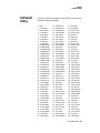
Preset Listing. . . . . . . . . . . . . . . . . . . . . . . . . 165
Preset Listing . . . . . . . . . . . . . . . . . . . . . . . . . . 166
Preset Listing . . . . . . . . . . . . . . . . . . . . . . . . . . 167
B-3 Preset Suffixes . . . . . . . . . . . . . . . . . . . . . . 168
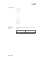
Riff Listing . . . . . . . . . . . . . . . . . . . . . . . . . . . 168
Instrument Listing . . . . . . . . . . . . . . . . . . . . . 169
Instrument Listing . . . . . . . . . . . . . . . . . . . . . . . 170
B-3 Operation Manual 7
B-3 Instrument Suffixes . . . . . . . . . . . . . . . . . . 170
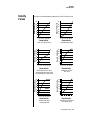
Velocity Curves . . . . . . . . . . . . . . . . . . . . . . . .171
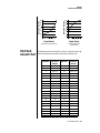
PatchCord Amount Chart . . . . . . . . . . . . . . . .173
MIDI . . . . . . . . . . . . . . . . . . . . . . . . . . . . . . . .174
Received Channel Commands . . . . . . . . . . . . . 176
SysEx Specification . . . . . . . . . . . . . . . . . . . . . . 176
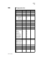
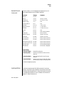
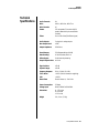
Technical Specifications. . . . . . . . . . . . . . . . . .177
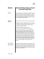
Warranty. . . . . . . . . . . . . . . . . . . . . . . . . . . . .178
Warranty . . . . . . . . . . . . . . . . . . . . . . . . . . . . .
Warranty Restrictions . . . . . . . . . . . . . . . . . . . .
How To Obtain Warranty Service . . . . . . . . . . .
Personnel . . . . . . . . . . . . . . . . . . . . . . . . . . . . .
Equipment . . . . . . . . . . . . . . . . . . . . . . . . . . . .
Recording . . . . . . . . . . . . . . . . . . . . . . . . . . . . .
Index
8 E-MU Systems
178
178
178
179
179
179
181
Introduction
Congratulations on your purchase of the E-MU B-3 - 64 voice tone wheel
organ sound module. This custom module was carefully engineered to
capture the sound and feel of the original legendary B-3. The rotating
speaker effects can be spun-up and spun-down independent of note-on
events and a single trigger, polyphonic harmonic percussion generator
perfectly simulates the playing behavior of the original. Meticulous
sampling and advanced synthesis technology combine to provide a perfect
recreation of the original instrument.
Product
Description
B-3 contains two user-upgradable sound SIMM sockets, allowing you to mix
and match sound sets according to your needs. New sounds can be added as
easily as plugging in a new 16MB or 32MB SIMM module. Each E-MU
sound set has been painstakingly crafted to be the best of its kind. Samples
are matched across the keyboard, perfectly looped, and rich in harmonic
texture.
B-3 has enough memory for 512 user presets and can hold literally
thousands of factory presets. (ROM presets are automatically added when
sound SIMMs are installed. As an example, a 32 MB SIMM may contain up to
1024 ROM presets.) B-3’s Sound Navigator is a major improvement to the
main screen that makes it easy to find the exact sound you want. It’s
powerful, yet simple to use.
The real power and value of B-3 becomes apparent when you want to
customize your own sounds. The extremely flexible yet easy to use, 4-layer
synthesizer voices make it easy to build sounds of any kind. Layers can be
switched or crossfaded using key position, velocity, real-time controllers or
any modulation source. B-3 also contains 50 different 6th and 12th order
resonant & modeling filters which are used to shape and modify the raw
samples.
The 64 modulation sources include three multistage envelopes and two
LFOs per layer, as well as full MIDI control over virtually every parameter.
The digital patch bay, with 24 cords per layer, (and 12 more cords per
preset) lets you connect modulation sources to 64 destinations in any
imaginable way.
B-3 Operation Manual 1
Introduction
Overview
The patch bay also contains a set of arithmetic modifiers, letting you create
complex synthesis models.
Four front panel real-time controllers give you control over 12 userselectable parameters. The real-time knobs can adjust multiple parameters
at once, allowing complex levels of control. For example, one knob can
simultaneously turn up filter cutoff, while detuning one sample, and
adjusting the release time of the volume envelope. Virtually every synth
parameter in the B-3 is controllable using the real-time knobs or by any
internal or external control source.
Two 18-bit analog outputs and four internal effect sends let you process
separate sounds inside B-3 and output a complex mix controlled by MIDI or
internal sources.
Once you have created your preset, you can add richness to your sound
using B-3’s 24-bit stereo effects. You can choose a different effects setup for
each preset from over 60 algorithms. B-3’s effects section is actually two
separate effects processors with control over each wet/dry mix level on four
effects sends. Effects Processor “A” contains primarily ambiance algorithms
like reverb and delays, while effects processor “B” contains primarily
spectral algorithms such as chorus, flange, phase, distortion, and delay.
Effects can be linked to each preset or used globally to further enhance your
sound.
Other features include multiple solo, voice assignment and performance
modes for expressive control, 12 user-definable alternate tunings, an
extremely easy to use interface and, of course, an extensive MIDI
implementation.
Overview
This is the Getting Started manual for setting up and playing B-3, which
contains only the first four chapters of the complete manual. This short
manual is intended to give you the basics of playing and controlling B-3.
To get the most out of this extremely powerful instrument please refer to
the complete B-3 manual, which is provided for you in PDF format (PC and
Mac formats) on the supplied CD-ROM.
The manual provides step-by-step instructions for all of B-3’s features. Each
parameter is described in detail, with examples where deemed appropriate.
Although a short synthesizer/synthesis tutorial is provided, you may
require more information than this manual provides. Many excellent books
and periodicals have been published on the subject of music synthesis.
There are is also a large amount of information available via the www.
The appendix provides technical information, product specifications and
the Index.
2 E-MU Systems
Important Safety
Instructions
Use in countries other than the U.S.A. may require the use of a different
line cord or attachment plug, or both. To reduce the risk of fire or electric
shock, refer all servicing to qualified service personnel. Do not expose this
product to rain or moisture. There are no user serviceable parts or adjustments inside the unit.
Grounding
Instructions
Danger!
Caution!
This product must be grounded. If it should malfunction or break down,
grounding provides a path of least resistance for electric current, reducing
the risk of electric shock. This product is equipped with a cord having an
equipment-grounding conductor and a grounding plug. The plug must be
plugged into an appropriate outlet properly installed and grounded in
accordance with all local codes and ordinances.
Improper connection of the equipment’s grounding conductor can result in
the risk of electric shock. Check with a qualified electrician or service
personnel if you are in doubt as to whether the product is properly
grounded. Do not modify the plug provided with this product. If it will not
fit the outlet, have a proper outlet installed by a qualified technician.
If your B-3 (Model Number 9112) is rack mounted, you must use a standard
19 inch open frame rack. Screw-on rack mount ears are provided for this
purpose.
B-3 Operation Manual 3
Important Safety Instructions
User Maintenance Instructions
User
Maintenance
Instructions
1.
2.
The B-3 should be kept clean and dust free. Periodically wipe the unit
with a clean, lint free cloth. Do not use solvents or cleaners.
There are no user lubrication or adjustment requirements.
Caution -. These servicing instructions are for use by qualified personnel only. To
reduce the risk of electric shock, do not perform any servicing other than that
contained in these operating instructions unless you are qualified to do so. Refer
all servicing to qualified service personnel.
INSTRUCTIONS PERTAINING TO A RISK OF FIRE,
ELECTRIC SHOCK, OR INJURY TO PERSONS.
READ THESE INSTRUCTIONS: When using electric products, basic precautions should always be adhered to, including the following:
1.
Read all instructions before using B-3.
2.
To reduce the risk of injury, close supervision is necessary when using
B-3 near children.
Do not use B-3 near water — for example near a bathtub, washbowl,
kitchen sink, in a wet basement, on a wet bar, or near or in a swimming
pool. Do not expose the unit to drips or splashes.
The B-3 should be situated so that its location or position does not
interfere with its proper ventilation.
The B-3 should be located away from heat sources such as radiators,
heat registers, fireplaces, stoves, or ovens.
The B-3 should be connected only to a power supply of the type
described in the operating instructions and marked on the product.
Care should be taken so that objects do not fall and liquids are not
spilled into the enclosure of B-3 through openings.
This B-3 may be equipped with a polarized line plug (one blade wider
that the other). This is a safety feature. If you are unable to insert this
plug into the outlet, do not defeat the safety purpose of the plug.
Contact an electrician to replace your obsolete outlet.
Protect the power cord from being walked on or pinched, particularly at
plugs, convenience receptacles, and the point where they exit from the
unit.
Unplug the B-3 from the power outlet during lightning storms or when
left unused for a long period of time.
This product, in combination with an amplifier and headphones and
speakers, may be capable of producing sound levels that could cause
permanent hearing loss. Do not operate for a long period of time at a
high volume level or at a level that is uncomfortable. If you experience
any hearing loss or ringing in the ears, consult an audiologist.
Only use attachments and accessories specified by E-mu Systems.
The B-3 should be serviced by qualified service personnel when:
3.
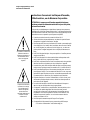
This symbol is intended to
alert you to the presence of
important operating and
maintenance (servicing)
instructions in the literature
accompanying the unit.
4.
5.
6.
7.
8.
9.
10.
This symbol is intended to
alert you to the presence of
uninsulated dangerous
voltage within the product’s
enclosure that may be of
sufficient magnitude to
constitute a risk of electric
shock to persons.
11.
12.
13.
4 E-MU Systems
Important Safety Instructions
Radio and Television Interference
A.
B.
C.
D.
E.
14.
The power supply cord has been damaged; or
Objects have fallen, or liquid has been spilled into the unit; or
The unit has been exposed to rain; or
The unit has been dropped or the enclosure damaged; or
The B-3 does not operate normally or exhibits a marked change in
performance.
All servicing should be referred to qualified service personnel.
Save These Instructions.
Radio and
Television
Interference
The equipment described in this manual generates and uses radiofrequency energy. If it is not installed and used properly —that is, in strict
accordance with our instructions— it may cause interference with radio
and television reception.
This equipment has been tested and complies with the limits for a Class B
computing device in accordance with the specifications in Subpart J of Part
15 of the FCC rules. These rules are designed to provide reasonable
protection against such interference in a residential installation. However,
there is no guarantee that the interference will not occur in a particular
installation, especially if a “rabbit ear” TV antenna is used.
If B-3 does cause interference to radio or television reception, you can try to
correct the interference by using one or more of the following measures:
•
•
•
•
•
Turn the television or radio antenna until the interference stops.
Move B-3 to one side or the other of the television or radio.
Move B-3 farther away from the television or radio.
Plug B-3 into an outlet on a different circuit than the television or radio.
Consider installing a rooftop antenna with a coaxial lead-in between the
antenna and television set.
B-3 Operation Manual 5
Foreign Language Warnings - German
Wichtige Sicherheitsvorschriften
Foreign Language Warnings
- German
Wichtige
Sicherheitsvorschriften
Erdungsinstruktionen
Gefahr
Vorsicht
6 E-MU Systems
In Ländern ausserhalb den U.S.A. können andere Kabel oder Stecker
notwendig werden. Zur Verminderung des Risikos von Feuer oder eines
elektrischen Schlages übergebe man den Service an qualifizierte Fachleute.
Das Gerät niemals Regen oder Nässe aussetzen.
Das Gerät muss geerdet sein. Bei einem Defekt oder Ausfall bietet Erdung
dem elektrischen Strom den Weg des geringsten Widerstandes und
reduziert das Risiko eines Schlages. Dieses Gerät ist mit einem geerdeten
Kabel und Stecker ausgerüstet. Der Stecker muss in eine passende,
einwandfrei montierte und geerdete Steckdose in Übereinstimmung mit
den örtlichen Vorschriften eingeführt werden.
Unvorschriftsgemässer Anschluss des Gerätes kann zum Risiko eines
elektrischen Schlages führen. Im Zweifelsfalle über die ordnungsgemässe
Erdung soll ein qualifizierter Elektriker oder eine Serviecestelle beigezogen
werden. Ändern Sie den mitgelieferten Stecker nicht. Sollte er nicht in die
Steckdose passen, soll die einwandfreie Installation durch einen qualifizierten Techniker erfolgen.
Wird der B-3 (Modell Nummer 9112) in einem Rackgestell montiert, muss
ein offener 19-Zollrahmen verwendet werden.
Foreign Language Warnings - German
Unterhaltsinstruktionen für anwender
Unterhaltsinstruktionen
für anwender
Vorsicht
1.
2.
3.
B-3 soll sauber und staubfrei gehalten werden. Das Gerät mit einem
sauberen und säurefreien Tuch periodisch abreiben. Keine Lösungsoder Reinigungsmittel anwenden.
Schmieren und Justieren sind nicht notwendig.
Bei weiteren Servicefragen wende man sich an eine qualifizierte Servicestelle.
Diese Gebrauchsanweisungen sind nur für qualifizierte Techniker
beabsichtigt. Um die Gefahr eines elektrischen Schlages zu vermeiden,
sollen Sie keine Arbeit unternehmen, die nicht in diesen Instruktionen
vorgeschrieben ist. Wenden Sie Sich bei weiteren Servicefragen an eine
qualifizierte Servicestelle.
INSTRUKTIONEN BETR. FEUERRISIKO,
ELEKTROSCHOCK ODER VERLETZUNG VON
PERSONEN
Dieses Symbol weist den
Anwender auf wichtige
Gebrauchs- und ServiceVorschriften in den beiliegenden Drucksachen.
WARNUNG; Beim Einsatz elektrischer Geräte sollten
folgende Vorsichtsmassregeln stets beachtet werden:
1.
2.
3.
4.
5.
6.
7.
Dieses Symbol verweist auf
nicht-isolierte Stromspannungen im Geräte-Innern,
welche zu einem elektrischen
Schlag führen könnten.
8.
9.
Lesen Sie vor dem Einschalten des B-3 alle Instruktionen.
Zur Vermeidung von Verletzungsrisiken müssen Kinder bei eingeschaltetem B-3 sorgfältig überwacht werden.
B-3 nicht in der Nähe von Wasser in Betrieb nehmen -- z.B. in der Nähe
von Badewannen, Waschschüsseln, auf nassen Gestellen oder am
Swimmingpool.
B-3 stets so aufstellen, dass seine Belüftung nicht beeinträchtigt wird.
B-3 nicht in der Nähe von Hitze aufstellen, wie Heizkörper, offenem
Feuer, Öfen oder von Backöfen.
B-3 ausschliesslich mit einem Netzgerät gemäss Bedienungsanleitung
und Gerätemarkierung verwenden.
Dieses Gerät kann bei Verwendung von Kopfhörern und Verstärkern
hohe Lautpegel erzeugen, welche zu bleibenden Gehörschäden führen.
Arbeiten Sie nicht während längerer Zeit mit voller Lautstärke oder
hohem Lautpegel. Stellen Sie Gehörverlust oder Ohrenläuten fest,
wenden Sie sich an einen Ohrenartz.
B-3 kann mit einem polarisierten Kabelstecker (mit ungleichen Stiften)
ausgerüstet sein. Das geschieht für Ihre Sicherheit. Können Sie den
Stecker nicht in die Steckdose einführen, ändern Sie nicht den Stecker
ab, sondern wenden Sie sich an einen Elektriker.
Das Netzkabel des B-3 bei längerem Nichtgebrauch aus der Steckdose
ziehen.
B-3 Operation Manual 7
Foreign Language Warnings - German
10.
11.
12.
Vermeiden Sie sorgfältig das Eindringen von Gegenständen oder
Flüssigkeiten durch die Gehäuseöffnungen.
Das Gerät soll durch qualifizierte Serviceleute gewartet werden, falls:
A. das Netzkabel beschädigt wurde, oder
B. Gegenstände oder Flüssigkeit in das Gerät gelangten,
C. das Gerät Regen ausgesetzt war, oder
D. das Gerät nicht normal oder einwandfrei arbeitet, oder
E. das Gerät stürzte oder sein Gehäuse beschädigt wurde.
Servicearbeiten sollten nur qualifizierten Fachleuten anvertraut werden.
DIESE INSTRUKTIONEN AUFBEWAHREN
8 E-MU Systems
Foreign Language Warnings - French
Instructions de Sécurité Importantes
Foreign Language Warnings
- French
Instructions
de Sécurité
Importantes
Instructions
de Mise à la
Terre
Danger
Attention
Instructions
de
Maintenance
Une utilisation dans des pays autres que les U.S.A. peut nécessiter l’usage
d’un cordon d’alimentation différent. Afin de réduire les risques d’incendie
ou d’électrocution, référez-vous à un personnel de service qualifié, et
n’exposez pas cet appareil à la pluie ou à l’humidité.
Cet appareil doit être relié à la terre. Dans le cas d’une malfonction
éventuelle, la terre fournit un passage de moindre résistance pour le
courant électrique, réduisant ainsi les risques d’électrocution. Le B-3 est
équipé d’un cordon muni d’un conducteur et d’une fiche devant être
branchée dans une prise appropriée et reliée à la terre en conformité avec
les normes locales.
Une connexion incorrecte peut résulter en des risques d’électrocution.
Vérifiez avec un technicien qualifié si vous avez des doutes quant à la
connexion. Ne modifiez pas vous-même le cordon d’alimentation livré avec
cet appareil; s’il ne rentre pas dans la prise, faites-en installer un autre par
un technicien qualifié.
Si le B-3 (Model 9112) est installé dans un rack, utilisez un rack standard
ouvert de 48.25cm.
2.
le B-3 doit être maintenu propre et sans poussière. Nettoyez-le
périodiquement à l’aide d’un chiffon propre et non-pelucheux.
N’utilisez pas de solvants, ou d’autres produits de nettoyage.
Aucune lubrification et aucun réglage ne sont nécessaires de votre part.
3.
Pour tout autre service, référez-vous à un personnel qualifié.
1.
B-3 Operation Manual 9
Foreign Language Warnings - French
Instructions de Maintenance
Instructions Concernant les Risques d’Incendie,
d’Electrocution, ou de Blessures Corporelles.
ATTENTION: Lorsque vous utilisez des appareils électriques,
certaines précautions élémentaires doivent toujours être prises,
incluant les suivantes:
Ces instructions de dépanage sont destinées uniquement aux personnes
qualifiées. Afin d’éviter les risques d’électrocution, n’effectuez que les opérations décrites dans ce manuel, à moins que vous ne soyez qualifiê pour cela.
Faites effectuer toute r’eparation par une personne qualifié.
1.
2.
3.
Ce symbole vous alerte de la
présence d’instructions
importantes d’opération et
de maintenance dans la
notice accompagnant
l’appareil.
4.
5.
6.
7.
8.
9.
10.
Ce symbole vous alerte de
la présence d’un voltage
non-isolé dangereux à
l’intérieur de l’appareil,
pouvant être d’une
magnitude suffisante pour
constituer un risque
d’électrocution.
11.
12.
13.
10 E-MU Systems
Lisez bien toutes les instructions avant d’utiliser le B-3.
Afin de réduire les risques de blessures, une attention particulière est
nécessaire en la présence d’enfants en bas âge.
N’utilisez pas le B-3 dans ou près d’endroits humides - par exemple près
d’une baignoire, d’un lavabo, dans les toilettes, dans une cave humide,
sur un bar fréquenté, en présence d’un bull-dog en rut, ou dans une
piscine pleine. Protégez cet appareil de tout liquide, éclaboussure ou
fuite.
Le B-3 doit être placé de façon à ce que sa position n’interfére pas avec
sa propre ventilation.
Le B-3 doit être placé loin de sources de chaleur telles que des radiateurs, cheminées, fours, ou groupies en chaleur.
Le B-3 doit uniquement être connecté à une alimentation du type décrit
dans les instructions d’opération et tel qu’indiqué sur l’appareil.
Une attention particulière doit être observée quant aux objets pouvant
tomber et aux liquides pouvant être versés sur et à l’intérieur de le B-3.
Le B-3 peut être équipé d’une fiche secteur polarisée (avec une broche
plus large que l’autre). C’est une mesure de sécurité. Si vous ne pouvez
pas brancher cette fiche dans une prise, ne neutralisez pas cette sécurité.
Contactez plutôt un électricien pour remplacer la prise obsolète.
Evitez de marcher sur le cordon d’alimentation ou de le coincer, particuliêrement prês des prises de courant, des boitiers ‘electriques dt du
point de sortie de l’appareil.
Le cordon d’alimentation de le B-3 doit être débranché lorsque ce
dernier n’est pas utilisé pendant une longue période.
Cet appareil, combiné avec un amplificateur, des haut-parleurs, et/ou
un casque, est capable de générer des niveaux sonores pouvant
occasionner une perte de l’ouïe permanente. Ne travaillez pas trop
longtemps à un volume trop élevé ou même inconfortable. Si vous
observez une perte de l’audition ou un bourdonnement dans les
oreilles, consultez un O.R.L.
N’utilisez que les accessoires sp’ecifi’es par E-mu Systems.
Cet appareil doit être examiné par un personnel qualifié lorsque:
A. Le cordon d’alimentation a été endommagé, ou
Foreign Language Warnings - French
Interférences Radio et Télévision
14.
B. Des objets sont tombés, ou du liquide a été versé sur/à l’intérieur
de l’appareil, ou
C. Le B-3 a été exposé à la pluie, ou
D. Le B-3 est tombé, ou
E. Le B-3 ne fonctionne pas normalement, ou affiche un
changement radical de performance.
Tout service doit être effectué par un personnel qualifié.
SAUVEGARDEZ CES INSTRUCTIONS
Interférences
Radio et
Télévision
L’appareil décrit dans cette notice génére et utilise une énergie de
fréquence-radio. S’il n’est pas installé et utilisé correctement - c’est à dire en
suivant strictement nos instructions - il peut occasionner des interférences
avec la réception d’une radio ou d’une télévision.
Cet appareil a été testé et est conforme aux normes de Classe A en accord
avec les spécifications du paragraphe J de la section 15 des lois FCC. Ces lois
sont désignées pour fournir une protection raisonnable contre de telles
interférences dans une installation résidentielle. Toutefois, il n’est pas
garanti qu’aucune interférence n’apparaisse dans des installations particulières, et plus spécialement lorsqu’une antenne de télévision en «oreilles de
lapin» est utilisée.
Si le B-3 occasionne des interférences , vous pouvez essayer de les corriger
en utilisant une ou plusieurs des mesures suivantes:
• Tournez l’antenne de la télé ou de la radio jusqu’à ce que les interférences disparaissent.
• Déplacez le B-3 d’un côté ou de l’autre de la télé ou de la radio.
• Eloignez le B-3 de la télé ou de la radio.
• Branchez le B-3 sur une prise différente que la télé ou la radio.
• Installez une antenne sur le toit munie d’une connexion coaxiale entre
elle et le poste de télévision.
B-3 Operation Manual 11
DECLARATION OF CONFORMITY
Interférences Radio et Télévision
DECLARATION OF CONFORMITY
Manufacturer:
E-MU/Ensoniq
1600 Green Hills Road
Scotts Valley, CA 95067-0015 USA
We hereby declare that the equipment listed herin conforms to the
harmonized standards of the following European Commission Directives:
89/336/EEC and 72/23/EEC.
Trade Name:
Audio Sampler/Emulator System
Model Number:
Proteus 1000 CR
Under 89/336/EEC as amended by 92/31/EEC, and 72/23/EEC
In accordance with EN 55103-1:1996, Emission Environments E1, E2, E3
In accordance with EN 55103-2:1996, Immunity Environments E1, E2, E3
Test information is contained in a report by Atlas Compliance and
Engineering dated November 15, 1999.
Report No.: 9949EMU2KCR103
Under 73/23/EEC as amende by 93/68/EEC
In accordance with EN 60950 with amendments A1, A2, A3, A4, A11
This Declaration is made November 15, 1999
12 E-MU Systems
Setup
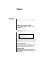
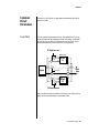
This section thoroughly describes how to set up your new B-3 for use. Setup
includes unpacking instructions and how to connect the cables.
Unpacking
Carefully remove B-3 from the packaging material. Take care to save the
packing materials in case you need to transport the unit. Check to make
sure all components are included and in good condition. If there are
missing or damaged components, contact E-MU Systems immediately for
replacement or repair.
The B-3 box should include the following components:
•
•
•
•
B-3 rack unit
Power cable
Rack mounting ears
This Operation Manual
B-3 Operation Manual 13
Setup
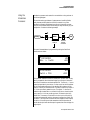
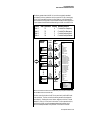
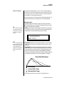
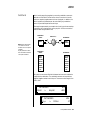
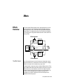
Connection Instructions
Connection
Instructions
Set Footswitch - Controller #64
Set Control Pedal - Controller #7
REAL
TIME
The Headphone
Output is located
on the Front Panel
CONTROLLERS
ASSIGNABLE
KEYS
PRESET
LEVEL
EXIT
ENTER
SAMPLE
PAGE
SEQUENCER
PRESET SELECT
1
2
3
4
5
6
RETURN
7
8
9
0
.
EMULATOR
Basic Setup
MIDI Out
Control
Pedal
Footswitch
~
If B-3 does not seem to
be responding correctly, make
sure that both B-3 and your
MIDI controller are set to the
same MIDI channel.
A
B
THRU
SCOTTS VALLEY CA. U.S.A.
Main Outs to Mixer In
IN
To
Main Outs
Male RCA plug
to
Male Phono Plug
Mixer
Aux. or
Tape In
Amp
Speakers
Home Stereo
System
The Right Main output
jack serves as a mono output
when the Left Main plug is not
plugged in.
The Left Main output jack is a
stereo jack carrying both
channels.
Home Studio
System
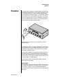
MIDI In
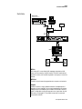
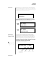
B-3 is controlled by MIDI messages received at the MIDI In jack. Normally
you will connect MIDI Out of a controller such as a MIDI keyboard to the
MIDI In jack of B-3. Be sure to connect a Footswitch and Control Pedal to
your MIDI keyboard to take advantage of the factory presets. Set your MIDI
Keyboard so that the Footswitch send MIDI Controller #64 (rotating
speaker) and the Control Pedal sends MIDI Controller #7 (Volume).
Outputs
In order to reproduce B-3’s wide dynamic range and frequency response,
use a high quality amplification and speaker system such as a keyboard
amplifier or home stereo system. A stereo setup is highly desirable because
of the added realism of stereophonic sound. Headphones can be used if an
amplifier and speaker system is not available. Plug stereo headphones into
the headphone jack located on the left side of the front panel.
14 E-MU Systems
Setup
Connection Instructions
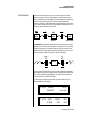
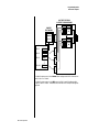
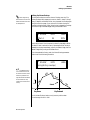
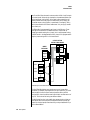
Studio Setup
MIDI Controller
(MIDI Keyboard, Sequencer, etc.)
REAL
TIME
CONTROLLERS
ASSIGNABLE
KEYS
PRESET
LEVEL
EXIT
ENTER
SAMPLE
PAGE
SEQUENCER
PRESET SELECT
1
2
3
4
5
6
RETURN
7
8
9
0
.
Computer
EMULATOR
MIDI In
Additional
MIDI
Devices
MIDI Out
MIDI In
In
MIDI
Interface
Out
Out
In
“A” MIDI
channels
1-16
~
A
B
IN
THRU
SCOTTS VALLEY CA. U.S.A.
Mixer
Amp
MIDI In
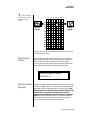
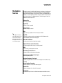
In this setup, B-3 is controlled by MIDI messages, received at the MIDI
input, which are routed by the MIDI interface. The MIDI interface allows
any MIDI controller, such as a MIDI keyboard or a computer, to control the
module.
MIDI Out
The MIDI Out jack transmits program data to a computer or other device.
Outputs
A stereo connection is highly desirable because of the added realism of
stereophonic sound, especially for the rotating speaker effects. Plug stereo
headphones into the headphone jack located on the left side of the front
panel. The Right Main output jack serves as a mono output when the Left
Main plug is not plugged in. The Left Main output jack is a stereo jack
carrying both channels.
B-3 Operation Manual 15
Setup
Connection Instructions
Power Up!
The power switch is located on the right side of the front panel. You can
turn on the B-3 and its MIDI controller in any order. When power is applied
the liquid crystal display will light, indicating that B-3 is operating. You
may have noticed that there is no 110/220 Volt power selector switch on
B-3.
B-3 automatically switches itself to the proper
line voltage.
16 E-MU Systems
Setup
Instant Gratification
Instant
Gratification
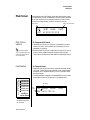
Playing Demo
Sequences
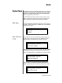
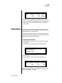
This section presents step-by-step instructions for the most fundamental
operations to get you up and making sounds quickly.
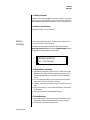
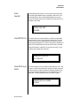
B-3 has several factory demonstration sequences that let you hear what this
incredible machine can do. The actual number of demo sequences depends
on which ROM sounds sets are installed. You can play these demo
sequences by accessing the Demo Sequence page.
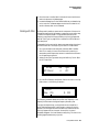
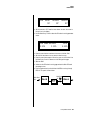
DEMO SEQUENCES
B3 Madness
þ
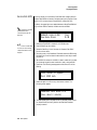
1.
2.
3.
B3
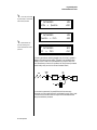
To Play a Demo Sequence
Press and hold the Master and Edit buttons at the same time to enter
the Demo Sequence page. The screen shown above appears.
Select a sequence using the data entry control. The Enter LED will be
flashing.
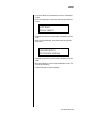
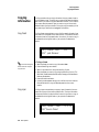
Press the Enter button to begin playing the selected sequence. The
screen shown below appears.
PLAYING: B3 Madness
Press ENTER to stop
4.
5.
6.
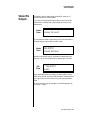
Auditioning Presets
Press the Enter button again to stop playing the sequence.
When a demo sequence plays to the end, the next demo will automatically begin playing. The screen will display the new demo name.
With the sequence stopped, press either the Master, Edit or Multi
button to Exit the demo sequence mode.
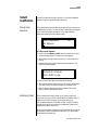
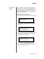
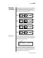
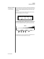
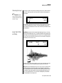
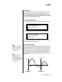
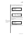
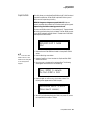
The front panel audition button allows you to hear any preset in B-3
without even hooking up a MIDI keyboard! When the Audition button is
pressed, the LED next to the button will illuminate and a short
“Riff” (programmed as part of the preset) will play. The Riff is latched on
and plays continuously until the button is pressed again. Presets can be
changed while Audition is latched on.
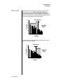
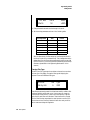
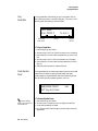
The top line of the display changes to show the MIDI Bank Select controller
values needed to select the preset being auditioned. This is an extremely
handy feature when sequencing.
B-3 Operation Manual 17
Setup
Instant Gratification
BankSel 0:000 32:2
0190
org: 808800008
þ
1.
2.
3.
4.
Selecting and Quick
Editing Presets
B-3
To Audition a Preset
Select a preset by turning the data entry control while the cursor is
anywhere on the lower line. The preset number field (shown above) is
the normal position of the cursor and pressing the Enter button will
return the cursor to this position.
Press the Audition button on the front panel. The Audition LED will
illuminate and a short riff will play the selected preset.
Continue to select and audition presets.
Press the Audition button again to turn Audition mode off. The LED
will extinguish.
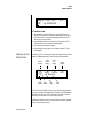
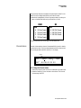
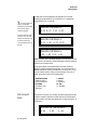
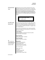
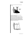
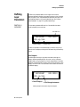
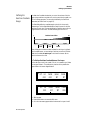
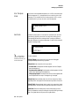
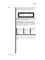
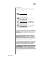
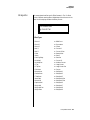
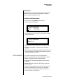
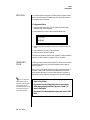
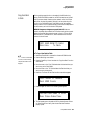
The first thing you’ll do with the B-3 is select and play the factory provided
presets. B-3 comes standard with 7 banks containing 128 presets each.
Channel
Number
C01
0702
Preset
Number
Initial
Volume
Setting
Initial
Pan
Setting
Preset
Location
Vol127
Pan01R
org: Beasty B
Bank
Number
Preset
Category
User
Preset
Name
The first four banks are USER locations that can be overwritten and used to
store your own presets. The presets that come stored in the USER presets are
duplicated in banks 0-2 of the “B-3” ROM bank, so feel free to overwrite
them with your own presets. You won’t be losing anything.
The ROM Card identifier is shown in the top right of the display. The preset
is identified in the bottom line of the main screen (the screen that appears
when you first power up the unit).
18 E-MU Systems
Setup
Instant Gratification
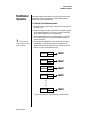
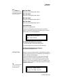
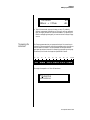
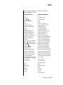
Each bank of 128 presets is identified by a superscripted Bank Number to the
right of the preset number. The bank numbers reset to 0 at the start of each
ROM card you have installed. So with the B-3 ROM installed, the USER
banks will go from 0-3, then start over from 0-2 for the B-3 ROM banks.
To the right of the preset number and bank is the preset Category name
followed by the Preset Name.
þ
1.
O
You can select presets
from the Preset Number, Bank
Number, Preset Category or
Preset Name fields.
2.
3.
4.
To Change the Preset
Place the cursor under the first character in the Preset Number field.
This is the “Home” position which is selected instantly when you press
the Home/Enter button. Pressing either of the two cursor buttons
repeatedly also gets you there.
Turn the Data Entry Control knob on the front panel to select a new
preset number. If you turn the knob slowly, the presets advance one
number for each “click” of the knob. If you spin the knob quickly, the
numbers advance much faster (more than one number per click).
Play the keyboard (or press the Audition button) and listen to the
sounds made by your B-3!
TURN THE FOUR KNOBS on the front panel and note how they
change the sound of each preset! The button to the left of the knobs
changes the knob’s function. Don’t worry about ruining the sound, the
values are automatically reset as soon as you select a new preset.
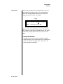
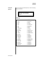
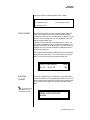
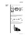
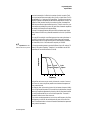
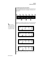
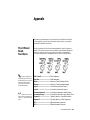
Bank Organization
}
The User Banks
are duplicated
in the B-3
ROM bank.
USER
USER
USER
USER
Bank 0
Bank 1
Bank 2
Bank 3
128 Presets
128 Presets
128 Presets
128 Presets
B3
B3
B3
Bank 0
Bank 1
Bank 2
128 Presets
128 Presets
128 Presets
The four User Banks can hold 512 custom presets. Feel free to overwrite
these since the factory user presets are duplicated in nonvolatile ROM.
B-3 Operation Manual 19
Setup
Instant Gratification
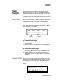
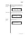
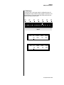
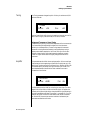
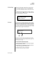
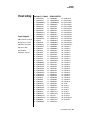
Bank Select
Commands
When you press the Audition button, the Bank Select MSB and LSB are
displayed on the top line of the display.
Bank Select Commands allow you to access more than 128 preset via MIDI.
Continuous Controllers 0 and 32 are used to select banks of 128 presets
each. Continuous Controller (CC) 0 is the MSB (most significant byte) and
CC 32 is the LSB (least significant byte). Normally you send both the MSB
and LSB controllers to implement a bank change.
B-3 remembers the MSB and the LSB that were last sent (or last changed
from the front panel). For example, if you have already set the Bank MSB to
06, you need only send the LSB to change banks within the B-3 sound set.
See the MIDI Bank Select chart below.
The selected bank remains selected until you change it (either via MIDI or
by changing the bank from the front panel). Standard MIDI Program
Change commands select from 128 presets within the selected bank.
MIDI BANK SELECT
MSB LSB
cc00 cc32
20 E-MU Systems
USER
USER
USER
USER
00
00
00
00
00
01
02
03
Bank 0
Bank 1
Bank 2
Bank 3
B3
B3
B3
06
06
06
00
01
02
Bank 0
Bank 1
Bank 2
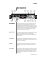
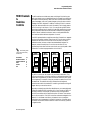
Basic Operations
Front Panel
Basic Operations
Control
Button
A-D
E-H
I-L
Volume
Control
FILTER
FIL
TER CUTOFF
LAYER
LA
YER 1
DYNAMIC 1
FILTER
FIL
TER RES
LAYER
LA
YER 2
DYNAMIC 2
ATT
TTACK
ACK
PERC AMOUNT
FX A
RELEASE
PERC DECAY
DECAY
FX B
MASTER
CO 1
Vo l 1 27 Pan0 1 R
022 3 o r g : P e r c o l a t o r
VOLUME
A/E/I
B/F/J
Edit
Menu
Master
Menu
C/G/K
B3
Cursor
Controls
Power
Switch
EDIT
DEMOS
POWER
D/H/L
AUDITION
MULTI
MUL
TI
SAVE/COPY
SA
VE/COPY
HOME/ENTER
MIDI
Display
Headphone
Jack
Front Panel
Realtime
Control Knobs
Audition
Button
Multisetup
Button
Save/
Copy
Home/
Enter
Data
Entry
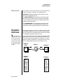
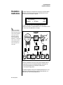
The B-3 front panel contains an LCD screen, nine buttons and four realtime controllers. Functions are grouped logically and the controls are
arranged for ease of use. Precisely because B-3 is so simple to use, you might
be tempted to skip this section. If you just can’t help yourself, at least read
the Real-time Controller information beginning page 23. There are several
“power user” features in the interface which make programming even
easier and we wouldn’t want you to miss them.
Volume Control
This control is the master volume control for all audio outputs. The Volume
Control does not affect any editing or user interface operations.
Note: For maximum dynamic range and smoothest crossfading, set this
control to full level.
Master Button
The Master menu contains parameters that affect the entire machine, not
just certain presets. An illuminated LED to the right of the button indicates
that you are in the Master menu.
Edit Button
Use the Edit menu when you want to create or modify a preset. An illuminated LED to the right of the button indicates that you are in the Edit
menu.
Control Button
The Control button is used to change the function of the Controller knobs
(see the next section). Each time you press the Control button, the Control
Mode toggles to select only one of the three Control Rows. The currently
selected Control Row is indicated by one of the three LEDs to the right of
the row’s label.
B-3 Operation Manual 21
Basic Operations
Front Panel
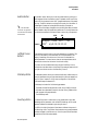
Audition Button
O
See “Bank Select
Commands” on page 80 for
more information on selecting
banks via MIDI.
The Audition button allows you to hear any preset without hooking up a
MIDI keyboard. When the Audition button is pressed, the LED next to the
button will illuminate and a short “Riff” (programmed as part of the preset)
will play. The Riff is latched on and plays continuously until the button is
pressed again. Presets can be changed while Audition is latched on.
The top line of the display changes to show the MIDI Bank Select controller
values needed to select the preset being auditioned. This handy feature lets
you know the exact Bank and Preset number to enter into your sequencer.
MSB
Preset #
Left/Right Cursor
Buttons
LSB
BankSel 0:006 32:3
B3
3
002
org: 8 0 8 0 8 8 0 6 3
These buttons move the cursor to the next parameter on the display. (The
cursor is a little flashing line underneath one of the parameters in the
display.) Press either cursor button until the cursor is underneath the
desired parameter. The cursor buttons have an auto-repeat feature which
advances the cursor when the button is held continuously.
The cursor can be moved bidirectionally using the Data Entry Control
while either cursor select button is held down (for example, press and hold
the right cursor button and turn the Data Entry Control).
Multisetup Button
The Multisetup button allows you to select a Multi-setup. A Multi-setup is a
group of parameters that you might associate with a particular sequence or
song. It is like a “snapshot” of the current configuration of the module.
There are 64 setups numbered 0-63.
A Multisetup includes all of the following parameters:
• The Preset/Volume/Pan assignments for each of the 16 MIDI channels.
• All Master menu parameters, except for the User Tuning Tables and the
MIDI program change->preset map.
• The Multisetup name.
Save/Copy Button
The Save/Copy button is used to save or copy presets and to copy data.
Selected groups of parameters, such as PatchCord settings, can be copied
between Presets and/or between Layers using this menu.
The LED to the right of the button illuminates to indicate that you are in
the Save/Copy menu. The LED also illuminates when any preset parameter
has been changed in the Edit menu (or if the front panel knobs have been
moved with Quick-Edit mode enabled).
22 E-MU Systems
Basic Operations
Front Panel Controller Modes
Home/Enter Button
The Home/Enter button is dual purpose. In general, this button acts as the
“Home” button. For example, when in an Edit menu, this button snaps the
cursor to the page name field of the current screen. When viewing the
Preset Select screen (we also call it the main screen), this button snaps the
cursor to the preset number field. In these instances, the LED is not used.
Some screens and parameter fields use this button as the “Enter” button. In
these cases, the LED blinks when the cursor is moved to one of these fields
indicating that the module is waiting for your response to initiate the
operation.
Data Entry Control
The Data Entry Control is a stepped, variable control switch used to change
parameter values. The wheel increments or decrements the current value
one unit with each click. This control incorporates acceleration, which
advances the value faster if the Data Entry Control is turned quickly.
Controller Knobs
Each of the four Real-time Controller knobs has a corresponding LED to its
upper right side. The function of the Real-time Controllers depends on
which row is currently selected and the programming of the preset.
Front Panel
Controller
Modes
The Real-time Controller Knobs serve three purposes:
1.
2.
3.
Real-time control of synthesizer parameters
“Quick Editing” the initial settings of the real-time controllers
“Deep Editing” the parameters
This section describes each of the three uses.
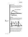
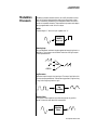
Real-time Control
The Real-time controller knobs provide direct control of the B-3’s synthesizer parameters. They are always active when on the Preset Select (main)
screen. They can optionally be used to transmit MIDI controller messages
to other MIDI devices.
The Control button (left of the knobs) changes the function of the real-time
controller knobs. Each time the button is pressed, the Control Mode toggles
to select one of the three Control Row groups. The currently selected
Control Row is indicated by the illuminated LED to the right of the button.
The control knob functions are determined by the selected Control Row.
The three Control Rows generate MIDI data that can control the preset on
the current MIDI channel (the channel showing on the Preset and main
screen. The labels (Tone, Presence, Shape, Image, etc.) printed on these rows
show how the factory ROM presets may be programmed to respond. (The
controls might not conform to the front panel labels depending on the preset.) You
can change the way a preset responds to MIDI A-L messages from the Edit
menu (PatchCords).
B-3 Operation Manual 23
Basic Operations
Front Panel Controller Modes
There is an LED next to each of the control knobs which illuminates to
indicate that the knob setting has been changed from the value
programmed in the preset (when Quick Edit mode is enabled). If the knob
position is returned to the original setting, the LED is extinguished.
If the “Knobs MIDI Out” parameter in the Master menu (see “Knobs/Riff
MIDI Out” on page 48) is set to “transmit,” the system sends a MIDI
controller message when you turn off the Control knob. The MIDI
controller message is sent on the current MIDI channel (also called the
basic channel) using the controller number assigned in the Master menu
(see “Real-time Controller Assignment” on page 45).
The knobs only generate a message when you move a knob to a new value.
The current value jumps to the new value.
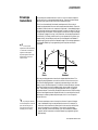
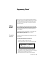
Quick Edit
This mode uses the Controller knobs to “Quick-Edit” the currently selected
preset without having to enter the Preset Edit menu. This mode is only
active when on the Preset Select screen and when “Quick-Edit” is enabled in
the Master menu (see “Knob Preset Quick-Edit” on page 47).
Initial controller values can be stored in every preset. When you move a
knob with Quick-Edit enabled, the Initial Controller Value is updated with
the knob’s new value. The knob’s LED lights indicating that the preset value
has been changed. The three Control Rows’ MIDI A-L values are stored in
the corresponding Initial Controller Amount parameter in the Edit menu
(see “Initial Controller Amount” on page 123). The Save/Copy button LED
illuminates to remind you that the preset has been edited. “Quick-Edits”
made to a preset are lost if you select another preset before saving them.
_
Quick-Edit mode must
be enabled in the Master menu.
þ
1.
2.
3.
4.
5.
24 E-MU Systems
To Quick-Edit a Preset
Use the Control Knobs to change the sound of the current preset as
desired.
Press the Save/Copy button. The display reads, “Save Preset to.”
Press the right cursor button to select the bottom row.
Optional: Select a new preset location if you don’t want to overwrite
the current preset, or if the current preset is a ROM preset.
Press the Enter button to save the preset.
Basic Operations
Front Panel Controller Modes
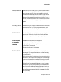
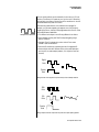
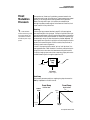
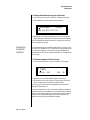
Deep Edit Mode
When in the Master, or Edit menus, you can use the Controller Knobs to
edit parameters. Using the Controller Knobs is a faster method for entering
data, but the Data Entry Control offers finer precision.
þ
1.
To Enable Deep Edit Mode:
Press the Master button and use the Data Entry Control to advance to
the “Knobs Deep Edit” screen as shown in the following illustration.
KNOBS DEEP EDIT
disabled
2.
3.
4.
Press either Cursor key to move the cursor to the bottom line in the
display.
Use the Data Entry Control to change the value to “enabled.”
Press the Master menu button to exit the Master menu.
When you enter any of the Edit menus:
1.
2.
3.
The four Controller Knobs are used for editing.
All the Controller LEDs are off.
All the Control Row LEDS are off.
When you turn a knob, the field value jumps to the current knob value.
You can still use the Data Entry Control for editing by moving the cursor to
the desired field.
L1
A/E/I
KEY: LO
C-2
FADE
000
B/F/J
HIGH
G8
C/G/K
FADE
000
D/H/L
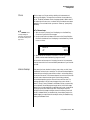
To move through menus horizontally, use the Data Entry Control (the
page’s title field is the default cursor position). To move through menus
vertically (preset layers), press the left cursor to get to the layer field, then
change layers with the Data Entry Control.
• Use the Data Entry Control to move through menus (horizontally) or
layers (vertically).
• Use the Controller Knobs to change parameter values within each page.
B-3 Operation Manual 25
Basic Operations
Main Screen
Main Screen
The Preset Select screen is B-3’s default screen (also called the main screen)
and is active when you have not selected any of the other button-activated
menus. From this screen you can change or examine the Preset, Volume,
Pan Position and Preset Location for each of the 16 MIDI channels.
MIDI Channel
MIDI Channel
Selection
The channel number
shown in the main screen is the
“basic MIDI channel” when in
Omni or Poly modes.
Preset Selection
þ
1.
2.
þ
1.
2.
Contents
128 RAM Presets
128 RAM Presets
128 RAM Presets
128 RAM Presets
128 ROM Presets
128 ROM Presets
128 ROM Presets
??
Depending on
ROM sets installed
ROM 1
USER
Bank
0
1
2
3
0
1
2
The USER preset banks can
be modified or replaced with
your own sounds.
26 E-MU Systems
ROM or RAM Preset Location
C01
Vol127
Pan01R
USER
0431
dir: 8 8 6 3 2 2 5 8 8
To Change the MIDI Channel
Press either cursor button until the cursor is underneath the channel
number. (The cursor is the little flashing line underneath one of the
parameters in the display.)
Rotate the Data Entry Control to select a MIDI channel (01-16). As the
channel number changes, the display changes to show the preset,
volume, pan and preset location associated with the displayed channel.
To Change the Preset
Press either cursor key until the cursor is underneath the preset number.
(The cursor is a little flashing line underneath one of the parameters in
the display.) As you rotate the Data Entry Control, the preset number
and name changes.
The displayed preset is assigned to the displayed MIDI channel. Presets
are arranged into banks of 128, as shown in the diagram at left.
Bank Number
Preset
Number
C01
Vol127
Pan01R
0432 var: 1 s t 4 D i s t
USER
Basic Operations
Main Screen
Using the screen above as an example, the superscripted number 2 in the
second line of the display identifies the current bank number.
• Select banks independently of the of the preset number by locating the
cursor on the Bank field and turning the Data Entry Control.
USER
B3
Bank
0
1
2
3
Bank
128 User Presets
128 User Presets
128 User Presets
128 User Presets
0 128 ROM Presets
1 128 ROM Presets
2 128 ROM Presets
The Bank numbers start at zero for each ROM sound set installed in B-3.
Channel Volume
Channel Volume sets the volume of the selected MIDI channel in relation
to the other channels. This is the same parameter as MIDI volume control
#7, and changes made over MIDI are shown in the display.
Volume
C01
0431
þ
1.
2.
Vol127
Pan01R
USER
dir: 8 8 6 3 2 2 5 8 8
To Change the Channel Volume
Press either cursor key until the cursor is underneath the volume value.
Rotate the Data Entry Control to select a volume level. The Channel
Volume range is 000-127.
B-3 Operation Manual 27
Basic Operations
Main Screen
Channel Pan
Channel Pan sets the stereo position of the selected MIDI channel. This
control operates like the balance control on your home stereo system.
Channel Pan is the same parameter as MIDI pan controller #10, and
changes made over MIDI are shown in the display.
Pan Position
C01
0431
Vol127
Pan01R
USER
dir: 8 8 6 3 2 2 5 8 8
Note: Pan settings in the preset ADD algebraically with the Channel Pan
setting. Therefore, if the pan setting in the preset were set to “63R,” moving
the Channel Pan setting full left would return the sound to the center
position.
þ
1.
2.
28 E-MU Systems
To Change the Channel Pan
Press either cursor key until the cursor is underneath the pan field.
Rotate the Data Entry Control to select a pan value. 64L indicates a hard
left pan, 63R indicates a hard right pan. With a setting of “00,” the
sound is centered in the stereo field.
Basic Operations
Sound Navigator
Sound
Navigator
Preset Category
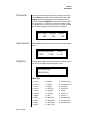
Sound Navigator allows you to search through preset and instrument
categories to find the type of sound you’re looking for. Each preset and
instrument has a name and a three letter preset category. You can create
your own categories in order to group favorite presets. The preset category
is assigned in the Edit menu (Preset Name). Instrument categories are fixed.
When you want to find presets in a particular category, you simply change
the category field in the main screen, then move the cursor to the preset
name field to scroll through all the presets in the selected category.
When the cursor is on the Preset Category field, turning the Data Entry
Control selects different preset categories. The Name Field will change to
show the first preset in each category.
C01
Vol127
Pan00
0431
dir: 8 8 6 3 2 2 5 8 8
Preset Category
þ
1.
2.
þ
1.
2.
Instrument Category
USER
Preset Name
To Change the Preset Category
Press either cursor key repeatedly until the cursor is underneath the
preset category field.
Rotate the Data Entry Control to select one of the preset categories.
Preset Categories are displayed in alphabetical order.
To Select a Preset within a Category
After selecting a category, move the cursor to the Preset Name field.
Rotate the Data Entry Control to scroll through the presets in the
selected category. Note that the preset numbers will no longer change
sequentially.
When the cursor is on the Instrument Category field (Edit menu), turning
the Data Entry Control selects different instrument categories. The Name
Field changes to show the first instrument in each category. Move the
cursor back to the instrument number to select instruments in the selected
category.
L1
INSTRUMENT
0043
ROM:B3
dir: 8 8 6 3 2 2 5 8 8
B-3 Operation Manual 29
Basic Operations
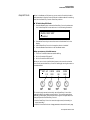
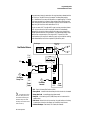
Multitimbral Operation
Multitimbral
Operation
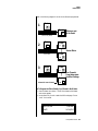
Multitimbral operation means that B-3 can play more than one sound at
the same time. Follow these instructions to access multiple presets on
different MIDI channels simultaneously.
þ
1.
2.
3.
O
Save the Multisetup
using the instruction provided in
Chapter 3:Multisetup.
4.
To Set Up B-3 for Multitimbral Operation
Set the MIDI mode to “multi mode,” using the MIDI mode function in
the Master menu.
Decide which MIDI channels you want the B-3 to receive (16 channels
can be used simultaneously). You can turn any unused channels OFF
using the MIDI Enable function in the Master menu.
Select the desired preset for each of the MIDI channels you want the
B-3 to receive using the MIDI Channel/Preset selection screen (see
previous instructions).
B-3 now responds multitimbrally on each of the MIDI channels you
have specified. The volume and pan position parameters can be
adjusted over MIDI (for each MIDI channel) or using the Cursor and
Data Entry Control in the Preset Select screen.
Channel 01
Volume
Pan
PRESET
Channel 02
Volume
Pan
PRESET
Channel 03
Volume
Pan
PRESET
Channel 04
Volume
Pan
PRESET
Channel 16
Volume
Pan
PRESET
Each of the 16 MIDI channels can be assigned to play a specific B-3 preset.
30 E-MU Systems
Multisetup
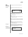
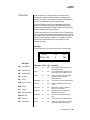
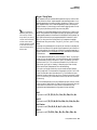
Multisetups
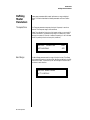
The Multisetup button allows you to save and restore Multisetups. A Multisetup is a group of parameters that you might associate with a particular
sequence or song. It is like a “snapshot” of the current MIDI channel
configuration of the module. There are 64 setups numbered 0-63. All Multisetups are user programmable.
A Multisetup includes ALL the following parameters:
• Preset/Volume/Pan assignments for each of the 32 MIDI channels.
• Multisetup Name
• ALL MASTER MENU PARAMETERS
except…
• MIDI Program Change->Preset map
• User Key Tuning Tables
RESTORE MULTISETUP
003
BT&MG
Multisetups can also be restored (selected) via MIDI Bank and Program
change commands. Select: cc00 = 80, cc32 = 00, (dec) then send a Program
Change command corresponding to the Multisetup you wish to select.
þ
To Enable the Multisetup Menu
Press the Multi button, lighting the LED. The Multisetup screen displays the
menu page most recently selected since powering up B-3. The cursor
appears below the first character of the screen heading on line one.
þ
To Select a New Screen
Press the Home/Enter button or press the Cursor button repeatedly until
the cursor is below the screen title heading. Rotate the Data Entry Control
to select another screen.
B-3 Operation Manual 31
Multisetup
Multisetups
þ
To Modify a Parameter
Press either Cursor button repeatedly (or hold down the left or right cursor
button while turning the Data Entry Control) until the cursor is below the
desired parameter value. Rotate the Data Entry Control to change the value.
þ
To Return to the Main Screen
Press the Multi button, turning off the LED.
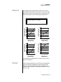
Restoring
Multisetups
B-3 contains 64 Multisetup locations. These are all User locations which
you can use to store your own Multisetups.
Multisetups can also be restored using a MIDI Bank Select command.
Select: cc00 = 80, cc32 = 00, (dec) then send a Program Change command
corresponding to the Multisetup you wish to select.
RESTORE MULTISETUP
003
þ
1.
2.
3.
4.
5.
þ
1.
2.
32 E-MU Systems
Jazz Encounter
To Restore (Select) a Multisetup:
Press the Multi menu button lighting the LED. The Multi menu screen
displays the menu page most recently selected since powering up B-3.
The cursor appears below the first character of the screen heading on
line one.
Go to the “Restore Multisetup” screen (shown above) using the Data
Entry Control. This is the first screen in the menu.
Press either cursor button to move the cursor to the bottom line of the
screen.
Now, use the Data Entry Control to select a Multisetup. The Enter LED
will be flashing.
Press the Enter button to load the selected Multisetup.
To Save a Multisetup:
Set the Preset, Volume, Pan settings the way you want them for all 16
channels. Set the Master menu parameters the way you want them.
Press the Multi menu button lighting the LED.
Multisetup
Multisetups
3.
4.
If you wish to Name your new Multisetup continue on, otherwise skip
to step 8.
Scroll to the “Setup Name” screen (shown below) using the Data Entry
Control.
SETUP NAME
020 User Setup 23
5.
6.
Press either cursor button to move the cursor to the bottom line of the
screen.
Scroll to the “Save Multisetup” screen (shown below) using the Data
Entry Control.
SAVE MULTISETUP to
020 Destination Multisetup
7.
8.
9.
Press either cursor button to move the cursor to the bottom line of the
screen.
Now, use the Data Entry Control to select the destination location. The
Enter LED will be flashing.
Press the Enter button to save the Multisetup.
B-3 Operation Manual 33
Multisetup
Multitimbral Sequencing
Multitimbral
Sequencing
“Multitimbral” means that B-3 can play multiple sounds at the same time.
For a multitimbral sequence to play back correctly, the proper preset must
be selected for each MIDI channel. This could be done by inserting preset
changes into each track of your sequence before the sequence starts. B-3
also provides another way to store this “pre-sequence setup” using the
Multisetup menu.
Using Multisetups, you’ll set up the preset, volume and pan settings for
each MIDI channel as you build your sequence, then save the Multisetup
when it’s the way you want it. Sending one preset change command before
the sequence starts selects the Multisetup and MIDI settings for all 16
channels.
þ
1.
2.
3.
Set the MIDI mode to “multi mode,” using the MIDI mode function in
the Master menu.
Decide which MIDI channels you want B-3 to receive (up to 16
channels can be used simultaneously). You can turn any unused
channels OFF using the MIDI Enable function in the Master menu.
Select the desired preset for each of the MIDI channels you want the
B-3 to receive using the MIDI Channel/Preset selection screen. You can
also set the initial Volume and Pan settings for each channel.
1. Select Channel
C01
Vol127
2. Select Preset
0431
dir: 8 8 6 3 2 2 5 8 8
Pan00R
USER
4.
B-3 now responds multitimbrally on each of the MIDI channels you
have specified. The volume and pan position parameters can be
adjusted dynamically over MIDI (during the sequence).
5.
Save the Multisetup.
þ
1.
2.
34 E-MU Systems
To Set up B-3 for Multitimbral Operation
To Link a Multisetup with your Sequence
Insert a MIDI bank and program change in the lead-in measure of your
sequence to select the proper Multisetup before the sequence starts.
The Multisetup will now be selected before the sequence starts.
Master Menu
The Master menu contains functions that affect the overall operation of
B-3. For example, changing the Master Tune parameter changes the tuning
of all the presets, not just the one currently displayed.
þ
To enable the Master menu
Press the Master button, lighting the LED. The Master Menu screen displays
the menu page most recently selected since powering up B-3. The cursor
appears below the first character of the screen heading on line one.
_
Warning: Master Menu
changes are automatically
saved when you exit the
module. If the power is turned
off before you exit the module
any changes you have made will
be lost.
þ
To select a new screen
Press the Home/Enter button or press the Cursor button repeatedly until
the cursor is below the screen title heading. Rotate the Data Entry Control
to select another screen.
þ
To modify a parameter
Press either Cursor button repeatedly (or hold down the right cursor button
while turning the Data Entry Control) until the cursor is below the desired
parameter value. Rotate the Data Entry Control to change the value.
þ
To return to the main screen
Press the Master button, turning off the LED.
B-3 Operation Manual 35
Master Menu
Defining Master Parameters
Defining
Master
Parameters
Transpose/Tune
Master setup parameters affect overall performance, range, and global
effects. This section describes the Master parameters and how to define
them.
The Transpose parameter transposes the key of all presets, in semitone
intervals. The transpose range is ± 24 semitones.
Master Tune adjusts the fine tuning of all presets so that you can tune B-3
to other instruments. The master tuning range is ± 1 semitone in 1/64th
semitone increments (1.56 cents). A master tune setting of “+00” indicates
that B-3 is perfectly tuned to concert pitch (A=440 Hz).
MASTER TRANSPOSE
+00 semitones
Bend Range
The Bend Range parameter sets the range of the pitch wheel. This affects
only presets that have their individual Pitch Bend range (defined in the Edit
menu) set to Master. The maximum pitch bend range is ±12 semitones or
one octave in each direction.
MASTER BEND RANGE
+/- 7 semitones
36 E-MU Systems
TUNE
+00
Master Menu
Defining Master Parameters
Velocity Curve
You can modify incoming velocity data by a velocity curve in order to
provide different types of dynamics in response to your playing, or to better
adapt to a MIDI controller. The Master Velocity Curve lets you select one of
thirteen master velocity curves or to leave the data unaltered (linear).
MASTER VELOCITY CURVE
13
120
Result Velocity
Result Velocity
120
100
100
Linear
80
60
40
20
Curve 2
80
60
40
20
0
0
0
20
40
60
0
80 100 120
40
60
80 100 120
Played Velocity
Played Velocity
120
Result Velocity
120
Result Velocity
20
100
100
Curve 9
80
60
40
20
80
60
Curve 13
40
20
0
0
0
20
40
60
80 100 120
Played Velocity
0
20
40
60
80 100 120
Played Velocity
For a complete list of all available velocity curves, see “Velocity Curves” on
page 171 of the Appendix.
Mix Output
The Mix Output parameter allows you to override the routing assignments
made in each preset and instead assign the outputs according to MIDI
channel. For each of the 16 MIDI channels, you can select Send 1-4, or
Preset. When Preset is selected, the output assignment defined in the Preset
Edit menu is used.
B-3 Operation Manual 37
Master Menu
Defining Master Parameters
MIX OUTPUT
channel 16: use preset
MIX OUTPUT
channel 15: Send 1
The Sends function as effect processor inputs (effect sends). The four Effect
Sends allow you to get the most out of the two effect processors. For
example, with Effect B set to an echo algorithm, you could route one MIDI
channel to Send 3 and set the effect amount to 80%. Another MIDI channel
could be routed to Send 4 with an effect amount of only 5%. This is almost
like having two different effects!
OUTPUT SECTION
& EFFECTS PROCESSORS
MIDI Channel 1
Preset
MIDI Channel 2
Preset
FX Sends
Send 1 15%
Send 2 10%
MIDI Channel 3
MIDI Channel 4
MIDI Channel 5
Send 3 0%
Send 4 0%
S
E
N
D
1
MIDI CHANNEL
2
S
E
N
D
3
S
E
N
D
4
38 E-MU Systems
Send 1 0%
Send 4 15%
N
D
MIDI Channel 16
FX Sends
Send 3 20%
S
E
Effect
A
B➟A
Send 2 0%
MIDI Channel 6
Hall 1
Chorus
Effect
B
M
A
I
N
Master Menu
Master Effects
Master Effects
The digital effect processors can be programmed as part of the preset (using
the Edit menu) so that effects will change along with the preset. However,
there are only two effect processors, and so you cannot have a different
effect on each preset when in Multi mode.
The Master Effects settings assign the effect processors “globally” for all
presets to provide a way to use the effects in Multi mode. Detailed information is presented in the Effects chapter (see Effects on page 141).
Effects Mode
The FX Mode page enables or bypasses the effects. When the FX Mode is set
to “bypass,” the effects are turned off on a global scale. This includes Effects
programmed in the preset.
FX MODE
enabled
Effects Multi Mode
Control
The routing scheme for the two stereo effects processors provides a lot of
versatility. When in multi mode, you can “use master settings” which
applies the Master menu effects settings to all 16 MIDI channels.
FX MULTIMODE CONTROL
use master settings
If you want more control, you can use the “channel” setting which applies
the effects settings of the preset on a specified channel to all the other
channels. Changing the preset on the specified channel changes the effect.
FX MULTIMODE CONTROL
preset on channel 1
If you are in Omni or Poly modes this parameter is disabled and the
message in parentheses explains that Proteus is currently in Omni mode.
FX MULTIMODE CONTROL
(using Omni mode)
B-3 Operation Manual 39
Master Menu
Master Effects
Master FXA
Algorithm
This function selects the type of effect used for the “A” effect. The following
effect types are available.
MASTER FXA ALGORITHM
Room 1
A Effect Types
1.
Room 1
23.
BBall Court
2.
Room 2
Room 3
Hall 1
Hall 2
Plate
Delay
Panning Delay
Multitap 1
Multitap Pan
3 Tap
3 Tap Pan
Soft Room
Warm Room
Perfect Room
Tiled Room
Hard Plate
Warm Hall
Spacious Hall
Bright Hall
Bright Hall Pan
Bright Plate
24.
Gymnasium
Cavern
Concert 9
Concert 10 Pan
Reverse Gate
Gate 2
Gate Pan
Concert 11
Medium Concert
Large Concert
Large Concert Pan
Canyon
DelayVerb 1
DelayVerb 2
DelayVerb 3
DelayVerb 4 Pan
DelayVerb 5 Pan
DelayVerb 6
DelayVerb 7
DelayVerb 8
DelayVerb 9
3.
4.
5.
6.
7.
8.
9.
10.
11.
12.
13.
14.
15.
16.
17.
18.
19.
20.
21.
22.
40 E-MU Systems
25.
26.
27.
28.
29.
30.
31.
32.
33.
34.
35.
36.
37.
38.
39.
40.
41.
42.
43.
44.
Master Menu
Master Effects
FXA Parameters:
Decay/HF Damping
FxB -> FxA
This page lets you define the parameters of the selected Effects algorithm.
Use this page to setup the effect decay, high frequency damping amount
and to route “B” effects through the “A” effects. See “Effect Parameters” on
page 143 for more details.
FXA
FXA Send Amounts
DECAY
040
HFDAMP
096
These parameters set the effects amounts for each of the four stereo effects
busses. See “Master Effects” on page 146 for detailed information.
FXA SEND AMOUNTS
2: 50%
3: 10%
Master FXB
Algorithm
FxB>FxA
001
1:100%
4: 0%
This parameter selects the type of effect used for the “B” effect. The
following effect types are available.
MASTER FXB ALGORITHM
Chorus 1
B-3 Operation Manual 41
Master Menu
Master Effects
B Effect Types
1.
2.
3.
4.
5.
6.
7.
8.
9.
10.
11.
12.
13.
14.
15.
16.
FXB Parameters:
Feedback/LFO Rate
Delay Time
Chorus 1
Chorus 2
Chorus 3
Chorus 4
Chorus 5
Doubling
Slapback
Flange 1
Flange 2
Flange 3
Flange 4
Flange 5
Flange 6
Flange 7
Big Chorus
Symphonic
18.
19.
20.
21.
22.
23.
24.
25.
26.
27.
28.
29.
30.
31.
32.
FEEDBK
000
LFORATE
003
DELAY
0
These parameters set the effects amounts for each of the four stereo effects
busses. See the Effects chapter for detailed information.
FXB SEND AMOUNTS
2: 50%
3: 10%
42 E-MU Systems
Ensemble
Delay
Delay Stereo
Delay Stereo 2
Panning Delay
Delay Chorus
Pan Delay Chorus 1
Pan Delay Chorus 2
Dual Tap 1/3
Dual Tap 1/4
Vibrato
Distortion 1
Distortion 2
Distorted Flange
Distorted Chorus
Distorted Double
The FXB parameters setup the characteristics of the effect. Use this page to
define the feedback amount, the LFO rate and delay amount for the
selected type “B” effect. See “Effect Parameters” on page 143 for details.
FXB
FXB Send Amounts
17.
1:100%
4: 0%
Master Menu
MIDI Parameters
MIDI
Parameters
MIDI Mode
MIDI parameters control how the B-3 sends and receives MIDI data.
MIDI Mode selects one of the three MIDI modes: Omni, Poly or Multi
mode.
MIDI MODE
omni
CHANGE
ignored
The MIDI Mode Change parameter specifies whether mode changes made
through an external MIDI controller are accepted or ignored.
The MIDI modes are as follows:
Omni
Responds to note information on all MIDI channels and plays the preset
currently displayed in the main screen.
Poly
Responds only to note information received on the currently selected MIDI
channel (on the preset selection screen) and plays that channel’s associated
preset.
Multi
Responds to data on any combination of MIDI channels and plays the
specific preset associated with each of the MIDI channels. You must select
multi mode for multitimbral operation.
MIDI SysEx ID
_
WARNING: When
transferring SysEx data from one
B-3 to another, the ID numbers
of both units must be the same.
This page defines the MIDI system exclusive (SysEx) device ID number. The
SysEx ID lets an external programming unit to distinguish between
multiple B-3 units connected to the same preset editor. In this case each
unit must have a unique SysEx ID number.
MIDI SYSEX ID
000
B-3 Operation Manual 43
Master Menu
MIDI Parameters
MIDI Enable
MIDI Enable lets you turn each MIDI channel on and off independently
when in Multi mode. This feature is helpful when you have other devices
connected to the same MIDI line and do not want the B-3 unit to respond
to the MIDI channels reserved for the other devices.
MIDI ENABLE
channel 01: On
Because the MIDI Enable function only makes sense if you are in Multi
mode, B-3 disables this feature when in Omni or Poly mode.
MIDI Program
Change -> Preset
In Multi
Mode
MIDI ENABLE
channel 16: On
In Omni
Mode
MIDI ENABLE
(using Omni mode)
You can also remap incoming MIDI program changes to a different
numbered preset. This is a handy feature when your master keyboard
cannot send a bank change or you want to reorder preset numbers. Any
preset can be mapped to any incoming MIDI program change number.
For example, you could set up the Program -> Preset map to call up preset
#12 whenever B-3 receives MIDI program change #26.
The Program->Preset
Change only works for program
changes received in Bank 0.
The four fields shown below are editable.
MIDI PROG CHNG
000
Incoming Program
Change in Bank 0
44 E-MU Systems
ROM Bank
->
PRESET
User
0000
Program No.
Bank No.
Master Menu
MIDI Parameters
O
Programs and presets
are the same thing. “Preset” is
the E-mu term for MIDI
Program.
0
1
2
3
4
5
6
7
8
9
0
0
0
0
0
0
0
0
0
0
2
0
1
0
0
0
1
0
4
0
1
0
0
0
2
0
0
0
0
0
0
0
0
0
0
0
0
0
0
0
0
0
0
0
0
0
0
0
0
0
0
0
0
0
0
0
0
0
0
0
0
0
0
0
0
0
0
0
0
0
0
0
0
0
0
0
0
0
0
0
0
0
0
0
0
0
0
0
0
0
0
0
0
0
0
0
0
0
0
00 01 02 03 04 05 06 07 08 09
10 44 91 50 01 15 88 99 78 32 88
2
20 34 73 106 55 43 75 12 120 121 100
Selected
Program
30 30 31 32 33 34 35 36 37 38 39
40 40 41 42 43 44 45 46 47 48 49
Mapped
Program
50 50 51 52 53 54 55 56 57 58 59
60 60 61 62 63 64 65 66 67 68 69
70 70 71 72 73 74 75 76 77 78 79
80 80 81 82 83 84 85 86 87 88 89
90 90 91 92 93 94 95 96 97 98 99
0
0
0
0
0
0
0
0
0
0
0
0
0
0
0
0
0
0
0
0
0
0
0
0
0
0
0
0
100 100 101 102 103 104 105 106 107 108 109
110 110 111 112 113 114 115 116 117 118 119
120 120 121 122 123 124 125 126 127
In this chart, program changes 10-29 have been remapped to new preset numbers. All
other presets are selected normally.
Receive Program
Change
Use this function to instruct the B-3 to utilize or ignore incoming MIDI
preset changes or Bank Select commands for each channel. Use the cursor
buttons to select the channel number field, then use the Data Entry
Control to select a channel number. Use the cursor button again to select
the On/Off field and the Data Entry Control to change the value.
RECEIVE PROGRAM CHANGE
channel 01 : on
Real-time Controller
Assignment
Use these three pages to assign twelve real-time control sources. Each MIDI
Controller is assigned a letter (A - L). The front panel Controller Knobs and
twelve MIDI controller numbers share the A-L controller routings. These
screens let you select which MIDI real-time controllers numbers will be
received (from 1 to 31 and from 64 to 119) and which controller
numbers will be transmitted over MIDI if the front panel controls are
turned.The PatchCord routing and amount in the Edit menu determine
what effect the controller has on each preset. Real-time controllers are
shown in the PatchCord menu as MIDI A through MIDI L.
B-3 Operation Manual 45
Master Menu
MIDI Parameters
O
B-3 factory presets have
certain synth parameters
assigned to each controller letter
and so these are “Global”
controller assignments.
For example, assigning a MIDI
controller to “A” in this screen
would let you control filter Fc for
all the factory presets. See
“Front Panel Knob Functions” on
page 163.
The Real-time Controller assignment also specifies which controller
numbers are transmitted when the “Knobs MIDI Out” is enabled (see
“Knobs/Riff MIDI Out” on page 48).
REALTIME CONTROLLER #
A: 21 B: 22 C: 23 D: 24
REALTIME CONTROLLER #
E: 25 F: 26 G: 27 H: 28
REALTIME CONTROLLER #
I: 80 J: 81 K: 91 L: 93
Note: Controllers 7 and 10 are already assigned to Volume and Pan for each
MIDI channel. Controllers 91 & 93 are the standard controller numbers for
reverb and chorus send amounts.
Following are a few of the standardized MIDI Controller numbers as
defined by the MIDI manufacturers association. The controllers shown in
Bold are automatically routed to the destination (volume & pan) or have
their own PatchCord source. Others, such as Portamento Time, can be
routed using a PatchCord to have the desired effect.
1 - Modulation Wheel
2 - Breath Controller
3 - Old DX7 Aftertouch
4 - Foot Pedal
5 - Portamento Time
6 - Data Entry
MIDI Footswitch
Assign
7 - Volume
8 - Balance
9 - Undefined
10 - Pan
11 - Expression
Like the MIDI Controllers, you can assign three MIDI footswitches to MIDI
footswitch numbers. Footswitches numbers are from 64-79. Destinations
for the footswitch controllers are programmed in the PatchCord section of
the Edit menu.
FOOTSWITCH CONTROLLER #
1: 64
2: 65
3: 66
46 E-MU Systems
Master Menu
MIDI Parameters
Following are a few of the standardized MIDI Switch numbers.
64 - Sustain Switch (on/off)
67 - Soft Pedal (on/off)
65 - Portamento (on/off)
69 - Hold Pedal 2 (on/off)
66 - Sostenuto (on/off)
Tempo Controller
This function allows a MIDI controller to change the Master Tempo. The
Global Tempo is used for the clock divisor PatchCords, tempo-based
envelopes and synced LFOs. (See “Clock Modulation” on page 60.) You can
assign any controller number from 0-31, mono key pressure, or the pitch
wheel to change the Global Tempo.
A different controller can be used to change the tempo up or down. The
Pitch Wheel can be assigned to both the up and down parameters to vary
the tempo up and down from a single controller. If any other controller is
assigned to both the up and down parameters, B-3 redefines the center of
the controller’s range as zero.
MIDI Controller values are added to the Base Tempo with an offset range of
±64. When the controller is set to “off” the tempo returns to its original
setting. This control has no effect when using an external clock.
TEMPO CONTROLLER#
Up: 03
Knob Preset
Quick-Edit
Down: 09
CHAN
16A
“Quick-Edit” changes the initial controller setting in the preset whenever
you move a Control Knob. This parameter selects whether or not the front
panel Controller Knobs are used to Quick-Edit the currently selected preset.
See “Controller Knobs” on page 23 in the Operations chapter for more
details.
Quick Edit does not work
while in the Edit menu with
“Knobs Deep Edit” enabled.
KNOBS PRESET QUICK-EDIT
disabled
B-3 Operation Manual 47
Master Menu
MIDI Parameters
Knobs
Deep Edit
This parameter specifies whether or not the front panel controller knobs
can be used to edit parameter values in the Master or Edit menus. This is
called “Deep-Editing.” With Knob Deep Edit disabled, the front panel
controller knobs retain their function as real-time controllers even when in
the Master or Edit modes.
KNOBS DEEP EDIT
disabled
Knobs/Riff MIDI Out
This function allows you to select whether or not MIDI controller data is
transmitted when you turn the front panel Controller knobs. The knobs
transmit on the controller numbers defined by the Real-time Controller
Assign parameter (see page 45). This function also enables or disables transmission of Riff note data over MIDI when the Audition button is pressed.
If Deep Edit is enabled, “Knobs MIDI Out” does not work while in any of
the editing menus (Master, Edit, Save/Copy).
KNOBS/RIFF MIDI OUT
don’t transmit
Preset Edit All Layers
Enable
This function allows you to turn the Edit All Layers feature on or off. “Edit
All Layers” is an Edit menu feature which allows you to select all layers (A)
in order to edit all four layers simultaneously. Because this feature can be
confusing to the beginning programmer, it can be disabled here in the
Master menu. Check this feature out when you’re ready. It’s great!
PRESET EDIT ALL LAYERS
enabled
48 E-MU Systems
Master Menu
MIDI Parameters
Front Panel Knob
Calibration
This function calibrates the minimum and maximum values for the five
front panel knobs. The controls should be calibrated periodically in order to
compensate for normal wear and tear on the controls themselves or if the
controls behave strangely. Before calibration, it’s usually a good idea to let
the unit warm up for about half an hour to ensure you have the maximum
range on all the front panel controls.
þ
1.
To Calibrate the Front Panel Control Knobs
Press the Master menu button and advance to the Calibrate Knobs page.
CALIBRATE KNOBS
Start
2.
Press the Enter button to begin the calibration process. The following
screen appears.
Turn all knobs to MIN
Press Enter when ready
3.
Turn all knobs to their minimum value (which is pegged in the counterclockwise direction), then press the Enter button. The screen briefly
flashes, “Reading Values…,” then displays:
Turn all knobs to MAX
Press Enter when ready
4.
Turn all knobs to their maximum value (pegged in the clockwise
position), then press the Enter button. The display shows, “Reading
Values… Done.” Calibration is complete.
B-3 Operation Manual 49
Master Menu
MIDI Parameters
MIDI SysEx Packet
Delay
Sometimes errors occur if the computer or sequencer to which you are
sending MIDI SysEx data is faster or slower than the B-3. The MIDI SysEx
Packet Delay command lets you specify the amount of delay between MIDI
SysEx packets so the input buffer of your computer does not overflow,
causing an error. The value range is from 0 through 8000 milliseconds. A
delay value of zero allows full speed MIDI transfer. If you are experiencing
data transmission errors, try increasing the delay value until the problem
disappears.
MIDI SYSEX PACKET DELAY
300 milliseconds
Send MIDI System
Exclusive Data
This command transmits MIDI System Exclusive (SysEx) data to the MIDI
Out port of B-3. The MIDI data can be sent to a computer, sequencer or to
another B-3. When transferring data between two B-3s be sure both units
have the same SysEx ID number! See “MIDI SysEx ID” on page 43 to learn
how to change the SysEx ID.
Using the cursor key and the Data Entry Control, select the type of MIDI
data you want to transmit. Following are descriptions of the types of MIDI
data that can be transmitted.
Current Multisetup
Transmits all parameters in the Master menu except Tuning Tables,
Program/Preset Map and Viewing Angle.
Program /Preset Map
Transmits the MIDI Program -> Preset Map.
All User Tuning Tables
Transmits all 12 user User Tuning Tables.
O
The Preset, Volume,
and Pan information for all 16
channels is included when the
Multi mode Map settings are
transmitted or received.
Multimode Map
Transmits the following parameters:
• Multimode Basic Channel
• Multimode Effects Control Channel
• Multimode Tempo Control Channel
and for each MIDI Channel…
•
•
•
•
•
50 E-MU Systems
Preset, Volume, & Pan
Mix Output
Multimode Channel Enable
Multimode Bank Map
Multimode Receive Program Change
Master Menu
MIDI Parameters
_
WARNING: When
transferring SysEx data from one
B-3 to another, the ID numbers
of both units must match.
Bank 0 User Presets
Transmits all the user defined presets in Bank 0.
Bank 1 User Presets
Transmits all the user defined presets in Bank 1.
Bank 2 User Presets
Transmits all the user defined presets in Bank 2.
Bank 3 User Presets
Transmits all the user defined presets in Bank 3.
Any Individual Preset
Transmits only the selected preset.
The Enter LED will be flashing. Press the Enter button to confirm the
operation. To receive MIDI data, simply send the MIDI data into B-3 from
another Proteus or from a computer/sequencer.
SEND MIDI SYSEX DATA
bank 1 user presets
þ
1.
2.
þ
To Record MIDI SysEx Data into a Sequencer:
Setup the sequencer to receive system exclusive data.
Place the sequencer into record mode, then Send MIDI Data.
To Receive MIDI SysEx Data from a Sequencer:
Simply play back the sequence into B-3.
User Key Tuning
O
The user key tuning can
be used to tune individual
percussion instruments.
User Key Tuning lets you create and modify 12 user definable tuning tables.
The initial frequency of every key can be individually tuned, facilitating the
creation of alternate or microtonal scales.
Using the cursor keys and the Data Entry Control, select the user table
number, the key name, the coarse tuning and the fine tuning. The key
name is variable from C-2 to G8. Coarse Tuning is variable from 0 to 127
semitones. The fine tuning is variable from 00 to 63 in increments of 1/64
of a semitone (approx. 1.56 cents). For each preset, the specific tuning table
is selected in the Edit menu.
USER KEY TUNING Table:1
Key: C1 Crs: 036 Fine: 00
B-3 Operation Manual 51
Master Menu
MIDI Parameters
Base Tempo
B-3 contains an internal master clock which can be used to: synchronize
the LFOs when in Tempo-based mode, control the times of Tempo-based
envelopes or used as a modulation source in the PatchCords section. There
are two tempo values shown in the display.
• Base Tempo - The base tempo is the value to which the MIDI controller
specified in the Tempo Controller screen will be applied. (See “Tempo
Controller” on page 47.)
• Current Tempo - The current tempo is equal to the base tempo modulated by the MIDI controller specified in the Tempo Controller screen. If
no MIDI Tempo controller message has been received since the last Base
Tempo change, the Current Tempo will be equal to the Base Tempo.
Current Tempo is NOT displayed when the Base Tempo is set to “MIDI
Clock”.
þ
1.
2.
To Change the Master Tempo:
Move the cursor to the lower line of the display.
Adjust the Base Tempo using the Data Entry Control.
BASE TEMPO
120 bpm (current: 182)
The Master Tempo values range from 1 through 300 beats per minute
(BPM) or you can select “use MIDI clock” to use an external MIDI clock
source.
Screen Viewing
Angle
This function changes the viewing angle of the display so that you can read
it easily from either above or below the unit. The angle is adjustable from
+7 to -8. Positive values will make the display easier to read when viewed
from above. Negative values make the display easier to read from below.
VIEWING ANGLE
+0
52 E-MU Systems
Programming Basics
This chapter explains how B-3 sounds are constructed and contains
important background information on how to create your own custom
presets.
Your initial involvement with B-3 will most likely be using the existing
presets and selecting MIDI channels. While the factory presets are very
good, there are some things you will probably want to change eventually,
perhaps the LFO speed, the filter frequency or the attack time. You may also
want to make your own custom presets using complex modulation
routings. This module will do far more than make organ sounds, especially
if you add another sound ROM. It is actually a powerful synthesizer in B-3’s
clothing. There are 512 user locations (USER Banks 0-3) available to store
your own creations or edited factory presets. Best of all, it’s easy to edit or
create new presets using the Edit menu.
Each preset can consist of up to four instrument layers. Each of the four
layers can be placed anywhere on the keyboard and can be crossfaded or
switched according to key position, velocity, or by using a real-time control
such as a wheel, slider, pedal, LFO or envelope generator. A preset can also
be “linked” with up to 2 more presets creating additional layering or splits.
B-3 has an extensive modulation implementation using two multi-wave
LFO’s (Low Frequency Oscillators), three multi-stage envelope generators
and the ability to respond to multiple MIDI controllers. You can simultaneously route any combination of these control sources to multiple destinations.
B-3 Operation Manual 53
Programming Basics
Modulation
Modulation
To modulate means to dynamically change a parameter, whether it be the
volume (amplitude modulation), the pitch (frequency modulation), and so
on. Turning the volume control on your home stereo rapidly back and
forth is an example of amplitude modulation. To modulate something we
need a modulation source and a modulation destination. In this case, the
source is your hand turning the knob, and the destination is the volume
control. If we had a device that could turn the volume control automatically, we would call that device a modulation source.
Turning the volume control back and forth on your home stereo is an example of
Amplitude Modulation.
B-3 is designed so that each of the variable parameters, such as the volume,
has an initial setting which is changed by a modulation source. Therefore
in the case of volume, we have an initial volume that we can change or
modulate with a modulation source.
Two main kinds of modulation sources on B-3 are Envelope Generators and
Low Frequency Oscillators. In the example above, an envelope generator
could be routed to automatically turn the volume control as programmed
by the envelope. Or, a low frequency oscillator could be routed to turn the
volume up and down in a repeating fashion.
Positive modulation adds to the initial amount. Negative modulation
subtracts from the initial amount.
Summing Nodes
All the modulation inputs on B-3 are summing nodes. This means that you
can connect as many modulation sources as you want to an input (such as
Pitch or AmpVol). Modulation sources are simply added algebraically—
connecting two knobs one set to -100 and the other set to +100 yields a net
value of zero.
54 E-MU Systems
Programming Basics
Modulation Sources
Modulation
Sources
Modulation sources include Envelope Generators, Performance Controllers and
Low Frequency Oscillators. In the previous example, an envelope generator
was routed to automatically turn the volume control as programmed by the
envelope, or, a low frequency oscillator could be routed to turn the volume
control up and down in a repeating fashion. The following is a list of the
modulation sources used in B-3.
Keyboard Key
Which key is pressed.
Key Velocity
How fast the key is pressed.
Release Velocity
How fast the key is released.
Gate
High if the key is pressed, low when the key is released.
O
Tip: Try routing Key
Glide to Filter Frequency if you
want the filter to smoothly
follow pitch in solo mode.
Routing Key Glide to Pan creates
another interesting effect.
Key Glide
A smoothly changing control source based on the Glide Rate and the
interval between the last two notes played.
Pitch and Mod Wheels
Synthesizer pitch bend and modulation wheels.
Keyboard Pressure (mono aftertouch)
Key Pressure applied after the key is initially pressed.
Pedal
A continuously variable pedal controller.
Miscellaneous Controllers A -L
Any type of MIDI continuous controller data.
Low Frequency Oscillators (2 per layer)
Generate repeating waves.
Envelope Generators (3 per layer)
Generate a programmable “contour” which changes over time when a key
is pressed.
Noise & Random Generators
Generate spectrums of noise and random signals.
Footswitches
Change a parameter when the switch is pressed.
Clock Divisor
The master tempo clock can be divided and used as a modulation source.
B-3 Operation Manual 55
Programming Basics
Modulation PatchCords
Random Sources
Random modulation sources can be used when you want the timbre of the
sound to be “animated” in a random or non-consistent manner.
• Key Random 1 & 2 generate different random values for each layer
which do not change during the note.
• The White & Pink Noise Generators produce varying random values.
Both white and pink noise sources are low frequency noise designed
for control purposes. Either noise source can be filtered even more by
passing it through a lag processor.
• The Crossfade Random function generates the same random value
for all layers in a preset. This source is designed to be used for crossfading and cross-switching layers, although you may find other uses.
Modulation
PatchCords
The controller Knobs
assignments printed on the front
panel are the system defaults.
You can change any of these
assignments using the Real-time
Controller Assignment page in
the Master menu (see page 45
for details).
When setting up modulation with the B-3, you define a modulation source
and a modulation destination. Then, you connect the source to the destination using “PatchCords.” B-3’s PatchCords are connected in the software.
B-3 has 24 general purpose PatchCords for each layer.
You can connect the modulation sources in almost any possible way to the
modulation destinations. You can even modulate other modulators. Each
PatchCord also has an amount parameter which determines “how much”
modulation is applied to the destination. The modulation amount can be
positive or negative. Negative values invert the modulation source.
Modulation
Source
LFO 1
56 E-MU Systems
Amount +/-
-
+
Destination
Amp
Volume
Modulation
Source
Destination
LFO 1
LFO 2
Amp Env
Filt Env
Aux Env
Wheel
Pressure
etc.
Amp Vol
Pitch
Pan
LFO Rate
Aux Env
Env Atk
Glide
etc.
Programming Basics
Envelope Generators
Envelope
Generators
_
An envelope can be described as a “contour” which is used to shape the
sound over time in a pre-programmed manner. There are three envelope
generators per layer and all of them are the rate/level type.
This is how the rate/level (time based) envelopes work: When a key is
pressed, envelope starts from zero and moves toward the Attack 1 Level at
the Attack 1 Rate. As soon as it reaches this first level, it immediately begins
the next phase and moves toward the Attack 2 level at the Attack 2 rate. As
long as the key is held down, the envelope continues on through the Decay
1 and Decay 2 stages. If the key is still held when the envelope reaches the
end of Decay 2, it simply waits there for you to release the key. When you
release the key, the envelope continues into the Release 1 and Release 2
stages, stopping at the end of the Release 2 stage. B-3’s envelope generators
provide great flexibility for programming both complex and simple
envelopes.
2
y1
Dcy2
Rl
s1
At
k1
Atk
Dc
If two adjacent
segments have the same level in
a “time-based” envelope, the
segment will be skipped.
Adjacent segments must have
different levels for the rate
control to work.
Rls2
level
time
Sustain
Key
Down
Key
Released
All three envelope generators have the six stages described above. The
Volume Envelope generator controls the volume of the voice over time.
The Filter Envelope generator is a general purpose envelope most often
used to control the filter frequency. Unlike the Volume Envelope, however,
the Filter Envelope can have a negative level value as well as a positive
level. There is also an Auxiliary Envelope generator which is a general
purpose envelope. The Auxiliary Envelope is identical to the Filter Envelope
and can have negative as well as positive levels. You can adjust the time of
each stage to create myriad envelope shapes, which in turn shape the
sound over time.
O
By routing the Auxiliary
or Filter Envelopes to control the
pitch (PatchCords) you can
easily hear the shape of the
envelopes you are creating.
• Volume envelopes contour the way the volume of a sound changes
over time determining how we perceive that sound. For example, a
bell struck with a hammer is instantly at full volume, then slowly dies
away. A bowed violin sound fades in more slowly and dies away
slowly. Using B-3’s Volume Envelope, you can simulate the different
types of natural instrument volume envelopes by programming them
appropriately.
B-3 Operation Manual 57
Programming Basics
Envelope Generators
Tempo-based Envelopes
Tempo-based envelopes are based on Time which is controlled by the
Master Tempo (located in the Master menu). The Master Tempo rate scales the
time of the Tempo-based envelope segments. The Master Tempo can also be
set to use an external MIDI clock so that the envelope times can be
synchronized to external sequencer or arpeggiator tempo changes.
Tempo-Based Envelopes
= Initial Setting
= Increase Master Tempo
= Decrease Master Tempo
Envelope Repeat
The Envelope Generators can also be made to repeat. When the envelope
repeat function is On, the Attack (1&2) and Decay (1&2) stages will
continue to repeat as long as the key is held. As soon as the key is released,
the envelope continues through its normal Release stages (1 & 2).
Only the Filter and
Auxiliary Envelopes have the
repeating feature.
1
Dcy
1
Atk
2
Dcy
2
s1
Rl
Atk
Rl
s1
level
Repeat
Re..
time
Key Down
Key Released
The diagram above show how the looping envelopes work. When the key is
pressed the envelope goes through its regular Attack 1, Attack 2, Decay 1
and Decay 2 stages. In non-looping mode, the envelope would hold at the
end of the Decay 2 stage until the key was released. In looping mode
however, it jumps back to the Attack 1 stage and repeats the first four
stages. It continues to loop through these four stages until the key is
released where it immediately jumps to the Release 1 stage.
58 E-MU Systems
Programming Basics
Low Frequency Oscillators (LFOs)
Low
Frequency
Oscillators
(LFOs)
A Low Frequency Oscillator or LFO is simply a wave which repeats at a slow
rate. The B-3 has two multi-wave LFOs for each channel. The LFO
waveforms are shown in the following illustration.
Ra ndo m
T r i a ngl e
Sawtooth
S i ne
S qu a r e
33% Pulse
25% Pulse
16% Pulse
12% Pulse
LFO Tricks & Tips:
• The Random LFO wave is
truly random and is different
for each voice and layer.
• The Pattern (Pat) waveforms
will sound the same on
different layers and voices.
• Sine + Noise is very useful for
simulating trumpet and flute
vibrato.
P a t : O c t a ves
(two cords)
Pat: Sus4 trip
C
F
G
★ When routing Hemi-quaver
to Pitch:
+38 = major scale
-38 = phrygian scale
+76 = whole tone scale
(+38) + (+76) = diminished
P a t : F i f t h+ O c t a v e
+ Octave
- Octave
P a t : N eener
C
G
C
S i ne 1 , 2
Sine 1,3,5
C
A#
G
odd amount = S+H sound
S i ne + N o i s e
Note: References to musical
intervals in the pattern LFO
shapes are with the LFO
routed to pitch and a
PatchCord amount of +38.
Try combining the
Pattern LFOs, or controlling the
amount of one with another, or
combining them with the clock
divisors.
H em i - qu a ver
By examining the diagram of the LFO waveforms, you can see how an LFO
affects a modulation destination. The shape of the waveform determines
the result. Suppose we are modulating the pitch of an instrument. The sine
wave looks smooth, and changes the pitch smoothly. The square wave
changes abruptly and abruptly changes from one pitch to another. The
sawtooth wave increases smoothly, then changes back abruptly. The
sound’s pitch follows the same course. Controlling the pitch of an
instrument is an easy way to hear the effects of the LFO waves.
Like the Auxiliary Envelope, LFOs can be routed to control any real-time
function such as Pitch, Filter, Panning, or Volume. A common use for the
LFO is to control the pitch of the sound (LFO -> Pitch). This effect is called
vibrato and is an important performance effect. Many presets use this
routing with the modulation wheel controlling “how much” LFO
modulation is applied. Another common effect, Tremolo, is created by
controlling the volume of a sound with the LFO (LFO -> Volume).
B-3 Operation Manual 59
Programming Basics
Clock Modulation
You might use the LFOs to add a slight bit of animation to the sound by
routing the LFO to control the filter. For this effect, set the LFO “amount”
low for a subtle effect.
When a PatchCord amount is a negative value, the LFO shape is inverted.
For example, inverting the sawtooth wave produces a wave that increases
abruptly, then smoothly glides down.
N egativ e A mou nt
-
Sa wt o o t h
Clock
Modulation
Envelopes are triggered
on the positive going edge of the
clock. LFOs are triggered on the
negative going edge of the
clock.
+
Inverted Sawtooth
You can use the Master Clock as a modulation source, to trigger the Filter or
Auxiliary Envelope generators, trigger Sample Start, synchronize the LFOs,
or directly as a square wave modulation source. The Clock source is
available in eight divisions (octal whole note, quad whole note, double
whole note, whole note, half note, quarter note, eighth note, sixteenth
note). You can use the different rates separately or in conjunction to create
complex “synchro-sonic” rhythm patterns. You can also use a MIDI Clock
as the Master Clock to synchronize to an external MIDI device such as a
drum machine or sequencer. (See Master Tempo in the Master menu.)
Clocks are routed exactly like the other modulations sources using the
PatchCords. The PatchCord Amount MUST be positive (+) for the clock to
pass. By modulating the PatchCord Amount, you can route the divided
clocks using real-time controllers or other modulation sources.
When an LFO is triggered by a clock, the LFO wave resets to zero every time
the clock wave goes low. If the LFO rate is close to the clock rate, the LFO
virtually synchronizes with the clock. If the two rates are far apart, the
waveform of the LFO will be mildly or radically altered.
The tempo of the master
clock is set in the Master menu.
Triggered LFO
LFO Wave
Clock
LFO Trigger causes the LFO to reset each time the clock waveform goes low.
60 E-MU Systems
Programming Basics
Clock Modulation
LFOs can also be perfectly synchronized with the clock at any of 25 note
divisions. This allows you to create very cool “synchro-sonic” effects that
work perfectly at any tempo. Choosing one of the note divisors in the LFO
rate screen selects the synced LFO function.
There are many possibilities for clock modulation and retrigger. For
example, you can create a repeating six segment curve of any shape by
triggering the Filter or Auxiliary Envelope generators with the clock. A few
other possibilities are listed below.
LFO Synced to 1/4 Note Clock
• Turn different voice layers on and off using different clock divisors.
• Switch between Auxiliary and Filter Envelope retriggering using a
slider or footswitch.
• Retrigger LFOs or Envelopes using noise or other LFOs to create
random or semi random effects.
• Alter the LFO waveform by modulating the rate of a triggered LFO.
• Route multiple clocks with different divisors to the same destination
(such as pitch) to create complex patterns. (Hint: Adjust the PatchCord
Amounts.)
Eighth
Note
Quarter
Note
Adding these two clocks together in equal amounts produces a stairstep waveform.
16th
Note
8th
Note
Quarter
Note
Adding multiple clocks with unequal amounts produces complex repeating patterns.
B-3 Operation Manual 61
Programming Basics
Modulation Destinations
Modulation
Destinations
The PatchCords section of the Edit menu is where you connect sources to
destinations. Each PatchCord has an amount associated with it which
controls how much modulation is applied.
L1
PATCHCORD
ModWhl -> RTXfade
Layer
R
Gain
Chorus
Pitch
Freq.
Amp
Envelope
Gen.
LFOs
Mod
Wheel
L
Z-Plane
Filter
Instrument
Glide
All the modulation
destinations are summing
nodes. This means that you can
connect as many modulation
sources as you want to a
destination. Modulation
sources are simply added
algebraically — connecting two
sources, one with a value of
-100 and the other with a
value of +100 yields a net
value of zero.
The PatchCords screen above and the diagram below show how
modulation sources are connected to destinations. The modulation sources
can control any of the destinations in the layer.
Start Offset
#01
+036
Envelope
Gen.
MIDI
Controls
Vol
Pan
Envelope
Gen.
Key #
Velocity
Gate
Mod.
Proc.
• Note-on modulation sources, such as key, velocity and gate output a
single value at note-on time. Realtime modulation sources such as
LFOs, envelope generators and modulation wheels output
continuously changing values.
The possible modulation routings are completely flexible as shown in the
diagram above. Multiple sources can control the same destination, or a
single source can control multiple destinations.
62 E-MU Systems
Programming Basics
Modulation Processors
Modulation
Processors
Modulation processors are devices which can modify modulation sources
such as LFOs and envelope generators before they are applied to a destination. Modulation processors let you create patches and do tricks which
would not be possible otherwise. These modulation processors are independently programmable on each of the four layers.
Switch
Outputs a digital “1” when the input is greater than “0”.
Switch
(above zero)
Summing Amp
Lets you add several modulation signals together before applying them to a
destination. This processor can save PatchCords when routing the output
to multiple destinations.
DC
Sum
Lag Processors
Slows down rapid changes in the input signal. The output “lags” behind the
input at a pre-programmed rate. There are two lag processors, Lag 0 and Lag
1. Lag 1 has a longer lag time than Lag 0.
Lag
Processor
Absolute Value
This function inverts negative input values and outputs only positive
values. This device is also called a full wave rectifier.
Absolute
Value
B-3 Operation Manual 63
Programming Basics
Modulation Processors
Diode
The diode blocks negative input values, passing only positive values.
Diode
Flip-Flop
The value of a digital
“1” is equal to the PatchCord
amount.
The output of this processor alternates between a digital “1” and digital “0”
each time the input goes positive from zero or a negative value. With an
LFO input, the output will be a square wave of half the input frequency.
x
x
Flip-Flop
y
y
Quantizer
With the input PatchCord set to 100%, the output value is limited to 16
discrete values. The value of the input PatchCord controls the number of
steps. The value of the output PatchCord controls the size of the steps.
# of
Steps
Size of
Steps
Quantizer
4x Gain
This processor amplifies the modulation source by a factor of 4.
4x
Gain
O
Summing Amps can be
useful in complicated patches
where you want to control a
combination of modulation
signals with a single patchcord.
Lag Inputs
The Lag processors can be used as 2 additional summing amps. Lag0sum
and Lag1sum are modulation sources which equal the sum of PatchCords
connected to the Lag in destination. The summing amp is located before
the lag processor as shown in the following illustration.
Sum Node
Lag
Lag 0 sum
64 E-MU Systems
Lag 0
Programming Basics
Preset Modulation Processors
Preset Modulation
Processors start working as soon
as the preset is selected. The
Layer Modulation Processors
take effect only when a key is
pressed.
Preset Lag
Like the Layer Lag processors (described on page 63) the Preset Lag slows
down rapid changes in the input signal. The output “lags” behind the input
at a pre-programmed rate. Unlike the layer level lag processors, the preset lag
takes effect as soon as the preset is selected. In contrast, the layer level lag
processors begin acting only after a keyboard key has been depressed. The
Preset Lag also has a Lag Amount input which controls the lag time. Positive
lag amounts increase the lag time. A MIDI controller (front panel knob) is
commonly used to control lag amount.
In the B-3, the preset lag is often used to “spin-up” and “spin-down” the
rotating speaker effect. A MIDI footswitch is commonly used as the input to
the lag which acts to slow down the instantaneous change of the switch.
The slowly changing output value is then routed using a layer patchcord to
crossfade between layers or change the speed of an LFO.
Preset
Lag
ex. footswitch
Lag Amount
(+ value = longer)
Preset Ramp
This processor generates a positive or negative going slope whenever the
first key is depressed on the MIDI channel.
Preset Ramp
1st Note
Played
original
value
Preset Ramp
Negative Rate
Positive Rate
original
value
time
decrease
O
There are also two “Preset Level” modulation processors located in the
“Preset Patchcords” screen of the Edit menu. These processors were created
especially for B-3 to duplicate the rotating speaker and key percussion
effects of the original B-3 organ. It is important to understand that
although the preset processors originate at the Preset Level PatchCords, their
output is used in the Layer PatchCords.
increase
Preset
Modulation
Processors
time
1st Note
Played
B-3 Operation Manual 65
Programming Basics
Preset Modulation Processors
The preset ramp instantly resets when all notes have been released and the
next first key on the MIDI channel is pressed. The Ramp Rate polarity
(+ or -) determines if the ramp will be positive or negative going. The value
of the ramp rate sets the increment. Large values produce fast ramps and
small values produce slow ramps. Multiple inputs can be connected to the
ramp rate (just like all the other destinations in B-3).
Why do we want this? The original B-3 organ has a key percussion feature
which only sounds on the first note played. While this undoubtedly
resulted from the technical shortcomings of the day, many players have
adopted and embraced this unique feature. The Preset Ramp exactly duplicates the first note percussion of the original B-3. The patch is a little
complicated and you may find it easier to simply copy and edit an existing
preset. Nevertheless, here is the complete B-3 percussion patch.
One Layer
Real Rocket Science
Percussion
Instrument
Initial Setting
-96 dB (off)
Z-Plane
Filter
Cord
+100
Amp
Vol
R
Pan
L
Invert
DC
Rate
Preset
Ramp
Out
Cord
-100
Percussion
Decay Time
Cord
-100
Percussion
Amount
Preset
Cords
1.
O
The combination of the
DC & Perc. Decay Time Cords
has the effect of reversing the
Percussion Decay Time knob.
The decay time increases as the
knob is turned up.
66 E-MU Systems
2.
3.
4.
5.
6.
Cord
+100
Layer
Cords
DC - Sets initial ramp Fast-Positive (+100)
Decay Knob - Inverted value slows ramp as the knob value is increased.
Ramp Out Cord - Inverts Ramp slope (downward).
Amp Vol - Initial setting is Off (-96dB). Ramp cannot overcome this
negative bias.
Perc. Amt - When this knob is turned up, the positive bias on the Amp
is restored so that so that the Ramp can now affect Amp Volume.
Volume Envelope - Fast Attack, Full Sustain, No Release
Programming Basics
Preset Modulation Processors
Using the
Modulation
Processors
Modulation processors are inserted into a modulation routing as shown in
the following diagram.
The modular analog synthesizers of yesteryear were incredibly flexible,
partly because processing devices could be connected in any order.
Modulation processors are designed according to this modular concept.
They can be linked and used in a wide variety of ways limited only by your
imagination. Consider the following example:
Velocity ~
Switch
Cord
Pitch
Cord
Switch On when
Velocity > 0
Switch value
is Scaled by
Cord Amount
The patch illustrated above is programmed by setting the PatchCord
screens as shown below.
L1
#01
+100
L1
#02
+022
PATCHCORD
Vel+- -> Switch
PATCHCORD
Switch -> Pitch
This particular modulation shifts the overall pitch up a fifth when the key
velocity exceeds 64. Velocities below 64 play at normal pitch. Notes with
velocities of 64 and above are raised a perfect fifth. The Velocity “~” source
scales the played velocity around zero. In other words, low velocities (below
64) will have negative values and high velocities (64 and above) will be
positive. A velocity of 64 would be zero. The Switch module only outputs a
“1” if the input value is greater than zero. This digital “1” value can be
scaled through the attenuator on the PatchCord to raise or lower the pitch
by any amount. In this case, a scaling value of +22 raises the pitch by a
perfect fifth. The amount of the PatchCord on the input to the switch is
unimportant because ANY velocity value equal or greater than 64 will flip
the switch. If the input PatchCord amount were a negative value however,
the action of the velocity would be reversed and velocities less than 64
would raise the pitch and velocities equal or greater than 64 would play the
original pitch.
B-3 Operation Manual 67
Programming Basics
Preset Modulation Processors
But what if you want the velocity switch point to be something other than
64? Thanks to modulation processors, it can be done. Here's how.
Velocity ~
Cord
Switch
21
DC
Pitch
Cord
Switch On when
Velocity > 0
Cord
Switch value
is Scaled by
Cord Amount
Connect the DC level to the input of the switch along with the velocity
value. Note that more than one modulation source can be applied to the
input of a processor.
DC offset adds a fixed value based on the PatchCord Amount setting. If
applied to the switch along with the velocity, it changes the velocity value
required to trip the switch. By setting the DC amount to a negative
amount, higher velocity values are required to trip the switch. Setting the
DC value to a positive value would bring the velocity switch point down.
The PatchCord screens for this patch are shown below.
L1
#01
+100
L1
#02
-021
L1
#03
+022
PATCHCORD
Vel+- -> Switch
PATCHCORD
DC ->
Switch
PATCHCORD
Switch -> Pitch
68 E-MU Systems
Programming Basics
Preset Modulation Processors
More Examples
To derive a smooth random function you could route the Pink Noise
generator through one of the Lag Processors. A smooth random wave is
useful in small amounts to add a degree of natural variation to timbre when
routed to filter cutoff. Normal pink noise is low pass filtered audio
frequency noise with a 3 dB/octave slope to give equal energy per octave. B3 pink noise is actually more like very low frequency filtered noise, but it is
perfect for use as a random control source.
Pink
Noise
Lag
Processor
Cord
Filter
Cutoff
Cord
Lag Smooths
Pink Noise
Smooth
Random Function
The Quantizer can generate interesting whole-tone scales when envelope
generators or LFOs are routed to the input. The quantizer turns a smoothly
changing input signal into a series of steps. By routing the output of the
quantizer to Pitch and adjusting the PatchCord amounts, you can control
both the number of steps and the pitch interval of each step.
Number
of
Steps
Size
of
Steps
Quantizer
Cord
Cord
The input PatchCord amount controls how many steps will be generated.
With a sawtooth wave (LFO+) feeding the input and the PatchCord amount
set to 100%, sixteen steps are generated. The output PatchCord amount
controls the size (or interval) of the steps.
Try setting up the following patch exactly as shown below using your
favorite preset as a starting point.
L1
LFO1
SHAPE
sawtooth
L1
LFO1
RATE
0.35Hz
SYNC
key sync
DELAY
000
VAR
000
B-3 Operation Manual 69
Programming Basics
Preset Modulation Processors
O
The 4x Amp can be used
to get more steps or increase the
interval of the Quantizer.
L1
#01
+030
L1
PATCHCORD
Quantize -> Pitch
#02
+100
L1
#03
-050
PATCHCORD
LFO1+ -> Quantize
O
Experiment with this
patch by connecting other
sources and destinations to the
Quantizer.
PATCHCORD
DC ->
Pitch
This patch generates an ascending arpeggio every time a key is pressed. A
diagram of the patch is shown below. The patch is very straightforward
except for the DC offset which was added to bring the pitch down into
tune. (Sometimes you have to fix a problem, but using the mod processors
there's usually a way around it to achieve the desired result.)
LFO+
Number
100%
Size
100%
Quantizer
Pitch
Cord
Cord
Cord
DC
-50%
You can start to see some of the possibilities (and there are many).
Whenever you find yourself wishing for some esoteric type of control, take
a minute to think and see if there is a way to achieve the desired result
using the modulation processors.
70 E-MU Systems
Programming Basics
Modulation Processors
The block diagram of the B-3’s signal path is shown below.
L
Z-Plane
Filter
Instrument
Amp
R
Q
Vol Pan
Start Offset
Glide
Retrigger
Glide
Freq.
Pitch
To understand how a filter works, we need to understand what makes up a
sound wave. A sine wave is the simplest form of sound wave. Any
waveform, except a sine wave, can be analyzed as a mix of sine waves at
specific frequencies and amplitudes.
Any waveform can be analyzed as a mixture of sine waves.
One way to represent complex waveforms is to use a chart with frequency
on one axis and amplitude on the other. Each vertical line of the chart
represents one sine wave at a specific amplitude and frequency.
100
80
Amplitude
Dynamic
Filters
60
40
20
40
80
160
360
720 1440 2880 ...
Frequency
B-3 Operation Manual 71
Programming Basics
Dynamic Filters
What is a Filter?
Most sounds are complex waves containing many sine waves of various
amplitudes and frequencies. A filter is a device which allows us to
remove certain components of a sound depending on its frequency. For
example, a low-pass filter lets the low frequencies pass and removes only the
high frequencies as illustrated in the following diagram.
Cutoff Frequency
100
80
Amplitude
Output of Filter
Low Pass
Filter
60
40
20
40
80
160 360 720 1440 2880 ...
Frequency
A filter that lets only the high frequencies pass is called a high-pass filter as
illustrated in the following diagram.
Initial Frequency
100
80
Amplitude
Filter Output
High Pass
Filter
60
40
20
40
80
160 360 720 1440 2880 ...
Frequency
72 E-MU Systems
Programming Basics
Dynamic Filters
A filter which only lets a certain band of frequencies pass is called a
band-pass filter.
Center Frequency
100
Filter
Output
Amplitude
80
60
40
Band Pass
Filter
20
40
80
160 360 720 1440 2880 ...
Frequency
A notch filter is just the opposite of a band-pass filter and is used to
eliminate a narrow band of frequencies.
Amplitude
Another control found on traditional filters is called Q or resonance. A
lowpass filter with a high Q emphasizes the frequencies around the cutoff
frequency. The following chart shows how different amounts of Q affect
the low-pass filter response. In terms of sound, frequencies around the
cutoff tend to “ring” with high Q settings. If a filter with high Q is slowly
swept back and forth, various overtones are “picked out” of the sound and
amplified as the resonant peak sweeps over them. Bells and gongs are real
world examples of sounds which have a high Q.
Low Q
Med Q
High Q
Frequency
B-3 Operation Manual 73
Programming Basics
Dynamic Filters
Another characteristic of a filter is the number of poles it contains. Traditional synthesizer filters were usually either 2-pole or 4-pole filters. The B-3
has selectable 2, 4, 6, and even 12th order filters. The higher the order of a
lowpass, highpass or bandpass filter describes the steepness of its slope. The
higher the order (another word for the number of poles), the steeper the
filter's slope and the stronger the filtering action. The tone controls on your
home stereo are probably one-pole or two-pole filters. Parametric equalizers
are usually either two-pole or three-pole filters.
In terms of vintage synthesizers, Moog and ARP synthesizers used 4-pole
filters, Oberheim and E-mu synthesizers were famous for their 2-pole filter
sound.
_
B-3 has the processing power to produce 64 filters of up to 6th order or 32
filters of 12th order complexity. Therefore, if you decided to use all 12th
order filters, B-3 would be limited to 32 voices.
Amplitude
Important: 12th order
filters use twice as many voices!
Of course B-3 contains far more filtering power than most synthesizers. In
one of B-3’s complex 12th order morphing filters, there may be several
peaks and dips which change according to the filter frequency parameter.
For these filters, think of the order as the complexity of the filter.
6-pole
4-pole
Lowpass Lowpass
2-pole
Lowpass
Frequency
Using a filter, we have a way to control the harmonic content of a sound.
As it turns out, even a simple low-pass filter can simulate the response of
many natural sounds.
For example, when a piano string is struck by its hammer, there are initially
a lot of high frequencies present. If the same note is played softer, there are
fewer high frequencies generated by the string. We can simulate this effect
by routing keyboard velocity to control the low-pass filter. The result is
expressive, natural control over the sound.
If you use an envelope generator to control the cutoff frequency of a filter,
the frequency content can be varied dynamically over the course of the
note. This adds animation to the sound as well as simulates the response of
many natural instruments.
74 E-MU Systems
Programming Basics
Dynamic Filters
A more complex type of filter is called a parametric filter or Swept EQ. A
parametric filter allows control over three basic parameters of the filter. The
three parameters are: Bandwidth, Frequency and Gain. The Bandwidth allows
you to select the width of the range of frequencies to be boosted or cut, the
Frequency defines the center frequency of the bandwidth, and the Gain
parameter either boosts or cuts the frequencies within the selected band by
a specified amount. Frequencies not included in the selected band are left
unaltered. This is different from a band-pass filter which attenuates
(reduces) frequencies outside the selected band.
Freq.
+18 dB
Boost
Amplitude
Parametric
Filter
0 dB
Bandwidth
Cut
-18 dB
Frequency
The parametric filter is quite flexible. Any range of frequencies can be either
amplified or attenuated. Several parametric sections are often cascaded in
order to create complex filter response curves.
If four parametric filter sections were cascaded, it would be possible to
create the following complex filter response.
4 Parametric Equalizers
20
dB Magnitude
Parametric Filters
15
10
5
0
-5
500
10,000
15,000
20,000
Linear Frequency - Hertz
Many natural instruments have complex resonances which are based on
their soundboard or tube size. The resonance shown above would be impossible to create using a normal synthesizer filter.
B-3 Operation Manual 75
Programming Basics
Dynamic Filters
The Z-Plane Filter
A Z-plane filter is a filter which can change its function over time. In a
Z-plane filter, we start with two complex filter types and interpolate
between them using a single parameter. See the following diagram.
Morph
Amplitude
B Filter
A Filter
Morph
Frequency
The Z-plane filter has the unique ability to change its function over time.
Filters A and B represent two different complex filters or “frames.”
Changing a single parameter, the Morph, changes many complex filter
parameters simultaneously. Following along the Morph axis you can see
that the filter response smoothly interpolates between the two filters. This
is the essence of the Z-plane filter. Through the use of interpolation, many
complex parameters are condensed into one manageable entity.
Consider, as an example, the human vocal tract, which is a type of complex
filter or resonator. There are dozens of different muscles controlling the
shape of the vocal tract. When speaking, however, we don't think of the
muscles, we just remember how it feels to form the vowels. A vowel is really
a configuration of many muscles, but we consider it a single object. In
changing from one vowel to another, we don't need to consider the
frequencies of the resonant peaks. You remember the shape of your mouth
for each sound and interpolate between them.
This Z-plane filter sweep can be controlled by an envelope generator, an
LFO, modulation wheels or pedals, keyboard velocity, key pressure, and so
on. In fact, any of the modulation sources can control the Z-plane filter.
Because creating the complex filtering is difficult and very time consuming,
we have created 50 different filter types and installed them permanently in
ROM for your use. You simply select and use the filters in a manner similar
to choosing an instrument. Because there are so many types of instruments
and filters to choose from, the number of possible permutations is
staggering.
76 E-MU Systems
Programming Basics
Signal Flow
Signal Flow
Going back to the Signal Path diagram for a single channel we can
reexamine the complete signal path.
Instrument
Sample
Pitch Start
Z-Plane
Filter
Freq
R
DCA
Pan
Q
L
Volume
Filter
Envelope
Velocity
Volume
Envelope
Instrument
This is the sampled sound wave. The pitch of the instrument can be
modulated by any modulation source. The sample start point can be
changed only at the time the note is played.
Z-Plane Filter
The Z-Plane Filter is used to shape the harmonic content of an instrument.
The filter envelope is commonly used to shape the harmonic content
dynamically over time but the filter frequency can be modulated by any
source. The Q parameter can be modulated only at note-on time. There are
50 types of filters available. See “Filter Types” on page 103 for a complete
list of the filters.
Digitally Controlled Amplifier (DCA)
Together with the Volume Envelope, the DCA is used to shape the volume
contour of a sound. The DCA can be controlled by any modulation source.
Velocity is often used as a modulation source for the DCA so that the harder
you play, the louder the sound becomes.
Pan
Adjusts the balance of sound to the left and right channels. Pan can be
modulated by any modulation source.
B-3 Operation Manual 77
Programming Basics
MIDI Channels & Real-time Controls
MIDI Channels
&
Real-time
Controls
Your MIDI keyboard sends out real-time controller information on separate
continuous controller numbers. There is a set of 32 continuous controller
numbers for each MIDI channel. Some of the controllers, such as the
modulation wheel, volume, and pan have standardized numbers. For
example, volume is usually sent on continuous controller #7. Your
keyboard may have other real-time controls such as a control pedal or data
sliders which can also be programmed to control the B-3.
The following MIDI
controls are automatically
routed in B-3:
Pitch Wheel
Modulation Wheel
Old DX7 Aftertouch
Pedal
Volume
Pan
The MIDI real-time controllers may seem confusing at first, but they are
really very simple once you understand them. You already know that there
are 16 MIDI channels per MIDI cable. Each MIDI channel uses three basic
types of messages; note on/off, preset changes, and continuous controller
messages. Your MIDI keyboard, in addition to telling B-3 which note was
played, can also send real-time control information, which simply means
control occurring in real-time or “live.” (You may be using a MIDI device
other than a keyboard, but for simplicity's sake we'll presume that you are
using a keyboard.) Real-time control sources include such things as pitch
wheels or levers, modulation wheels or levers, control pedals and aftertouch and are used to add more expression or control.
pwh
01
03
04
07
10
MIDI
Channel 1
MIDI
Channel 2
MIDI
Channel 3
MIDI
Channel 16
Note
On/Off
Note
On/Off
Note
On/Off
Note
On/Off
Program
Change
Program
Change
Program
Change
Program
Change
Continuous
Controllers
Continuous
Controllers
Continuous
Controllers
Continuous
Controllers
Any MIDI controller can be routed to any modulation destination. First,
you have to know which controller numbers your keyboard transmits. Most
modern MIDI keyboards let you select a controller number for each control
on the keyboard. For example, it may let you select a number from 0-31 for
the data slider. The realtime controller numbers that the keyboard
transmits must match the numbers B-3 is receiving, otherwise nothing will
happen when you move the controls.
Suppose you wanted to send the four data sliders on your master keyboard.
Proteus can handle 12 MIDI controllers (A-L) of your choosing. “MIDI A-L”
are simply names for the internal connections that link external MIDI
continuous controllers to the PatchCord section of Proteus. There are two
parts to the connection. First, MIDI controller numbers are assigned to the
letters A-L in the Master menu. Next, the letters A-L are connected to
synthesizer control parameters in the PatchCord section of the Edit menu.
The PatchCord Amount scales the amount of each controller by a positive
or negative value.
78 E-MU Systems
Programming Basics
MIDI Channels & Real-time Controls
The factory presets have the MIDI A-L controls connected to standard
synthesizer functions (marked on the front panel of B-3). By choosing any
four of the 12 standard functions, the four sliders on your keyboard will
work the same on every preset. The chart below shows how this might work
if your keyboard transmitted the slider settings on MIDI controllers 21-24.
MIDI Controller # Routing Standard Function
21
A
Controls Filter Frequency
22
B
Controls Filter Resonance
23
C
Controls Envelope Attack
24
D
Controls Envelope Release
0
1
2
3
MIDI
31
0
1
2
3
31
0
1
2
3
31
A
MIDI
A/E/I
-
B/F/J
-
C/G/K
-
D/H/L
-
+
Patchcord Destinations
Controller
A
B
MIDI
+
Cord
31
Edit
Menu
Controller
B
C
MIDI
+
Cord
0
1
2
3
Control
Knobs
Cord
Master
Menu
Controller
C
Cord
Control
Slider 1
Slider 2
Slider 3
Slider 4
L
MIDI
Controller
L
+
Amount
Key Sustain
Fine Pitch
Pitch
Glide
Chorus Amount
Sample Start
Sample Loop
Sample Retrigger
Filter Frequency
Filter Q
Amplifier Volume
Amplifier Pan
Amplifier Crossfade
Volume Envelope Rates
Volume Envelope Attack
Volume Envelope Decay
Volume Envelope Release
Filter Envelope Rates
Filter Envelope Attack
Filter Envelope Decay
Filter Envelope Release
Aux. Envelope Rates
Aux. Envelope Attack
Aux. Envelope Decay
Aux. Envelope Release
LFO 1 & 2 Rates
LFO 1 & 2 Trigger
Lag Processor
Summing Amp
Switch
Absolute Value
Diode
Quantizer
4x Gain
Cord 1-24 Amount
FXA Send 1-4
FXB Send 1-4
Preset Lag In
Preset Lag Amount
Preset Ramp Rate
Preset
Cords
MIDI A-L are internal connections which simultaneously carry front panel controller knob
data and MIDI continuous controller data.
The four controller knobs on the B-3 front panel work just like MIDI realtime controllers. The four controller knobs are permanently assigned to
controllers A-L. Pressing the control button adjacent to the row of knobs
selects A-D, E-H or I-L functions for the knobs. The front panel knob (A-L)
and incoming MIDI controller messages assigned to that letter, both
control the same parameter that you select in the PatchCord screen.
B-3 Operation Manual 79
Programming Basics
MIDI Channels & Real-time Controls
Bank Select
Commands
When the original MIDI specification was developed it included the
capability to select up to 128 presets. At that time, when synthesizers had
only 8 to 40 presets, being able to select up to 128 presets didn’t seem like
much of a limitation.
But as time marched on, musicians wanted MORE and so the MIDI specification was later amended to include Bank Select Commands. It was
decided that Bank Select Commands would use Continuous Controllers 0
and 32 to allow the selection of up to 16,384 banks of 128 presets (over two
million presets).
Because Bank Selects are implemented using Continuous Controllers, the
Bank Selections can be made per channel. (This is getting better and better.)
For each MIDI channel, you can select any of 16,384 banks and then one of
the 128 presets in the bank. Of course no synthesizer has 16,384 banks
(yet), but hey, it’s nice to know it’s possible (for that really BIG project).
When you press the
Audition button, the Bank Select
MSB and LSB are displayed on
the top line of the display.
Continuous Controller (CC) 0 is the MSB (most significant byte) and CC 32
is the LSB (least significant byte). Normally you send both the MSB and LSB
controllers to implement a bank change.
B-3 remembers the MSB and the LSB that were last sent (or last changed
from the front panel). For example, if you have already set the Bank MSB to
06, you need only send the LSB to change banks within the B-3 sound set.
See the MIDI Bank Select chart below.
The selected bank remains selected until you change it (either via MIDI or
by changing the bank from the front panel). Standard MIDI Program
Change commands select from 128 presets within the selected bank.
MIDI BANK SELECT
MSB LSB
cc00 cc32
80 E-MU Systems
USER
USER
USER
USER
00
00
00
00
00
01
02
03
Bank 0
Bank 1
Bank 2
Bank 3
B3
B3
B3
06
06
06
00
01
02
Bank 0
Bank 1
Bank 2
Programming Basics
Stereo Mix Outputs
Stereo Mix
Outputs
This feature is useful for adding signal processing (EQ, reverb, etc.) of
individual sounds prior to final mixdown.
The routing can be performed according to MIDI channel from the Mix
Output screen in the Master menu. Simply assign each channel to the
desired output.
Master
Menu
MIX OUTPUT
channel 01: Send 2
To route a particular preset to a Send, first go to the Mix Output screen in
the Master menu and set the MIDI channel to “Preset”.
Master
Menu
MIX OUTPUT
channel 01: Preset
Next set the Mix Output routing in the preset to the desired output (for
each layer). Yes, you can send each layer to a different send if you want.
Edit
Menu
L1
MIX OUTPUT
Send 2
By sending different amounts of presets to the effects, subtle or striking
effects can be achieved using the two effect processors. This feature allows
you to get the most out of two effects since you can have eight different
mixes.
For more information, refer to the diagram on the following page or, See
“Mix Output” on page 37.
B-3 Operation Manual 81
Programming Basics
Stereo Mix Outputs
OUTPUT SECTION
& EFFECTS PROCESSORS
FX Sends
Send 1 15%
PRESET
EDIT MENU
Send 2 10%
Send 3 0%
Send 4 0%
Mix
Output
Send 1
S
E
N
D
1
FX Sends
Send 1 0%
Send 3 20%
Ch 1
PRESET
Ch 2
SEND 2
Ch 3
SEND 3
Effect
A
B➟A
Send 2 0%
Send 4 15%
Mix Output
Hall 1
Chorus
M
A
I
N
Effect
B
S
E
N
D
2
S
E
N
D
3
Ch 16
SEND 4
MASTER MENU
S
E
N
D
4
The Mix Output screen in the Master menu assigns each MIDI channel to a
Send (1-4) or to “Preset”.
The Mix Output screen in the Edit menu is ONLY used if the Master Mix
Output is set to “Preset”. Otherwise the Edit menu Mix Output settings are
ignored.
82 E-MU Systems
Edit Menu
The Edit Menu contains four layers of preset parameters that you can
modify and then save as preset information in one of the user preset
locations.
There are four instrument layers in the Edit menu. See the illustration on
page 85 for a description of the Preset Layer model.
While the Edit menu is
activated, all incoming MIDI
preset changes on the selected
channel are ignored.
þ
Press the Edit button, lighting the LED. The Edit Menu screen displays the
menu page most recently selected since powering up B-3. The cursor
appears below the first character of the screen heading on line one.
þ
_
If there is no “A” option
in the Layer field, you must
enable the “Edit All Layers”
function in the Master Menu.
To Access the Edit Menu
To Scroll through Layers
Place the cursor below the layer field. Rotate the Data Entry Control to
select a layer (1-4).
You can also select All Layers by choosing “A” in the layer field. When All
Layers is selected, the existing parameter value for any field will be
displayed if the values of all four layers are equal. If the values of all four
layers are NOT equal, the value of layer 1 will be displayed with flashing
characters. If you change the parameter value, all layers will assume the
new value and the display will stop flashing.
þ
To Scroll through Pages
Place the cursor below the page title field. This will automatically be done
when you press the Home/Enter button. Rotate the Data Entry Control to
scroll through the pages.
þ
To Change a Parameter
Place the cursor below the parameter field. Rotate the Data Entry Control to
change the parameter value.
B-3 Operation Manual 83
Edit Menu
Preset Name
The Preset names consists of two parts: a 3 letter preset category and a 12
letter preset name. Position the cursor under the character location and use
the data entry control to change the character.
The preset category is used in conjunction with the Sound Navigator
feature. Using the Sound Navigator, a category is selected and the presets in
that category are listed in alphabetical order. Creating categories makes it
easier to find specific sounds when you need them. For more information
on Sound Navigator, see Sound Navigator in Chapter 2: Operations.
PRESET NAME
0023 org: 8 0 8 0 8 8 0 6 3
The keyboard can also be used to select character. The charts below show
the keyboard character assignments.
!
#
%
(
*
-
/
1
4
6
9
;
=
@
B
E
G
I
L
N
Q
S
U
X
Z
]
_
a
d
f
i
k
m
p
r
u
w
y
|
->
b
&
+
0
5
:
?
D
J
O
T
Y
^
c
h
n
s
x
}
l "
'
,
2
7
<
A
F
K
P
V
[
`
e
j
o
t
z
<a $
)
.
3
8
>
C
H
M
R
W
¥
b
g
l
q
v
{
n
k
C C# D D# E
-2
F# G G# A A# B
blank
!
"
#
$
%
&
-1
'
(
)
*
+
,
-
.
/
0
1
2
0
3
4
5
6
7
8
9
:
;
<
=
>
1
?
@
A
B
C
D
E
F
G
H
I
J
2
K
L
M
N
O
P
Q
R
S
T
U
V
3
W
X
Y
Z
[
¥
]
^
_
`
a
b
4
c
d
e
f
g
h
i
j
k
l
m
n
5
o
p
q
r
s
t
u
v
w
x
y
z
6
{
|
}
Octave
84 E-MU Systems
F
Pitch
Edit Menu
Four Layer Architecture
Four Layer
Architecture
B-3 provides a 4 layer instrument structure. Each layer is a complete synthesizer voice with 50 filter types, over 64 modulation sources, more than 64
modulation destinations and 24 patchcords to connect everything
together. In addition, the four layers can be crossfaded or switched by key
position, velocity or any real-time modulation source.
Instrument
Z-Plane Filter
Layer 1
R
DCA
Pan
L
Instrument
Z-Plane Filter
Layer 2
R
DCA
Pan
L
Instrument
Z-Plane Filter
Layer 3
R
DCA
Pan
L
Instrument
Layer 4
Z-Plane Filter
R
DCA
Pan
L
Selecting Layers
In most of the Edit screens, the selected layer is shown in the upper left
corner of the display. Layers 1-4 or All can be selected by positioning the
cursor on this field and using the Data Entry Control to change the layer. In
the screen shown below, Layer 1 is selected.
L1
INSTRUMENT
ROM:CMPSR
0043
dir: 8 8 6 3 2 2 5 8 8
When “All Layers” (A) is selected, the existing parameter value for any field
will be displayed if all layers are equal. If the layer parameter values are
NOT equal, the value of Layer 1 will be displayed with flashing characters.
If you move the Data Entry Control all values will be equal to this new
value and the parameter value will no longer flash.
B-3 Operation Manual 85
Edit Menu
Defining Layer Parameters
Defining
Layer
Parameters
The Edit menu parameters define the four layers and include the
instrument assigned to the layer, the ranges of the layer, tuning, envelopes,
filters, and patch cords. These parameters are defined for each layer on an
individual basis (based on the currently selected layer). See “Common
Preset Parameters” on page 117 for global preset settings.
Selecting an
Instrument
The Instrument parameter defines which of the available instrument
sounds is played by the current layer.
ROM SIMM Name
L1
INSTRUMENT
0135 org: Stab
Instrument Category
ROM: CMPSR
Instrument Name
To select an instrument for the selected layer(s), move the cursor to the
bottom line of the display and change the instrument using the Data Entry
Control.
Sound Navigator
Sound Navigator also works to help select Instruments although the
category names are predefined. When the cursor is on the Instrument
Category field, turning the Data Entry Control selects different instrument
categories. The Name Field will change to show the first instrument in each
category. Move the cursor to the instrument name to select instruments in
the selected category.
L1
INSTRUMENT
0135 org: Stab
1. Choose Category
ROM: CMPSR
2. Scroll through Instruments
Selecting Categories of Instruments using Sound Navigator.
86 E-MU Systems
Edit Menu
Defining Layer Parameters
Defining Key Range
The Key parameter defines the range on the keyboard used by the current
layer. The Key range is from C-2 through G8.
Middle C
C-2
C-1
C0
C1
C2
C3
C4
C5
C6
C7
C8
G8
To define the range, set the low key value and the high key value.
You can select key numbers by simply pressing the desired keyboard key
when the cursor is positioned on the low or high key field in the display.
Fade In
L1
_
For smoothest
crossfades, turn the Master
Volume control on the front
panel up to maximum.
KEY:
LO FADE
C-2 000
Fade Out
HIGH
C2
FADE
012
Layers can be crossfaded according to key position by adjusting the Low
and High Fade parameters. The first Fade field determines how many
semitones it takes the layer to Fade In from the low key. The second Fade
field determines how many semitones it takes the layer to Fade Out to the
high key. The screen shot above and the diagram below show Layer 1 being
faded out over a one octave range.
C-2
C-1
C0
C1
C2
C3
C4
C5
C6
C7
C8
G8
Layer 1
Layer 2
Layer 3
Switch
Layer 4
With a High Fade value of zero (as in layer 3 of the diagram), the layer
simply switches off at the high key.
B-3 Operation Manual 87
Edit Menu
Defining Layer Parameters
þ
To Switch Layers According to Key Position
The Key Range parameter allows you to create a “split” keyboard with up to
four sounds adjacent to each other on the keyboard. This is shown in the
diagram below.
C0
C1
C2
Layer 1
Layer 2
Switch
You can select key
numbers by simply pressing the
desired keyboard key when the
cursor is positioned on the low
or high key field n the display.
C3
C4
C5
Layer 3
Switch
Layer 4
Switch
Just assign the low and high key range for each of the four layers with Fade
set to zero. Set the Low and High Keys so they don’t overlap other layers.
L1
KEY:
LO
C0
FADE
000
HIGH
F1
FADE
000
L2
KEY:
LO
F#1
FADE
000
HIGH
C3
FADE
000
L3
KEY: LO
C#3
FADE
000
HIGH
F#4
FADE
000
L4
KEY: LO
G4
FADE
000
HIGH
C6
FADE
000
If two layers do overlap, both will play as shown in the next example.
88 E-MU Systems
C6
Edit Menu
Defining Layer Parameters
þ
To Stack Layers
If the ranges of two or more Layers overlap it is called stacking layers. All
Layers assigned to a key sound when the key is played. This is shown in the
following diagram. It’s very easy to stack layers. Simply duplicate the key
ranges for any layers you want to stack.
C0
C1
C2
C3
C4
C5
C6
Layer 1
Layer 2
L1
L2
KEY: LO
C0
FADE
000
HIGH
C6
FADE
000
KEY: LO
C0
FADE
000
HIGH
C6
FADE
000
B-3 Operation Manual 89
Edit Menu
Defining Layer Parameters
Defining the Velocity
Crossfade Range
Velocity is a measure of how hard the key is pressed. Velocity Range lets you
control the volume of the layers using velocity. Using this function you can
crossfade or cross-switch between layers according to how hard you play
the keyboard.
Set the velocity range of the layer by defining the high and low velocity
values. Values range from 0 (off) to 127 (hardest).
L2
VEL: LO
36
FADE
012
HIGH
96
FADE
012
The Fade fields define the velocity crossfade range for the currently selected
layer. The first Fade field defines the Fade In range for the low velocity
value. The second defines the Fade Out range for the high velocity value.
Velocity
0
Layer 1
36
Layer 2
Fade
127
Layer 3
Fade
96
Layer 4
Switch
With soft playing, Layer 1 sounds. As you play harder, Layer 1 gradually fades out and
Layer 2 fades in. When the keyboard is played hard, Layer 3 plays.
90 E-MU Systems
Edit Menu
Defining Layer Parameters
þ
To Set Up a Velocity Crossfade Between Layers
Set the velocity fades so that layer 1 fades out with higher key velocity,
while layer 2 fades in. At a velocity of 64, the two sounds are equal volume.
You may want to adjust the fade in and fade out points to achieve a natural
sounding crossfade. These parameters vary depending on the sounds.
127
Increasing Velocity
0
Layer
Layer 1
1
Layer
2 2
Layer
L1
L2
VEL: LO
000
FADE
000
HIGH
127
FADE
127
VEL: LO
000
FADE
127
HIGH
127
FADE
000
B-3 Operation Manual 91
Edit Menu
Defining Layer Parameters
Defining the
Real-time Crossfade
Range
The Real-time Crossfade window lets you control the volume of the four
layers using a real-time controller such as a front panel knob, a pedal or an
LFO or Envelope generator. The controller is defined by the PatchCord
parameter (see “PatchCords” on page 113).
The Fade fields define the crossfade range in velocity for the currently
selected layer. The first Fade field defines the Fade In amount for the low
Real-time Control value. The second defines the Fade Out amount for the
high Real-time Control value. The Fade value range is from 0 to 127.
Realtime Control Value
0
Layer 1
Layer 2
Fade
Layer 3
Fade
127
Layer 4
Switch
After the Ranges and Fades have been adjusted for each layer in the Realtime Crossfade screen, you must assign a real-time controller to RTXfade
(Real-time Crossfade) on each Layer in the PatchCord screen. Set the
PatchCord Amounts to +100.
þ
To Set Up a Real-time Crossfade Between Two Layers
As the real-time control (knob, pedal, LFO, etc.) is increased, Layer 1 fades
out as Layer 2 fades in. This example only uses two of the possible four
layers. Refer to the screen diagrams below.
L1
L2
1.
2.
3.
92 E-MU Systems
RT: LO
000
RT: LO
000
FADE
000
FADE
127
HIGH
127
HIGH
127
FADE
127
FADE
000
Select a preset.
Press the Edit button to access the Edit menu.
Go to the Instrument page and select instruments for Layers 1 and 2.
Edit Menu
Defining Layer Parameters
4.
5.
6.
7.
8.
9.
Press Enter, then use the Data Entry Control to advance to the Realtime Crossfade page.
Define the High and Low range of each Layer. In this example the entire
range of 0-127 is used.
Define the Fades for each Layer. This is just an initial setting. The Range
and Fade parameters may have to be adjusted later to get a smooth
crossfade.
Press Home/Enter and use the Data Entry Control to advance to the
PatchCord page. Select Layer 1.
Select the modulation source for the crossfade (knob, pedal, LFO,
Envelope) and set the destination to RTXfade. Set the Cord Amount to
+100.
Select Layer 2. Select the same source and destination for the crossfade
and set the Cord Amount to +127.
L1
PATCHCORD
MidiA
->
RTXfade
10.
þ
#01
+100
Play the keyboard while adjusting the real-time controller. Go back to
the Real-time Crossfade screens to fine tune the crossfade if necessary.
Decreasing the fade size will narrow the region where both layers are
sounding.
To Randomly Cross-Switch Between Four Layers
In certain situations, you may want to switch between several layers
randomly. Crossfade Random is a modulation source specifically designed
to handle this situation. Unlike the other random sources, Crossfade
Random generates one random number for all layers each time a key is
pressed.
To set up a four layer Cross-Switch, simply assign each of the four layers to
a different Real-time Crossfade range, then assign XfdRnd to RTXfade in
the PatchCords for each layer.
Realtime Control Value
0
16
32
Layer 1
48
64
Layer 2
Switch
80
96
Layer 3
Switch
112
127
Layer 4
Switch
B-3 Operation Manual 93
Edit Menu
Defining Layer Parameters
1.
2.
3.
Press the Edit button to access the Edit menu.
Go to the Instrument screen and select Instruments for Layers 1
through 4.
Press Enter, then use the Data Entry Control to advance to the Realtime Crossfade page.
L1
4.
5.
6.
7.
94 E-MU Systems
RT: LO
000
FADE
000
HIGH
031
FADE
000
L2
RT: LO
032
FADE
000
HIGH
063
FADE
000
L3
RT: LO
064
FADE
000
HIGH
095
FADE
000
L4
RT: LO
096
FADE
000
HIGH
127
FADE
000
Define the High and Low range of each Layer as shown above.
Press Home/Enter and use the Data Entry Control to advance to the
PatchCord page. Select Layer 1.
Select XfdRnd as the modulation source and RTXfade as the destination. Set the Cord Amount to +100.
Repeat step 6 for the remaining three layers.
Edit Menu
Defining Layer Parameters
L1
PATCHCORD
XfdRand -> RTXfade
8.
Transposing the
Instrument
#01
+100
That’s it! Now set each Layer up the way you want. Try radically
different instruments, filter settings, or tunings. Or you can make each
layer just slightly different for a more natural effect. Try adjusting the
Fades or overlapping the ranges if you want more than one layer to play
at once.
The Transpose parameter lets you transpose the key of the current layer’s
Instrument. Transpose works by shifting the keyboard position in semitone
intervals relative to middle C. Use this parameter to transpose different
layers apart by semitone intervals. For example, by transposing one layer by
+7 semitones, it will track other layers at a perfect fifth interval.
C-2
C-1
C0
C1
C2
C3
C4
C5
C6
C7
C8
G8
The range of transposition is -36 to +36 semitones.
L1
TRANSPOSE
+36 semitones
B-3 Operation Manual 95
Edit Menu
Defining Layer Parameters
Tuning
The Tuning parameter changes the pitch of the key in semitone and 1/64
semitone intervals.
L1
TUNING
Coarse:
+36
Fine:
+63
Use the Coarse field to shift the tuning by semitone intervals. Use the Fine
field to shift tuning by 1/64 semitones (or 1.56 cents) intervals.
Background: Transpose vs. Coarse Tuning
Transpose works by shifting the keyboard assignment of the Instrument (as
if you were sliding the keyboard up and down with the Instrument
remaining in the same position). Coarse Tuning keeps the instrument
placement on the keyboard and actually tunes the samples up using a
digital process called interpolation. Use Course Tuning on drum instruments to change the pitch while keeping sample placement constant.
Coarse Tuning can also be useful to slightly change the timbre of the
instrument.
Amplifier
This parameter sets the initial volume and pan position of the current layer.
These values can be changed using any Real-time Controller set up in the
PatchCords. The value range for the volume is from -96 dB to +10 dB. 0 dB
is the default setting. Routinely turning the volume up to +10 dB is not
recommended because it doesn’t allow other modulation sources to
increase the volume further.
L1
AMPLIFIER
Volume: +10dB
Pan: 48L
This field determines the initial Pan value for the current layer. The value
range for Pan is from 64L to 0 (left) and 0 to 63R (right). Pan adjusts the
volume into the left and right output channels relative to the Pan setting in
the main Preset Select screen (see “Channel Pan” on page 28). So, if you, for
example, set the Pan value in the Preset Select screen to 64L and set this
Pan value to 63R, the actual pan amount would be 0 as these two pan
parameters are relative to each other.
96 E-MU Systems
Edit Menu
Defining Layer Parameters
Volume Envelope
An envelope can be described as a “contour” which is used to shape the
sound over time. The Volume Envelope controls the volume of the sound in
the current layer over time. The way the volume of a sound evolves has a
profound effect on how we perceive the sound.
Each instrument has its own Factory preset Volume Envelope setting. The
Volume Envelope allows you to program your own envelope settings.
Selecting the Mode
O
Factory Mode is useful
for Instruments containing
multiple drums, since each drum
can have its own envelope
settings.
The Mode field determines whether the layer will use the instrument’s
default envelope (Factory) or use the user-programmed Volume Envelope.
There are three mode options and repeat.
• Factory: Uses the factory preset envelope contained in each instrument.
If you select the “Factory” mode, the Volume Envelope parameters are
disabled and the factory defined settings are used instead.
L1
VOLUME ENVELOPE
Mode: factory
_
If two adjacent segments
have the same level in a “timebased” envelope, the segment
will be skipped. Adjacent
segments must have different
levels for the rate control to
work.
• Time-based: Defines the Volume Envelope rates from 0 to 127 (approximately 1 ms to 160 seconds). The Master clock has no affect on timebased rates.
• Tempo-based: The Volume Envelope times vary based on the master
tempo setting. Note values are displayed instead of a number when the
time corresponds to an exact note value. Tempo-based envelopes are
useful when using external sequencers and arpeggiators because the
envelope rates compress and expand according to the Master Tempo setting, keeping the envelopes in sync with the sequence or arpeggio.
Tempo-Based Envelopes
= Initial Setting
= Increase Master Tempo
= Decrease Master Tempo
Tempo-based envelope rates change according to the Master Tempo rate.
B-3 Operation Manual 97
Edit Menu
Defining Layer Parameters
See the Programming
Basics section of this manual for
detailed information about how
the Envelopes work.
Defining the Volume Envelope
The Volume Envelope controls the volume of the layer over time. The
Volume Envelope has six stages to the contour: Attack 1, Attack 2, Decay 1,
Decay 2, Release 1 and Release 2. When a key is pressed, the Envelope goes
through the first four stages. If you continue to hold down the key, the
envelope holds at the Decay 2 level. When the key is released, the envelope
continues through the Release stages ending at the Release 2 level.
L1
VOL ENV
Attack 1
RATE
LEVEL
84
100%
As soon as the Attack 1 level is reached, the Attack 2 phase begins. When
the Attack 2 Level is reached, the Decay 1 phase begins. When the key is
released, the envelope immediately jumps to the Release 1 stage, then the
Release 2 stage finally ending at the Release 2 level.
If you have selected the factory mode, the Volume Envelope parameter
screen looks like the following illustration.
L1
VOL ENV
RATE
(using factory envelope)
LEVEL
_
2
y1
s1
At
level
Dcy2
Rl
k1
Atk
Dc
If the Release 2 level is
set at a value other than zero,
the note will continue to sound
after the key is released. This
might be useful for drone effects,
but the channel won’t stop
sounding until all channels are
used up.
Rls2
Sustain
time
Key Down
Key Released
On the Volume Envelope, levels can only be set to positive values.
The value range is from 0 to +100.
98 E-MU Systems
Edit Menu
Defining Layer Parameters
Chorusing the Layer
_
WARNING: Because it
works by doubling instruments,
Chorusing halves the number of
notes you can play.
Chorusing “thickens” the sound by doubling the sound in stereo and then
detuning it. Every layer with chorus turned on uses twice the polyphony
for that layer.
L1
CHORUS
off
WIDTH
100%
The first field in this screen turns Chorus On or Off and allows you to adjust
the amount of detuning (1 to 100%). The Width parameter controls the
stereo spread. 0% reduces the chorus to mono and 100% provides the most
stereo separation.
Sound Start Offset
and Delay
Sound Start sets where the instrument begins playing when you hit a key.
Setting the Start Offset amount to “0” plays the sample from the beginning.
Higher values move the Sample Start Point further into the sample toward
the end. There is also a PatchCord source which can be used to change the
Sound Start point at note-on time.
L1
SOUND
START
127
DELAY
127
Sample
Start
Controlling the Sound Start using Key Velocity (< Amt -) brings in the attack of the wave
only when you play hard. This is especially effective with percussion instruments.
Delay defines the time between when you hit a key (note-on) and the onset
of the current layer’s note and the start of the envelopes (if applicable).
Delay values below zero are Tempo-based values, meaning the time is based
on the Master Tempo setting. Note values are displayed by adjusting the
Delay Time value below zero. The sound will be delayed by the selected
note value based on the master clock.
B-3 Operation Manual 99
Edit Menu
Defining Layer Parameters
Non-Transpose
Mode
This function turns keyboard transposition On or Off for the current layer.
With Nontranspose “on,” the keyboard will not control the pitch of the
instrument. This is a useful function for drones, attack “chiffs,” or other
sound effects which you may not want to track the keyboard.
L1
NONTRANSPOSE
off
Solo Mode
Provides the playing action of a monophonic instrument such as a lead
synthesizer by preventing more than one note from sounding at once.
There are eight different solo modes provided. Try setting up different
layers with different solo mode and glide rates or combine solo mode with
polyphonic playing modes.
L1
SOLO MODE
synth (low)
O
In order to define a
monophonic glide (see the
Portamento parameter), you
must be in Solo mode.
The Solo modes are:
Multiple Trigger: Last note priority. No key-up action. Retriggers
envelopes and samples when a key is pressed.
Melody (last): Last note priority. No key-up action.
First solo note: Envelopes start at Attack segment from zero. Samples
start at the beginning.
If previous note is releasing: Envelopes start at Attack segment, but from
current level. Samples start at the beginning.
When playing “Legato”: Envelopes continue from current segment and
level. Samples start at the loop or the beginning if unlooped.
Melody (low): Same as Melody (last), but with low note priority. Newly
played keys which are higher than the lowest solo key held do not sound.
Melody (high): Same as Melody (last), but with high note priority. Newly
played keys which are lower than the highest solo key held do not sound.
Synth (last): Similar to Melody (last) but this mode has key-up action.
When you release the currently sounding solo key while holding other keys
down, the highest held solo key sounds in a Legato fashion.
100 E-MU Systems
Edit Menu
Assign Group
Synth (low): Same as Synth (last) but with low note priority. When you
release the currently sounding solo key while holding other keys down, the
lowest held solo key sounds in a Legato fashion (MiniMoog).
Synth (high): Same as Synth (last) but with high note priority. When you
release the currently sounding solo key while holding other keys down, the
highest held solo key sounds in a Legato fashion.
Fingered Glide: Same as Synth (last), except that Glide is disabled when
playing Staccato, enabled when playing Legato.
Assign Group
Use the Assign Group parameter to assign a certain number of channels to
each layer. By assigning all voices in the preset to assign groups, important
parts are protected from being “stolen” by more recently played keys. Or
you can assign a voice, such as an open high hat, to a mono channel so it is
cancelled by a closed high hat on the same mono channel. Layers rotate
within their assigned “bin” of channels, not interfering with other bins.
L1
ASSIGN GROUP
poly all
The modes are:
Poly All: Notes are played polyphonically with dynamic channel
assignment using all 64 channels.
Poly 16 A-B: Two bins of 16 channels each. Notes are played polyphoni-
cally with dynamic channel assignment using no more than 16 channels.
Poly 8 A-D: Four bins of 8 channels each. Notes are played polyphonically
with dynamic channel assignment using no more than 8 channels each.
Poly 4 A-D: Four bins of 4 channels each. Notes are played polyphonically
with dynamic channel assignment using no more than 4 channels each.
Poly 2 A-D: Four bins of 2 channels each. Notes are played polyphonically
with dynamic channel assignment using no more than 2 channels each.
Mono A-I: Nine monophonic channels, Any layers assigned to the same
letter interrupt each other without affecting other layers.
B-3 Operation Manual 101
Edit Menu
Glide
Glide
Glide creates a smooth transition from one note to the next instead of the
normal instantaneous change in pitch when a new key is pressed. This
effect is commonly heard on slide guitars, synthesizers and violins.
L1
GLIDE RATE
0.000 sec/oct
CURVE
linear
The Glide Rate parameter defines the time it takes to glide to the new pitch
(the larger the value, the slower the glide rate) The glide rate value range is
from 0 through 32.738 seconds (zero means off).
Last
Note
New
Note
Last
Note
Exp1
Glide Speed
Linear
Glide Speed
Glide Speed
The Glide Curve describes how the glide accelerates as it slides between
notes. Because of the ear’s non-linear response to pitch, a linear glide
sounds slow at the beginning and speeds up toward the end. Exponential
curves actually sound smoother and more linear. Eight exponential curves
are provided. Choose one that suits your style.
New
Note
Last
Note
Exp8
New
Note
Glide can be either polyphonic or monophonic depending of the state of
Solo Mode.
102 E-MU Systems
Edit Menu
Z-Plane Filters
Z-Plane Filters
A filter is a device which changes the output of a signal (sound) by
removing certain elements of the signal based on the frequency and
amplitude. The “Order” of a filter defines the number of filter elements it
contains. The more elements, the more complex the filter.
B-3 contains 50 different types of E-MU’s celebrated Z-plane filters. In
addition to the standard Low pass, High pass and Band pass filters, B-3
contains Swept Octave Equalizers, Phasers, Flangers, Vocal Formant Filters,
and digital models of classic synthesizer filters.
In the filter chart below you will notice that the “Order” of the filters varies
from 2 to 12 order. Higher order filters have more sections and can produce
more complex formants. B-3 can produce 64 filters of up to 6th order or 32
filters of 12th order complexity. Therefore, if you decided to use all 12th
order filters, B-3 would be limited to 32 voices. See page 72 for more
information about filters.
Filter Types
This screen allows you to choose the type of filter for the current layer.
L1
FILTER
Phazer 2 E4
Filter Types
Ord
6
Type
PHA
Filter Name
Order
Type
Description
Smooth
02
LPF
Typical OB type low-pass filter with a shallow 12 dB/octave slope.
Classic
04
LPF
4-pole low-pass filter, the standard filter on
classic analog synths. 24 dB/octave rolloff.
Steeper
06
LPF
6-pole low-pass filter which has a steeper
slope than a 4-pole low-pass filter.
36 dB/octave rolloff!
MegaSweepz
12
LPF
“Loud” LPF with a hard Q. Tweeters beware!
EarlyRizer
12
LPF
Classic analog sweeping with hot Q and
Lo-end.
Millennium
12
LPF
Aggressive low-pass filter. Q gives you a
variety of spiky tonal peaks.
KlubKlassik
12
LPF
Responsive low-pass filter sweep with a
wide spectrum of Q sounds
WAH Wah-wah
BassBox-303
12
LPF
Pumped up lows with TB-like squelchy Q
factor.
DST
Distortion
Shallow
02
HPF
2-pole high-pass filter. 12 dB/octave slope.
SFX
Special Effect
Deeper
04
HPF
Classic 4-pole high-pass filter. Cutoff sweep
progressively cuts 4th Order High-pass.
LPF
Low-pass filter
HPF
High-pass filter
BPF
Band-pass filter
EQ+
EQ boost
EQ-
EQ cut
VOW Vowel / formant
PHA
Phaser
FLG
Flanger
REZ
Special resonance
B-3 Operation Manual 103
Edit Menu
Z-Plane Filters
Filter Name
Order
Type
Description
Band-pass1
02
BPF
Band-pass filter with 6 dB/octave rolloff on
either side of the passband and Q control.
Band-pass2
04
BPF
Band-pass filter with 12 dB/octave rolloff
on either side of the passband and Q control.
ContraBand
06
BPF
A novel band-pass filter where the frequency peaks and dips midway in the frequency range.
Swept1>1oct
06
EQ+
Parametric filter with 24 dB of boost or cut
and a one octave bandwidth.
Swept2>1oct
06
EQ+
Parametric filter with 24 dB of boost or cut.
The bandwidth of the filter is two octaves
wide at the low end of the audio spectrum,
gradually changing to one octave wide at
the upper end of the spectrum.
Swept3>1oct
06
EQ+
Parametric filter with 24 dB of boost or cut.
The bandwidth of the filter is three octaves
wide at the low end of the audio spectrum,
gradually changing to one octave wide at
the upper end of the spectrum.
DJAlkaline
12
EQ+
Band accentuating filter, Q shifts “ring”
frequency.
AceOfBass
12
EQ+
Bass-boost to bass-cut morph
TB-OrNot-TB
12
EQ+
Great Bassline “Processor.”
BolandBass
12
EQ+
Constant bass boost with mid-tone Q
control.
BassTracer
12
EQ+
Low Q boosts bass. Try sawtooth or square
waveform with Q set to 115.
WAH Wah-wah
RogueHertz
12
EQ+
Bass with mid-range boost and smooth Q.
Sweep cutoff with Q at 127.
DST
Distortion
RazorBlades
12
EQ-
SFX
Special Effect
Cuts a series of frequency bands.
Q selects different bands.
RadioCraze
12
EQ-
Band limited for a cheap radio-like EQ
AahAyEeh
06
VOW
Vowel formant filter which sweeps from
“Ah” sound, through “Ay” sound to “Ee”
sound at maximum frequency setting. Q
varies the apparent size of the mouth cavity.
Ooh-To-Aah
06
VOW
Vowel formant filter which sweeps from
“Oo” sound, through “Oh” sound to “Ah”
sound at maximum frequency setting.
Q varies the apparent size of mouth cavity.
MultiQVox
12
VOW
Multi-Formant, Map Q To velocity.
Ooh-To-Eee
12
VOW
Oooh to Eeee formant morph.
TalkingHedz
12
VOW
“Oui” morphing filter. Q adds peaks.
Filter Types
LPF
Low-pass filter
HPF
High-pass filter
BPF
Band-pass filter
EQ+
EQ boost
EQ-
EQ cut
VOW Vowel/ formant
PHA
Phaser
FLG
Flanger
REZ
Special resonance
104 E-MU Systems
Edit Menu
Z-Plane Filters
Filter Name
Order
Type
Description
Eeh-To-Aah
12
VOW
“E” to “Ah” formant movement.
Q accentuates “peakiness.”
UbuOrator
12
VOW
Aah-Uuh vowel with no Q. Raise Q for
throaty vocals.
DeepBouche
12
VOW
French vowels! “Ou-Est” vowel at low Q.
PhazeShift1
06
PHA
Recreates a comb filter effect typical of
phase shifters. Frequency moves position of
notches. Q varies the depth of the notches.
PhazeShift2
06
PHA
Comb filter with slightly different notch
frequency moving the frequency of notches.
Q varies the depth of the notches.
FreakShifta
12
PHA
Phasey movement. Try major 6 interval and
maximum Q.
Filter Types
LPF
Low-pass filter
HPF
High-pass filter
CruzPusher
12
PHA
Accentuates harmonics at high Q.
Try with a sawtooth LFO.
BPF
Band-pass filter
FlangerLite
06
FLG
EQ+
EQ boost
Contains three notches. Frequency moves
frequency and spacing of notches.
Q increases flanging depth.
EQ-
EQ cut
AngelzHairz
12
FLG
Smooth sweep flanger. Good with vox
waves. eg. I094, Q =60
DreamWeava
12
FLG
Directional Flanger. Poles shift down at low
Q and up at high Q.
MeatyGizmo
12
REZ
Filter inverts at mid-Q.
DeadRinger
12
REZ
Permanent “Ringy” Q response.
Many Q variations.
ZoomPeaks
12
REZ
High resonance nasal filter.
WAH Wah-wah
AcidRavage
12
REZ
DST
Distortion
Great analog Q response. Wide tonal range.
Try with a sawtooth LFO.
BassOMatic
12
REZ
SFX
Special Effect
Low boost for basslines. Q goes to
distortion at the maximum level.
LucifersQ
12
REZ
Violent mid Q filter! Take care with Q
values 40-90.
ToothComb
12
REZ
Highly resonant harmonic peaks shift in
unison. Try mid Q.
EarBender
12
WAH
Midway between wah & vowel. Strong
mid-boost. Nasty at high Q settings.
FuzziFace
12
DST
Nasty clipped distortion. Q functions as
mid-frequency tone control.
BlissBatz
06
SFX
Bat phaser from the Emulator 4.
KlangKling
12
SFX
Ringing Flange filter. Q “tunes” the ring
frequency.
VOW Vowel/ formant
PHA
Phaser
FLG
Flanger
REZ
Special resonance
B-3 Operation Manual 105
Edit Menu
Filter Envelope
Filter Parameters
The Freq and Q parameters control various elements of the filter depending
on the type of filter used. See the table in the Filter Types section for details
about what the Freq and Q fields control in each filter.
L1
FILTER
Freq:
255
Filter Envelope
Q:
019
The Filter Envelope is normally used to control the filter frequency and has
six stages. Unlike the Volume Envelope, the Filter Envelope must be
patched to the Filter Frequency using a PatchCord. In this respect, it can be
thought of as a general purpose envelope generator which is normally
patched to control the filter. The Filter Envelope Levels can be negative as
well as positive.
There are three mode options:
• Time-based: Defines the Filter Envelope rates from 0 to 127 (approximately 1 ms to 160 seconds). The Master clock has no affect on timebased rates.
L1
FILT ENV
Attack 1
RATE
84
LEVEL
100%
• Tempo-based: The Filter Envelope times vary based on the master tempo
setting and are displayed in values such as 1, 2, 3, etc. Note values are
displayed instead of a number when the time corresponds to an exact
note value. Tempo-based envelopes are useful when using arpeggiators
and sequencers because the envelope rates compress and expand according to the Master Tempo setting, keeping the envelopes in sync with the
music. See the illustration on page 58.
L1
FILT ENV
Attack 1
106 E-MU Systems
RATE
1/4
LEVEL
100%
Edit Menu
Filter Envelope
Envelope Repeat
The Envelope Generators can also be made to repeat. When the envelope
repeat function is On, the Attack (1&2) and Decay (1&2) stages will
continue to repeat as long as the key is held. As soon as the key is released,
the envelope continues through its normal Release stages (1 & 2). For more
information, see “Envelope Repeat” on page 58.
þ
1.
To Turn on Envelope Repeat:
Move the cursor until it is underneath the Mode field as shown below.
L1
FILTER ENVELOPE
Mode: time-based
2.
Turn the data entry control clockwise. The lower line changes to:
L1
FILTER ENVELOPE
Repeat: off
3.
+100
time
y1
0
Sustain
k2
At
Dc
The default PatchCord
settings connect the Filter
Envelope to Filter Frequency but
the envelope can be routed to
any real-time control destination
using a PatchCord.
The Filter Envelope controls the filter frequency of the layer over time. The
Envelope has six stages to the contour: Attack 1, Attack 2, Decay 1, Decay 2,
Release 1 and Release 2. When a key is pressed, the Envelope goes through
the first four stages. If the key continues to be held, the envelope holds at
the Decay 2 level. When the key is released, the envelope immediately
jumps to the Release 1 stage, then the Release 2 stage finally ending at the
Release 2 level.
Rls
1
Defining the Filter Envelope
k1
See the Programming
Basics section of this manual for
detailed information about how
the Envelopes work.
At
Move the cursor underneath the on/off field, then turn the data entry
control clockwise so that Repeat is On.
Rl
s2
Dcy
2
-100
Key Down
Key Released
B-3 Operation Manual 107
Edit Menu
Auxiliary Envelope
Auxiliary Envelope
The Auxiliary Envelope is a supplementary general purpose envelope that
can be routed to any real-time control destination in the PatchCords. It is
identical to the filter envelope generator. See “Filter Envelope” on page 106
for full details.
Low Frequency
Oscillators (LFOs)
A Low Frequency Oscillator or LFO, is simply a wave that repeats at a slow
speed. B-3 has two LFOs per layer, identified in the display as LFO1 and
LFO2.
An LFO can be routed to any real-time control destination using a
PatchCord. LFOs have a myriad of uses, some of which probably haven’t
been thought of yet. The following examples show a few common uses.
• Control the pitch of the sound (LFO -> Pitch). This effect is called
“vibrato” and is an important performance tool. Many presets use this
routing with the modulation wheel controlling “how much”
modulation is applied.
• Create a “tremolo” effect by routing the LFO to control the volume
(LFO -> AmpVolume).
• Add a bit of animation to the sound by routing the LFO to control the
filter. Set the PatchCord amount low for a subtle effect.
The LFOs have five parameters: Shape, Sync, Rate, Delay and Variation.
Shape
LFO waveforms have different shapes. The shape of the waveform determines the effect of the LFO. LFOs have traditionally been used to add
vibrato or repeating movement to a sound. These new shapes offer a lot of
new programming possibilities.
If you modulate the pitch of an instrument, it’s easy to visualize the shape
of the waveform. For example, the sine wave has a smooth, rolling shape
that changes the pitch smoothly. The square waveform changes between
two pitches abruptly. A sawtooth waveform increases the pitch smoothly,
then abruptly changes back down.
L1
108 E-MU Systems
LFO1
SHAPE
sawtooth
SYNC
key sync
Edit Menu
Low Frequency Oscillators (LFOs)
The 17 LFO waveforms are shown below.
R an dom
Tri an gl e
Sa w to o th
LFO Tricks & Tips:
• The Random LFO wave is truly
random and is different for
each voice and layer.
Sine
S qu are
33% Pulse
25% Pu l s e
16% Pu l s e
12% Pulse
• The Pattern (Pat) waveforms
will sound the same on
different layers and voices.
• Sine + Noise is very useful for
simulating trumpet and flute
vibrato.
★ When routing Hemi-quaver
to Pitch:
+38 = major scale
-38 = phrygian scale
+76 = whole tone scale
(+38) + (+76) = diminished
Pat: O c taves
(two cords)
Pat: F i f th +O cta v e
+ Octave
Pa t: Sus4 tr ip
C
odd amount = S+H sound
F
G
- Octave
Pat: N een er
C
G
C
S i n e 1,2
Sine 1,3,5
C
A#
Note: References to musical
intervals in the pattern LFO
shapes are with the LFO
routed to pitch and a
PatchCord amount of +38.
G
S i n e + N oi s e
H emi - qu aver
B-3 Operation Manual 109
Edit Menu
Low Frequency Oscillators (LFOs)
Sync
The Sync field specifies whether the LFO is synchronized to a key stroke or
is Free Running. Key Sync starts the LFO wave at the beginning of its cycle
each time you press a key on the controller. In Free Run mode, the LFO
wave begins at a random point in its cycle each time you press a key on the
controller.
Rate
The Rate field determines the LFO speed in absolute frequency rate values
or tempo-based note values. All values equal to or greater than zero specify
absolute frequency values from 0.08 Hz to 18.14 Hz.
Values less than zero specify tempo-based rates. If you modulate the rate of
a tempo-based LFO, the rates will jump between the tempo-based note
values with each PatchCord increment of “1”. As an example: if the LFO
rate was set to 8/1 and you patched the Mod Wheel to control rate with a
PatchCord amount of +1, turning the Mod Wheel to maximum would
change the LFO rate to 4/1d. Refer to the chart below.
L1
LFO Synced to 1/4 Note Clock
110 E-MU Systems
LFO1
RATE
0.08Hz
DELAY
60
Tempo-based Rates
(based on Master Tempo)
Display
octal whole note
8/1
dotted quad whole note
4/1d
octal whole note triplet
8/1t
quad whole note
4/1
dotted double whole note
2/1d
quad whole note triplet
4/1t
double whole note
2/1
dotted whole note
1/1d
double note triplet
2/1t
whole note
1/1
dotted half note
1/2d
whole note triplet
1/1t
half note
1/2
dotted quarter note
1/4d
half note triplet
1/2t
VAR
020
Edit Menu
Low Frequency Oscillators (LFOs)
Tempo-based Rates
(based on Master Tempo)
Display
quarter note
1/4
dotted 8th note
1/8d
quarter note triplet
1/4t
8th note
1/8
dotted 16th note
1/16d
8th note triplet
1/8t
16th note
1/16
dotted 32nd note
1/32d
16th note triplet
1/16t
32nd Note
1/32
Delay
The Delay parameter defines the amount of time between hitting a key on
the controller and the onset of the LFO modulation. Delay can be used to
simulate an effect often used by acoustic instrument players where the
vibrato is brought in only after the initial note pitch is established. The
following illustration demonstrates how delay works.
time
Delay
key
down
All Delay values equal to or greater than zero specify absolute time rates
from 0 to 127. Values less than zero specify Tempo-based mode. Refer to the
previous table for times and tempo-based rates.
B-3 Operation Manual 111
Edit Menu
Low Frequency Oscillators (LFOs)
Variation
LFO Variation sets the amount of random variation of the LFO each time
you press a key on the controller. This creates a chorus or ensemble effect
since each note played has a slightly different modulation rate. The higher
the value entered, the greater the note to note variation in the LFO.
_
The Variation value range is from 0 through 100.
Variation is disabled
when a Tempo-Based LFO is
selected.
LFO variation changes the rate of each note to create an “ensemble” effect.
112 E-MU Systems
Edit Menu
PatchCords
PatchCords
PatchCords tie everything together by connecting modulation sources to
destinations. Each PatchCord has its own Amount control which can be
positive or negative (negative amounts invert the signal). In addition, the
PatchCord amounts themselves can be controlled by any modulation
source. B-3 provides 24 patches for each layer.
There are three permanently connected control routings: volume envelope
to amplifier, pitch wheel to pitch and key to pitch. All other connections
must be made using the PatchCords.
Modulation
Source
-
LFO 1
Note: Flip-Flop Footswitches
1 & 2 remain in their last
condition when a new preset
is selected.
Flip-Flop Footswitch 3 resets
to the Off condition whenever
a new preset is selected.
Amount +/-
+
Destination
Amp
Volume
Modulation
Source
Destination
LFO 1
LFO 2
Amp Env
Filt Env
Aux Env
Wheel
Pressure
etc.
Amp Vol
Pitch
Pan
LFO Rate
Aux Env
Env Atk
Glide
etc.
Each patch has an amount field which determines how much modulation
is applied to the destination. The modulation amount can be positive or
negative. Negative values invert the input. The amount value range is from
-100 to +100.
L1
PATCHCORD
RlsVel
->
AmpVol
L1
PATCHCORD
Key+
->
FiltRes
#01
+100
#24
-27
B-3 Operation Manual 113
Edit Menu
PatchCords
Modulator Polarity
You will notice that some of the modulation sources have symbols
following their names. For example, there are three Velocity modulation
sources, Vel +, Vel ±, and Vel <.
Control
Value
+
±
<
0
63
127
Control Value Applied
0
-63
-127
63
0
-63
127
+64
0
+ modulation ADDS to the
initial value. (Normal)
± centers around Zero.
(Use for LFOs, Filt. Freq.)
< modulation SUBTRACTS
from the initial value
“+” Modulation: Uses only the positive half of the range, adding to the
current value. For example, if the filter frequency were set to 100 and you
patched Vel+ to the filter, the filter frequency would increase from 100 as
velocity was applied.
“±” Modulation: Uses both sides (full) range and both adding and
subtracting from the current value. For example, if the filter frequency
were set to 100 and you patched Vel ± to the filter, the filter frequency
would decrease from 100 with key velocities of 63 or less and increase from
100 with key velocities of 64 and above. Therefore with medium velocity,
the Filter frequency is approximately where you set it at 100.
An LFO ± works the same way; on the positive half of the cycle it increases
the initial amount and on the negative half of the cycle it decreases the
initial amount. With a ± modulation source, a value of 64 equals 0.
“<” Modulation: Uses only the negative half of the range, subtracting
from the current value. For example, if the Amplifier Volume were set to
+3 dB and you patched Vel < to AmpVol, the volume would be at +3 dB
only when maximum key velocity were applied. Lower key velocities would
scale back the volume. In general, < modulation is the proper choice when
modulating Volume.
114 E-MU Systems
Edit Menu
PatchCords
Refer to the following table for a list of modulation sources and
destinations available in the B-3.
Modulation Sources:
Modulation Destinations
Off
Key (+, +)
Velocity (+, +, <)
RlsVel (Release Velocity)
Gate
Pressure
PitchWhl (Pitch Wheel)
ModWhl (Modulation Wheel)
Pedal
MIDI A-L
PLagOut (Preset Lag Out)
PRampOut (Preset Ramp Out)
FootSw1 - 3 (Foot Switch 1-3)
FootFF (Flip-Flop Foot Switch 1 -3)
MIDI Volume (Controller 7)
MIDI Pan (Controller 10)
KeyGlide
VolEnv +, +, < (Volume Envelope)
Off
KeySust (Key Sustain)
FinePtch (Fine Pitch)
Pitch
Glide
ChrsAmt (Chorus Amount)
‘SStart (Sample Start) -note-on)
SLoop (Sample Loop)
SRetrig (Sample Retrigger)
FiltFreq (Filter Frequency)
‘FiltRes (Filter Resonance -note-on)
AmpVol (Amplifier Volume)
AmpPan (Amplifier Pan)
RTXfade (Real-time Crossfade)
VEnvRts (Volume Envelope Rates -all)
VEnvAtk (Volume Envelope Attack)
VEnvDcy (Volume Envelope Decay)
FilEnv +, +, < (Filter Envelope)
AuxEnv +, +, < (Auxiliary Envelope)
LFO 1 & 2 (+, +)
White (White Noise)
Pink (Pink Noise)
XfdRand (Crossfade Random)
KeyRand 1 & 2 (Key Random)
Lag 0 sum (summing amp out)
Lag 1 sum (summing amp out)
Lag 0 & 1 (Lag Processor)
Clk Divisors (Octal, Quad, Double
Whole, Whole, Half, Qtr, 8th,16th)
DC (DC Offset)
Summing Amp
Sum
Switch
Absolute Value
Diode
Flip-Flop
Quantizer
4x Gain
VEnvRls (Volume Envelope Release)
FEnvRts (Filter Envelope Rates -all)
FEnvAtk (Filter Envelope Attack)
FEnvDcy (Filter Envelope Decay)
FEnvRls (Filter Envelope Release)
FEnvTrig (Filter Envelope Trigger)
AEnvRts (Auxiliary Envelope Rates -all)
AEnvAtk (Auxiliary Envelope Attack)
AEnvDcy (Auxiliary Envelope Decay)
AEnvRls (Auxiliary Envelope Release)
AEnvTrig (Auxiliary Envelope Trigger)
LFO 1 & 2 Rate
LFO 1 & 2 Trigger
Lag Processor In 0 & 1
Sum (Summing Amp)
Switch
Abs (Absolute Value)
Diode
Quantize
Flip-Flop
Gain 4x
Cord 1-24 Amount
B-3 Operation Manual 115
Edit Menu
Pitch Bend Range
Pitch Bend Range
Specifies the Pitch Wheel range in semitones for the current layer. Pitch
Wheel is a standard synthesizer control which is transmitted as a MIDI
continuous controller message used (normally) to bend the pitch up and
down.
The PitchBend range is from 0 to +12 semitones or “Master.” A setting of
“0” turns the pitch wheel Off for the current layer. The Master setting uses
the Pitch Bend range defined in the Master menu.
L1
Mix Output
PITCHBEND RANGE
+/- 12 semitones
This feature allows you to program the Effect Send as a part of the preset.
Individual Layers can be given different Effects Send amounts. Note that for
this feature to work, the Mix Output setting in the Master menu MUST be
set to “Preset” on the selected MIDI channel. If you want to define output
routing by MIDI channel, set it up using the Mix Output page in the Master
menu. See “Mix Output” on page 37 for more information.
L1
MIX OUTPUT
Send2->main
FX Send
Routing
Output
Routing
The Sends function as effect processor inputs (effect sends). The Output
Routing field shows the true routing of the Sends to the Main output. The
Output Routing never changes!
þ
1.
2.
3.
4.
116 E-MU Systems
To Control the Mix Output from the Preset:
Move the cursor until it is underneath the Layer field and change the
Layer using the Data Entry Control.
Move the cursor until it is underneath the FX Send Routing field and
change the Send (1-4) using the Data Entry Control.
Locate the MIX OUTPUT screen in the Master menu.
Set the MIDI channel you are using to “use preset”.
Edit Menu
Common
Preset
Parameters
Preset Effects
This section of the Edit menu chapter describes parameters that affect all
layers in the preset.
B-3 has two stereo effects processors. When playing presets one at a time,
the two processors can be programmed as part of the preset. The diagram
below shows how the effects are integrated into the signal path using a
parallel effects send/return model, similar to a mixing console.
FX Send Amount
Reverb, Delay
Effect
A
Sum
Layers
Dry Signal
Sum
Main
Outs
Effect
B
Chorus, Flange
FX Send Amount
Refer to the Effects chapter for additional information and instructions for
setting up both the Preset Effects and the Master Effects.
B-3 Operation Manual 117
Edit Menu
Preset Effects
OUTPUT SECTION
& EFFECTS PROCESSORS
FX Sends
PRESET
EDIT MENU
Send 2 10%
Send 3 0%
Send 4 0%
Mix
Output
Send 1
N
D
1
B➟A
FX Sends
Send 4 15%
Mix Output
Ch 2A
SEND 2
Ch 3A
SEND 3
S
E
3
MASTER MENU
S
U
B
1
Jack Detect
2
S
E
M
A
I
N
Effect
B
N
D
N
D
Ch 16B SEND 4
Chorus
Send 1 0%
Send 3 20%
PRESET
Effect
A
S
E
Send 2 0%
Ch 1A
Hall 1
Send 1 15%
Jack Detect
S
U
B
2
S
E
N
D
4
The Mix Output setting in the Master Menu determines if the Preset’s Mix
Output routing will be used. This allows the Sends to be programmed by
either MIDI Channel or by Preset, whichever you prefer.
118 E-MU Systems
Edit Menu
FXA Algorithm
FXA Algorithm
This screen selects the effect type for Effect Processor A. The “A” effects
consist of different reverb types and digital delays. Move the cursor to the
lower line of the display and select the effect you want.
FXA ALGORITHM
Lg Concert Pan
A Effect Types
1.
2.
3.
4.
5.
6.
7.
8.
9.
10.
11.
12.
13.
14.
15.
16.
17.
18.
19.
20.
21.
22.
Room 1
Room 2
Room 3
Hall 1
Hall 2
Plate
Delay
Panning Delay
Multitap 1
Multitap Pan
3 Tap
3 Tap Pan
Soft Room
Warm Room
Perfect Room
Tiled Room
Hard Plate
Warm Hall
Spacious Hall
Bright Hall
Bright Hall Pan
Bright Plate
23.
24.
25.
26.
27.
28.
29.
30.
31.
32.
33.
34.
35.
36.
37.
38.
39.
40.
41.
42.
43.
44.
BBall Court
Gymnasium
Cavern
Concert 9
Concert 10 Pan
Reverse Gate
Gate 2
Gate Pan
Concert 11
Medium Concert
Large Concert
Large Concert Pan
Canyon
DelayVerb 1
DelayVerb 2
DelayVerb 3
DelayVerb 4 Pan
DelayVerb 5 Pan
DelayVerb 6
DelayVerb 7
DelayVerb 8
DelayVerb 9
B-3 Operation Manual 119
Edit Menu
FXA Parameters
FXA Parameters
The FXA parameters are Decay, High Frequency Damping, and the FxB to
FxA send. Decay sets the length of time it takes an effect to fade out. HF
Damping causes the high frequency energy to fade away more quickly
during the reverb decay. FxB to FxA controls the amount of the “B” effect
sent through effect “A”. This allows you to place the two effects in series
and create setups such as “distortion through reverb” among others. Please
refer to the Effects chapter for more information about the effects.
FXA DECAY
048
FXA Send Amounts
HFDAMP
064
These parameters set the effects amounts for each of the four stereo effects
busses.
FXA SEND AMOUNTS
2: 50%
3: 10%
FXB Algorithm
FxB>FxA
000
1:100%
4: 0%
This screen selects the effect type for Effect Processor A. Move the cursor to
the lower line of the display and select the effect you want.
FXB ALGORITHM
Panning Delay
B Effect Types
1.
2.
3.
4.
5.
6.
7.
8.
9.
10.
11.
120 E-MU Systems
Chorus 1
Chorus 2
Chorus 3
Chorus 4
Chorus 5
Doubling
Slapback
Flange 1
Flange 2
Flange 3
Flange 4
12.
13.
14.
15.
16.
17.
18.
19.
20.
21.
22.
Flange 5
Flange 6
Flange 7
Big Chorus
Symphonic
Ensemble
Delay
Delay Stereo
Delay Stereo 2
Panning Delay
Delay Chorus
23.
24.
25.
26.
27.
28.
29.
30.
31.
32.
PanDelay Chorus 1
PanDelay Chorus 2
Dual Tap 1/3
Dual Tap 1/4
Vibrato
Distortion 1
Distortion 2
Distorted Flange
Distorted Chorus
Distorted Double
Edit Menu
FXB Parameters
FXB Parameters
The FXB parameters are Feedback, LFO Rate and Delay. Feedback sends the
output of the effect back into the input. This creates multiple echoes on a
delay effect and intensifies a chorus or flange effect. LFO Rate allows you to
change the speed of the modulation oscillator for flange and chorus effects.
Delay sets the length of the delay line. This affects the time between
echoes, or the tone of flange effects.
FXB
FXB Send Amounts
FEEDBK
032
LFORATE
003
These parameters set the effects amounts for the four stereo effects busses.
FXB SEND AMOUNTS
2: 50%
3: 10%
Preset Patchcords
O
The Preset Cords allow
you to crossfade between
effects.
1) Set FXA Send 1 to 100%.
2) Set FXB Send 1 to 0%.
3) Set FX Cord #1 to FXA Send 1
at -100.
4) Set FX Cord #2 to FXB Send 1
at +100.
Increasing the controller amount
will crossfade from FXA to FXB.
DELAY
200ms
1:100%
4: 0%
Preset PatchCords give you real-time control of the effects send amounts.
You can dynamically adjust the effects mix during a sequence or live performance. The effect processors are a powerful synthesis tool and this feature
lets you control and use them in exciting new ways. There are 12 Preset
PatchCords per preset with a source, a destination and an amount control.
The amount can be set from -100 to +100. The Preset PatchCord controls
are added to the FX Send Amounts set in the Master or Edit menus. In
other words, multiple sources connected to destinations are summed.
PRESET CORDS
Pedal
-> FXBSend2
Modulation Sources:
Off
PitchWhl (Pitch Wheel)
ModWhl (Modulation Wheel)
Pedal
MIDI Volume (Controller 7)
MIDI Pan (Controller 10)
MIDI A-L
#01
+100
Modulation Destinations
Off
Effect A Send 1
Effect A Send 2
Effect A Send 3
Effect A Send 4
Effect B Send 1
Effect B Send 2
B-3 Operation Manual 121
Edit Menu
Preset Patchcords
Modulation Sources:
Footswitch 1
Flip-Flop Footswitch 1
Footswitch 2
Flip-Flop Footswitch 2
Footswitch 3
Flip-Flop Footswitch 3
DC
122 E-MU Systems
Modulation Destinations
Effect B Send 3
Effect B Send 4
Preset Lag In
Preset Lag Amount
Preset Lag Rate
Preset Ramp Rate
Edit Menu
Initial Controller Amount
This parameter sets the initial value of MIDI controllers A-L when the preset
is first selected. The front panel Control Knobs can be thought of as front
panel MIDI controllers because in the B-3, they are treated just as if they
originated from an external MIDI device. Refer to the following diagram.
There are three Initial Controller Amount screens (A-D, E-H, I-L).
0
1
2
3
MIDI
31
0
1
2
3
31
0
1
2
3
31
A
MIDI
A/E/I
-
B/F/J
-
C/G/K
-
D/H/L
-
+
Patchcord Destinations
Controller
A
B
MIDI
+
Cord
31
Edit
Menu
Controller
B
C
MIDI
+
Cord
0
1
2
3
Control
Knobs
Cord
Master
Menu
Controller
C
Cord
Initial Controller
Amount
L
MIDI
Controller
L
+
Amount
Key Sustain
Fine Pitch
Pitch
Glide
Chorus Amount
Sample Start
Sample Loop
Sample Retrigger
Filter Frequency
Filter Q
Amplifier Volume
Amplifier Pan
Amplifier Crossfade
Volume Envelope Rates
Volume Envelope Attack
Volume Envelope Decay
Volume Envelope Release
Filter Envelope Rates
Filter Envelope Attack
Filter Envelope Decay
Filter Envelope Release
Aux. Envelope Rates
Aux. Envelope Attack
Aux. Envelope Decay
Aux. Envelope Release
LFO 1 & 2 Rates
LFO 1 & 2 Trigger
Lag Processor
Summing Amp
Switch
Absolute Value
Diode
Quantizer
4x Gain
Cord 1-24 Amount
External MIDI controller numbers are assigned to the Letters A-L in the
Master menu. The Initial Controller Amount value is sent to the PatchCord
destination when the Preset is first selected. If you move the Control Knob,
then that value replaces the initial value. If MIDI controller data is received
it will similarly replace the knob or initial setting.
INITIAL CONTROLLER AMT
A:017
B:112
C:127
D: off
The Initial controller amounts can be set from 000-127 or they can be
turned Off. If set to Off, the current controller value is used when the preset
is first selected. Setting the Initial Amount to “off” uses the values from the
previously selected preset.
B-3 Operation Manual 123
Edit Menu
Keyboard Tuning
Keyboard Tuning
In addition to the standard equally divided octave tuning, B-3 contains
twelve factory programmed tunings and 12 user-definable tunings. The
Keyboard Tuning parameter selects which tuning is used by the current
preset. The User Tuning tables are defined in the Master menu.
The factory Keyboard Tuning tables are described in the following table.
Tuning Tables
Description
Equal Temperament
Standard Western tuning
(12 equally spaced notes per octave)
Just C
Just intonation. (Based on small interval ratios. Sweet
and pure, non-beating intervals.)
Vallotti
Valotti & Young non-equal temperament. (Similar to 12
tone equal temperament. Each key has a different
character for a given scale.)
19-Tone
19 tone equal temperament. (19 notes per octave.
Difficult to play, but works well with a sequencer.)
Gamelan
5 tone Slendro and 7 tone Pelog. (Javanese. Pelog are
white keys, Slendro are black keys. Exotic tunings of
Gamelan flavor.
Just C2
Allows you to play the following chords in the key of C:
C, E, F, G, A, B, C#m, D#m, Em, F#m, G#m, Am, Bm
Just C-minor
Allows you to play the following chords in the key of C:
C, E, F, G, A, B, Em, Am, Bm, C#m, D#m, G#m
Just C3
Allows you to play the following chords in the key of C:
C, D, F, Bb, C#m, Dm, Em, F#m, G#m, Am
Werkmeister III
A “well” temperament developed in the 17th century.
Although you can play in all keys, each key sounds
slightly different.
Kirnberger
Another well temperament developed by Johann
Philipp Kirnberger where no pitch is more than 12
cents off from equal temperament.
Scarlatti
A variant of Meantone tuning which was used from the
15th to 18th centuries.
Repeating Octave
Middle C octave is repeated up and down the keyboard.
Link with a preset in equal temperament to form
unusual inversion up and down the keyboard.
User 1-12
Define your own tuning tables (Master menu).
Refer to “User Key Tuning” on page 51 in the Master Menu chapter for
instructions on how to define your own Keyboard Tunings.
124 E-MU Systems
Edit Menu
Keyboard Tuning
The Just C Tuning Tables
B-3 implements the
MIDI Tuning Dump protocol
which allows you to create
tuning tables on your personal
computer and download them
via MIDI. There are several
computer applications available
on the internet which let you
create and download tuning
tables via MIDI.
Well Tempered and Just were standard keyboard tunings up until the 20thcentury when the current “equal tempered” scale became prevalent. In an
equal tempered scale, the octave is equally divided into 12 parts. In Just or
Well Tempered scales, the 12 notes are separately tuned to produce pure
chords. However, in Just tunings you are limited to playing certain chords
and if you play the wrong chord it may sound very BAD!
B-3 allows you to modulate between keys by providing you 12 user tuning
tables. Tuning tables can be changed as you play using a program change
(create several presets with the same sound and different tuning tables), by
MIDI SysEx command (using a programmable MIDI footswitch or other
device), or using a continuous controller (link 2 presets and crossfade
between them using a controller). The Just C2, Just C min, Just C3 Tuning
Tables
These new tuning tables take the concept of just intonation a step beyond
previous E-mu products. Fully explaining the mysteries of just intonation is
beyond the scope of this manual, but the subject is covered exhaustively in
Hermann Helmholtz’s On the Sensations of Tone, available at most libraries
and bookstores.
The new tables are called Just C2, Just C3, and Just C Minor. Try playing in
the key of C/Cm using each table. You’ll quickly discover both the wonders
and the frustrations of just intonation! In Just C, for example, you’ll find
that the chords C, Em, F, G, and Am sound beautiful. If you hold one of
these chords, you’ll hear no “beating”. After playing for a few minutes,
switch back to Equal Temperament for a rude awakening!
At this point you might wonder why anyone would use Equal Temperament to begin with. For the answer to that question, play a D, Dmi, or Bb
chord!.The intervallic ratios that make the C & G chords sound so pure
make the D chord sound horribly out of tune. That's why we had to include
Just C3. In this tuning, D, Dmi and Bb sound in tune, but the G chord will
sound wrong.
Each of the 4 tables allows you to play a different group of common chords
in just intonation. Sadly, there is no single 12 note tuning that will allow all
of the common chords to be in tune, and of course that's why they
invented the equal temperament tuning system that we use today.
Just C
Play these chords: C,
Just C2
Play these chords: C,
Just C2 minor
Play these chords: C,
Just C3
Play these chords: C,
E, F, G, A, Cm, C#m, Em, F#m, Gm, Am
E, F, G, A, B, C#m, D#m, Em, G#m, Am, Bm
Db, D, Eb, G, Ab, Cm, Em, Fm, Gm
D, F, Bb, C#m, Dm, Em, F#m, G#m, Am
B-3 Operation Manual 125
Edit Menu
Preset Links
Preset Links
You can link presets to other presets to create layering or keyboard splits.
The current preset can be linked with up to two other presets (Links 1 & 2).
Each linked preset can be assigned to a specific range in order to create
keyboard splits or can be assigned a velocity range to switch links according
to key velocity. In addition, you can specify Volume, Pan, Transpose and
Delay settings for each Link. The modulation parameters specified in each
preset remain in effect for each preset in the link.
LINK 1 Preset
0002 Preset Name
LINK 1
RANGE
C-2
LINK 1
LINK 1
CMPSR
KEY
G8
VEL
000-127
VOLUME
+0dB
TRANSPOSE
+00
PAN
00
DELAY
0
Links provide an easy way to create new sounds by combining the existing
presets. Or, you can create your own custom stacked presets with up to 12
layers! We’re talking LARGE sounds here. Of course Links can also be used
when you just want to stack up two sounds.
As an example, let’s stack two presets to create a big sound. Start with a
preset you like, then go into the Links screen and start scrolling through
the preset list while you play to hear both presets together. When you find
a winner, simply Save the preset and you’re finished!
• You can “Split” the keyboard up to 12 ways by using combinations of the
Layers and Links.
• By adjusting the Velocity for the link, you can bring in the link by
playing hard.
• Transposing the Link can radically change the sound.
• The delay parameter lets you create surprise effects, echoes or cascades of
sound as you continue to hold the keys.
126 E-MU Systems
Edit Menu
Preset Tempo Offset
Preset Tempo Offset
This function allows you to double or halve the Master Tempo as it applies
to this preset. When playing or sequencing several presets in Multimode,
the Master Tempo may be too fast or slow for one preset. Using this feature,
you can adjust the tempo for the misbehaving preset. The Tempo Offset can
use the current tempo or be set to half or twice the current tempo.
TEMPO OFFSET
use current tempo x 2
Audition Riff
Selection
This function allows you to assign a Riff to a Preset to be played when the
front panel Audition button is pressed. A Riff is a short pre-recorded
musical phrase designed to demonstrate the presets. A Riff can also be a
single note. The Riffs themselves cannot be modified.
Listening to the Riffs is a quick way to learn the sounds in B-3. Riffs allow
the Sound Designers to demonstrate what they had in mind when they
designed the preset. If a preset has hidden tricks or controllers, these will be
shown off in the Riff.
AUDITION SELECTION
Plays:KEY-MiddleC
Play Solo Layers
When constructing multilayer sounds it is often useful to turn off one or
more of the layers so you can hear what you’re doing! This feature allows
you to temporarily solo individual layers or listen to them in any combination. This screen differs from the other Edit screens in that it is NOT
saved with the preset. The values reset each time you exit the Edit menu.
Solo is activated by setting any layer to On (On = the layer is being Soloed).
Any layers set to On will play and any layers set to Off will be muted. If all
layers are set to Off, then Solo mode ends and all layers play normally.
When you exit the Edit menu, all layers play normally.
PLAY SOLO LAYERS
1: off
2: off
3: off
4: off
B-3 Operation Manual 127
Edit Menu
Play Solo Layers
128 E-MU Systems
Programming Tutorial
There is so much you can do with the B-3 it’s impossible to describe it all.
This chapter is will give you some ideas for programming your own custom
sounds and contains step-by-step instructions to help you get started. In
order to get the most from this chapter, we recommend you actually try
each example. Have fun!
Editing
Presets
One of the easiest ways to make a new preset is to edit an existing preset.
This is also an excellent way of becoming familiar with B-3. If you don’t like
what you hear, simply select a new preset, then B-3 reverts to the original
sound. Changes are not permanent until you Save them (see “Saving a
Preset” on page 155).
Let’s experiment and modify a few parameters of an existing preset. We’ll
start with functions that have an obvious effect on the sound:
Instrument Select, Tuning, and Chorus.
Changing the
Instrument
Changing the instrument is the easiest and most dramatic way to modify
an existing preset.
þ
1.
2.
To Change the Instrument for the Current Layer
Choose any cool preset, then press the Edit button.
Scroll through the Edit menu until you come to the Instrument page.
L1
INSTRUMENT
ROM:B3
0104 org: 1 6’ D i r e c t Fb
3.
4.
5.
Move the cursor down to the bottom line (using a Cursor button).
Use the Data Entry Control to change the instrument. This changes the
instrument for the current layer (in this case it’s L1).
Play the keyboard as you scroll through the various instruments.
B-3 Operation Manual 129
Programming Tutorial
Editing Presets
þ
6.
7.
To Change the Instrument for any Layer in the Preset
Move the cursor back up to the first field in the first line (the layer).
Use the Data Entry Control to select the layer you want.
L2
INSTRUMENT
ROM:B3
0104 org: 1 6’ D i r e c t Fb
8.
Repeat steps 3 and 4 for each selected layer. Find an instrument that
sounds good when combined with the previous instruments selected.
With all these great instruments to work with, you really can’t go wrong.
Now let’s play with the tuning.
Changing the
Tuning of an
Instrument
Tuning the selected layer of the preset changes the pitch of the key on the
controller. If the numbers are “00,” it means that the instruments are tuned
to concert pitch (A=440 Hz). The Coarse tuning value represents whole
semitone intervals. The Fine tuning value shifts the pitch in 1/64 semitones
(or 1.56 cents).
þ
1.
To Tune the Instrument of the Current Layer
Scroll through the Edit menu until you come to the Tuning page.
L1
2.
3.
TUNING
Coarse: +36
Fine:
+6
Move the cursor to the Coarse field (using the cursor button).
Set the value to +12 to shift the pitch up a whole octave. To shift the
pitch in smaller units than a semitone, use the Fine field.
Try tuning one of the instruments to a perfect fifth above the other by
setting the Coarse value to +7.
Tuning an instrument far out of its normal range completely changes the
character of the sound. For example, if you tune a bass guitar up 2 octaves,
it's going to sound rather petite. On the other hand, if you tune it down 2
octaves, you can probably rattle plaster off the walls! Experiment with
radical pitch shifting. You'll be surprised at the results.
130 E-MU Systems
Programming Tutorial
Editing Presets
Chorus
_
WARNING: Since it
works by doubling the
instruments, Chorusing halves
the number of notes you can
play on B-3.
This is an easy one. Chorus works by doubling the instruments and
detuning them slightly. The larger the chorus value, the more detuning
occurs. The Width parameter controls the stereo spread. A Width value of
0% reduces the chorus to mono, a value of 100% provides the most stereo
separation. Chorus is useful when you want to “fatten up” a part quickly
and easily.
þ
1.
2.
To Chorus a Layer
With the cursor on the top line of the display, turn the Data Entry
Control until you find the Chorus page.
Use the cursor buttons to advance the cursor to the Chorus field (the
first field in the bottom line of the display). Use the Data Entry Control
to turn on chorus.
L1
3.
CHORUS
off
WIDTH
100%
Select a Width value based on the amount of detuning you want.
Smaller numbers mean less detuning, larger ones more.
You can select various amounts of chorusing for each of the instruments,
just play around with the Chorus and Width parameter until you like what
you hear.
Volume Envelope
Every sound you hear, whether it’s a piano note, a drum, or a bell, has a
characteristic volume curve or envelope. This Volume Envelope shapes the
volume of the sound which grows louder or softer in various ways during
the course of the sound. The volume envelope of a sound is one of the clues
our brain uses to determine what type of sound is being produced.
An envelope shapes the sound or volume of the sound over time. The
envelope generators in B-3 all have six stages to the contour: Attack 1,
Attack 2, Decay 1, Decay 2, Release 1 and Release 2. When you press a key
on the keyboard, the envelope goes through each of the first four stages,
advancing to the next stage when the defined Level for each is reached. As
long as you continue to hold the key down, the envelope continues
through the first four stages holding at the end of the Decay 2 level until
the key is released. When you release the key, the envelope jumps to the
Release stages (no matter where the envelope is when you release the key)
ending at the Release 2 level.
B-3 Operation Manual 131
Programming Tutorial
Editing Presets
2
y
Dc
Atk
1
Rl
k1
s1
At
level
Key Down
Strings
Percussion
Rls2
Sustain
time
Piano
Organ
Dcy2
Key Released
Every instrument in B-3 has it's own predetermined volume envelope
which is used when the Volume Envelope parameter is set to “factory.” By
setting the Volume Envelope to “time-based” or “tempo-based,” we can
reshape the instrument's natural volume envelope any way we want. By
reshaping the volume envelope of a instrument, you can dramatically
change the way the sound is perceived. For example, you can make
“bowed” pianos or backward gongs. The diagrams to the left show the
characteristic volume envelopes of a few common sounds.
In preparation for this experiment choose almost any of the standard organ
presets which continues to sustain when the key is held down. Go to the
Instrument page and set it to “None” on all layers except Layer 1. Now
you’re ready to play with the Volume Envelope.
þ
1.
To Setup the Volume Envelope
Go to the Volume Envelope mode screen and set the Volume Envelope
mode to “time-based.”
L1
VOLUME ENVELOPE
Mode: time-based
2.
Now move on to the next screen to set the Volume Envelope
parameters.
L1
VOL ENV
Attack 1
3.
132 E-MU Systems
TIME
50
LEVEL
100%
Increase the Attack 1 time value and play a note. The attack controls
the time it takes for the sound to reach the Attack level when a key is
pressed and held.
Programming Tutorial
Editing Presets
4.
5.
Working with Filters
Move the cursor to the first field in the bottom line and use the cursor
buttons to advance to the Release pages.
Increase the Release 1 and 2 times. Note the effect as you release the key
on the controller. The Release stages controls the time it takes for the
sound to die away when a note is released.
The filters make it possible to remove certain components of the sound. A
low pass filter removes the high frequency components or put another way,
it “lets the low frequencies pass.” A high-pass filter removes the low
frequency components from the sound letting only the high frequencies
pass. See “Filter Types” on page 103 for a complete list of B-3’s filters and
their descriptions.
In preparation for the next tutorial, select a user preset and go through and
turn EVERYTHING OFF. Yes everything! Then save it in a User location.
1.
1.
Go to the Instrument screen and select Instrument #009 - 1st4Slow
VibM This is a really rich sound. Since filters work by removing or
accentuating certain frequencies, we want to make sure that we have a
lot of frequencies to start with.
Advance to the Filter Type screen using the Data Entry Control. Select
the VCF Classic filter.
L1
FILTER
VCF Classic
2.
Ord
4
Type
LPF
Go to the Filter Frequency and Q screen. Position the cursor in the Freq:
field as shown in the following illustration.
L1
FILTER
Freq: 255
Q: 000
The Frequency parameter determines the filter cutoff frequency or the
frequency the filter uses as the highest frequency allowed to pass.
If you play the keyboard now, you should hear the raw Looped Perc 1
sound. Slowly decrease the filter cutoff frequency value as you play the
keyboard. The sound gets more and more dull as you remove more and
more high frequencies from the sound. At some point, the sound
completely disappears. (You have filtered out everything.) The chart on the
following page illustrates what you just did.
B-3 Operation Manual 133
Programming Tutorial
Editing Presets
Cutoff Frequency
100
Amplitude
80
Output of Filter
60
40
20
40
80
160 360 720 1440 2880 ...
Frequency
3.
4.
5.
Open the filter back up to 255, then move the cursor to the Q field.
Set the Q to 10, then move the cursor back under the Freq value. As you
change the frequency, notice that the sound now has a sharp, nasal
quality. A high Q boosts or amplifies the frequencies at the cutoff
frequency (Fc).
Reset the cutoff frequency to the lowest setting (0.08Hz) and the Q to
00.
Adding the Filter Envelope
Now let's modulate the Filter Frequency with the Filter Envelope. The Filter
Envelope is a device that can automatically change the filter frequency
during the course of the note. Before we define the Filter Envelope, we need
to patch the Filter Envelope to the Filter Frequency.
þ
1.
To Setup the Filter Envelope
Go to the PatchCord screen.
L1
PATCHCORD
RlsVel ->
AmpVol
2.
3.
134 E-MU Systems
#01
+100
Move the cursor below the first field in the bottom line of the display.
This is the Source field. Use the Data Entry Control to change the
Source to “FiltEnv” as shown in the following illustration.
Advance the cursor to the next field. This is the Destination field. Use
the Data Entry Control to change the destination to “FiltFreq.”
Programming Tutorial
Editing Presets
4.
Move the cursor to the last field in the line. This is the Amount field.
The Amount field determines the amount of modulation applied. Set
this value to “+100.”
L1
PATCHCORD
FiltEnv+
->
FiltFreq
#01
+100
This setup connects the Filter Envelope Generator to the Filter Cutoff as
shown in the following diagram.
Instrument
Tone
R
Filter
Fc
DCA
Pan
Q
L
Filter Env.
5.
Now, return to the Filter Envelope Mode screen. Set the Mode to “timebased.”
L1
FILTER ENVELOPE
Mode: time-based
6.
Advance to the Filter Envelope parameter page.
L1
FILT ENV
Attack1
7.
RATE
50
LEVEL
100%
Move the cursor underneath the time field and change the value to
about +50. Now when you press a key the filter slowly sweeps up.
B-3 Operation Manual 135
Programming Tutorial
Editing Presets
L1
FILT ENV
Attack1
8.
9.
RATE
50
LEVEL
+88%
Change the attack rate and note the change in the sound.
Set the envelope parameters as shown in the following table.
Envelope Phase
Time
Level %
Attack 1
40
65
Attack 2
65
100
Decay 1
80
85
Decay 2
25
50
Release 1
97
20
Release 2
73
0
With the above setup, the filter sweeps up, then Decays back down to
the Decay 2 Level until you release the key. Then it sweeps down at the
Release rates. Play with the envelope parameters for awhile to get a feel
for their function. (If you're having trouble understanding the Envelope
Generators, please refer to the Programming Basics section in this
manual.)
Changing Filter Types
Go back to the Filter Type screen shown below and move the cursor down
the lower line of the display. Change the filter type while playing the
keyboard. There are 50 different filter types.
L1
FILTER
Aah-Ay-Eeh
Ord
6
Type
VOW
These filters are extremely powerful and have been carefully crafted to offer
maximum flexibility and musical control. You may want to change the
Envelope (PatchCord) Amount, Q and/or the Filter Frequency to get the
right sound for each filter and instrument. These three controls, coupled
with the Filter Envelope, are perhaps the most important controls on B-3.
Take the time to learn how they interact with each other and you will be
able to create sounds beyond imagination.
136 E-MU Systems
Programming Tutorial
Editing Presets
Envelope Repeat
The Envelope Generator can also be made to repeat. When the envelope
repeat function is On, the Attack (1&2) and Decay (1&2) stages will
continue to repeat as long as the key is held.
þ
1.
2.
To Make the Filter Envelope Repeat:
Go to the Filter Envelope Mode screen shown below.
Move the cursor to the Mode field.
L1
FILTER ENVELOPE
Mode:
time-based
3.
Turn the data entry control clockwise. The Mode field will change to
Repeat as shown below.
L1
FILTER ENVELOPE
Repeat: on
4.
5.
6.
Practice Modulating
Move the cursor to the on/off field and turn Envelope Repeat On.
Play a key on the keyboard. You should now hear the envelope
repeating.
Go back to the envelope parameter page and adjust the Attack 1&2, and
Decay 1&2 parameters. The repeating envelope cycles through these
four stages as long as the key is held.
• Try modulating the pitch with the Filter Envelope generator
• Use Velocity to modulate the Filter Envelope PatchCord or the Filter
Frequency. This brightens the sound as you play harder.
• Program the LFO to modulate Filter Frequency and Volume (PatchCord screen).
• Modulate the LFO with the other LFO, with Velocity, and with the
Modulation Wheel.
• Examine the Factory presets to learn how they’re constructed. There
are lots of cool synthesis tricks you can use in your own presets.
• Think of ten of your own modulation routings, then try them out.
The key to learning B-3 is to experiment.
B-3 Operation Manual 137
Programming Tutorial
Editing Presets
Troubleshooting
A common source of confusion when working with the filter envelope is
that the Attack or Release parameters might not seem to be working
correctly. If you are not getting the expected result, try to analyze the
situation. There will be many times when you will have to stop for a
minute and think, “What am I trying to do and why isn't it working?”
When this happens (and it will), don't panic. Troubleshooting is a normal
part of the synthesis process. Simply examine the various parameters and
try to be as analytical as possible as you solve the problem. The solution is
usually simple (the filter is already wide open and can't open any more).
Learning to play any instrument takes a little patience and practice.
Referring to the diagram below which shows the B-3 signal flow, notice that
the DCA comes after the Filter. The DCA controls the final volume of the
sound, so if the filter's release is longer than the release for the DCA, you
won't hear it, because the DCA has already shut off the sound.
Instrument
Z-Plane
Filter
R
DCA
Pan
L
You’re getting the general idea by now. Remember not to select a new
preset before saving the current one or all your changes will be lost (the
preset reverts to the last saved version). If you want to save your creation,
select the Save/Copy menu and select a destination preset location for your
masterpiece, then press Enter.
Because you can save your work, it’s worth spending time to get the sound
just right. When designing sounds you become an instrument builder as
well as a musician. With B-3 you can design the custom instrument you’ve
always wanted!
138 E-MU Systems
Programming Tutorial
Linking Presets
Linking
Presets
Using the Link pages in the Edit menu is a quick and easy way to create new
sounds. Use the Links to “layer” presets and to “split” a keyboard into
sections containing different sounds.
þ
1.
2.
O
To Layer Two Presets
Select the first preset you want to layer.
Press the Edit button. Use the Data Entry Control to move through the
screens until you find either the “LINK 1” or “LINK 2” screen shown
below.
See “Preset Links” on
page 126 for more information.
LINK 1
off
3.
4.
þ
1.
2.
4.
To Create a Split Keyboard Using Links
Follow steps 1 through 4 above.
Press Enter and use the Data Entry Control to advance to the next page.
C-2
KEY
B4
VEL
000 127
Set the keyboard range of the linked preset as desired.
Press Enter and use the Data Entry Control to go to the Key Range page
(It’s one of the first Edit menu pages).
L1 KEY:LO
C5
5.
CMPSR
Move the cursor to the second line of the display. Select the preset you
want to link with the preset you selected in step 1. Play the keyboard as
you scroll through the various presets to hear the results.
If you want the link to be a permanent part of the preset, be sure to save
the preset. Otherwise, simply change the preset to erase your work.
LINK 1
RANGE
3.
PRESET
FADE
000
HIGH
G8
FADE
000
Set the range of the original preset so it fills the remaining keyboard
area. Save the preset.
B-3 Operation Manual 139
Programming Tutorial
Linking Presets
140 E-MU Systems
Effects
Effects
Overview
B-3 has two stereo effects processors. When playing presets one at a time,
the two processors can be programmed as part of the preset. When the
MIDI Mode is set to “multi,” the Proteus uses a global effects assignment
(Master Effects). The diagram below shows how the effects are integrated
into the signal path using a parallel effects send/return model, similar to a
mixing console.
FX Send Amount
Reverb, Delay
Effect
A
Sum
Preset
Dry Signal
Sum
Main
Outs
Effect
B
Chorus, Flange
FX Send Amount
The Effects Sends
On a mixing console you can control the amount of signal each channel
Sends to the effect bus. This allows each channel to be placed in a slightly
different “sonic space” which creates an airy, open sound.
B-3 uses this basic concept, but works in a slightly different manner. There
are four effects busses: Send1-Send4. Each preset or each MIDI channel (you
determine which), can be directed to one of the four busses. Each effect
processor has four Send Amounts which allow you to set the wet/dry mix
on each of the four busses going into the effect. A setting of 0% is
completely dry (no effect). A setting of 50% contains an equal mix of
affected and normal (dry) signal.
B-3 Operation Manual 141
Effects
Effects Overview
Send 2 and Send 3 are also used to route sounds to the Sub 1 and 2 outputs
on the back panel. When a plug is inserted into the associated Submix jack
on the back panel, the Dy portion of the Send is disconnected from the
effects processor and the Dry signal is routed directly to the output jack.
The actual output routing is shown in parenthesis in the display. The Dry
Send is disconnected from the Effects Processors even if only one plug is inserted
into a Submix pair.
The Effects Send is programmed for each layer in the Edit menu. These
routings can be overruled in the Master menu Mix Output screen by
changing the submix setting from “preset”, which uses the preset routing,
to Send1-Send4. In the diagram below, MIDI channel 1A is programmed to
obey the preset routing which in this case is Send 1.
OUTPUT SECTION
& EFFECTS PROCESSORS
FX Sends
Send 1 15%
PRESET
EDIT MENU
Send 2 10%
Send 3 0%
Send 4 0%
Mix
Output
Send 1
S
E
N
D
1
FX Sends
Send 1 0%
Send 3 20%
Ch 1
PRESET
Ch 2
SEND 2
Ch 3
SEND 3
Effect
A
B➟A
Send 2 0%
Send 4 15%
Mix Output
Hall 1
Chorus
M
A
I
N
Effect
B
S
E
N
D
2
S
E
N
D
3
Ch 16
SEND 4
MASTER MENU
S
E
N
D
4
Individual layers or entire MIDI channels can be routed to any of the four busses.
The four Effect Sends allow you to get the most out of the two effect
processors. For example, with Effect B set to an echo algorithm, you could
route one MIDI channel to Send 3 and set the effect amount to 80%.
Another MIDI channel could be routed to Send 4 with an effect amount of
only 5%. This is almost like having two different effects!
The Mix Output function is also useful when sequencing since it lets you
route specific MIDI channels (and thus sequencer tracks) to specific Sub
outputs (on the back panel) where there they can be processed with EQ or
other outboard effects.
142 E-MU Systems
Effects
Effect Types
Effect
Types
Effect Parameters
A Effect Types
Room 1-3
Hall 1 & 2
Plate
Delay
Panning Delay
Multitap 1
Multitap Pan
3 Tap
3 Tap Pan
Soft Room
Warm Room
Perfect Room
Tiled Room
Hard Plate
Warm Hall
Spacious Hall
Bright Hall
Bright Hall Pan
Bright Plate
BBall Court
Gymnasium
Cavern
Concert 9
Concert 10 Pan
Reverse Gate
Gate 2
Gate Pan
Concert 11
Medium Concert
Large Concert
Large Concert Pan
Canyon
DelayVerb 1-3
DelayVerb 4-5 Pan
DelayVerb 6-9
B Effect Types
Chorus 1-5
Doubling
Slapback
Flange 1-7
Big Chorus
Symphonic
Ensemble
Delay
Delay Stereo
Delay Stereo 2
Panning Delay
Delay Chorus
Pan Delay Chorus 1 & 2
Dual Tap 1/3
Dual Tap 1/4
Vibrato
Distortion 1 & 2
Distorted Flange
Distorted Chorus
Distorted Double
“A” Effect types contain Reverb and Delay effects. “B” Effect types contain
Chorus, Flange and Distortion effects. There are 44 “A” effects and 32 “B”
effects. In addition to the effect type, there are user adjustable parameters
for each effect. The “A” effects have programmable Decay and High
Frequency Damping. The “B” effects have user programmable Feedback,
LFO Rate, and Delay Time.
B-3 Operation Manual 143
Effects
Effect Types
Decay
The Decay parameter is used when setting “A” type effects. Decay sets the
length of time it takes an effect to fade out. When setting up reverb effects,
Decay controls the room size and the reflectivity of the room. For larger
room sizes and greater reflectivity, set the Decay value higher. When setting
up delay effects, the Decay parameter controls how many echoes are
produced or how long the echoes last. The greater the value, the more
echoes and longer lengths of time.
The Decay value range is from 0 through 90.
High Frequency Damping
The HF Damping parameter is used when setting “A” type effects. High
Frequency energy tends to fade away first as a sound is dissipated in a room.
the HF Damping parameter adjusts the amount of damping applied to the
signal’s high frequency elements which, in turn, changes the characteristics
of the room. Rooms with smooth, hard surfaces are more reflective and
have less high frequency damping. Rooms filled with sound absorbing
materials, such as curtains or people, have more high frequency damping.
The value range for High Frequency Damping is from 0 through 127.
Feedback
The Feedback parameter is used when setting “B” type effects. The Chorus
and Flange effects have a controllable feedback loop after the delay
element. Feeding back a small amount of the signal intensifies the effect by
creating multiple cancellations or images. Higher feedback values increase
the amount of the Feedback loop.
The Feedback value range is from 0 to 127.
LFO Rate
The LFO Rate parameter is used when setting “B” type effects. Both Chorus
and Flange effects use a Low Frequency Oscillator (LFO) to animate the
effect. LFO applied to a chorus effect creates the slight changes necessary
for a realistic choral effect. Applied to a flanger effect, the LFO moves the
comb filter notches and adds animation to the sound.
The LFO Rate value range is from 0 to 127.
Delay
Flanging, chorus and echoes are all based on a delay line where the signal is
delayed by some time period and then mixed back with the unaltered
signal. This parameter specifies the how much time passes before you hear
the delayed signal. On some effects, this value cannot be changed. In this
case, the field contains a dash.
The Delay value range is from 0ms to 635ms.
144 E-MU Systems
Effects
Effects Programmed in the Preset
Effects
Programmed
in the Preset
Effects are normally programmed as part of the preset allowing you to have
a different effect for each. This section describes how to program and
modify B-3’s preset effects.
þ
1.
2.
To Program the Effects as Part of the Preset:
Press the Edit button. The LED illuminates and the Edit screen appears.
Use the Data Entry Control to select the FXA Algorithm screen.
FXA ALGORITHM
Lg Concert Pan
3.
4.
Select an Effect. Do not select the “Master Effect” setting or the global
effects set up in the Master menu will be used instead of the Preset
Effect settings.
Use the Data Entry Control to select the FXA parameter screen.
FXA
DECAY
90
HFDAMP
127
FxB>FxA
127
The FxB -> FxA parameter lets you route the B effect through the A effect.
See “Effect B Into Effect A” on page 150.
5.
6.
Set the other effect parameters to your preference. Refer to the information in the last section for detailed descriptions of these parameters.
Use the Data Entry Control to select the FXB Algorithm screen.
FXB ALGORITHM
Distorted Flange
7.
8.
Select an Effect. Do not select the “Master Effect” setting or the global
effects set up in the Master menu will be used instead of the Preset
Effect settings.
Use the Data Entry Control to select the FXB parameter screen.
B-3 Operation Manual 145
Effects
Master Effects
FXB
9.
10.
Master Effects
FEEDBK
127
LFORATE
127
DELAY
635ms
Set the other effect parameters to your preference. Refer to the information in the last section for detailed descriptions of these parameters.
Save the preset. The programmed effects setting will be saved along
with the preset.
You might want the effects to be programmed on a global basis when in
Omni or Poly modes. You could choose your favorite reverb, for example,
and have it applied to any preset you select.
When playing single presets, the effects are normally programmed as part
of the preset. In Multimode, the Master effects are used, since there are only
two effect processors to serve 16 MIDI channels.
þ
1.
2.
To Program the Master Effects
Press the Master menu button. The LED illuminates and the Master
screen appears.
Use the Data Entry Control to select the FXA Algorithm screen.
FXA ALGORITHM
Lg Concert Pan
3.
4.
Select an Effect.
Use the Data Entry Control to select the FXA parameter screen.
FXA
DECAY
90
HFDAMP
127
FxB>FxA
127
The FxB -> FxA parameter lets you route the B effect through the A effect.
See “Effect B Into Effect A” on page 150.
146 E-MU Systems
Effects
Master Effects
5.
6.
Set the other effect parameters to your preference. Refer to the information in the last section for detailed descriptions of these parameters.
Use the Data Entry Control to select the FXB Algorithm screen.
FXB ALGORITHM
Distorted Flange
7.
8.
Select an Effect.
Use the Data Entry Control to select the FXB parameter screen.
FXB
9.
10.
11.
_
The MIDI mode (Master
Menu) must be set to Omni or
Poly mode in order to select the
effects in the preset.
FEEDBK
127
LFORATE
127
DELAY
145ms
Set the other effect parameters to your preference. Refer to the information in the last section for detailed descriptions of these parameters.
Press the Edit menu button. The LED illuminates and the Edit menu
displays the last screen used.
Use the Data Entry Control to access the FXA Algorithm page and select
“Master Effect A.”
FXA ALGORITHM
Master Effect A
12.
13.
Repeat step 11 for the FXB Algorithm
Save the preset. The Master effects routing will be saved along with the
preset.
B-3 Operation Manual 147
Effects
Master Effects
Effects Mode
This control provides a true bypass of the effects engine. Bypass is a useful
feature if you are using external effects at the mixing console and want to
turn the effects off for all presets.
þ
1.
2.
To Bypass the Effects:
Press the Master menu button. The LED lights and the last Master
parameter screen used is displayed.
Use the Data Entry Control to select the Effects Mode screen.
FX MODE
enabled
3.
4.
5.
Use the cursor button to advance the cursor to the bottom line in the
screen.
Use the Data Entry Control to change the value.
Press the Enter key to save the settings.
The Effects Mode values are “enabled” and “bypassed.” Enabling the Effects
Mode turns on effects. Selecting “bypassed” turns off the effects.
Flexible Effects
Control
The effects processor controls are very flexible. The effects can be controlled
in three different ways to suit your personal preference and to adapt to
different situations.
When in Omni or Poly mode, effects are normally programmed as part of
the preset. In Multi mode, the two effects processors can be controlled
using the Master settings or by using the effects settings of a preset on a
specific MIDI channel. Effects can be programmed in the following ways:
You can create special
“Effects Presets” which are
assigned to the FX Multi mode
Control channel, then use
standard MIDI Program Change
commands to switch effects
during sequence playback.
148 E-MU Systems
1.
Programmed as part of the preset when playing single presets
(Omni or Poly Modes).
2.
Programmed from the Master Effects Section when playing
either single presets (preset Effect Type set to “Master”) or
when in Multi Mode.
3.
Programmed from the designated control preset when in Multi
Mode.
Effects
Master Effects
Refer to the following diagram for a look at how effects are programmed.
1
Master
FX
Preset
FX
Effects are part
of the Preset
(Omni or Poly Mode)
2
Master
FX
Preset
FX
Ch 1
Master Effects
3
(Multi mode)
Preset
Ch 16 FX
Master
FX
Preset
FX
Ch 1
(Multi mode)
Selected FX Control Channel
Preset
FX
Ch 16
One Channel's
Preset determines
the Effect Settings
þ
To Program the Effects Globally for all Presets in Multi Mode:
1.
Press the Master menu button. The LED illuminates and the Master
menu screen appears.
Use the Data Entry Control to select the MIDI mode page. Choose
“multi” for the mode.
2.
MIDI MODE
multi
CHANGE
accepted
B-3 Operation Manual 149
Effects
Master Effects
3.
Move the cursor to the Multi mode Effects Control page using the Data
Entry Control.
FX MULTIMODE CONTROL
use master settings
4.
5.
Set the Effect Control channel to use master settings using the Data Entry
Control.
Press the Enter key to save the settings and return to the main screen.
Using the Effects Channel Settings in Multi Mode
In Multi mode, the two effects processors can be controlled from the Master
Effects settings or they can follow the effects settings of the preset on a
special MIDI channel. The effect settings on this special channel will be
applied to all the other MIDI channels. This allows the effects to be
changed during a sequence simply by changing the preset on a specified
MIDI channel.
þ
1.
2.
3.
4.
5.
Effect B Into Effect A
To Program the Effects by Channel Number in Multi Mode
Press the Master menu button. The LED illuminates and the Master
menu screen appears.
Use the Data Entry Control to select the MIDI mode page. Choose
“multi” for the mode.
Move the cursor to the Multi mode Effects Control field using the Data
Entry Control
Set the Effect Control to “preset on Channel #” (where # is replaced by
the actual channel number from 1 through 16) using the Data Entry
Control.
Press Enter to save the settings and return to the main screen.
The output of effects processor B can be routed into effects processor A.
This connects the effects in series instead of their normal parallel configuration. Two effects connected in series sound very different than the same
two effects in parallel. For example, a chorus patched through reverb can
turn a bland string section into a lush wall of sound. The B –>A amount can
also be controlled for even more flexibility.
þ
To Send the Output of Effect B through Effect A:
In this example, 100% of Effect B will be sent into Effect A.
1.
150 E-MU Systems
Access the FXA parameter screen (in either the Master or Edit menus)
that contains the FXB –>FXA parameter.
Effects
Master Effects
FXA
2.
3.
DECAY
127
HFDAMP
127
FxB>FxA
127
Set this amount to 127. Press the cursor button to return the cursor to
the top line in the display.
Use the Data Entry Control to select the FXA submix routing parameter
screen.
FXA SEND AMOUNTS
2: 20%
3: 30%
4.
5.
6.
7.
8.
9.
1: 10%
4: 40%
Press the cursor buttons to advance the cursor to the Main field.
Set the Main send amount to any amount other than zero.
Press the cursor button again to return the cursor to the FXA title. Use
the Data Entry Control to advance to the FXB Algorithm page.
Select an effect.
Advance to the FXB submix routing page and set the Main FXB send
percentage to zero.
Play the keyboard and you should hear the B Effect running through
Effect A. This patch is shown below.
Main Send
50%
Effect B
Main Send
0%
B➟A
Effect A
100%
B-3 Operation Manual 151
Effects
General Effect Descriptions
General Effect
Descriptions
Reverb
Reverberation is a simulation of a natural space such as a room or hall. The
reverb algorithms in B-3 simulate various halls, rooms and reverberation
plates. In addition, there are several other reverb effects such as Gated
Reverbs, Multi Tap (early reflections), Delay and Panning effects. There are
two adjustable parameters on the reverb effects - Decay Time and High
Frequency Damping.
AMPLITUDE
Decay time defines the time it takes for the reflected sound from the room
to decay or die away. The diagram below shows a generalized reverberation
envelope.
Pre
Reflex
Delay Cluster
TIME
Reverb
Decay Time
After an initial pre-delay period, the echoes from the closest walls or ceiling
are heard. These first echoes, or the early reflection cluster, vary greatly
depending on the type of room. Roughly 20 milliseconds after the early
reflection cluster, the actual reverberation begins and decays according to
the time set by the Decay Time parameter.
High frequency energy tends to fade away first as a sound is dissipated in a
room. The High Frequency Damping parameter allows you adjust the
amount of high frequency damping and thus change the characteristics of
the room. Rooms with smooth, hard surfaces are more reflective and have
less high frequency damping. Rooms filled with sound absorbing materials
such as curtains or people have more high frequency damping.
General Descriptions of the Reverb Types
Room: Programs simulate small rooms with high frequency absorption
caused by drapes and furniture.
Plates: Simulates plate type reverbs with their tight, dense, early
reflections and sharp reverb buildup.
Hall: Presets recreate the open, spacious ambience of large concert halls.
Gated Reverbs: Add ambience only while the original signal is still
sounding. As soon as the signal falls below a threshold, reverb is cut off.
Delay: Programs can be used to create echo and doubling effects.
Multi Tap: Programs consist of the reflection cluster only without the
reverb decay.
152 E-MU Systems
Effects
General Effect Descriptions
Chorus
The function of a chorus device is to thicken the sound or to make one
voice sound like many. This effect is usually created by mixing one or more
delayed versions of the signal with the original. The delay times used are
too short to be perceived as an echo, but long enough so that comb filtering
does not occur. In addition, the delay time is varied via a low frequency
oscillator to simulate the random differences which occur when multiple
instruments are playing together. A slight amount of feedback improves the
effect by creating multiple images of the sound as it recirculates again and
again.
All the choruses are true stereo using two separate delay lines controlled by
a single set of controls. The delay times are slightly different for each
channel and the LFO phase is inverted on one channel to help contribute
to the overall chorus effect. The LFO Rate and Depth settings are critical to
achieving a realistic effect, with faster LFO rates generally requiring less LFO
amount and vice-versa.
Doubling
When a copy of a sound delayed by about 26 milliseconds is added back to
the original, two audio images are perceived by your brain. When the
delayed image is slightly varied or modulated, the illusion of two voices is
created.
Slapback
Slapback is a single short echo in the range of 50-60 milliseconds. A sound
delayed by this length of time is perceived as a discrete and separate image
which is useful for a thickening effect or as a pre-delay for reverb simulating
a hard, reflective surface such a gymnasium wall.
Stereo Flanger
A flanger consists of a short audio delay line whose output is mixed
together with the original signal. Mixing the delayed and original signals
results in multiple frequency cancellations called a comb filter. Since the
flanger is a type of filter, it works best with harmonically rich sounds.
This is the frequency response of a Comb Filter.
Flanging was originally created using two tape recorders playing identical
recordings. By exactly synchronizing the two decks and then slowing the
speed of one by grasping the tape reel flanges, the flanging effect was born.
B-3 Operation Manual 153
Effects
General Effect Descriptions
The B-3 flanger is a stereo device consisting of two separate delay lines
controlled by a single set of controls. A Low Frequency Oscillator (LFO)
varies this initial delay setting, changing the frequency of the notches and
adding animation to the sound. LFO Rate controls the rate of change and
LFO Depth controls how much the LFO changes the delay.
The Feedback control sends some of the delayed signal through the delay
line again. When feedback is used the comb filter notches are deepened.
Delay
Delay is an effect which can be used for doubling, reverb pre-delay, or
echoes.
Delay Time is variable from 0-635 mS and controls the time between
echoes. Feedback and determines how long the echoes continue sounding.
“Infinite” delay effects are also possible without the risk of runaway.
Stereo Delay
Similar to delay except that the delay line outputs a stereo signal from the
mono input. The two output signals are a few milliseconds apart to create a
stereo image. The delay times are variable from 0-635 mS.
Panning Delay
A panning delay is similar to the normal delay lines except that the echoes
bounce back and forth between the two stereo speakers.
Dual Tap
These are delay lines where the signal is “tapped off” at two unevenly
spaced locations. When feedback is used, multiple complex echoes are
produced. The fraction in some of the algorithm names (i.e. 1/3, 1/4) refers
to the time ratio between the taps.
Vibrato
Basically, this a delay line modulated by an LFO, but with none of the
original signal added in. The LFO modulation creates a Doppler shift and a
resultant cyclical pitch shift. The vibrato created in this manner sounds
very different than vibrato created by frequency modulating the sample.
Distortion
Distortion uses a technique called “soft-clipping” to create additional
harmonics in the signal. As the level increases, the top of the waveform
becomes somewhat squared. As the level increases further, it transforms
into a true square wave.
Soft clipping gradually squares the edges of the waveform as the amplitude is increased.
154 E-MU Systems
Save/Copy Menu
The Save/Copy menu is used to save changes to a preset and to copy data
between presets. When in “Quick Edit” mode, this menu always defaults to
the “Save to Preset” page of this menu with the cursor on the second line.
You can use the Data Entry Control to navigate to other pages that support
copying information.
Saving a
Preset
Any time you make a change to a preset, either using the Edit menu or by
changing the Controller Knobs in Quick Edit mode, you must save the
preset in order for the change to become permanent. When you save a
preset it erases any existing preset information in that location. Make sure
that the destination location does not contain preset information you want
to keep.
Each time you change a
preset parameter, the Save/
Copy button LED illuminates
reminding you to save your
work.
SAVE PRESET to
0201 Destination Preset
þ
1.
2.
3.
4.
User
To Save a Preset
Press the Save/Copy menu button.
Move the cursor to the bottom line on the display.
Select the new preset location using the Data Entry Control.
Press the Enter/Home button.
B-3 Operation Manual 155
Save/Copy Menu
Copying Information
Copying
Information
Copy Preset
The Copy operations let you copy information from any preset or layer to
any other preset or layer. To use the copy command, first select the preset or
layer to which you want to copy (the destination location). Then, from the
copy screen, select the preset or layer you want to copy to the currently
selected location (the source location). Using the copy commands you can
copy preset, layer, PatchCord and arpeggiator information.
The Copy Preset command lets you copy all of the preset information from
one location into the preset of the current location. The preset information
in the source location (the preset location from which you want to copy) is
not deleted from the original location, just copied to the destination
location.
COPY PRESET from
0093 pad: Dreamer
All the Sound Navigator
features work when using the
Copy functions.
þ
1.
2.
3.
4.
5.
6.
Copy Layer
To Copy a Preset
Select the Preset you want to copy information into.
Press the Save/Copy menu button.
Select “Copy Preset from” using the Data Entry Control.
Select the preset you want to copy using the Data Entry Control. The
ROM Bank, Preset Number, Bank Number, Category and Preset Name
fields are all selectable.
Press the Enter/Home button.
A warning screen appears asking you to confirm once more. Press the
Enter/Home button to copy the selected preset into the current
location.
The Copy Layer command lets you copy any layer information from one
preset into any layer of the current preset location. The layer information
in the source location (the layer location from which you want to copy) is
not deleted from the original location, just copied to the destination
location.
COPY LAYER
User
1
020 Source Preset
156 E-MU Systems
B3
L1 -> L4
Save/Copy Menu
Copying Information
þ
1.
2.
3.
4.
5.
6.
7.
8.
Copy
PatchCords
To Copy a Layer
Select the Preset and Layer you want to copy information into.
Press the Save/Copy menu button.
Move the cursor to the bottom line on the display.
Select the preset location using the Data Entry Control, of the preset
containing the information you want to copy into the current preset.
Move the cursor to the top line in the display.
Select the layer of the source preset in the first field on the right.
Select the destination layer in the second field.
Press the Enter/Home button.
The Copy PatchCord command lets you copy the patchcord settings from
one layer of the preset location into the current layer of the current preset
location. The preset information in the source location (the preset location
from which you want to copy) is not deleted from the original location, just
copied to the destination location.
COPY CORDS
User
0201 Source Preset
þ
1.
2.
3.
4.
5.
6.
7.
8.
L1 -> L4
To Copy a PatchCord
Select the Preset and Layer you want to copy information into.
Press the Save/Copy menu button.
Move the cursor to the bottom line on the display.
Select the preset location using the Data Entry Control, of the preset
containing the information you want to copy into the current preset.
Move the cursor to the top line in the display.
Select the layer of the source preset in the first field on the right.
Select the destination layer in the second field.
Press the Enter/Home button.
B-3 Operation Manual 157
Save/Copy Menu
Copying Information
Copy
Preset Bank
The Copy Preset Bank command lets you copy an entire bank from any
ROM or RAM bank location to any RAM (user) bank. This function can be
especially useful after installing a new sound SIMM.
COPY BANK
From: CMPSR 2
ROM or RAM
Preset Location
þ
1.
2.
3.
4.
5.
6.
Create Random
Preset
Bank No.
Examine interesting
presets to learn how they work
using the Edit menu.
Press the Save/Copy menu button.
Move the cursor to the “From” field on the bottom line on the display.
Use the Data Entry Control to select the preset bank you want to copy
from.
Move the cursor to the “To” field on the bottom line on the display.
Use the Data Entry Control to select the User preset bank you want to
copy into.
Press the Enter/Home button to overwrite the bank.
This is a great feature which creates a new preset using portions of the ROM
presets as source material. By merging random presets, really great
sounding presets can be generated with ease. Use this feature to generate
wild new sounds, get new programming ideas or just for fun.
þ
1.
2.
3.
4.
158 E-MU Systems
Destination
Bank No.
To Copy a Preset Bank
RANDOMIZE PRESET
0000 Any User Preset
To: User 1
User
To Create a Random Preset
Press the Save/Copy menu button.
Move the cursor to the bottom line on the display and press Enter.
A new random preset will be created.
Don’t like the sound? Press Enter again and a new random sound will
be generated.
Save/Copy Menu
Copying Information
Copy User Bank
to Flash
This is a special purpose function to be used with the ROM authoring
feature. FLASH ROM SIMMs created on an EOS Ultra sampler can be used
with B-3 as custom banks. Presets are then created in one of the B-3 User
banks. When the bank of presets is finished, it can be copied, using this
function, to the FLASH ROM bank. Flash SIMMs contain two separate
memory locations. One of these memories contains the sound samples and
the other memory can hold four banks of 128 presets.
WARNING: dangerous voltages are exposed inside B-3! Make sure
power is completely disconnected from B-3 before removing the top panel.
Replace the top panel before restoring power to the unit. The two sound
SIMM sockets in B-3, marked 0 and 1, are located behind the controller
knobs on the circuit board.
COPY USER BANK TO FLASH
From: User0
To: Flash2
þ
_
If there is no Flash SIMM
in the unit, the error message,
“Requires Flash SIMM” will be
displayed.
1.
2.
3.
4.
5.
6.
To Copy a User Bank to Flash
Make sure a Flash SIMM is inserted into the extra B-3 SIMM socket.
Press the Save/Copy menu button.
Rotate the Data Entry Control to select the “Copy User Bank” function
shown above.
Move the cursor to the “From” field and select the User bank that you
want to copy to the Flash SIMM.
Move the cursor to the “To” field and select the Flash bank that you
want to contain the User bank.
Press Enter. The Enter LED will flash and the screen below appears.
Press ENTER to Overwrite
Flash SIMM Presets
7.
Press Enter again to confirm. The following screen appears:
COPYING USER BANK TO FLASH
Done. Please Reboot Now.
8.
The Flash presets cannot be used until B-3 is rebooted (power off then
on). Reboot the B-3 and verify that the new Flash bank has been
properly copied.
B-3 Operation Manual 159
Save/Copy Menu
Copying Information
Rename Flash SIMM
This utility allows you to rename the Flash SIMM and change its ROM ID
number. Flash SIMMs can have any five letter name you choose. Each Flash
SIMM in a B-3 unit must have a unique ROM ID number (106-119).
The field in the upper right corner selects between multiple Flash SIMMs. If
only one Flash SIMM is installed, the field cannot be modified.
The ROM ID is the MSB
of the MIDI Bank Select
command used to select the
ROM bank.
_
If there is no Flash SIMM
in the unit, the error message,
“Requires Flash SIMM” will be
displayed.
RENAME FLASH SIMM
New Name: Drums
1.
2.
3.
4.
5.
6.
Flash
ID: 110
Make sure a Flash SIMM is inserted in a B-3 SIMM socket.
Press the Save/Copy menu button.
Rotate the Data Entry Control to select the “Rename Flash SIMM”
function shown above.
Move the cursor to the “New Name” field and rename the SIMM using
the Data Entry Control to select the letter and the cursor keys to select
the position.
Set the ROM ID number for the SIMM. It doesn’t matter which number
you choose as long as the same number isn’t used in another SIMM.
Press Enter. The following screen appears and the Enter LED will be
flashing.
Press ENTER to Update
Flash SIMM data
7.
Press Enter again to confirm or any other button to abort. The
following screen appears:
CHANGING SIMM NAME & ID
(takes about 2 minutes)
8.
160 E-MU Systems
The Flash presets cannot be used until B-3 is rebooted (power off then
on). Reboot the B-3 and verify that the new Flash bank has been
properly renamed.
Save/Copy Menu
Copying Information
Duplicate Flash
This utility allows you to duplicate Flash SIMMs using B-3. Both Sound and
Preset data is copied when a Flash SIMM is duplicated. A factory sound
SIMM cannot be copied using this utility.
WARNING: dangerous voltages are exposed inside B-3! Make sure
power is completely disconnected from B-3 before removing the top panel.
Replace the top panel before restoring power to the unit.
The two sound SIMM sockets in B-3 are marked 0 and 1. These are located
behind the controller knobs on the circuit board. The Flash SIMM you want
to copy MUST be placed into SIMM Socket 0. The destination Flash SIMM
must be placed in SIMM socket 1.
DUPLICATE SLOT 0 FLASH
Start
1.
_
If there are no Flash
SIMMs in the unit, or if the
SIMMs are in the wrong slots,
an error message will be
displayed.
2.
3.
4.
Make sure the two Flash SIMM are located in the required B-3 SIMM
sockets.
Press the Save/Copy menu button.
Rotate the Data Entry Control to select the “Duplicate Flash SIMM”
screen shown above.
Move the cursor to the bottom line and press Enter. The following
screen appears and the Enter LED will be flashing.
Press ENTER to overwrite
the Flash SIMM in Slot 1
5.
Press Enter again to confirm or any other button to abort. The
following screen appears and the SIMM is copied.
DUPLICATING SLOT 0 -> SLOT 1
(Takes about 5 minutes)
6.
When B-3 has finished duplicating the SIMM, turn power off, remove
the copied SIMM, then reboot. That’s it!
B-3 Operation Manual 161
Save/Copy Menu
Copying Information
162 E-MU Systems
Appendix
This section provides some of the more technical information about B-3.
In this appendix, you will find information about velocity curves, MIDI
commands and PatchCord charts.
Front Panel
Knob
Functions
The front panel knob functions are standardized for most of the factory
presets. The typical functions of the controller knobs are described below.
Match the controller knobs on your MIDI controller to the Realtime
Controller Assignments in the Master menu to control these functions.
FILTER
FIL
TER CUTOFF
LAYER
LA
YER 1
DYNAMIC 1
A/E/I
The Front Panel Knobs
can be reprogrammed for each
preset and stored in any of the
User Presets. The functions
shown here are the factory
programmed settings.
FILTER
FIL
TER RES
LAYER
LA
YER 2
DYNAMIC 2
B/F/J
A TT
TTACK
ACK
PERC AMOUNT
FX A
C/G/K
RELEASE
PERC DECA
DECAYY
FX B
D/H/L
Filter Cutoff ........................ Filter Frequency
Filter Res .............................. Filter Resonance
Attack .................................. Volume or Filter Envelope Attack
Release................................. Volume or Filter Envelope Release
Layer 1 ................................. Controls the Volume of Layer 1
Layer 2 ................................. Controls the Volume of Layer 2
_
Dynamic 1 & 2 may not
appear to have any effect if the
Layer 1 & 2 controls are turned
down.
Percussion Amount ............. Controls the Percussion Volume Layer
Percussion Decay................. Controls the Percussion Layer Decay Time
Dynamic 1 .......................... Typically Velocity -> Amplifier Volume
Dynamic 2 ........................... Typically Velocity -> Filter Frequency
FX A ..................................... Effects Processor A Amount
FX B ..................................... Effects Processor B Amount
B-3 Operation Manual 163
Appendix
Presets
Presets
B-3 Preset
Nomenclature
B-3 comes standard with 384 ROM presets and 512 editable USER preset
locations. Presets are organized into banks of 128 presets each. USER banks
0-2 are duplicates of B-3 banks 0-2.
B-3 preset names show the drawbar settings used on the original B-3.Each
drawbar controls the volume of its associated harmonic or overtone. The 8’
drawbar is the fundamental pitch of the sound.
SUB-HARMONIC
SUB-3rd HARMONIC
FUNDAMENTAL
2nd HARMONIC
3rd HARMONIC
4th HARMONIC
5th HARMONIC
6th HARMONIC
8th HARMONIC
Off
16'
5 13 '
8'
4'
2 23 '
2'
1 35 '
1 13 '
1'
Full Volume
The numbers in most of the preset names represent the drawbar positions
and thus the mixture of harmonics and overtones in the sound. The
numbers may seem confusing at first, but once you learn to see them as
drawbar positions it makes perfect sense. Here are a few examples:
0 0 0 8 0 6 0 0 0
16'
5 3'
1
8'
8
7
6
5
4
3
2
1
2
2 3'
6
5
4
3
2
1
1 5'
3
1 3'
1
1'
0 0 0 8 0 8 0 0 0
16'
5 3'
1
8'
8
7
6
5
4
3
2
1
2
2 3'
8
7
6
5
4
3
2
1
1 35 '
1 13'
1'
2'
4'
4'
8 8 8 0 0 0 0 0 0
8
7
6
5
4
3
2
1
8
7
6
5
4
3
2
1
8
7
6
5
4
3
2
1
16'
5 1 3'
8'
4'
2 23'
2'
1 35 '
1 13'
1'
2'
8 7 0 6 0 7 0 0 0
8
7
6
5
4
3
2
1
7
6
5
4
3
2
1
8'
6
5
4
3
2
1
2 23'
7
6
5
4
3
2
1
4'
5 1 3'
164 E-MU Systems
16'
2'
1 35 '
1 13'
1'
Appendix
Preset Listing
Preset Listing
Preset Catagories
User Bank 0, B-3 Bank 0
ORGAN W/ROTOR
0. org:888000000 2
43. org:888888888
86. org:888-HShoe f
1. org:888000000 3
44. org:8888-8888vmw
87. org:AllOut-888 f
2. org:888888888mw
45. org:888888888vmw
88. org:AllOut-8888
3. org:886311588 v
46. org:888811580 v
89. org:AllOut-888 f
4. org:888800000 2
47. org:686311586
90. org:AllOut-8888v
5. org:888800000 3
48. org:886311588
91. cmb:Ped/Swl/Gt 1
6. org:800000008 v
49. org:888000000
92. cmb:Ped/Swl/Gt 2
7. org:888800000 v2
50. org:888000007
93. cmb:Ped/Swl/Gt 3
8. org:888800000 v3
51. org:888000050
94. cmb:Ped/Swl/Gt 4
9. org:888888888 v
52. org:888000000 d
95. cmb:Ped/Swl/Gt 5
10. org:888000000 fx
53. org:888000000 3
96. cmb:Ped/Swl/Gt 6
11. org:B-3 Efx
54. org:888800000 v
97. cmb:Ped/Swl/Gt 7
12. org:886311586
55. org:888888888 v
98. cmb:Ped/Swl/Gt 8
13. org:858000000 2
56. org:888888888 d
99. cmb:Ped/Swl/Gt 9
14. org:858000000 3
57. org:888888888
100. cmb:Ped/Gt 1
15. org:888500000
58. org:888888888 t
101. cmb:Ped/Gt 2
sfx: Sound Effect
16. org:888060000
59. org:886311580
102. cmb:Ped/Gt 3
var: Variation - Wild card
17. org:870060500
60. org:886311588 v
103. cmb:Ped/Gt 4
18. org:888850000
61. org:800000008
104. cmb:Ped/Gt 5
19. org:800000007
62. org:800000006 v
105. cmb:Ped/Gt 6
20. org:870650000
63. org:888000000 fx
106. cmb:Ped/Gt 7
21. org:870607000
64. org:086311588 v
107. cmb:Ped/Gt 8
22. org:888888888 pr
65. org:850700007
108. cmb:Ped/Gt 9
23. org:860000000 ds
66. org:850700070
109. org:Pedals 01
24. org:860000000 df
67. org:850008700
110. org:Pedals 02
25. org:800000008 ds
68. org:850000067
111. org:Pedals 03
26. org:800000008 df
69. org:808700070
112. org:Pedals 04
27. org:808000000 ds
70. org:808000078
113. org:Pedals 05
28. org:808000000 df
71. org:808006700
114. org:Pedals 06
29. org:888000050 pr
72. org:808067000
115. org:Pedals 07
30. org:008004000
73. org:808880000
116. org:Pedals 08
31. org:008500000
74. org:808800800
117. org:Pedals 09
32. org:888000000
75. org:808088000
118. org:Pedals 10
33. org:888000000 3
76. org:808850000
119. sfx:Stab
34. org:888000000 2
77. org:808000000
120. sfx:Percy 1
35. org:888000v/808
78. org:8888-AllOut
121. sfx:Percy 2
36. org:888000000 pr
79. org:888-AllOut
122. sfx:Percy 3
37. org:888800000
80. org:888-AllOut 1
123. sfx:Percy 4
38. org:888800000 3
81. org:888-AllOut 2
124. sfx:Rotozone
39. org:88880000vb 3
82. org:16/1-HS
125. sfx:Volution
40. org:888800000vmw
83. org:8888-AllOut
126. sfx:DenseTexture
41. org:888888888
84. org:888-AllOut s
127. sfx:Drawbars
42. org:888888888vb
85. org:888-AllOut f
cmb: Combination of manuals
dir: Organ direct - No Rotor
lnk: Linked to other presets
org: Organ w /Rotor
B-3 Operation Manual 165
Appendix
Preset Listing
Preset Listing
166 E-MU Systems
User Bank 1, B-3 Bank 1
DIRECT OUT
0. dir:800000000 2
43. dir:886322588
86. dir:858040030 mx
1. dir:800000000 3
44. dir:876400566
87. dir:888000040 mx
2. dir:880000000 2
45. dir:888766000 3
88. dir:788800240 mx
3. dir:880000000 3
46. dir:888800230 3
89. dir:888844440 mx
4. dir:888000000 2
47. dir:808808008
90. dir:Ped/Grt1 mx
5. dir:888000000 3
48. dir:408808004
91. dir:Ped/Grt2 mx
6. dir:888800000 2
49. dir:860060320 2
92. dir:Ped/Grt3 mx
7. dir:888800000 3
50. dir:058050230 3
93. dir:Ped/Grt4 mx
8. dir:888860000 2
51. dir:080050320 3
94. dir:888888000 mx
9. dir:888888888
52. dir:865300053
95. dir:888888800 mx
10. dir:888060000 3
53. dir:868040020 3
96. dir:888888888 mx
11. dir:888000001
54. dir:858054030 2
97. dir:888600000mfx
12. dir:818000005
55. dir:870030320 3
98. dir:800000008mfx
13. dir:858000000 3
56. dir:078030020 3
99. dir:886311588mfx
14. dir:888000050 3
57. dir:088803455
100. lnk:000080000
15. dir:860000240 3
58. dir:038800230 3
101. lnk:000088000
16. dir:888400350 2
59. dir:008600030 3
102. lnk:000080800
17. dir:860000000 3
60. dir:808504002 2
103. lnk:000080080
18. dir:860650000 3
61. dir:800704002 2
104. lnk:000080008
19. dir:860607000 3
62. dir:848040000 2
105. lnk:000008000
20. dir:870060000 3
63. dir:888800560 3
106. lnk:000008800
21. dir:870060500 3
64. dir:888880060 3
107. lnk:000008080
22. dir:808000000 3
65. dir:868800000 ds
108. lnk:000008008
23. dir:800700000 2
66. dir:868800000 df
109. lnk:000000800
24. dir:800060000 2
67. dir:868008000 ds
110. lnk:000000880
25. dir:800005000 2
68. dir:860808800 df
111. lnk:000000808
26. dir:800000340 3
69. dir:886422588 fx
112. lnk:000000080
27. dir:800000060 3
70. dir:888888888 fx
113. lnk:000000088
28. dir:800000005
71. dir:808808008 fx
114. lnk:000000008
29. dir:800000007
72. dir:888000000 3d
115. lnk:000000888
30. dir:008004000
73. dir:888800000 3d
116. lnk:000088000alt
31. dir:008500000
74. dir:008600030 fx
117. lnk:Perc9thDir a
32. dir:008500300
75. dir:860040300 fx
118. lnk:Perc2ndDir a
33. dir:000800008
76. dir:858000000 fx
119. lnk:Perc3rdDir a
34. dir:000088880
77. dir:888000000 mx
120. lnk:Perc2ndDir b
35. dir:000005678
78. dir:888600000 mx
121. lnk:Perc3rdDir b
36. dir:880800000 2
79. dir:800000004 fx
122. lnk:Perc2ndDir c
37. dir:880800000 3
80. dir:800000008 mx
123. lnk:Perc3rdDir c
38. dir:880800800 3
81. dir:867500000 mx
124.
39. dir:880080000 2
82. dir:878644302 mx
125.
40. dir:808850000 2
83. dir:886311580 mx
126.
41. dir:808850000 3
84. dir:084000020 mx
127.
42. dir:808850050 3
85. dir:824000030 mx
:default
:default
:default
:default
Appendix
Preset Listing
Preset Listing
User Bank 2, B-3 Bank 2
WILDCARDS
0. var:1st3PlyPerc2
43. var:1st4 Dist
86. lnk:000008000
1. var:1st3PlyPerc
44. var:1st4 Ultra
87. lnk:000000800
45. var:1st 5 Phase
88. lnk:000000080
3. var:1st4PlyPerc3
46. var:1st6 Slow mw
89. lnk:000000008
4. var:Cathedral
47. var:1st9 Slow mw
90. lnk:008800000
5. var:Bi Phase
48. var:1st5PrsPlay
91. lnk:008080000
6. var:AM
49. var:AllOutWhlWah
92. lnk:008008000
7. var:All Out Dist
50. var:Full House
93. lnk:008000800
8. var:Sweet Bees
51. var:Ghost B
94. lnk:008000080
9. var:Rocker
52. var:HorsePresWah
95. lnk:008000008
10. var:V-Bass Split
53. var:1st4+Harms
96. lnk:000880000
11. var:V-Q5
54. var:Mello Spin
97. lnk:000808000
12. var:Bull Runner
55. var:Motions 1
98. lnk:000800800
13. var:Rez Touch 1
56. var:Motions 2
99. lnk:000800080
14. var:Rez Touch 2
57. var:Motions 3
100. lnk:000800008
15. var:Rez Touch 3
58. var:Harmoniums
101. lnk:000088000
16. var:Rez Touch 4
59. var:Harms All
102. lnk:000080800
17. var:KingsSweep
60. var:Harm Seq 1
103. lnk:000080080
18. var:999999999
61. var:Harm Seq 2
104. lnk:000080008
19. var:Slivering
62. var:To Harms
105. lnk:000008800
20. var:Sky 4
63. var:888 Gruzz
106. lnk:000008080
21. var:B Known
64. var:Pulse Fix
107. lnk:000008008
22. var:Ice B3
65. var:Blah Blah
108. lnk:000000880
23. var:B a Squak
66. var:Mysteria
109. lnk:000000808
24. var:Sweeper
67. var:Outer Solo
110. lnk:000000088
25. var:Slow Q
68. var:8888SlackPhz
111. lnk:000000008
26. var:Reed Tone
69. var:1st3 Perc9th
112. lnk:008800000 b
27. var:3 Decaying
70. var:1st4 Perc9th
113. lnk:Perc9th
28. var:9 Decaying
71. var:8888 Gruzz
114. lnk:Perc2nd a
29. var:Big Classic
72. var:All 9 Gruzz
115. lnk:Perc3rd a
30. var:Four Out
73. var:Lo Fi
116. lnk:Perc2ndVel
31. var:Three Sweep
74. var:Mr Perk
117. lnk:Perc3rdVel
32. var:888&8888 V3
75. var:Submerged
118. lnk:Perc2nd b
33. var:Heavens B
76. var:Coming Back
119. lnk:Perc3rd b
34. var:B-Files
77. var:B Careful
120. lnk:Perc2ndPly
35. var:Mojo B
78. var:X-1 Tracker
121. lnk:Perc3rdPly
36. var:Penny Organ
79. var:Shifter
122. lnk:HarmsAllLnk1
37. var:1st3 Plus
80. lnk:800000008 v
123. lnk:HarmsAllLnk2
38. var:1st3 Dist
81. lnk:800000000
124. lnk:Harm Seq Lnk
39. var:1st3 mw 3
82. lnk:080000000
125.
40. var:1st3-4 mw 3
83. lnk:008000000
126.
41. var:1st3&4 Phase
84. lnk:000800000
127.
42. var:1st4 Plus
85. lnk:800080000
2.
var:1st4PlyPerc2
:default
:default
:default
B-3 Operation Manual 167
Appendix
Riff Listing
B-3 Preset Suffixes
The one or two character suffixes after the drawbar numbers furnish
additional information about the preset.
2
3rd harmonic
ds Direct sound fades to slow rotor
v Vibrato
df Direct sound fades to fast rotor
f
mx Mix of slow rotor and direct
Fast
fx Effects have been added
pr Pressure to crossfade
mw Mod Wheel effect
swl Swell manual (lower)
ped Pedal - Bass Pedals
gt
1.
2.
3.
4.
5.
6.
7.
8.
9.
10.
11.
12.
13.
14.
15.
16.
17.
18.
19.
20.
21.
22.
23.
24.
25.
26.
27.
28.
168 E-MU Systems
3
d Distortion
t
Riff Listing
2nd harmonic
Great manual (upper)
Tone - background tone
B-3 Ballad 1
B-3 Ballad 2
B-3 Ballad 3
B-3 Ballad 4
B-3 Ballad 5
B-3 Ballad 6
B-3 Ballad 7
B-3 Blues 1
B-3 Blues 2
B-3 Blues 3
B-3 Blues 4
B-3 Classical 1
B-3 Classical 2
B-3 Dance 1
B-3 Dance 2
B-3 Dance 3
B-3 Dance 4
B-3 Funk 1
B-3 Funk 2
B-3 Funk 3
B-3 Funk 4
B-3 Funk 5
B-3 Funk 6
B-3 Fusion 1
B-3 Fusion 2
B-3 Fusion 3
B-3 Fusion 4
B-3 Fusion 5
29. B-3 Fusion 6
57. B-3 Rock 6
30. B-3 Fusion 7
58. B-3 Rock 7
31. B-3 Gospel 1
59. B-3 Rock 8
32. B-3 Gospel 2
60. B-3 Rock 9
33. B-3 Gospel 3
61. B-3 Rock 10
34. B-3 Jam 1
62. B-3 SFX 1
35. B-3 Jam 2
63. B-3 SFX 2
36. B-3 Jam 3
64. B-3 Smooth 1
37. B-3 Jam 4
65. B-3 Smooth 2
38. B-3 Jazz 1
66. B-3 Smooth 3
39. B-3 Jazz 2
67. B-3 Smooth 4
40. B-3 Jazz 3
68. B-3 Smooth 5
41. B-3 Jazz 4
69. B-3 Smooth 6
42. B-3 Jazz 5
70. B-3 Tech 1
43. B-3 Jazz 6
71. B-3 Tech 2
44. B-3 Jazz 7
72. B-3 Tech 3
45. B-3 Jazz 8
73. B-3 Trance 1
46. B-3 Latin 1
74. B-3 Trance 2
47. B-3 Latin 2
75. B-3 Variation 1
48. B-3 Latin 3
76. B-3 Variation 2
49. B-3 Lounge 1
77. B-3 Variation 3
50. B-3 Lounge 2
78. B-3 Variation 4
51. B-3 Lounge 3
79. B-3 Variation 5
52. B-3 Rock 1
80. B-3 Variation 6
53. B-3 Rock 2
81. B-3 Variation 7
54. B-3 Rock 3
82. B-3 Variation 8
55. B-3 Rock 4
83. B-3 Variation 9
56. B-3 Rock 5
Appendix
Instrument Listing
Instrument
Listing
This section lists the raw instruments in the B-3 ROM set. The instruments
are almost exclusively multisamples.
0. None
42. org:16’Fast S Fb
84. org:16’ Fast S
1. org:1st3 Slow S
43. org:16’Fast M Fb
85. org:16’ Fast M
2. org:1st3 Slow M
44. org:5-1/3’FstSFb
86. org:5-1/3’ Fast S
3. org:1st3 Fast S
45. org:5-1/3’FstMFb
87. org:5-1/3’ Fast M
4. org:1st3 Fast M
46. org:8’ Fast S Fb
88. org:8’ Fast S
5. org:1st4 Slow S
47. org:8’ Fast M Fb
89. org:8’ Fast M
6. org:1st4 Slow M
48. org:4’ Fast S Fb
90. org:4’ Fast S
7. org:1st4 Fast S
49. org:4’ Fast M Fb
91. org:4’ Fast M
8. org:1st4 Fast M
50. org:2-2/3’FstSFb
92. org:2-2/3’ Fast S
9. org:1st4SlowVibM
51. org:2-2/3’FstMFb
93. org:2-2/3’ Fast M
10. org:1st4FastVibM
52. org:2’Fast S Fb
94. org:2’ Fast S
11. org:16&1SlowVibM
53. org:2’Fast M Fb
95. org:2’ Fast M
12. org:0863115.SlwS
54. org:1-3/5’FstSFb
96. org:1-3/5’ Fast S
13. org:0863115.SlwM
55. org:1-3/5’FstMFb
97. org:1-3/5’ Fast M
14. org:0863115.FstS
56. org:1-1/3’FstSFb
98. org:1-1/3’ Fast S
15. org:0863115.FstM
57. org:1-1/3’FstMFb
99. org:1-1/3’ Fast M
16. org:08631.SlwVbM
58. org:1’Fast S Fb
100. org:1’ Fast S
17. org:AllOutSlow S
59. org:1’Fast M Fb
101. org:1’ Fast M
18. org:AllOutSlow M
60. org:Perc2ndSlwFb
102. org:Perc2ndSlow
19. org:AllOutFast S
61. org:Perc3rdSlwFb
103. org:Perc3rdSlow
20. org:AllOutFast M
62. org:16’SlowS Fb2
104. org:16’ DirectFb
21. org:AllOutSlwVbS
63. org:16’SlowM Fb2
105. org:5-1/3’ Dir Fb
22. org:AllOutSlwVbM
64. org:16’ Slow S
106. org:8’ Direct Fb
23. org:SlowPedals S
65. org:16’ Slow M
107. org:4’ Direct Fb
24. org:16’Slow S Fb
66. org:5-1/3’ Slow S
108. org:2-1/3’ Dir Fb
25. org:16’Slow M Fb
67. org:5-1/3’ Slow M
109. org:2’ Direct Fb
26. org:5-1/3’SlwSFb
68. org:8’ Slow S
110. org:1-3/5’ Dir Fb
27. org:5-1/3’SlwMFb
69. org:8’ Slow M
111. org:1-1/3’ Dir Fb
28. org:8’Slow S Fb
70. org:4’ Slow S
112. org:1’ Direct Fb
29. org:8’Slow M Fb
71. org:4’ Slow M
113. org:Perc2ndDirFb
30. org:4’Slow S Fb
72. org:2-2/3’ Slow S
114. org:Perc3rdDirFb
31. org:4’Slow M Fb
73. org:2-2/3’ Slow M
115. org:16’DirectFb2
32. org:2-2/3’SlwSFb
74. org:2’ Slow S
116. org:16’ Direct
33. org:2-2/3’SlwMFb
75. org:2’ Slow M
117. org:5-1/3’Direct
34. org:2’Slow S Fb
76. org:1-3/5’ Slow S
118. org:8’ Direct
35. org:2’Slow M Fb
77. org:1-3/5’ Slow M
119. org:4’ Direct
36. org:1-3/5’SlwSFb
78. org:1-1/3’ Slow S
120. org:2-2/3’ Direct
37. org:1-3/5’SlwMFb
79. org:1-1/3’ Slow M
121. org:2’ Direct
38. org:1-1/3’SlwSFb
80. org:1’ Slow S
122. org:1-3/5’ Direct
39. org:1-1/3’SlwMFb
81. org:1’ Slow M
123. org:1-1/3’ Direct
40. org:1’Slow S Fb
82. org:16’ FastS Fb2
124. org:1’ Direct
41. org:1’Slow M Fb
83. org:16’ FastM Fb2
125. org:Perc2ndDir
B-3 Operation Manual 169
Appendix
Instrument Listing
Instrument Listing
126. org:Perc3rdDir
127. org:EFX Master
128. org:Rotor Pan
129. org:Generator
130. org:Volution
131. org:Harms Vox
132. org:DenseTexture
133. org:Drawbar
134. org:Start Switch
135. org:Stab
136. org:Percy 1
137. org:Percy 2
138. org:Percy 3
139. org:Percy 4
140. org:No-Tone
B-3 Instrument
Suffixes
The one or two character suffixes furnish additional information about the
Instruments.
M Mono
S
170 E-MU Systems
Stereo
FB Foldback - upper octaves repeat
Appendix
Velocity Curves
This section provides diagrams and descriptions of the B-3 velocity curves.
120
100
Result Velocity
Result Velocity
120
Linear
80
60
40
20
100
Curve 1
80
60
40
20
0
0
0
20
40
60
80 100 120
0
Played Velocity
40
60
80 100 120
Compresses velocity range.
120
120
100
Result Velocity
Result Velocity
20
Played Velocity
Linear, no change to velocity.
100
Curve 2
80
60
40
20
0
80
60
Curve 3
40
20
0
0
20
40
60
80 100 120
0
Played Velocity
20
40
60
80 100 120
Played Velocity
Expands velocity range.
Soft -> Loud
Expands dynamics in low range,
emphasizing medium velocity values
and compressing high velocity values.
Result Velocity
120
120
Result Velocity
Velocity
Curves
100
100
80
60
Curve 4
40
20
Curve 5
80
60
40
20
0
0
0
20
40
60
80 100 120
Played Velocity
Expands velocity range.
Outputs high values.
0
20
40
60
80 100 120
Played Velocity
Shifts velocity values upward.
Good dynamic range.
B-3 Operation Manual 171
Appendix
Velocity Curves
120
100
Result Velocity
120
100
Curve 6
80
60
40
20
60
40
20
0
0
0
20
40
60
80 100 120
0
20
40
60
80 100 120
Played Velocity
Played Velocity
Shifts velocity values up while
compressing the midde range.
Similar to Curve 6.
120
Result Velocity
y
120
100
100
Curve 8
80
60
40
20
0
Curve 9
80
60
40
20
0
0
20
40
60
80 100 120
0
20
40
60
80 100 120
Played Velocity
Played Velocity
Similar to Curve 6 with more
emphasis on the middle range.
Extreme dynamic range
compression.
120
y
Result Velocity
120
100
100
Curve 10
80
60
40
20
Curve 11
80
60
40
20
0
0
0
20
40
60
80 100 120
Played Velocity
Extreme dynamic range
compression. Outputs low values.
172 E-MU Systems
Curve 7
80
0
20
40
60
80 100 120
Played Velocity
Extreme dynamic range compress
but doesn't output low values
Appendix
PatchCord Amount Chart
120
100
Result Velocity
Result Velocity
120
100
Curve 12
80
60
40
20
0
60
Curve 13
40
20
0
0
PatchCord
Amount Chart
80
20
40
60
80 100 120
0
20
40
60
80 100 120
Played Velocity
Played Velocity
Less severe version of Curve 11.
Extreme expansion of
velocity range.
The following chart shows the PatchCord “Amount” settings in order to get
semitone intervals when modulation sources are connected to pitch.
Semitone
PatchCord
Amount
Semitone
PatchCord
Amount
1
3
21
66
2
6
22
69
3
approx. 9
23
approx. 72.5
4
approx. 12
24
approx. 76
5
16
25
79
6
19
26
82
7
22
27
88
8
25
28
91
9
28
29
approx. 95
10
approx. 31
30
98
11
35
31
12
38
32
13
41
33
14
44
34
15
47
35
16
50
36
17
approx. 53
37
18
57
38
19
60
39
20
63
40
B-3 Operation Manual 173
Appendix
MIDI
MIDI
MIDI Implementation Chart
MIDI Information
Transmitted
Recognized
MIDI Channels
---
1-16
Note Numbers
---
0-127
Program Change
---
0-127
Bank Select Response?
No
Yes
Modes: Omni (Mode 1)
Mono (Mode 2)
Poly (Mode 3)
Mode 4 (Y/N)
Multi (Mode 5)
No
No
No
No
No
Yes
Yes
Yes
No
Yes
Note On Velocity
No
Yes
Note Off Velocity
No
No
Channel Aftertouch
No
Yes
Poly (Key) Aftertouch
No
No
Pitch Bend
No
Yes
Active Sensing
No
No
System Reset
No
No
Tune Request
No
No
System Exclusive
Sample Dump Standard
File Dump
MIDI Tuning
Master Volume
Master Balance
Notation Information
Turn GM1 System On
Turn GM2 System On
Turn GM1 System Off
Other (See Remarks)
Yes
No
No
Yes
No
No
No
No
No
No
No
Yes
No
No
Yes
No
No
No
No
No
No
No
NRPNs
No
No
RPN 00 (Pitch Bend Sensi.)
RPN 01 (Chan. Fine Tune)
RPN 02 (Chan Coar. Tune)
RPN 03 (Tuning Prog Sel.)
RPN 04 (Tuning Bank Sel.)
RPN 05 (Mod Depth Rang)
No
No
No
No
No
No
No
No
No
No
No
No
MIDI Clock
No
Yes
Song Position Pointer
No
No
Song Select
No
No
Start
Continue
Stop
No
No
No
No
No
No
MIDI Timing & Sync
174 E-MU Systems
Remarks
MSB + LSB
Appendix
MIDI
MIDI Information
Transmitted
Recognized
MIDI Time Code
No
No
MIDI Machine Control
No
No
MIDI Show Control
No
No
General MIDI Compat?
Is GM default mode?
No
No
No
No
DLS compatible?
Import DLS Files?
Export DLS Files?
No
No
No
No
No
No
Import stand MIDI files
Export stand MIDI files
No
No
No
No
Remarks
Extension Capability
NOTES:
Pan: -64 = hard left, +63 = hard right
Product ID for B-3 = 0F (15)
There is only one edit buffer which is used by the current preset (the preset
shown in the display). You can edit only one preset at a time via SysEx
commands, although these presets can be edited independently of the
current preset edited using the Front Panel. Remote Preset selection is
independent of the edit buffer. Changing the current preset erases the edit
buffer.
B-3 Operation Manual 175
Appendix
MIDI
Received Channel
Commands
Channels number (n) = 0-15. Message bytes are represented in hex. All
other numbers are decimal. Running Status is supported.
Command
Message
Comments
Note Off
8n kk vv
Note On
9n kk vv
velocity 0 = note off
Key Aftertouch
An kk vv
kk = 0-127 vv = 0-127
Program Change
Cn vv
0-127
Channel Aftertouch
Dn vv
0-127
Pitch Bend
En ll mm
l = lsb, m = msb
Real-time Controller
Bn cc vv
cc = 00-31, 64-95
Footswitch
Bn cc vv
cc = 64-79, vv ≥ 64 = on
Volume
Bn 07 vv
0-127
Pan
Bn 0A vv
0=left, 127=right, 64=center
All Sound Off
Bn 78 00
turns all sound off
Reset All Controllers
Bn 79 00
ignored in omni mode
All Notes Off
Bn 7B 00
ignored in omni mode
Omni Mode Off*
Bn 7C 00
forces all notes & controls off
Omni Mode On*
Bn 7D 00
forces all notes & controls off
Mono Mode On (Poly Off)*
Bn 7E 00
forces all notes & controls off
Poly Mode On (Mono Off)*
Bn 7F 00
forces all notes & controls off
Bank Select MSB
Bn 00 bb
bb = bank MSB (see page 80)
Bank Select LSB
Bn 20 bb
bb = bank LSB (see page 80)
* Special Notes:
• From Omni Mode .......... Omni Off turns Poly On.
• From Poly Mode............. Omni On turns Omni On; Mono On turns
Mono On.
• From Mono Mode .......... Mono Off turns Poly On; Omni On turns
Omni On.
• From Multi Mode........... Omni On turns Omni On; Omni Off or Mono
Off turns Poly On; Mono On turns Mono On.
• All other changes have no effect.
SysEx Specification
176 E-MU Systems
B-3 contains an extensive set of MIDI SysEx commands. (Virtually every
parameter is controllable via SysEx.) Because of the size and technical nature
of the System Exclusive specification, it is beyond the scope of this manual.
The complete SysEx specification for B-3 is available on the official E-mu
Systems, Inc. web site: www.emu.com
Appendix
Technical Specifications
Technical
Specifications
Audio Channels:
64
MIDI:
MIDI In, MIDI Out, MIDI Thru
MIDI Channels:
16
Presets:
512 user presets. (The number of ROM
presets is determined by the sound SIMMs
installed.)
Filters:
2nd to 12th Order (50 different types)
Audio Outputs:
2 polyphonic analog outputs
Max. Output Level:
+4 dB
Output Impedance:
1000 Ohms
Sound Memory:
32 MB (expandable to 64 MB)
Data Encoding:
16-bit linear data, 20-bit ∆∑
Effects Engine:
24-bit internal processing
Sample Playback Rate:
44.1 kHz
Signal to Noise:
>92 dB
Dynamic Range:
>90 dB
Frequency Response:
20 Hz - 20 kHz (+2/-1 dB)
THD + Noise:
< 0.02% (1kHz sine wave, A-weighting)
IMD
< 0.05%
Stereo Phase
Phase Coherent +/- 1º at 1 kHz
Power Consumption:
15 Watts
Voltage Input:
90VAC-260VAC at 50Hz-60Hz
Dimensions
H: 1.75 inches
W: 19 inches
L: 8.5 inches
Weight
6 lb., 14 oz. (3.1 Kg)
B-3 Operation Manual 177
Appendix
Warranty
Warranty
Please read this warranty, as it gives
you specific legal rights.
Warranty
This product is warranted, to the original consumer purchaser, to be free of
all defects in workmanship and materials for a period of one (1) year from
the date of such purchase from an authorized EMU dealer, provided that
(a) the Warranty Registration Card is filled out and returned to EMU within
14 days of the purchase date, and (b) the EMU service center is provided a
copy of the consumer purchaser’s sales receipt.
Warranty
Restrictions
Specifically, but without limitation, EMU does not provide warranty service
for:
• Damages due to improper or inadequate maintenance, accident, abuse,
misuse, alteration, unauthorized repairs, tampering, or failure to follow
normal operating procedures as outlined in the owner’s manual;
• Deterioration or damage of the cabinet;
• Damages occurring during any shipment of the unit;
• Any unit which has been modified by anyone other than EMU.
No other express or implied warranty is made, and EMU specifically
disclaims any implied warranty of merchantability , satisfactory quality,
and fitness for a particular purpose. EMU’s liability under warranty is
limited to repair or replacement of the unit, or refund, at EMU’s option.
In no event will EMU be liable for loss of revenue or savings, loss of time,
interruption of use, or any other consequential, indirect, incidental, special
or exemplary damages. The foregoing will apply notwithstanding the
failure of essential purpose of any remedy provided herein. Some jurisdictions do not allow the exclusion of implied warranties or conditions, or
limitations on how long an implied warranty or condition may last, so the
above limitations may not apply. This warranty gives you specific legal
rights. You may have other rights which vary from jurisdiction to
jurisdiction.
How To Obtain
Warranty Service
178 E-MU Systems
All EMU products are manufactured with the highest standards of quality.
If you find that your unit does require service, it may be done by any authorized EMU service center. If you are unable to locate a service center in your
area, please contact EMU’s Service Department at (831) 438-1921. They will
either refer you to an authorized service center in your area or ask that you
return your unit to the EMU factory.
Appendix
Warranty
When returning your unit to the EMU factory, you will be issued a Return
Merchandise Authorization (RMA) number. Please label all cartons,
shipping documents and correspondence with this number. EMU suggests
you carefully and securely pack your unit for return to the factory. (Do not
send the power cord or operation manual.) Send the unit to E-mu Systems,
Inc., 1600 Green Hills Road, Scotts Valley, CA 95066. You must pre-pay
shipping charges to EMU; EMU will pay return shipping charges. You will
be responsible for any damage or loss sustained during shipment in any
direction.
3/99
Personnel
Executive Producer/
Sampling/Presets/
Audition Demos
Tim Swartz
Sample Editing/
Presets
Ed Dickie
Sample Editing
Michael Struble
Presets/Audition
Demos
Scott Plunket
Audition Demos
Nate Tschetter
Swingin’ B-3 Demo
Scott Plunket
Equipment
Hammond B-3
Hammiond A-100 Customized
122 Leslie - Tube
145 Leslie - Transistor
John's Rack 'O' Gear
Recording
Eight Tracks, 24-bit Digital
Track 1 - - 122 Leslie Upper Left
Track 2 - - 122 Leslie Upper Right
Track 3 - - 122 Leslie Lower Center
Track 4 - - 145 Leslie Upper Left
Track 5 - - 145 Leslie Upper Right
Track 6 - - 145 Leslie Lower Center
Track 7 - - Direct Line Out
Track 8 - - Direct Line from John's Rack
Performer/
Equipment/Audition
Demos/Inspiration
John Novello
Technical/Logistics/
Council
Sam Ward
24 bit A/D Conversion - Apogee AD 8000
Recorded at Sunset Sound, Hollywood, CA, July 1998
B-3 Operation Manual 179
Appendix
Warranty
180 E-MU Systems
Index
Index
Symbols
“ 114
“+” modulation polarity 114
“±” modulation polarity 114
Numerics
12th order filters 74
19-tone tuning 124
2-pole filters 74
4-pole filters 74
A
A effect types 143, 144
absolute value processor 63
aftertouch, mono 55
algorithm
FXA 145, 146
FXB 145, 147
master FXA 40
master FXB 41
all layers 83, 85
alternate tuning 124
amount
patchcord 78, 113
amplifier 96
amplitude 103, 132
amplitude envelope 97
amplitude modulation 54
arpeggiator
copying settings 158
assign group 101
attack, envelope 98, 107, 115, 136
Audition Button 22
Audition preset 17
audition riff 127
auxiliary envelope 57, 108
B
B effect types 143, 144
B-3 percussion 66
balance 77
band-pass filter 73, 104
bandwidth 75
Bank Number 19
bank number 19, 26
Bank Organization 19
Bank Select Display 22
banks
selecting 27
base tempo 52
basic setup 14
basics, programming 53
bend range 36
breath controller 46
button
control 21
cursor 22
edit menu 21
home/enter 23, 35
master menu 21
save/copy 22
bypass effects 148
bypassed, effects mode 148
C
calibration 49
center frequency 75
change
MIDI preset 45
preset 19
changing
filter type 136
the voice 129
channel
MIDI enable 44
MIDI select 26
pan 28
selection, MIDI 26
volume 27
chorus 143, 153
width 131
chorus, effect 153
chorusing 99, 131
Clock
divisor 55
clock
MIDI 52
clock modulation 61
coarse tuning 96, 130
comb filter 105, 144
comb filter, effect 153
connection instructions 14
continuous controllers 78
contour, envelope 55, 98
control
button 21
data entry 23
effects multi mode 39
mode 21
rows 21
volume 21
Control Pedal 14
controller
assigning real-time 45
footswitch 46
knobs 23, 25, 45, 79
MIDI 45, 78
MIDI #10 28
B-3 Operation Manual 181
Index
MIDI #7 27, 78
MIDI real-time 78
modes 23
quick edit and real-time mode 24
real-time 21, 23
knobs 23
only mode 23
standardized MIDI numbers 46
copying
layers 156
patchcords 157
preset banks 158
presets 156
create random preset 158
crossfade
between effects 121
crossfade random 56
crossfade, ranges 92
current tempo
offset 127
cursor buttons 22
curve
velocity 37
volume 131
curve, glide 102
cutoff frequency 73, 133
D
damping, high frequency 144, 152
data entry control 23
DC offset, example 70
DCA 77, 138
decay
effect A 41, 144
effects 144
envelope 131
deep edit mode 48
delay 99
effect B 42
effect processor 154
effects 143, 144
LFO 111
master FXB 42
preset link 126
Demo Sequences 17
destinations, modulation 62, 115
device
external MIDI 60
device ID 43
dimensions 177
diode processor 64
display, viewing angle 52
distortion effects 143
distortion, effect processor 154
double and detune 99, 131
doubling 153
doubling, effect 153
drawbar chart 164
dual tap, delay 154
182 E-MU Systems
dynamic filters 71
dynamic range 177
E
edit menu button 21
editing
presets 129
effect
decay 144
FXA decay 41
FXA HF Damping 41
FXB->FXA 41
type B 42
effect diagram 117, 118, 120
effect send
diagram 118
effect sends 38
effects
A type 143
B into effect A 150
B submix routing 42
B type 143
busses 141
by channel number 150
channel number setup 150
chorus 153
decay 144
delay 144, 154
description 152
distortion 154
doubling 153
dual tap delay 154
feedback 144, 154
flanger 153
FXB feedback 42
FxB>FxA 145
global 149
HF damping 144
LFO rate 42, 144
master 141, 146, 149
A algorithm 40
B algorithm 41
FxB>FxA 146
LFO rate 42
mode 39, 148
mode, bypass 148
multi mode control 39, 148
panning delay 154
patchcords 121
preset 117, 145
processor 141
programmed in the preset 117
programming in the preset 145
reverb 152
send amounts 141
sends 141
slapback 153
stereo delay 154
submix routing, A 41, 120, 121
Index
type A 40, 119, 143, 144
type B 42, 120, 143, 144
vibrato 154
enabling MIDI channels 44
enter button 23
Envelope
repeating 58
envelope
attack 98, 107, 115
auxiliary 108
decay 131
filter 106, 134, 135, 137
generator 55, 57
mode, factory 132
mode, filter 135
release 131
reverberation 152
volume 97, 98, 131, 132
envelope generator
example 74
equal temperment tuning 124
errors, data transmission 50
F
factory
envelope mode 132
Fc 106, 133
feedback 144
effect 154
feedback, FXB 42
filter
2-pole 74
4-pole 74
band-pass 73
bandpass 104
changing type 136
comb 105, 144
definition 72
dynamic 71
envelope 57, 106, 134, 135
envelope attack 136
envelope generator 106, 137
envelope mode 135
frequency 106, 115, 133
high-pass 72, 133
low-pass 72
mode 135
morph 76
notch 73
overview 133
parametric 75
pole 74
Q 106, 133, 134
swept EQ 75
troubleshooting 138
tutorial 71
type 133, 136
type, changing 136
Z-plane 76, 77, 103
filter order 74
fine tuning 96, 130
fingered glide solo mode 101
first key 66
flange effects 143
flanger, effect processor 153
flip-flop processor 64
Footswitch 14
footswitch 46, 55
free running, LFO 110
frequency
center 75
cutoff 73
filter 106, 115
frequency modulation 54
front panel knobs 163
FX cords 121
FX mode 39, 148
FXA algorithm 145, 146
FXA Parameters 120
FXB -> FXA 150
FxB -> FxA 145, 146
FXB Algorithm 120
FXB algorithm 145, 147
FXB master algorithm 41
FXB parameters 121
FXB submix routing 42
G
gain processor 64
gamelan tuning 124
gate 55
generator
envelope 55
filter envelope 106, 137
noise and random 55
volume envelope 97
glide 102
curve 102
key 55
rate 55, 102
global effects 146, 149
group, assigning channels to a 101
H
headphones 14
HF Damping 41
high frequency damping 144, 152
high-pass filter 72, 133
home position 19
home/enter button 23, 35
I
ID number
sysex 43
implementation chart, MIDI 174
initial pan position 96
initial volume 96
Instrument
category 29
B-3 Operation Manual 183
Index
instrument 77, 129
listing 169, 170
selecting 86
instrument suffix 170
inverting LFO waves 60
J
just C tuning 124
description 125
just intonation 124
K
key
glide 55
transpose 95
tuning 51
velocity 55
key percussion 66
key range 88
preset link 126
keyboard
character assignments 84
key 55
layering and splitting 139
pressure 55
range 87, 88
splitting 139
transpose 95
transpose on/off 100
tuning 124
19-tone 124
equal temperment 124
gamelan 124
just C 124
vallotti 124
Kirnberger tuning 124
knob
calibration 49
typical functions 163
knob preset quick edit 47
knobs
controller 25, 79
transmit MIDI 24
knobs MIDI out 48
L
Lag Amount 65
lag processor 63
layer
selecting 85
layer, copying a 156
layering presets 139
layers
instrument 53
layers, definition 85
legato 100
LFO 108
effect B 42
flanger 154
184 E-MU Systems
key sync 110
master FXB rate 42
rate 144
rate, effect 42
tricks & tips 109
trigger 60
variation 112
waveforms 59
waveshape 108
link preset 126
linking presets 126, 127, 139
looping envelopes 58
low frequency oscillator 55, 59, 108
delay 111
free running 110
sync 108, 110
variation 112
low-pass filter 72
low-pass filter, example 74
M
main
screen 32, 35
main screen 26
master
bend range 36
effects 141, 146
FXA algorithm 40
FXB algorithm 41
menu button 21
master clock
current tempo 52
modulation 60
master effect 149
master menu 35
master tempo 47
offset 127
master tuning 36
melody solo mode
(high) 100
(last) 100
(low) 100
menu
master 35
save/copy 155
MIDI 47
A-L messages 23
bank select display 17, 22
channel 26
channel selection 26
clock 52
continuous controllers 45, 55, 78
controller #7 27
device ID 43
enable 44
external clock 60
footswitches 46
implementation chart 174
in 14
inputs A & B 15
Index
knobs transmit 24, 48
mode 30, 43, 141
multi mode 43
omni mode 43
out 15
pan control #10 28
poly mode 43
port A & B 30
real-time controllers 78
receive program change 45
received channel commands 176
receiving sysex data 51
recording sysex data 51
send sysex data 51
standardized controller numbers 46
SysEx data, sending 50
sysex packet delay 50
transmit, knob 48
MIDI SysEx
send/receive 51
minimoog, solo mode 101
mix output 116, 142
mod wheel 55
mode
control 21
controller 23
deep edit 48
effect bypass 148
effects 39, 148
factory 132
filter envelope 135
MIDI 43, 141
mono 176
multi 43, 141, 176
non-transpose 100
omni 43, 148, 176
poly 43, 148, 176
quick edit and real-time controller 24
real-time controllers only 23
solo 100
time-based 135
modulation
amplitude 54
clock 61
destinations 62
note-on 62
polarity 114
processors 63, 67
random 56
routing 113
sources 55, 56
sources & destinations 115
wheel 46
modulation, definition 54
mono aftertouch 55
mono A-I, assign group 101
mono mode 176
morph filter 76
multi mode 43, 141, 176
control, effects 148
effects control 39
multimode map
send/receive 50
multiple trigger solo mode 100
Multi-setup 22
multisetup
restore 32
saving 32
send/receive 50
Multisetup Button 22
multisetup button 31
Multisetups 31
multi-timbral 30, 34
multitimbral operation 34
N
naming, preset 84
noise & random generators 55
noise and random generator 55
non-transpose mode 100
notch filter 73
note-on modulation 62
O
omni mode 43, 148, 176
output
headphones 14
jack 14, 15
mix 116, 142
mono 14, 15
routing 116
overall tuning, adjusting 36
P
P 31
packet delay
SysEx 50
packet delay, MIDI sysex 50
pan 77
channel 28
initial 96
preset link 126
pan control 28
panning delay, effect 154
Panning L/R 28
parameters
effects 143
parametric filters 75
patchcord 56, 113
amount 113
copying a 157
routing 62
patchcords, example 67
patchord
amount 78
pedal 55
performance controllers 55
pink noise, example 69
pitch wheel 55, 137
B-3 Operation Manual 185
Index
master bend range 36
pitch wheel, range 116
pitch, shifting 130
pitchbend range 116
play solo layers 127
polarity, modulation and LFO 114
polarity, ramp rate 66
pole filters 74
poly all, assign group 101
poly mode 43, 148, 176
poly, assign group 101
portamento 102
power 16
power consumption 177
Preset
audition 17, 22
category 19, 29
preset
architecture 85
changing 19
copying 156
editing 129
effects 117, 145
links 126, 127, 139
listing 169
MIDI changes 45
naming 84
quick edit 47
random 158
saving a 155
selecting 18, 26
user 51
preset catagories 165
preset categories 164
Preset Lag 65
Preset Ramp 65
preset suffix 168
processor
4x gain 64
absolute value 63
diode 64
effect 141
flip-flop 64
modulation 67
quantizer 64
summing amp 63
switch 63
Product 1
Product Description 1
program change, receive 45
program/preset map
send/receive 50
program->preset map 44
programming basics 53
Q
Q 73, 104, 105, 106, 133, 134, 136
quantizer 64, 70
quantizer, example 69
quick edit
186 E-MU Systems
and real-time controllers mode 24
preset 47
R
Ramp Rate 66
random
creating presets 158
crossfade 56
crosswitch 93
generator, noise and 55
random generator 55
random modulation sources 56
range
key 87, 88
keyboard 87
pitchbend 116
velocity 90
rate
effect LFO 42, 144
glide 102
LFO 110
rate, master FXB LFO 42
rate/level envelopes 57
real-time controller
assignment 45
crossfading 92
knobs 23
mode, quick edit and 24
only mode 23
real-time controllers 21, 23, 78
real-time crossfade 92
receive program change 45
received channel commands, MIDI 176
receiving MIDI SysEx data 51
recording MIDI SysEx data 51
rectifier 63
release velocity 55
release, envelope 131
resonance 104, 105, 106, 134, 136
resonance, filter 73
restore
multisetup 32
multisetup via MIDI 31
reverb 143, 152
reverb, envelope 152
riff
assignment 127
listing 171
MIDI out 48
riff listing 168
Riffs
playing 17, 22
ROM Card Identifier 18
rotating speaker 14
rotating speaker effect 65
routing
FXA submix 41, 120, 121
FXB submix 42
modulation 113
output 116
Index
S
safety instructions 3
save/copy button 22
save/copy menu 155
saving presets 155
Scarlatti tuning 124
screen
main 26, 32, 35
preset select 26
screen viewing angle 52
selecting a MIDI channel 26
selecting presets 18, 26
send
preset effect 116
send amount
FXA 41, 120, 121
send amounts 141
sends
effect 38
sequence
setup 34
using multisetups in a 31
setup
basic 14
studio 15
signal path 77, 141
slapback 153
slapback, effect 153
solo
layer 127
solo layer 127
solo mode 100
Sound Navigator 29
selecting instruments 86
sound start 99
sources, modulation 115
specifications, technical 177
split
keyboard 126
splitting the keyboard 139
using links 139
stack
presets 126
stack layers 89
standard MIDI switch number 47
standard MIDI switch numbers 47
standardized MIDI controller numbers 46
step-by-step instructions 129
stereo delay, effect 154
stolen voices 101
studio setup 15
submix routing
FXB 42
Summing 54
summing amp 63, 64
mod processor 63
summing amp processor 63
Summing Nodes 54
swept EQ filter 75
switch
mod processor 63
switch processor 63, 67
sync
LFO 108, 110
Synth solo mode
(high) 101
(last) 100
(low) 101
SysEx
packet delay 50
system exclusive
device ID 43
ID 43
send data 51
T
technical specifications 177
tempo offset 127
tempo-based 97, 132
tempo-based envelope 58, 106
time
master FXB delay 42
time based envelope 57
time-based 97, 132, 135
time-based envelope 106
transmission errors 50
transmit MIDI, knob 48
transpose 36, 95, 96
preset link 126
troubleshooting, filter 138
tune 36
tuning 96, 130
19-tone 124
coarse 130
equal temperment 124
fine 130
gamelan 124
just C 124
key 51
keyboard 124
vallotti 124
tuning tables
send/receive 50
tutorial, filter 71
tutorial, programming 129
U
user
presets 51
user key tuning 51
V
vallotti tuning 124
variation, LFO 112
velocity
crossfade 90
curve 37, 171
key 55
preset link 126
B-3 Operation Manual 187
Index
release 55
vibrato, effect processor 154
viewing angle 52
viewing angle, screen 52
voices
changing 129
voices, stolen 101
voltage setting 16
volume
control 21
control #7 27
curve 131
envelope 77, 97, 98, 131, 132
preset link 126
volume envelope 57
volume, channel 27
volume, initial 96
W
waveform
inverting 60
waveforms
LFO 59
weight 177
Werkmeister tuning 124
wheel
modulation 46, 55
pitch 55, 137
width, chorus 131
Z
Z-plane filter 76, 77, 103
188 E-MU Systems