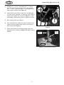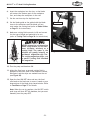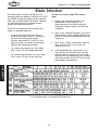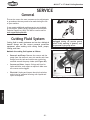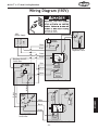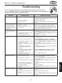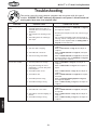
1
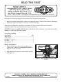
READ THIS FIRST Model M1014 ***IMPORTANT UPDATE*** Applies to Models Mfd. Since 11/14 and Owner's Manual Revised 11/10 Phone #: (360) 734-3482 • Tech Support: [email protected] • Web: www.shopfox.biz We made the following changes to this machine since the manual was printed: • • Motor now placed inside machine cabinet for shipping purposes. (Follow instructions for mounting.) Additional components added to inventory for motor mounting. Aside from the information contained in this update, all other content in the owner's manual is applicable and MUST be read and understood for your own safety. IMPORTANT: Keep this update with the owner's manual for future reference. If you have any further questions, contact our Technical Support. Inventory Update Description Qty V-Belt 3V270......................................................1 Hose Clamp 5⁄8"..................................................1 Hex Bolts 5⁄16"-18 x 1"...........................................4 Hex Nuts 5⁄16"-18.................................................2 Flat Washers 5⁄16"................................................2 Motor Installation 1. Remove motor from cabinet after installing filter screen (refer to Step 1 of Cutting Fluid System on Page 14 in owner's manual). 2. Slide motor mount plate into motor mount bracket (see Figure 1). Pulley Set Screw Motor Mount Plate Motor Mount Bracket Figure 1. Motor installed on motor mount bracket. COPYRIGHT © JANUARY, 2015 BY WOODSTOCK INTERNATIONAL, INC. #17105BL WARNING: NO PORTION OF THIS MANUAL MAY BE REPRODUCED IN ANY SHAPE OR FORM WITHOUT THE WRITTEN APPROVAL OF WOODSTOCK INTERNATIONAL, INC. Printed in China Model M1014 (Mfd. Since 11/14) 3. Thread (2) 5⁄16"-18 x 1" hex bolts with 5⁄16"-18 hex nuts into side of motor mount plate, then thread (2) 5⁄16"-18 x 1" hex bolts with 5⁄16" flat washers into motor mount bracket (see Figure 2). x2 4. Install V-belt onto pulleys, then use a straightedge to check pulley alignment. If pulleys are not aligned, loosen motor pulley set screw (see Figure 1 on previous page), adjust pulley, then re-tighten set screw. 5. Move coolant tank into cabinet. 6. Slide included hose clamp over end of coolant hose, insert hose onto coolant tank fitting, then tighten hose clamp (see Figure 3). 7. Follow instructions for mounting pulley cover and adjusting V-belt tension on Pages 15 & 18 of owner's manual. x2 Figure 2. Motor mounting fasteners installed. Coolant Hose Hose Clamp Fitting Figure 3. Coolant hose installed. -2- MODEL M1014 7" x 12" Metal Cutting Bandsaw INSTRUCTION MANUAL Phone: 1-360-734-3482 • On-Line Technical Support: [email protected] COPYRIGHT © JANUARY, 2005 BY WOODSTOCK INTERNATIONAL, INC. REVISED NOVEMBER, 2010 (TR) #6753CR WARNING: NO PORTION OF THIS MANUAL MAY BE REPRODUCED IN ANY SHAPE OR FORM WITHOUT THE WRITTEN APPROVAL OF WOODSTOCK INTERNATIONAL, INC. Printed in China This manual provides critical safety instructions on the proper setup, operation, maintenance, and service of this machine/tool. Save this document, refer to it often, and use it to instruct other operators. Failure to read, understand and follow the instructions in this manual may result in fire or serious personal injury—including amputation, electrocution, or death. The owner of this machine/tool is solely responsible for its safe use. This responsibility includes but is not limited to proper installation in a safe environment, personnel training and usage authorization, proper inspection and maintenance, manual availability and comprehension, application of safety devices, cutting/sanding/grinding tool integrity, and the usage of personal protective equipment. The manufacturer will not be held liable for injury or property damage from negligence, improper training, machine modifications or misuse. Some dust created by power sanding, sawing, grinding, drilling, and other construction activities contains chemicals known to the State of California to cause cancer, birth defects or other reproductive harm. Some examples of these chemicals are: • Lead from lead-based paints. • Crystalline silica from bricks, cement and other masonry products. • Arsenic and chromium from chemically-treated lumber. Your risk from these exposures varies, depending on how often you do this type of work. To reduce your exposure to these chemicals: Work in a well ventilated area, and work with approved safety equipment, such as those dust masks that are specially designed to filter out microscopic particles. SAFETY................................................4 Standard Machinery Safety Instructions....... 4 Additional Safety for Metal Cutting Bandsaws.6 Avoiding Potential Injuries....................... 7 WARRANTY......................................... 49 OPERATIONS MAINTENANCE ADJUSTMENTS..................................... 18 Belt Tension...................................... 18 Changing Cutting Speed........................ 19 Blade Tension.................................... 20 Blade Guides..................................... 21 SERVICE............................................. 30 General........................................... 30 Cutting Fluid System............................ 30 Blade Tracking................................... 31 Wiring Diagram (110V)......................... 33 Wiring Diagram (220V)......................... 34 Troubleshooting.................................. 35 Parts List.......................................... 38 Parts List.......................................... 40 Parts List.......................................... 42 Parts List.......................................... 44 Notes.............................................. 45 Notes.............................................. 46 SET UP SET UP............................................... 10 Unpacking........................................ 10 Items Needed for Set Up....................... 10 Inventory......................................... 11 Machine Placement............................. 12 Cleaning Machine................................ 12 Handle, Wheels, and Feet..................... 13 Cutting Fluid System............................ 14 Cast Iron Stop.................................... 14 Pulley Cover...................................... 15 Vertical Cutting Table.......................... 16 Shipping Strap and ON/OFF Switch . ........ 16 MAINTENANCE..................................... 28 General........................................... 28 Cleaning.......................................... 28 Lubrication....................................... 29 ELECTRICAL ELECTRICAL..........................................8 Circuit Requirements............................. 8 Grounding Requirements......................... 9 Extension Cords................................... 9 OPERATIONS....................................... 22 General........................................... 22 Operation......................................... 22 Blade Selection.................................. 24 Blade Changes................................... 25 Cutting Fluid..................................... 26 Feed Rate........................................ 27 SAFETY INTRODUCTION......................................2 Woodstock Technical Support................... 2 Specifications...................................... 2 Controls and Features............................ 3 INTRODUCTION Contents SERVICE PARTS INTRODUCTION M1014 7" x 12" Metal Cutting Bandsaw INTRODUCTION Woodstock Technical Support This machine has been specially designed to provide many years of trouble-free service. Close attention to detail, ruggedly built parts and a rigid quality control program assure safe and reliable operation. Woodstock International, Inc. is committed to customer satisfaction. Our intent with this manual is to include the basic information for safety, setup, operation, maintenance, and service of this product. We stand behind our machines! In the event that questions arise about your machine, please contact Woodstock International Technical Support at (360) 734-3482 or send e-mail to: tech-support@shopfox. biz. Our knowledgeable staff will help you troubleshoot problems and process warranty claims. If you need the latest edition of this manual, you can download it from http://www.shopfox.biz. If you have comments about this manual, please contact us at: Woodstock International, Inc. Attn: Technical Documentation Manager P.O. Box 2309 Bellingham, WA 98227 Email: [email protected] Specifications Bandsaw Motor Size.................... 1 HP, 110V/220V (Prewired 110V), 12A/6A, Single-Phase Motor Speed...................................................................................... 1,725 RPM Power Transfer................................................. V-Belt Drive and Worm-Gear Reduction Maximum Circular Capacity ..................................................................... 5" at 45° Maximum Rectangular Capacity ................................................ 4-3⁄4" x 4-1⁄2" at 45° Maximum Rectangular Capacity ..........................................................7" x 12" at 90° Maximum Circular Capacity .....................................................................7 " at 90° Coolant Capacity.................................................................................. 2-1⁄2 gal. Coolant Pump Motor................1/8 HP, 110V/220V (Prewired 110V), 0.6A/0.3A, Single-Phase Footprint............................................................................................. 13" x 38" Overall Dimensions............................................................... 48"L x 16"W x 37-5⁄8"H Blade Speeds........................................................................ 90, 135, 195, 255 FPM Blade Size.......................................................................................... 93" x 3⁄4" Bearings.......................................................... Permanently-Lubricated Ball Bearings Power Control...................................................................... Toggle ON/OFF Switch Net Weight...................................................................................... 275 lbs. -2- INTRODUCTION M1014 7" x 12" Metal Cutting Bandsaw Controls and Features B C D F A G E P H O I N M J L K Bandsaw controls and features. A. Blade Tension Knob—Allows you to quickly tension or de-tentsion the blade. I. B. Blade Guide Knob—Allows you to move and lock the blade guide in place. Drain and Chip Pan—Collects chips and cutting fluid, and directs fluid to the reservoir. J. Hydraulic Cylinder Feed Rate Dial—Allows you to adjust the bandsaw feed rate accurately. C. Cutting Fluid Flow Valve—Allows you to adjust the cutting fluid flow rate. K. Feed ON/OFF Valve—Toggles the headstock feed ON and OFF for operation or Service. D. Gear Box—Allows the motor to achieve a mechanical advantage when cutting. L. Cutting Fluid Pump ON/OFF Switch—Toggles power ON and OFF to the pump motor. E. Blade Guide/Chip Brush—Guides stop blade twist and brush removes chips from blade. M. Bandsaw ON/OFF Switch—Toggles power ON and OFF to the bandsaw motor. F. Pulley Cover—Covers the pulleys for safety. Open cover to make blade speed changes. N. Handle—Allows you to tilt the bandsaw and use the wheels to move the machine. G. Heavy Duty Motor—Dual voltage (prewired 110V), 1 HP motor drives the bandsaw wheels for smooth cutting. O. Vise Clamp Wheel—Allows you to quickly close and clamp the vise on the workpiece. H. Circuit Breaker—Protects the bandsaw motor and pump electrical system from overload. P. Blade Tension Gauge—Allows you to visually locate the correct blade tension. -3- M1014 7" x 12" Metal Cutting Bandsaw SAFETY SAFETY For Your Own Safety, Read Manual Before Operating Machine The purpose of safety symbols is to attract your attention to possible hazardous conditions. This manual uses a series of symbols and signal words intended to convey the level of importance of the safety messages. The progression of symbols is described below. Remember that safety messages by themselves do not eliminate danger and are not a substitute for proper accident prevention measures—this responsibility is ultimately up to the operator! Indicates an imminently hazardous situation which, if not avoided, WILL result in death or serious injury. Indicates a potentially hazardous situation which, if not avoided, COULD result in death or serious injury. Indicates a potentially hazardous situation which, if not avoided, MAY result in minor or moderate injury. NOTICE This symbol is used to alert the user to useful information about proper operation of the equipment, and/or a situation that may cause damage to the machinery. Standard Machinery Safety Instructions OWNER’S MANUAL. Read and understand this owner’s manual BEFORE using machine. Untrained users can be seriously hurt. HEARING PROTECTION. Always wear hearing protection when operating or observing loud machinery. Extended exposure to this noise without hearing protection can cause permanent hearing loss. EYE PROTECTION. Always wear ANSI-approved safety glasses or a face shield when operating or observing machinery to reduce the risk of eye injury or blindness from flying particles. Everyday eyeglasses are not approved safety glasses. MENTAL ALERTNESS. Be mentally alert when running machinery. Never operate under the influence of drugs or alcohol, when tired, or when distracted. HAZARDOUS DUST. Dust created while using machinery may cause cancer, birth defects, or long-term respiratory damage. Be aware of dust hazards associated with workpiece materials, and always wear a NIOSH-approved respirator to reduce your risk. DISCONNECTING POWER SUPPLY. Always disconnect machine from power supply before servicing, adjusting, or changing cutting tools (bits, blades, cutters, etc.). Make sure switch is in OFF position before reconnecting to avoid an unexpected or unintentional start. WEARING PROPER APPAREL. Do not wear clothing, apparel, or jewelry that can become entangled in moving parts. Always tie back or cover long hair. Wear non-slip footwear to avoid accidental slips which could cause a loss of workpiece control. DANGEROUS ENVIRONMENTS. Do not use machinery in wet or rainy locations, cluttered areas, around flammables, or in poorly-lit areas. Keep work area clean, dry, and welllighted to minimize risk of injury. -4- M1014 7" x 12" Metal Cutting Bandsaw STABLE MACHINE. Unexpected movement during operations greatly increases the risk of injury and loss of control. Verify machines are stable/secure and mobile bases (if used) are locked before starting. FORCING MACHINERY. Do not force machine. It will do the job safer and better at the rate for which it was designed. ONLY USE AS INTENDED. Only use machine for its intended purpose. Never modify or alter machine for a purpose not intended by the manufacturer or serious injury may result! AWKWARD POSITIONS. Keep proper footing and balance at all times when operating machine. Do not overreach! Avoid awkward hand positions that make workpiece control difficult or increase the risk of accidental injury. USE RECOMMENDED ACCESSORIES. Consult this owner’s manual or the manufacturer for recommended accessories. Using improper accessories will increase the risk of serious injury. UNATTENDED OPERATION. Never leave machine running while unattended. Turn machine off and ensure all moving parts completely stop before walking away. CHILDREN & BYSTANDERS. Keep children and bystanders a safe distance away from work area. Stop using machine if children or bystanders become a distraction. MAINTAIN WITH CARE. Follow all maintenance instructions and lubrication schedules to keep machine in good working condition. An improperly maintained machine may increase the risk of serious injury. REMOVE ADJUSTING TOOLS. Never leave adjustment tools, chuck keys, wrenches, etc. in or on machine—especially near moving parts. Verify removal before starting! CHECK DAMAGED PARTS. Regularly inspect machine for damaged parts, loose bolts, mis-adjusted or mis-aligned parts, binding, or any other conditions that may affect safe operation. Always repair or replace damaged parts, wires, cords, or plugs before operating machine. SECURING WORKPIECE. When required, use clamps or vises to secure workpiece. A secured workpiece protects hands and frees both of them to operate the machine. FEED DIRECTION. Unless otherwise noted, feed work against the rotation of blades or cutters. Feeding in the same direction of rotation may pull your hand into the cut. MAINTAIN POWER CORDS. When disconnecting cord-connected machines from power, grab and pull the plug—NOT the cord. Pulling the cord may damage the wires inside. Do not handle the cord/plug with wet hands. Avoid cord damage by keeping it away from heated surfaces, high traffic areas, harsh chemicals, and wet or damp locations. GUARDS & COVERS. Guards and covers can protect you from accidental contact with moving parts or flying debris. Make sure they are properly installed, undamaged, and working correctly before using machine. EXPERIENCING DIFFICULTIES. If at any time you are experiencing difficulties performing the intended operation, stop using the machine! Contact our Technical Support for help at (360) 734-3482. NEVER STAND ON MACHINE. Serious injury or accidental contact with cutting tool may occur if machine is tipped. Machine may be damaged. -5- SAFETY APPROVED OPERATION. Untrained operators can be seriously hurt by machinery. Only allow trained or properly supervised people to use machine. When machine is not being used, disconnect power, remove switch keys, or lock-out machine to prevent unauthorized use—especially around children. Make workshop kid proof! M1014 7" x 12" Metal Cutting Bandsaw SAFETY Additional Safety for Metal Bandsaws Use this and other machinery with caution and respect. Always consider safety first, as it applies to your individual working conditions. No list of safety guidelines can be complete—every shop environment is different. Failure to follow guidelines could result in serious personal injury, damage to equipment or poor work results. READ and understand this entire instruction manual before using this machine. Serious personal injury may occur if safety and operational information is not understood and followed. 1. SAFETY GUARDS. DO NOT operate bandsaw without wheel covers, pulley covers, or blade guards in place. 2. SERVICE PREPARATION. Turn OFF and unplug machine before blade replacement, machine adjustments, and maintenance are done. Allow all moving parts to come to a complete stop before doing any of the above. 3. SAFETY TOOLS. Use push sticks or other safety devises whenever possible, especially when the bandsaw is set up for vertical cutting. 4. KEEPING HANDS CLEAR. Never reach under table, in the blade path, or around the blade guides while blade is in motion. 5. FURTHER INFORMATION. If at any time you are experiencing difficulties performing the intended operation, stop using the machine! Then contact our technical support department or ask a qualified expert how the operation should be performed. 6. SHOP SAFETY. Habits—good and bad—are hard to break. Develop good habits in your shop and safety will become second-nature to you. 7. WORKPIECE REMOVAL. Never back the workpiece from the blade when the bandsaw is set up for vertical cutting and while the bandsaw blade is in motion. Turn OFF machine and wait for blade to come to a complete stop before backing workpiece out. 8. MANUAL INSPECTIONS. Unplug the machine and manually test blade tracking and tension before starting the machine. Blades that are loose or not tracking correctly can come off and cause serious personal injury. 9. SUPPORTING LONG WORKPIECECS. Long workpieces should be well supported at both ends with extension tables when cuts are made. Otherwise, after a cut is made, the cut piece may fall to the floor and the stock may tilt out of the vise and break the blade. 10.SAFELY USING CUTTING FLUIDS. Make sure you know what type of metal and cutting fluid you will be exposed to and how to avoid contamination. Be aware that certain metal shavings and cutting fluids may cause an allergic reaction in people and animals, especially when cutting fumes can be inhaled. -6- M1014 7" x 12" Metal Cutting Bandsaw Avoiding Potential Injuries SAFETY Figure 3. Never attempt to freehand cut. Figure 6. Always use the table for freehand cutting and keep fingers clear of blade. Figure 4. Never start the saw with the blade resting on the workpiece. Figure 7. Always start the saw with the blade clear of the workpiece. Figure 5. Never hold the workpiece by hand. Figure 8. Always use the vise to hold workpiece. -7- M1014 7" x 12" Metal Cutting Bandsaw ELECTRICAL Circuit Requirements ELECTRICAL This machine must be connected to the correct size and type of power supply circuit, or fire or electrical damage may occur. Read through this section to determine if an adequate power supply circuit is available. If a correct circuit is not available, a qualified electrician MUST install one before you can connect the machine to power. The machine must be properly set up before it is safe to operate. DO NOT connect this machine to the power source until instructed to do later in this manual. A power supply circuit includes all electrical equipment between the breaker box or fuse panel in the building and the machine. The power supply circuit used for this machine must be sized to safely handle the fullload current drawn from the machine for an extended period of time. (If this machine is connected to a circuit protected by fuses, use a time delay fuse marked D.) Full-Load Current Rating The full-load current rating is the amperage a machine draws at 100% of the rated output power. On machines with multiple motors, this is the amperage drawn by the largest motor or sum of all motors and electrical devices that might operate at one time during normal operations. Full-Load Current Rating at 110V.................12.6 Amps Full-Load Current Rating at 220V.................. 6.3 Amps Circuit Requirements for 110V (Prewired) This machine is prewired to operate on a 110V power supply circuit that has a verified ground and meets the following requirements: Circuit Type................ 110V/120V, 60 Hz, Single-Phase Circuit Size.............................................. 20 Amps Plug/Receptacle..................................... NEMA 5-20 Circuit Requirements for 220V This machine can be converted to operate on a 220V power supply (details about voltage conversion can be found later in this manual). The 220V power supply circuit must have a verified ground and meet the requirements that follow: Circuit Type................220V/240V, 60 Hz, Single-Phase Circuit Size.............................................. 15 Amps Plug/Receptacle..................................... NEMA 6-15 -8- Incorrectly wiring or grounding this machine can cause electrocution, fire, or machine damage. To reduce this risk, only a qualified electrician or service personnel should do any required electrical work for this machine. NOTICE The circuit requirements listed in this manual apply to a dedicated circuit— where only one machine will be running at a time. If this machine will be connected to a shared circuit where multiple machines will be running at the same time, consult a qualified electrician to ensure that the circuit is properly sized for safe operation. M1014 7" x 12" Metal Cutting Bandsaw Grounding Requirements This machine MUST be grounded. In the event of certain types of malfunctions or breakdowns, grounding provides a path of least resistance for electric current to travel—in order to reduce the risk of electric shock. Check with a qualified electrician or service personnel if you do not understand these grounding requirements, or if you are in doubt about whether the tool is properly grounded. If you ever notice that a cord or plug is damaged or worn, disconnect it from power, and immediately replace it with a new one. 110V Hot Neutral 5-20 PLUG Grounding Prong Figure 9. NEMA 5-20 plug & receptacle. For 110V Connection (Prewired) This machine is equipped with a power cord that has an equipment-grounding wire and NEMA 5-15 grounding plug. The plug must only be inserted into a matching receptacle (see Figure) that is properly installed and grounded in accordance with local codes and ordinances. GROUNDED 5-20 RECEPTACLE 220V GROUNDED 6-15 RECEPTACLE Current Carrying Prongs 6-15 PLUG For 220V Connection (Must be Rewired) A NEMA 6-15 plug has a grounding prong that must be attached to the equipment-grounding wire inside the included power cord. The plug must only be inserted into a matching receptacle (see Figure) that is properly installed and grounded in accordance with all local codes and ordinances. Extension Cords We do not recommend using an extension cord with this machine. Extension cords cause voltage drop, which may damage electrical components and shorten motor life. Voltage drop increases with longer extension cords and the gauge smaller gauge sizes (higher gauge numbers indicate smaller sizes). Any extension cord used with this machine must contain a ground wire, match the required plug and receptacle, and meet the following requirements: Minimum Gauge Size at 220V....................... 14 AWG Maximum Length (Shorter is Better).................50 ft. -9- Grounding Prong Figure 10. NEMA 6-15 plug & receptacle. DO NOT modify the provided plug or use an adapter if the plug will not fit your receptacle. This is an indication that your power supply circuit does meet the requirements for the machine; have an electrician install the correct power supply circuit. If the machine must be reconnected for use on a different type of electric circuit, the reconnection should be made by a qualified electrician or service personnel; after reconnection, the machine must comply with all local codes and ordinances. ELECTRICAL Improper connection of the equipment-grounding wire will increase the risk of electric shock. The wire with green insulation (with/without yellow stripes) is the equipmentgrounding wire. If repair or replacement of the power cord or plug is necessary, do not connect the equipmentgrounding wire to a live (current carrying) terminal. The machine must be properly set up before it is safe to operate. DO NOT connect this machine to the power source until instructed to do later in this manual. M1014 7" x 12" Metal Cutting Bandsaw SET UP Unpacking This machine has been carefully packaged for safe transportation. If you notice the machine has been damaged during shipping, please contact your authorized Shop Fox dealer immediately. Items Needed for Set Up SET UP The following items are needed, but not included, to set up your machine: • An Assistant. • Phillips Screwdriver #2. • Standard Screwdriver #2. • Hex Wrench 6mm. • Open-End Wrench 6mm, 12mm, 14mm, 19mm. • Open-End Wrench 3/8", 7/16", 1/2." READ and understand this entire instruction manual before using this machine. Serious personal injury may occur if safety and operational information is not understood and followed. DO NOT risk your safety by not reading! KEEP the power cord UNPLUGGED during assembly or adjustment tasks! Otherwise, serious personal injury to you or others may occur! Seek assistance when lifting the machine from the box it was shipped in. The SHOP FOX® Model M1014 is a heavy machine. -10- M1014 7" x 12" Metal Cutting Bandsaw Inventory The following is a description of the main components shipped with the SHOP FOX® Model M1014. Lay the components out to inventory them. SUFFOCATION HAZARD! Immediately discard all plastic bags and packing materials to eliminate choking/suffocation hazards for children and animals. SET UP Box Contents (Figure 11) Qty. A. Pulley Cover.................................................2 B. Vertical Work Table........................................1 C. Table Bracket...............................................1 D. Handle........................................................1 E. Wheels.......................................................2 F. Collar.........................................................1 G. Axle...........................................................1 H. Work Stop Rod..............................................1 I. Work Stop....................................................1 J. Leveling Feet with Hex Nuts..............................2 K. Chip Screen..................................................1 L. Bolt Bag......................................................1 —Flat Washers 3⁄8" (Leveling Feet)......................2 —Hex Nuts 3⁄8"-16 (Leveling Feet).......................2 —Cotter Pins 3 x 25mm (Wheels)........................2 —Hex Bolts 5⁄16"-18 x 11⁄2" (Handle)....................4 —Flat Head Screw 1⁄4"-20 x 1⁄2" (Table).................1 —Hex Nut 1⁄4" x 20 (Table)................................1 —Phillips Head Screws 1⁄4"-20 x 5⁄8" (Pulley Cover)...2 If any parts appear to be missing, examine the packaging carefully to be sure those parts are not among the packing materials. If any parts are missing, find the part number in the back of this manual and contact Woodstock International, Inc. at 360-7343482 or at [email protected] A B C D E H F G K J Figure 11. Inventory. -11- I L M1014 7" x 12" Metal Cutting Bandsaw SET UP Machine Placement • Floor Load: This machine distributes a heavy load in a small footprint. Some residential floors may require additional bracing to support both machine and operator. • Working Clearances: Consider existing and anticipated needs, size of material to be processed through the machine, and space for auxiliary stands, work tables or other machinery when establishing a location for your Machine Type. • Lighting: Lighting should be bright enough to eliminate shadow and prevent eye strain. • Electrical: Electrical circuits must be dedicated or large enough to handle amperage requirements. Outlets must be located near each machine, so power or extension cords are clear of high-traffic areas. Follow local electrical codes for proper installation of new lighting, outlets, or circuits. Cleaning Machine The table and other unpainted parts of your bandsaw are coated with a waxy grease that protects them from corrosion during shipment. Clean this grease off with a solvent cleaner or citrus-based degreaser. DO NOT use chlorinebased solvents such as brake parts cleaner or acetone—if you happen to splash some onto a painted surface, you will ruin the finish. NEVER use gasoline or other petroleum-based solvents to clean with. Most have low flash points, which make them extremely flammable. A risk of explosion and burning exists if these products are used. Serious personal injury may occur if this warning is ignored! USE helpers or power lifting equipment to lift this Machine Name. Otherwise, serious personal injury may occur. ALWAYS work in wellventilated areas far from possible ignition sources when using solvents to clean machinery. Many solvents are toxic when inhaled or ingested. Use care when disposing of waste rags and towels to be sure they DO NOT create fire or environmental hazards. MAKE your shop “child safe.” Ensure that your workplace is inaccessible to children by closing and locking all entrances when you are away. NEVER allow untrained visitors in your shop when assembling, adjusting or operating equipment. -12- M1014 7" x 12" Metal Cutting Bandsaw Handle, Wheels, and Feet Get assistance when lifting this machine. Otherwise, you can severely injure yourself! To install the handle, wheels, and feet, do these steps: 1. With the help of an assistant, support the bandsaw on wooden blocks approximately 4" from the ground so you have room to install the handle, wheels, and feet. Hex Bolt and Washer Figure 12. Installed handle. 2. Align the handle mounting holes with the bandsaw holes, and install the 5/16"-18 x 1-1/4" hex bolts, washers, and nuts (see Figure 12). SET UP 3. Insert the axle into the cabinet, and slide the wheels onto the axles. 4. Slide the two 5/8" flat washers onto the axles, and install the two cotter pins (see Figure 13). 5. Thread one 3/8"-18 hex nut and install one 3/8" washer onto each threaded foot shaft (see Figure 14). 6. Thread the foot shafts into the underside of the bandsaw cabinet (see Figure 14). 7. With the help of an assistant, remove the bandsaw from the blocks. 8. Turn the feet until the bandsaw is level, and tighten the hex nut to lock the feet in place. Figure 13. Installed wheel. Flat Washer Here Hex Nut Here Figure 14. Installed feet. -13- M1014 7" x 12" Metal Cutting Bandsaw Cutting Fluid System This bandsaw has a built-in cutting fluid system that prolongs the life of your bandsaw blades and produces smoother cuts at a lower temperature. Refer to Cutting Fluid on Page 26 for fluid choice and safety precautions. To set up the cutting fluid system, do these steps: Filter Screen 1. Place the filter screen dome-side up as shown in Figure 15 in the bandsaw catch pan. 2. Inspect and remove any foreign material that may have fallen inside the reservoir during shipping. SET UP 3. Make sure the drain tube points toward the reservoir intake screen, and that all tube connections are tight and will not leak (see Figure 16). 4. Make sure the waterproof rubber switch boot is installed on the pump ON/OFF toggle switch (Figure 16), and that the toggle switch is in the down position. Figure 15. Installed drain screen. Drain Tube Note: DO NOT plug in the bandsaw at this time to prime the pump. Priming will be done in the Operations section. 5. Fill the reservoir with 2-1/2 gallons of your chosen cutting fluid solution. NOTICE: NEVER operate the pump with the reservoir below the low mark (Figure 16), or the pump can be destroyed! High Low Pump Toggle Switch Figure 16. Correctly filled tank ready to be pumped. Cast Iron Stop The cast iron stop allows you to repeat many cuts at the same length. To install the cast iron stop, do these steps: Stop Rod and Hex Bolt Thumbscrew 1. Insert the stop rod approximately 3/4" into the saw until the end of the rod is just flush with the inside casting surface (see Figure 17). 2. Use a 12mm wrench, and tighten the hex bolt (see Figure 17). Cast Iron Stop 3. Slide the cast iron stop onto the stop rod and tighten the thumb screw. Figure 17. Installing the cast iron stop. -14- M1014 7" x 12" Metal Cutting Bandsaw Pulley Cover When opened, the pulley cover gives you the ability to change the pulley ratio so the bandsaw can cut at one of four speeds. ENTANGLEMENT MAKE SURE the unplugged before Otherwise, severe occur. HAZARD! bandsaw is proceeding! injury may To install the pulley cover, do these steps: 1. UNPLUG THE BANDSAW POWER CORD! Figure 18. Installing the bearing guard. 2. Snap the bearing guard into the pulley cover (see Figure 18). SET UP 3. Position and rotate the pulley cover mounting plate onto the motor as shown in Figure 19. 4. Install the pulley cover mounting screws, as shown in Figure 20. 5. Make sure the pulley ratio will produce the speed that you want. • If the speed needs to be changed, complete the Changing Cutting Speed procedure on Page 19. 6. Install the belt and make sure it has 1/4" deflection when pressed. Figure 19. Positioning the pulley cover. • If the belt is out of adjustment, complete the Belt Tension procedure on Page 18. Figure 20. Securing the pulley cover. -15- M1014 7" x 12" Metal Cutting Bandsaw Shipping Strap and ON/OFF Switch To ensure that your bandsaw arrives to you without damage to the hinge system, a shipping strap was installed. After shipping strap removal, adjust the headstock-stop bolt so the bandsaw ON/OFF switch is not damaged by the headstock. Note: Keep this shipping strap in the event that you must transport the bandsaw. Shipping Strap To remove the shipping strap, do these steps: 1. Turn the feed lever OFF (Figure 22) so the headstock is supported when the shipping strap is removed. SET UP 2. Remove the ON/OFF switch push strap and save it for reinstallation later (see Figure 21). Stop Bolt ON/OFF Switch Push Strap Figure 21. Shipping strap location. 3. Using a screwdriver and a 14mm wrench, remove the screw, headstock stop bolt, and shipping strap. 4. Reinstall the headstock stop bolt to the lowest setting, and engage the feed lever so the headstock settles naturally to the lowest position. 5. Rotate the stop bolt counterclockwise so the headstock is slightly supported by the stop bolt, and tighten the jam nut. 6. With the bandsaw unplugged, flip the ON/OFF switch to the ON position. 7. Reinstall the ON/OFF switch push strap so it has just pushed the toggle switch downward to the OFF position, but does not force the toggle past the OFF position and tear the rubber boot or damage the switch. Figure 22. Feed lever in the locked position. Vertical Cutting Table If you install the vertical cutting table, this bandsaw can be set up and used as a vertical-cutting bandsaw. To install the vertical cutting table, do these steps: 1. MAKE SURE THE POWER CORD IS UNPLUGGED! 2. Raise the bandsaw headstock to the vertical position, and with the feed lever, lock the headstock in place (see Figure 22). 3. Remove the screws and stop plate as shown in Figure 23. -16- Figure 23. Removing the stop plate. M1014 7" x 12" Metal Cutting Bandsaw 4. Position and install the vertical cutting table with the two stop plate mounting screws as shown in Figure 24). 5. Use a 14 mm wrench to loosen the blade guide lock bolt and install the table support as shown in Figure 25. 6. Place a machinist's square on the table as shown in Figure 26, and make sure that the table and blade are square with each other. • If the table and blade are out of square, adjust the table support bracket. Figure 24. Installing the table. SET UP Figure 25. Installing the table support. Figure 26. Checking table-to-blade squareness. -17- M1014 7" x 12" Metal Cutting Bandsaw ADJUSTMENTS Belt Tension During the life of your bandsaw, you will find it necessary to change the location of the belt so the saw blade can cut at a different speed. To change the belt location you must use the belt adjustment mechanism to move the motor, which loosens or tightens the belt. To adjust the belt, do these steps: 1. UNPLUG THE BANDSAW POWER CORD! 2. Open the pulley cover and determine if the belt must be loosened or tightened. The belt should only have 1/4" of deflection when the belt is pressed in the middle. 3. Use a 12mm wrench and loosen the two slide bolts and both jack-bolt and jam nuts shown in Figure 27. • If the belt needs to be tightened, turn the lower jack bolt counterclockwise until only a few threads are holding the bolt in place, and then turn the upper jack bolt clockwise until the belt has 1/4" of deflection. • If the belt needs to be loosened, turn the upper jack bolt counterclockwise until only a few threads are holding the bolt in place, and then turn the lower jack bolt clockwise until the belt has 1/4" of deflection. DO NOT investigate problems or adjust the bandsaw while it is running. Wait until the machine is turned off, unplugged and all working parts have come to a complete stop before proceeding! Lower Jack Bolt and Jam Nut Upper Jack Bolt and Jam Nut Slide Bolts MAINTENANCE 4. Tighten both jam nuts and both slide bolts. 5. Close the pulley cover. Figure 27. Belt adjustment mechanism. -18- M1014 7" x 12" Metal Cutting Bandsaw Changing Cutting Speed Along with the correct blade selection and feed rate, the correct pulley ratio must be selected to produce the best cutting speed. With all settings correct, the metal chips should be curly and silvery, they should not be overheated and blue, or thin and powdery. To change the cutting speed, do these steps: 1. UNPLUG THE BANDSAW POWER CORD! 2. Refer to Figure 28 and match the workpiece material with the suggested blade speed, and then find the correct pulley ratio to get that blade speed. 3. Open the pulley cover and loosen the belt tension. Refer to Belt Tension on Page 18 for any details. 4. Roll the belt into the new pulley grooves. 5. Adjust the belt tension, and close the pulley cover. Note: These suggested blade speeds are an average for both High Carbon Blades and Bi-Metal Blades. Refer to your saw blade manufac- turer for exact speeds. Workpiece Material Tool Steel Stainless Steel Alloy Steel Bearing Bronze High Carbon Steel Medium Carbon Steel Hard Brass Hard Bronze Low Carbon Steel Soft Brass Copper Aluminum Plastics Speed in FPM 90 90 90 90 135 135,195 195 195 195 195 255 255 255 Note: Feet Per Minunite is (FPM). 90 135 195 255 Motor Pulley Wheel Pulley -19- MAINTENANCE Figure 28. Blade cutting speed chart. M1014 7" x 12" Metal Cutting Bandsaw Blade Tension If blade tension is set incorrectly, the blade can fracture and break, become belled, or slip off of the bandsaw. You must make sure the blade tension is set in the correct range to prevent these problems. To set the blade tension, do these steps: 1. Make sure the blade tracking is set correctly. Refer to Blade Tracking on Page 31 for details. 2. Raise the headstock to the vertical position and close the feed valve to lock the headstock in place (see Figure 46 on Page 31). 3. Open the blade cover and remove the blade guides (see Figure 29). 4. Turn the blade tension knob until the blade is snug and the blade tension notch indicates "medium," which is in the green area shown in Figures 30 and 31. Figure 29. Bandsaw ready for blade tracking. 5. Reinstall the blade guides and adjust as outlined in the Blade Guide instructions on Page 21. Blade Tension Knob 6. Close the blade guard. MAINTENANCE Blade Tension Scale Figure 30. Blade tension adjustment knob. Blade Tension Notch Figure 31. Blade tension scale. -20- M1014 7" x 12" Metal Cutting Bandsaw Blade Guides The blade guide side bearings support the blade so the blade will enter the workpiece perpendicular to the table surface (see Figure 32). The blade guide support bearings prevent blade twist by stopping the blade from being pushed back during a cut. Both adjustments are the most critical saw adjustments. UNPLUG the bandsaw power cord, and NEVER adjust the blade guides while the saw blade is moving! To adjust the guide bearings, do these steps: Note: Make sure the blade is tensioned and tracks correctly before you adjust the blade guide bearings. Refer to Blade Tension or Blade Tracking on Pages 20 and 31 for further instructions. Guide Blade Guide Support Bearing Bearing Adjustment Cap Screw Side Bearing Eccentric and Jam Nut Blade Guide Side Bearing Figure 32. Blade guide adjustment locations. Side Bearing Eccentric and Jam Nut Guide Bearing Adjustment Cap Screw 1. UNPLUG THE BANDSAW POWER CORD! 2. Let the bandsaw headstock park in the full down position. 3. Using a 6mm hex wrench, loosen the guide bearing adjustment cap screw (see Figures 32 and 33). Figure 33. Blade guide location. 4. Adjust the blade guide housing so the support bearing rests against the rear of the blade (see Figure 32). 6. Using a 14mm wrench, loosen the outer side bearing eccentric jam nuts. Note: The inner side bearings are not on eccentric shafts and cannot be adjusted. 7. Using a 6mm wrench, rotate the side bearing eccentrics (Figure 33) until the bearings hold the blade perpendicular to the table surface and have a bearing-to-blade clearance of 0.000" to 0.001". The bearings must not pinch the blade. Note: To make sure the blade is perpendicular to the table, use a standard machinist's square. 8. Tighten the jam nuts and slide the blade guide close to the workpiece so the blade is supported and will not twist during the cut (see Figure 34). -21- Lock Knob Figure 34. Blade guide position lock knob. MAINTENANCE 5. Tighten the cap screw. M1014 7" x 12" Metal Cutting Bandsaw OPERATIONS General The Model M1014 will perform many types of operations that are beyond the scope of this manual. Many of these operations can be dangerous or deadly if performed incorrectly. The instructions in this section are written with the understanding that the operator has the necessary knowledge and skills to operate this machine. If at any time you are experiencing difficulties performing any operation, stop using the machine! If you are an inexperienced operator, we strongly recommend that you read books, trade articles, or seek training from an experienced bandsaw operator before performing any unfamiliar operations. Above all, your safety should come first! READ and understand this entire instruction manual before using this machine. Serious personal injury may occur if safety and operational information is not understood and followed. DO NOT risk your safety by not reading! Operation Before making cuts to the workpiece, it is important that all safety precautions and bandsaw adjustments are addressed. For vertical cutting, refer to Vertical Cutting Table on Page 16 for table installation steps. For basic cutting operations, do these steps: MAINTENANCE 1. Check oil level and top it off if required (refer to Lubrication on Page 29 for instructions). Always wear safety glasses when operating the 7" x 12" Metal Cutting Bandsaw. Failure to comply may result in serious personal injury. 2. Select and install the required blade (refer to Blade Selection on Page 24 for blade TPI). 3. Select the required cutting speed, (refer to Changing Cutting Speed on Page 19 for instructions). 4. Make sure cutting fluid reservoir is full and the fluid is correct for the type of blade and material to be cut (refer to Cutting Fluid on Page 26 for instructions). 5. Raise and lock the headstock, so the blade is approximately 3" from the workpiece, and open the vise to accept the workpiece. NOTICE: NEVER let the saw blade rest on the workpiece without the saw running. Otherwise, you will permanently damage the saw blade! -22- DO NOT investigate problems or adjust the Bandsaw while it is running. Wait until the machine is turned OFF, unplugged, and all working parts have come to a complete stop before proceeding! M1014 7" x 12" Metal Cutting Bandsaw 6. Insert the workpiece into the vise, so the blade will contact the flattest part of the workpiece first, and clamp the workpiece in the vise. 7. Set the cast iron stop for duplicate cuts. 8. Set the blade guide so the guides hold the blade close to the workpiece and the blade will not twist under the cutting load (refer to Blade Guides on Page 21 for instructions). Flow Lever 9. Make sure cutting fluid reservoir is full and correct for the type of blade and material to be cut, (refer to Cutting Fluid on Page 26 for instructions). 10.Turn the pump and bandsaw ON. 11.Adjust the flow lever so enough cutting fluid is pumped so that both sides of the blade are cooled, lubricated, and the chips are washed from the cut (see Figure 35). 12.Open the feed ON/OFF valve and turn the feed rate knob so the feed rate is correct, based on your observations of the blade chip characteristics. Refer to Feed Rate on Page 27 for details. Note: When the cut is complete, the ON/OFF switch push strap will shut OFF the bandsaw, but you must manually turn the pump OFF. -23- Figure 35. Lubricator flow control lever. OPERATIONS NEVER attempt to cut Magnesium when using soluble oils or emulsions (oil-water solutions) as a cutting fluid! The water in the solution will greatly intensify an accidental magnesium-chip fire. For cutting magnesium alloys, use a specific cutting fluid intended for magnesium. M1014 7" x 12" Metal Cutting Bandsaw Blade Selection The chart below is a basic starting point for choosing blade type based on teeth per inch (TPI) for variable tooth pitch blades and for standard raker type bi-metal blades/HSS blades. However, for exact specifications of bandsaw blades, contact the blade manufacturer. There are three general rules of thumb with respect to bandsaw blade use. • • For a slower but smoother cut, use a blade with a lower TPI and a lower feed rate. 3. Refer to the "Shape" of metal and "Material Type" columns and find the shape and material to be cut. 4. In the applicable row, read across to the right and find the box where the row and column intersect. Listed in the box is the minimum TPI recommended for the variable tooth pitch blades; and the TPI for bi-metal raker blades in parentheses. OPERATIONS For a faster but rougher cut, use a blade with a lower TPI and a higher feed rate. 1. Measure the material thickness. This measurement is the length of cut taken from where the tooth enters the workpiece, sweeps through, and exits the workpiece. 2. Refer to the "Material Thickness" row of the blade selection chart in Figure 36 and read across to find your workpiece thickness you need to cut. At least three teeth must contact the metal at any phase of the cut. Otherwise the teeth can load up with metal, fracture, and break off. If the TPI is too high, the teeth can load up with material and overheat damaging the blade. • To select the correct blade TPI do these steps: Figure 36. Blade selection chart. Note: The TPI numbers in parentheses apply to bi-metal/HSS blades only. -24- M1014 7" x 12" Metal Cutting Bandsaw Blade Changes You will find it necessary to change blades depending on the type of material to be cut. Knowing how to correctly select, change, track, and tension the blade will extend the life of your bandsaw and blades. UNPLUG the bandsaw power cord, and NEVER work around the blade or adjust the table while the saw blade is moving! To change the bandsaw blade, do these steps: 1. UNPLUG THE BANDSAW POWER CORD! Figure 37. Stopping the feed cylinder. 2. Raise the headstock to the vertical position and close the feed valve to lock the headstock in place (see Figure 37). 3. Open the blade guard door, and use a screwdriver to remove the blade guide blade guard and the wire wheel brush (see Figure 38). Guard Screw Brush Screw CAUTION: WEAR LEATHER GLOVES when changing the 4. Put on thick leather gloves. 5. Loosen the blade tension knob, note the direction of teeth, and remove the blade from the wheels and the blade guides (see Figure 39). Figure 38. Blade accessories. Blade Tension Knob 6. Wipe the new blade with oil, and insert it into the blade guides with the teeth down. 7. While keeping the blade in the guides, slide the blade onto the lower wheel and then the upper wheel. 8. Carefully make sure that the blade is seated on the wheels correctly and re-tension the blade. Refer to Blade Tension on Page 20 for instructions. Teeth Point Down 9. Reinstall the blade guide blade guard and the wire wheel so the blade sinks into wire wheel center line. 10.Close the blade guard door and check and set the blade tracking. Refer to Blade Tracking on Page 31 for instructions. 11.Check and readjust the blade guides if required. Refer to Blade Guides on Page 21 for instructions. -25- Figure 39. Open blade guard door. OPERATIONS bandsaw blade. Otherwise, you may seriously cut your hand! M1014 7" x 12" Metal Cutting Bandsaw Cutting Fluid While simple in concept and function, many issues must be taken into account and addressed to find and use the correct cutting fluid. Always follow all product warnings and contact the fluid manufacturer for unanswered questions. BIOLOGICAL and POISON HAZARD! OPERATIONS Use the selections below to choose the appropriate cutting fluids: • For cutting low alloy, low carbon, and general-purpose category metals with a bi-metal blade—use a water soluble cutting fluid. • For cutting stainless steels, high carbon, and high alloy metals, brass, copper and mild steels—use "Neat Cutting Oil" (commonly undiluted mineral oils) that have extreme pressure additives (EP additives). • For cutting cast iron, cutting fluid is not recommended. NEVER attempt to cut magnesium when using soluble oils or emulsions (oil-water solutions) as a cutting fluid! The water in the solution will greatly intensify an accidental magnesium-chip fire. For cutting magnesium alloys, use a specific cutting fluid intended for magnesium. Remember: Too much flow at the cutting fluid nozzle will make a mess and can make the work area unsafe; and not enough fluid at the cut will heat the blade, causing the blade teeth to load up and break. Adjust the flow rate lever so the coolant will cool and lubricate the blade, and flush the chips away so they do not stick to the blade. If the chips build up on the blade, eventually they will bind and skid in the next cut, breaking blade teeth, and damaging the bandsaw wheels. -26- The reservoir on this machine is designed to store cutting fluid. During storage some fluids grow dangerous microbes, or due to the collection of toxic metal chips in the fluid, the fluid can become a potent and extremely poisonous solution to humans and animals. USE the correct personal protection equipment when handling cutting fluids to prevent infections and poisoning. FOLLOW federal, state, and the fluid manufacturer requirements to properly dispose of cutting fluid when it becomes unsafe. M1014 7" x 12" Metal Cutting Bandsaw Feed Rate The speed at which the saw blade will cut through a workpiece is controlled by blade type, feed rate, and feed pressure. Note: If a lubricant is used on the cut, the feed rate can be increased by approximately 15%. To set the feed rate, do these steps: Feed ON/ OFF Lever and Valve 1. Raise the headstock. 2. Using a 14mm wrench, adjust the feed pressure tension spring so the spring coils are not in tension, but the spring is still held firmly in place (see Figure 41). Note: This spring adjustment is an initial setting and depending on cutting circumstances, you will have to fine-tune the feed pressure with this adjustment. Increasing the spring tension will reduce the feed pressure. Feed Rate Dial and Valve Figure 40. Feed rate controls. Feed Pressure Tension Spring Adjustment 3. Clamp the workpiece in the table vise. 5. With the correct saw blade and blade speed selected, turn the saw and lubricant pump ON. 6. Slowly rotate the feed rate dial to a conservative feed rate until the saw begins to cut the workpiece (see Figure 41). 7. Observe the chips that exit the cut, and increase or decrease the feed rate according to the chip characteristics (see Figure 42). Feed ON/OFF Lever Figure 41. Bandsaw operating and starting feed before blade contacts workpiece. Chips are width of tooth, thin and curled, and silvery: Optimum speed and feed rate. Chips are silvery, thin, small, or powdery: Reduce cutting speed or increase feed rate. Chips are large, curled, blue or brown, or smoking: Reduce speed or decrease feed rate. Figure 42. Reading chip characteristics. -27- OPERATIONS 4. Close the feed ON/OFF valve to lock the headstock and blade a few inches above the workpiece (see Figure 40). M1014 7" x 12" Metal Cutting Bandsaw MAINTENANCE General Regular periodic maintenance on your SHOP FOX® Model M1014 will ensure its optimum performance. Make a habit of inspecting your machine each time you use it. Check for the following conditions and repair or replace when necessary: • • • • • Loose mounting bolts. Missing or leaking rubber toggle switch boots. Worn or damaged cords, switches, or plugs. Damaged V-belt. Any other condition that could hamper the safe operation of this machine. Cleaning Frequently brush-off metal chips with a brush, or use a shop vaccume to remove the chips. Keeping metal chips away from bandsaw mechanisms is important to making sure that your bandsaw lasts a long time. MAINTENANCE This machine is equipped with a cutting fluid system, which pumps water and oil based cutting lubricants. It is especially important to make sure the internal working parts of the motor and electrical switches are kept dry and splash free. -28- Make sure that your machine is unplugged during all maintenance procedures! If this warning is ignored, serious personal injury may occur. M1014 7" x 12" Metal Cutting Bandsaw Lubrication Since all bearings are sealed and permanently lubricated, simply leave them alone until they need to be replaced. Do not lubricate them. However, you must periodically lubricate threaded adjustment locations and check the gear box oil level. Lubricate the following areas as follows: • Gear Box: With the headstock in the down position, wipe all dirt and metal from the fill plug, remove it, and check or add 80W-90W gear oil (see Figure 43). Change the oil every six months under heavy use; otherwise, change it annually. • Blade Tension Mechnasim: Open the main blade guard and drop a few drops of oil on the tension knob lead screw (see Figure 44). • Blade and Guides: Drop a few drops of light machine oil on the blade and the blade guides daily, especially when cutting cast iron, as no cutting fluid is recommended. • • Table and Machined Surfaces: Tables can be kept rust-free with regular applications of products like SLIPIT®. For long term storage you may want to consider products like Boeshield T-9™. Vise lead screw: Drop a few drops of light machine oil on the vise lead screw weekly (see Figure 44). Fill Plug Figure 43. Gear box. Tension Knob Lead Screw Blade Guides Vise Lead Screw -29- MAINTENANCE Figure 44. Main lubrication points. M1014 7" x 12" Metal Cutting Bandsaw General SERVICE This section covers the most common service adjustments or procedures that may need to be made during the life of your machine. If you require additional machine service not included in this section, please contact Woodstock International Technical Support at (360) 734-3482 or send e-mail to: [email protected]. Cutting Fluid System Cutting fluid is usually poisonous and can be a biological hazard! Always use the correct personal protection equipment when working with cutting fluids, pumps, fittings, and lines. Make sure that your machine is unplugged during all service procedures! If this warning is ignored, serious personal injury may occur. Maintain the cutting fluid system as follows: • Reservoir and Pump: Remove four screws and the pump from the reservoir every six months and clean sludge from the tank and remove any restricting material around the pump intake (see Figure 45). • Screens and Lines: Inspect fittings and lines for leaks and kinks, and repair as required. Make sure all screens are unclogged. Electrical: Unplug and inspect electrical switches and wiring for potential shorting with liquids and repair as required. SERVICE • -30- Pump Intake Port Figure 45. Pump intake port. M1014 7" x 12" Metal Cutting Bandsaw Blade Tracking A blade that tracks incorrectly can wear out the wheel flanges or come off of the bandsaw. You must make sure the blade tracks on the wheel so the rear of the blade is supported by the lip on the wheel or wheel flange. Figure 46. Stopping the feed cylinder. ENTANGLEMENT and LACERATION HAZARD! For this next procedure, KEEP hands and tools away from inside of bandsaw when adjusting the blade tension; otherwise, severe injury may occur. Main Blade Guard To set the blade tension, do these steps: 1. UNPLUG THE BANDSAW POWER CORD! 2. Raise the headstock to the vertical position and close the feed valve to lock the headstock in place (see Figure 46). Lower Sliding Cover 3. Slide the lower sliding cover up, open the main blade guard, and remove the blade guide assemblies (See Figure 47). 4. Plug the bandsaw in and start the machine. Note: For the next step, turning the set screw and blade tension knob in opposite directions keeps the blade in tension during this adjustment process. • If tracking is correct, the rear of the blade should be just touching the wheel flange or wheel shoulder. Unplug the saw and reinstall and adjust the blade guides and close the blade guard. • If there is a gap between the wheel shoulder or the blade is riding on top of the shoulder, repeat the adjustment as required to get the correct tracking. -31- Blade Tension Knob Hex Bolts 4mm Set Screw Figure 48. Tracking adjustment controls. SERVICE 5. Using a 4mm hex wrench, adjust the set screw and blade tension knob simultaneously in opposite directions, and observe the blade position on the wheels. If the setscrew does not turn, you may have to loosen one or both hex bolts shown in Figure 48. Figure 47. Bandsaw blade guard and the lower sliding cover. M1014 7" x 12" Metal Cutting Bandsaw • If the blade tracking cannot be adjusted with this procedure, the wheel must be re-aligned. Go to Step 6 and complete the procedure. Otherwise, this procedure is complete. 6. With the bandsaw unplugged, loosen the set screw, and back it out as far as it will go without it falling out. 7. Use a 12mm wrench and tighten the hex bolts until they are almost snug, but still loose enough so you can still turn the flat washers with your fingers. 8. Turn the set screw in until it bottoms out, then turn it an additional 1/2 turn. 9. Start the bandsaw, and observe the tracking. • • If there is a gap between the wheel shoulder or the blade is riding on top of the shoulder, repeat the adjustment as required to get the correct tracking. SERVICE If the tracking is correct, the rear of the blade should be just touching the wheel flange or wheel shoulder. Unplug the saw and reinstall and adjust the blade guides and close the blade guard. -32- M1014 7" x 12" Metal Cutting Bandsaw Wiring Diagram (110V) Load Neutral 7A Circuit Breaker Black Black Black Bandsaw Motor Capacitor Cover Motor Green Green Bandsaw ON/OFF Switch Box Toggle Switch Capacitor Ground 110V Power Supply Red Red Black White White White Yellow Toggle Switch Black Motor Green Pump ON/OFF Switch Box Red Black Pump Motor Electrical Box -33- SERVICE White Capacitor White Yellow Black Green White Bandsaw Motor Electrical Box M1014 7" x 12" Metal Cutting Bandsaw Wiring Diagram (220V) Load Load 7A Circuit Breaker Black Black Black Bandsaw Motor Capacitor Cover Motor Green Green Bandsaw ON/OFF Switch Box Red Black White Red Toggle Switch Capacitor Ground 220V Power Supply White Yellow White Yellow Black Green Red te Pump ON/OFF Switch Box Capacitor Black Motor White hi SERVICE Toggle Switch W Green White Bandsaw Motor Electrical Box Black Pump Motor Electrical Box -34- M1014 7" x 12" Metal Cutting Bandsaw Troubleshooting This section covers the most common symptoms and corrections with this type of machine. WARNING! DO NOT make any adjustments until power is disconnected and moving parts have come to a complete stop! SYMPTOM Motor will not start. POSSIBLE CAUSE corrective action 1. Low or no voltage. 1. Open or short circuit in line cord or plug resulting in blown fuse or tripped breaker. Repair for cause of short or open circuit. 2. Replace start capacitor. 3. Motor has shorted or open windings. Replace motor. 2. Faulty start capacitor. 3. Motor is at fault. 1. Faulty start capacitor. Motor automatically shuts 2. Bandsaw is jammed. off (possibly resulting in 3. Short circuit in motor or loose blown fuse or tripped connections. circuit breaker or in power supply circuit). 1. Replace start capacitor. 2. Remove part or metal that is binding bandsaw. 3. Refer to Wiring Diagrams on Pages 33 and 34, and inspect connections on motor for loose or shorted terminals or worn insulation and repair. Machine is loud when cutting or bogs down in the cut. 1. Excessive feed rate. 1. Refer to Feed Rate on Page 27, or Changing Cutting Speed on Page 19, and adjust as required. 2. Refer to Blade Selection on Page 24 and adjust as required. 3. Replace the run capacitor. Blades break often. 1. The workpiece is loose in the vise. 2. The blade TPI is too great, or the material is too coarse. 3. The run capacitor is at fault. 2. The feed or cut speed is wrong. 3. The blade TPI is too great, or the material is too coarse. 4. The blade is rubbing on the wheel flange. 5. The bandsaw is being started with the blade resting on the workpiece. 6. The guide bearings are misaligned, or the blade is rubbing on the wheel flange. 7. The blade is too thick, or the blades are of low quality. Blade dulls prematurely. 6. Refer to Blade Tracking on Page 31, or Blade Guides on Page 21, and adjust as required. 7. Use a higher quality blade. 1. Refer to Changing Cutting Speed on Page 19, and adjust as required. 2. Refer to Blade Selection on Page 24, and adjust The blade TPI is too coarse. as required. The blade feed pressure is to light. 3. Refer to Feed Rate on Page 27, and adjust as required. 4. Increase the feed pressure, and reduce the cutting The workpiece has hard spots, speed. welds, or scale is on the material. 5. Replace the blade. The blade is twisted. 6. Refer to Blade Tension on Page 20, and adjust as The blade is sipping on the required. wheels. 1. The cut speed is too fast. 2. 3. 4. 1. The blade guides are worn or misadjusted. 2. The blade guide slide bracket is loose. 3. The wheels are out of alignment. -35- 1. Refer to Blade Guides on Page 21 and replace or adjust. 2. Tighten the blade guide bracket. 3. Refer to Blade Tracking on Page 31, and adjust as required. SERVICE 5. 6. Blade wears on one side. 1. Clamp the workpiece tighter, or use a jig to hold the workpiece. 2. Refer to Feed Rate on Page 27, or Changing Cutting Speed on Page 19, and adjust as required. 3. Refer to Blade Selection on Page 24, and adjust as required. 4. Refer to Blade Tracking on Page 31, and adjust as required. 5. Start bandsaw and then slowly lower the headstock by setting the feed rate. M1014 7" x 12" Metal Cutting Bandsaw Troubleshooting This section covers the most common symptoms and corrections with this type of machine. WARNING! DO NOT make any adjustments until power is disconnected and moving parts have come to a complete stop! SYMPTOM POSSIBLE CAUSE corrective action Teeth are ripping from the blade. 1. The feed pressure is too heavy and 1. Refer to Blade Selection on Page 24 and decrease the feed pressure. Refer to Feed Rate on Page 27, the blade speed is too slow; or and adjust as required. the blade TPI is too coarse for the workpiece. 2. Re-clamp the workpiece in the vise, and use a jig if 2. The workpiece is vibrating in the required. vise. 3. Use a coarser-tooth blade, make sure the brush is 3. The blade gullets are loading up working, and use cutting fluid to cool the blade and with chips. flush the cut if required. Refer to Cutting Fluid on Page 26 for fluid selection. Motor is running too hot. 1. The blade tension is too high. 2. The drive belt is slipping. 3. The blade TPI is incorrect. 4. The saw is being overloaded. The cuts are crooked. 1. The feed pressure is too high. 2. The guide bearings are out of adjustment, or too far away from the workpiece. 3. The blade tension is low. 4. The blade is dull. 5. The blade speed is wrong. 6. The blade tracking is wrong. The cuts are rough. 1. The feed pressure is too high. 2. The blade TPI is too coarse. SERVICE 3. The blade is loose and slipping on wheels. 4. The blade tracking is wrong. -36- 1. Refer to Blade Tension on Page 20, and adjust as required. 2. Refer to Belt Tension on Page 18, and adjust as required. 3. Refer to Blade Selection on Page 24, and adjust as required. 4. Refer to Blade Selection on Page 24 and decrease the feed pressure, refer to Feed Rate on Page 27. Use cutting fluid if required. 1. Refer to Feed Rate on Page 27, and adjust as required. 2. Refer to Blade Guides on Page 21 and replace or adjust. 3. Refer to Blade Tension on Page 20, and adjust as required. 4. Refer to Blade Selection on Page 24 and replace the blade. 5. Refer to Changing Cutting Speed on Page 19, and adjust as required. 6. Refer to Blade Tracking on Page 31, and adjust as required. 1. Refer to Feed Rate on Page 27, and adjust as required. 2. Refer to Blade Selection on Page 24, and adjust as required. 3. Refer to Blade Tension on Page 20, and adjust as required. 4. Refer to Blade Tracking on Page 31, and adjust as required. M1014 7" x 12" Metal Cutting Bandsaw 14 13 16 15 18 12 17 55 11 10 54 19 20 9 7 53 60 7 5 4 3 1 6 28 2 23 21 29 22 32 24 27 33 49 36 26 47 37 38 32 25 48 35 40 39 34 30 46 59 51 45 44 52 43 42 42 57 56 50 -37- 58 PARTS 41 M1014 7" x 12" Metal Cutting Bandsaw Parts List part # description 1 2 3 4 5 6 7 9 10 11 12 13 14 15 16 17 18 19 20 21 21-1 22 23 24 25 26 27 28 29 30 XM1014001 GEAR BOX XM1014002 BEARING COVER XPK07M KEY 6 X 6 X 20MM XM1014004SHAFT XM1014005 WORM GEAR SHAFT ASSEMBLY XPS06 PHLP HD SCR #10-24 X 3/8" XP6205 BALL BEARING 6205 XM1014009 PINION GEAR XPK07M KEY 6 X 6 X 20MM XM1014011 GEAR BOX GASKET XM1014012 GEAR BOX COVER XM1014013 VENT PLUG XPS04 PHLP HD SCR 1/4"-20 X 1/2" XPR18M EXT RETAINING RING 17MM XPSS08 SET SCREW 5/16"-18 X 1/2" XPK12M KEY 5 X 5 X 30MM XP6003 BALL BEARING 6003ZZ XM1014019 BEARING BUSHING XM1014020 WORM SHAFT XM1014021PUMP XM1014021-1 S. CAPACITOR 4MFD/300VAC XPW06 FLAT WASHER 1/4" XPS04 PHLP HD SCR 1/4"-20 X 1/2" XM1014024 COUPLER 3/8" X 5/16" XM1014025 HOSE 5/8" X 200MM XM1014026 HOSE OD12 X ID8 X 2000 XPS06 PHLP HD SCR #10-24 X 3/8" XM1014028 FITTING 1/8"PT X 5/16"D X 90º XM1014029 HOSE CLIP 5/8" XM1014030 COOLANT TANK ref part # 32 33 34 35 36 37 38 39 40 41 42 43 44 45 46 47 48 49 50 51 52 53 54 55 56 57 58 59 60 XM1014032 STRAIN RELIEF 1/2" XM1014033 ELECTRICAL BOX XM1014034 STAND COMPLETE ASSEMBLY XM1014035FILTER XPN08 HEX NUT 3/8"-16 XPW07 FLAT WASHER 5/16" XPB03 HEX BOLT 5/16"-18 X 1" XPB24 HEX BOLT 3/8"-16 X 1-1/4" XM1014040 SWITCH CUT OFF TIP XM1014041HANDLE XPHTEK6 TAP SCREW #10 X 3/8" XM1014043 TOGGLE SWITCH COVER XM1014044 SWITCH COVER XM1014045COVER XM1014046SWITCH XM1014047WHEEL XM1014048 COTTER PIN 3 X 25MM XM1014049AXLE XPB24 HEX BOLT 3/8"-16 X 1-1/4" XPW02 LOCK WASHER 3/8" XPN08 HEX NUT 3/8"-16 XM1014053BUSHING XM1014054BUSHING XPR11M EXT RETAINING RING 25MM XM1014056 METAL FOOT XPN08 HEX NUT 3/8"-16 XPW02 FLAT WASHER 3/8" XM1014059 HIGH/LOW LABEL XM1014060 OIL SEAL 25 X 10 X 2 PARTS ref -38- description M1014 7" x 12" Metal Cutting Bandsaw PARTS -39- M1014 7" x 12" Metal Cutting Bandsaw Parts List refpart # XM1014100 XM1014101 XPW02 XPLW04 XPB24 XPS04 XPW06 XM1014107 XM1014108 XM1014110 XPR11M XPS01 XM1014113 XM1014116 XM1014117 XPS06 XPW02 XPB24 XM1014122 XM1014123 XPW06 XPS04 XPW06 XPS04 XPB07 XPW07 XPCB11 XM1014132 XPW06 XM1014134 XPB07 XM1014137 XM1014138 XPK12M XM1014140 BODY FRAME KNOB BOLT FLAT WASHER 3/8" LOCK WASHER 3/8" HEX BOLT 3/8"-16 X 1-1/4" PHLP HD SCR 1/4"-20 X 1/2" FLAT WASHER 1/4" SWITCH CUT OFF TIP BLADE 0.032 X 3/4 X 93 X 6-10T DRIVE WHEEL ASSEMBLY EXT RETAINING RING 25MM PHLP HD SCR 10-24 X 1/2" BLADE COVER (FRONT) KNOB BOLT BRUSH ASSEMBLY PHLP HD SCR 10-24 X 3/8" FLAT WASHER 3/8" HEX BOLT 3/8"-16 X 1-1/4" KNOB BOLT BLADE BACK COVER FLAT WASHER 1/4" PHLP HD SCR 1/4"-20 X 1/2" FLAT WASHER 1/4" PHLP HD SCR 1/4"-20 X 1/2" HEX BOLT 5/16"-18 x 3/4" FLAT WASHER 5/16" CARRIAGE BOLT 5/16"-18 X 1" MOTOR MOUNT BRACKET FLAT WASHER 1/4" SUPPORT PLATE HEX BOLT 5/16"-18 x 3/4" GEAR BOX ASSEMBLY BEARING COVER KEY 5 X 5 X 30MM SPINDLE PULLEY refpart # 141 142 143 144 145 146 147 148 149 150 151 152 153 154 155 156 157 158 159 160 160-1 160-2 160-3 160-4 160-5 160-6 160-7 160-8 161 162 163 164 165 166 167 PARTS 100 101 102 103 104 105 106 107 108 110 111 112 113 116 117 118 120 121 122 123 124 125 126 128 129 130 131 132 133 134 136 137 138 139 140 description -40- XPSS03 XM1014142 XM1014143 XM1014144 XPLW01 XPB07 XPB11 XPW07 XPSS18 XPB06 XPN02 XM1014152 XPB19 XM1014154 XPW06 XPK12M XPSS03 XPN02 XPW07 XM1014160 XM1014160-1 XM1014160-2 XM1014160-3 XM1014160-4 XM1014160-5 XM1014160-6 XM1014160-7 XM1014160-8 XM1014161 XM1014162 XPVM27 XM1014164 XM1014165 XPFH19 XPNO5 description SET SCREW 1/4"-20 X 3/8" COMPRESSION SPRING BLADE TENSION SLIDING BLOCK SLIDING PLATE LOCK WASHER 5/16" HEX BOLT 5/16"-18 x 3/4" HEX BOLT 5/16"-18 X 1-1/2" FLAT WASHER 5/16" SET SCREW 5/16"-18 X 3/4" HEX BOLT 5/16"-18 X 2" HEX NUT 5/16"-18 MOTOR MOUNT PLATE HEX BOLT 1/4"-20 X 1/2" MOTOR PULLEY FLAT WASHER 1/4" KEY 5 X 5 X 30MM SET SCREW 1/4"-20 X 3/8" HEX NUT 5/16"-18 FLAT WASHER 5/16" MOTOR MOTOR FAN COVER MOTOR FAN CAPACITOR COVER S. CAPACITOR 150MFD/250VAC ELECTRICAL BOX COVER 13 AMP CIRCUIT BREAKER POWER CORD COMPLETE WIRING HARNESS MOTOR PULLEY COVER KNOB BOLT 1/4"-20 X 5/8" V-BELT M-27 3L270 VERTICAL SAW TABLE TABLE SUPPORT FLAT HD SCR 1/4"-20 X 3/8" HEX NUT 1/4"-20 M1014 7" x 12" Metal Cutting Bandsaw PARTS -41- M1014 7" x 12" Metal Cutting Bandsaw Parts List refpart # XM1014200 XM1014201 XM1014201-1 XPSS17 XPN08 XM1014201-4 XPB25 XPB11 XPW06 XM1014205 XPN08 XPK20M XPW01 XPB07 XPW07 XM1014211 XM1014212 XM1014213 XM1014214 XM1014215 XM1014216 XPW03 XPS06 XPN08 XPW02 XM1014221 XPN02 XM1014223 XPW07 XPB07 XM1014226 XPB16 XM1014228 XM1014229 XPS35 XPN06 XPW01 XPB42 XPW01 XPB16 BASE WHEEL WHEEL HANDLE SET SCREW 5/16"-18 X 5/16" HEX NUT 3/8-16" SPECIAL CAP SCREW HEX BOLT 3/8"-16 X 1-3/4" HEX BOLT 5/16"-18 X 1-1/2" FLAT WASHER 1/4" SUPPORT PLATE HEX NUT 3/8"-16 KEY 5 X 5 X 15MM FLAT WASHER 1/2" HEX BOLT 5/16"-18 x 3/4" FLAT WASHER 5/16" FIXED PLATE ACME SCREW ACME NUT ASSY BRACKET PIN 5 X 34MM SCALE FLAT WASHER #10 PHLP HD SCR #10-24 X 3/8" HEX NUT 3/8"-16 FLAT WASHER 3/8" SPRING HANDLE BRACKET HEX NUT 5/16"-18 SPRING ADJUSTING ROD FLAT WASHER 5/16" HEX BOLT 5/16"-18 x 3/4" EXTENSION SPRING HEX BOLT 3/8"-16 X 1-1/2" PIVOT BRACKET SPACER PLATE PHLP HD SCREW 5/16"-18 X 3/4" HEX NUT 1/2"-12 FLAT WASHER 1/2" HEX BOLT 1/2"-12 X 2" FLAT WASHER 1/2 HEX BOLT 3/8"-16 X 1-1/2" refpart # 237 238 239 240 241 242 243 244 245 246 247 248 249 250 251 252 253 254 255 256 257 258 259 260 261 262 263 264 265 266 267 268 269 270 271 272 275 276 277 280 PARTS 200 201 201-1 201-2 201-3 201-4 202 203 204 205 206 207 208 209 210 211 212 213 214 215 216 217 218 219 220 221 222 223 224 225 226 227 228 229 230 231 232 233 234 236 description -42- XM1014237 XPW02 XM1014239 XPB72 XM1014241 XM1014242 XPB25 XPN08 XPB07 XPW07 XM1014247 XM1014248 XM1014249 XM1014250 XM1014251 XM1014252 XM1014253 XM1014254 XM1014255 XPB07 XM1014257 XPW07 XPB07 XPW07 XPB09 XM1014262 XM1014263 XM1014264 XM1014265 XPHTEK4 XM1014267 XM1014268 XM1014269 XPN08 XPW02 XM1014272 XPSB29 XPW07 XPB03 XM1014280 description SPECIAL BOLT 3/8"-18 X 1-1/2" FLAT WASHER 3/8" VISE JAW BRACKET (FRONT) HEX BOLT 1/2"-13 X 2" VISE JAW BRACKET (REAR) SUPPORT PLATE HEX BOLT 3/8"-16 X 1-3/4" HEX NUT 3/8"-16 HEX BOLT 5/16"-18 x 3/4" FLAT WASHER 5/16" STRAIN RELIEF 5/8" SUPPORT ROD BUSHING CYLINDER PROTECTOR CYLINDER LOWER SUPPORT SPACER WASHER TAB SCREW 5/16"-18 X 1/2" STOP BLOCK STOCK STOP ROD HEX BOLT 5/16"-18 x 3/4" BUSHING FLAT WASHER 5/16" HEX BOLT 5/16"-18 x 3/4" FLAT WASHER 5/16" HEX BOLT 5/16"-18 X 1/2" STRAIN RELIEF 1/2" SWITCH BOX RUBBER GASKET MOUNTING PLATE #10-24 X 3/8" TOGGLE SWITCH SWITCH COVER TOGGLE SWITCH COVER HEX NUT 3/8"-16 FLAT WASHER 3/8" CYLINDER UPPER SUPPORT CAP SCREW 3/8"-16 X 2-1/4" FLAT WASHER 5/16" HEX BOLT 5/16"-18 X 1" CYLINDER SET M1014 7" x 12" Metal Cutting Bandsaw PARTS -43- M1014 7" x 12" Metal Cutting Bandsaw Parts List refpart # XM1014300 XM1014301 XM1014302 XM1014303 XM1014304 XM1014305 XM1014307 XP6202 XM1014309 XPFH01 XM1014311 XPB07 XM1014313 XM1014315 XPN11 XPSS03 XM1014319 XPSB11 RETAINER ROLL PIN 4 X 22MM HOUSING AXLE AXLE ASSEMBLY SPACER SPACER BEARING 6202-ZZ WHEEL FLAT HD SCR #10-24 X 3/8" LOCK WASHER 5/16" HEX BOLT 5/16"-18 X 3/4" GUIDE SLIDE GUIDE CASTING HEX NUT 3/8"-24 SET SCREW 1/4"-20"X 3/8" EXTENSION CAP SCREW 5/16"-18 X 1-1/4" refpart # 321 322 323 326 327 328 329 330 332 341 342 343 344 345 346 347 348 PARTS 300 301 302 303 304 305 307 308 309 310 311 312 313 315 317 318 319 320 description -44- XM1014321 XM1014322 XM1014323 XPR39M XP6000 XM1014328 XM1014329 XM1014330 XM1014332 XM1014341 XPFH03 XPSB11 XPLW01 XPW07 XPN11 XPLW04 XM1014348 description ROLL PIN 10 X 42MM ECCENTRIC SET ECCENTRIC ONLY EXTERNAL RETAINING RING 8MM BALL BEARING 6000ZZ ECCENTRIC ONLY ECCENTRIC SET GUIDE CASTING ROLL PIN 10 X 42MM STOP PLATE FLAT HD SCR 1/4"-20 X 1/2" CAP SCREW 5/16"-18 X 1-1/4" LOCK WASHER 5/16" FLAT WASHER 5/16" HEX NUT 3/8"-24 LOCK WASHER 3/8" GUIDE HOUSING M1014 7" x 12" Metal Cutting Bandsaw Notes PARTS -45- M1014 7" x 12" Metal Cutting Bandsaw PARTS Notes -46- M1014 7" x 12" Metal Cutting Bandsaw Fold along dotted lIne place stamp Here Woodstock international inc. p.o. box 2309 bellingham, Wa 98227-2309 Fold along dotted lIne tape along edges--please do not staple WARRANTY WARRANTY Woodstock International, Inc. warrants all Shop Fox machinery to be free of defects from workmanship and materials for a period of two years from the date of original purchase by the original owner. This warranty does not apply to defects due directly or indirectly to misuse, abuse, negligence or accidents, lack of maintenance, or reimbursement of third party expenses incurred. Woodstock International, Inc. will repair or replace, at its expense and at its option, the Shop Fox machine or machine part, which in normal use has proven to be defective, provided that the original owner returns the product prepaid to a Shop Fox factory service center with proof of their purchase of the product within two years, and provides Woodstock International, Inc. reasonable opportunity to verify the alleged defect through inspection. If it is determined there is no defect, or that the defect resulted from causes not within the scope of Woodstock International Inc.'s warranty, then the original owner must bear the cost of storing and returning the product. This is Woodstock International, Inc.'s sole written warranty and any and all warranties that may be implied by law, including any merchantability or fitness, for any particular purpose, are hereby limited to the duration of this written warranty. We do not warrant that Shop Fox machinery complies with the provisions of any law or acts. In no event shall Woodstock International, Inc.'s liability under this warranty exceed the purchase price paid for the product, and any legal actions brought against Woodstock International, Inc. shall be tried in the State of Washington, County of Whatcom. We shall in no event be liable for death, injuries to persons or property or for incidental, contingent, special or consequential damages arising from the use of our products. Every effort has been made to ensure that all Shop Fox machinery meets high quality and durability standards. We reserve the right to change specifications at any time because of our commitment to continuously improve the quality of our products. High Quality Machines and Tools Woodstock International, Inc. carries thousands of products designed to meet the needs of today's woodworkers and metalworkers. Ask your dealer about these fine products: