1
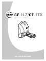
CF-1LZ/CF-1TX
Clip Fit Bracket for SMS1990 Loudspeakers
INSTALLATION GUIDE
1. SAFETY INSTRUCTIONS
The exclamation point within an
1.
2.
3.
4.
5.
6.
7.
8.
Read these instructions.
equilateral triangle is intended to
alert the user of the presence of
Keep these instructions.
important operating and maintenance
Heed all warnings.
(servicing) instructions in the literature
accompanying the apparatus.
Follow all instructions.
Do not use this apparatus near water.
Clean only with a dry cloth.
Do not block any ventilation openings. Install in accordance with the manufacturer’s instructions.
Do not install near any heat sources such as radiators, heat registers, stoves, or other apparatus
(including amplifiers) that produce heat.
9. Only use attachments/accessories specified by the manufacturer.
10. Refer all servicing to qualified service personnel. Servicing is required when the apparatus
has been damaged in any way, such as liquid has been spilled or objects have fallen into the
apparatus, the apparatus has been exposed to rain or moisture, does not operate normally, or has
been dropped.
11. The entire sound system must be designed in compliance with the current standards and laws
regarding electrical systems.
WARNING! This
equipment has been
designed to be installed
by qualified professionals
only! There are many factors
to be considered when
installing professional sound
reinforcement systems,
including mechanical and
electrical considerations, as
well as acoustic coverage and
performance. EAW Commercial
strongly recommends that this
equipment be installed only by
a professional sound installer or
contractor.
– CF-1LZ/CF-1TX
Part No. 0023391 Rev. A 11/2007
© 2007 LOUD Technologies Inc. All Rights Reserved.
Printed in China.
12. Rigging Precautions: When mounting or suspending EAW Commercial loudspeaker
enclosures, it is essential that load ratings, rigging techniques, and special safety
considerations be appropriate for the installation. Use only the mounting/rigging points
on the loudspeaker enclosure intended for this purpose. The user must determine the load
requirements, dynamic loading, and any other contributing factors affecting the loudspeaker
installation. The user must determine the proper design factor for specific applications and
the required load rating of the connection to structure. Comply with all applicable federal,
state, and local regulations.
EAW Commercial strongly recommends the following rigging system practices:
• Documentation: Thoroughly document the mounting/rigging design with detailed
drawings and parts lists.
• Analysis: Have a licensed structural engineer or other qualified professional review and
approve the mounting/rigging design before its implementation.
• Installation: Use personnel experienced and qualified for mounting/rigging loudspeakers
in accordance with and in compliance with all federal, state and local regulations.
DANGER: Loudspeakers should be mounted or suspended only by persons with knowledge
of the proper hardware and rigging techniques. Failure to follow these precautions may
result in damage to the equipment, personal injury, or death.
TABLE OF CONTENTS
1. SAFETY INSTRUCTIONS......................................................... 2
2. INTRODUCTION........................................................................ 4
3. INSTALLATION......................................................................... 5
Unpacking and Inspection..................................................... 5
Mounting Precautions............................................................ 5
CF-1TX Electrical Installation............................................... 6
CF-1LZ Electrical Installation................................................ 8
Mechanical Installation......................................................... 9
4. SERVICE INFORMATION......................................................... 11
5. EAW COMMERCIAL WARRANTY.......................................... 11
CF-1LZ/CF-1TX– 2. INTRODUCTION
This bracket allows the SMS1990 loudspeaker to be mounted to the wall, and electrically
connected in the same operation. The bracket can be wired and mounted in place, and the
loudspeaker added at a later time.
Once the bracket has been wired and mounted to the wall, the SMS1990 can be quickly
pressed onto the input connector and held securely in place. It can be easily adjusted in
vertical and horizontal angle, and locked in place with a locking wheel.
Lock/unlock wheel
Horizontal adjustment
Vertical adjustment
This manual covers two brackets:
• The CF-1TX has an internal transformer for constant voltage applications. The
transformer has multiple taps, with a selector switch to set the desired power tap
wattage for the system.
• The CF-1LZ is used for constant impedance applications, with no internal power
transformer.
The mechanical mounting details are identical for each clip-fit bracket.
– CF-1LZ/CF-1TX
3. INSTALLATION
Unpacking and Inspection
Visually inspect the outside of the shipping carton and check for any damage. After
unpacking, if you find concealed damage to the bracket, save the packing materials for
the carrier’s inspection, notify the carrier immediately, and file a shipping damage claim.
Although EAW Commercial will help in any way possible, it is always the responsibility of
the receiving party to file any shipping damage claim. The carrier will help prepare and file
this claim.
Mounting Precautions
The mounting bracket is used for wall mounting the SMS1990 loudspeaker ONLY.
WARNING: Installation should only be done by an experienced technician.
Improper installation may result in damage to the equipment, injury or death. Make
sure that the bracket is installed in a stable and secure way in order to avoid any
conditions that may be dangerous for persons or structures:
• Check to make sure that the support surface (e.g., wall, etc.) has the necessary
mechanical characteristics to support the weight of the bracket and loudspeaker
without the danger of it falling.
• Always use support elements suitable for the material of the wall that will support
the bracket (e.g., screw anchors for bricks, screw anchors for cement, etc.). Due to
various construction methods and materials used today, the hardware for securing
the bracket to the mounting surface is not supplied. Consult a building professional
for the proper mounting hardware before mounting the bracket.
• Before mounting the bracket, carefully check all the components to be used to make
sure there is no damage, deformation, corrosion and/or missing or damaged parts
that could reduce the safety of the installation.
• Consult a professional rigger or structural engineer prior to mounting brackets and
loudspeakers from a structure not intended for that use. Always know the working
load limit of the structure supporting the loudspeaker. Always make sure that the
rigging hardware minimum rating is at least five times the actual load.
• Avoid installing the bracket in places exposed to harsh weather conditions.
CF-1LZ/CF-1TX– CF-1TX Electrical Installation
Before the clip-fit bracket is mounted to the wall, the electrical connections to your
system should be made.
Note: Observe all local and national codes when installing the CF-1TX. All connections must be made with the power amplifier turned off.
The following examples of 70 V and 100 V connections show an EAW Commercial
CAM160, a typical mixer/amplifier. Its speaker-level output is a screw terminal strip, with
outputs for 25 V, 70 V, 100 V, ground, and 4 ohm.
70 V connection example
1. Connect the amplifier’s 70 V terminal to the red (+) input wire on the CF-1TX.
2. Connect the amplifier’s GND terminal to the black (–) input wire on the CF-1TX.
To CF-1TX red (+) wire
To CF-1TX black (–) wire
3. Select the power tap as shown on the next page.
100 V connection example
1. Connect the amplifier’s 100 V terminal to the red (+) input wire on the CF-1TX.
2. Connect the amplifier’s GND terminal to the black (–) input wire on the CF-1TX.
3. Select the power tap as shown on the next page.
To CF-1TX red (+) wire
To CF-1TX black (–) wire
– CF-1LZ/CF-1TX
Selecting the power tap (CF-1TX only):
Make sure the power amplifier is turned off when adjusting the power taps or making
connections.
1. Select the desired power tap by turning the switch
with a flat-ended screwdriver.
If you are using a 70 V system, the wattage ratings are: 4, 8,
16, and 32 W.
If you are using a 100 V system, the available wattage
ratings are: 8, 16, and 32 W.
Make sure that you do not overload the amplifier. This may
cause overheating to the amplifier, and possible damage to
your loudspeakers. To avoid overloading, make sure that the
selected taps on each bracket in the line add up to no more
than 80% of the rated power of the amplifier being used.
CF-1LZ/CF-1TX– CF-1LZ Electrical Installation
Note: Observe all local and national codes when installing the CF-1LZ clip-fit bracket.
All connections to the loudspeaker must be made with the power amplifier turned off.
The following example of a low-impedance connection uses a EAW Commercial CAZ800
amplifier. This amplifier uses a screw-terminal output.
PUSH
INPUT
B
B (+)
B (--)
OFF
LINE
INPUT
CONNECTION
CAZ800-AMPLIFIER
CAUTION
TO REDUCE THE RISK OF FIRE OR ELECTRIC SHOCK,
DO NOT EXPOSE THIS APPARATUS TO RAIN OR
MOISTURE. SEE INSTRUCTIONS BEFORE USING.
BREAKER
SERIAL /DATE CODE
ON
SUBSONIC
FILTER AT 30Hz
(BALANCED)
GND
AMP MODE
PUSH
A (--)
INPUT
A
MONO
STEREO
CHANNEL B BRIDGED CHANNEL A
B (+) B (-) (+)
MANUFACTURED IN CHINA
2004 LOUD TECHNOLOGIES INC.
"EAW" IS A REGISTERED TRADEMARK
OF LOUD TECHNOLOGIES INC.
(-) A (+) A (-)
BRIDGE
A (+)
OFF
ON
CLIP LIMIT
LINE
(BALANCED)
CAUTION
TO REDUCE THE RISK OF FIRE OR ELECTRIC SHOCK,
DO NOT EXPOSE THIS APPARATUS TO RAIN OR
MOISTURE. SEE INSTRUCTIONS BEFORE USING.
1. Connect the A + terminal on the amplifier to the red (+) input wire on the CF-1LZ.
CAZ800-AMPLIFIER
BREAKER
SERIAL /DATE CODE
2. Connect the A – terminal on the amplifier to the black (–) input wire on the CF-1LZ.
CHANNEL B BRIDGED CHANNEL A
B (+) B (-) (+)
(-) A (+) A (-)
MANUFACTURED IN CHINA
2004 LOUD TECHNOLOGIES INC.
"EAW" IS A REGISTERED TRADEMARK
OF LOUD TECHNOLOGIES INC.
The SMS1990 loudspeakers have a nominal impedance of 8 ohm. If you connect
other loudspeakers in parallel, make sure that the overall impedance does not drop
below the minimum required by your power amplifier.
– CF-1LZ/CF-1TX
CF-1LZ and CF-1TX Mechanical Installation
Mounting the clip-fit brackets to the wall:
a. Mount the wall bracket to the desired
surface, in this vertical orientation only.
Note that the bracket has two mounting
holes with vertical spacing that allows
them to be used with a standard wall
J-box.
The hardware for securing the wall bracket
to a mounting surface or a J-box is not
supplied. It is recommended that you
consult a rigging professional to determine
the proper hardware for mounting the
bracket.
Rotating the loudspeaker’s input section
(if required):
The SMS1990 loudspeaker can be mounted vertically (as
shown here) onto the clip-fit bracket, or horizontally. If you
want to change the orientation, follow these steps:
a.Remove the four screws holding the circular input
section in place.
b. Pull out the input section by approximately half an
inch, and rotate it through no more than 90 degrees.
c. Secure the input section into its new position with the four screws.
CF-1LZ/CF-1TX– Mounting the loudspeaker onto a bracket:
a. Once the clip-fit bracket has been wired and secured to the wall, press the
loudspeaker onto the input connector, until it clicks into place.
Make sure it is fitted on correctly. It is possible to fit it on upside-down, but it will not
click in place, or be securely held on the bracket, or make an electrical connection.
Lock
Lock/unlock wheel
Unlock
Adjusting the loudspeaker angle:
The adjustment and locking mechanism has been designed to be easy to use.
a. Rotate the locking wheel until the loudspeaker can be rotated horizontally and
vertically. Find the desired loudspeaker position, and then rotate the locking wheel
until it locks this position.
b. Perform a listening test to verify that the coverage is acceptable.
Unmounting the loudspeaker from the bracket:
a. Slide the red plastic tab towards the center of the loudspeaker, and hold while you
press the red center button inwards. Pull the SMS1990 off the bracket.
1. Slide this spring-loaded tab to
the left.
2. Press this button in.
10 – CF-1LZ/CF-1TX
4. SERVICE INFORMATION
In the event that your bracket should require servicing, please follow these instructions:
1. Call EAW Commercial Tech Support at 1-888-337-7404, 7 am to 5 p.m. PST (MondayFriday), to verify the problem and obtain a Return Authorization (RA) Number. Be sure to
have the serial number of the unit when you call. You must have a Return Authorization
Number in order to obtain warranty service at an authorized service center. You can also
e-mail EAW Commercial Tech Support at: [email protected]
2. Pack the unit in its original packaging. THIS IS VERY IMPORTANT. LOUD Technologies
is not responsible for any damage that occurs during shipping due to non-conventional
packaging. Original packaging helps to minimize the possibility of shipping damage.
3. Include a legible note stating your name, (no P.O. boxes), daytime phone number, Return
Authorization Number, and a detailed description of the problem, including how we can
duplicate it.
4. Write the Return Authorization Number in BIG BOLD PRINT on the top of the box.
5. Tech Support will tell you where to ship the unit when you call for an RA Number. We
suggest insurance for all forms of cartage.
5. EAW COMMERCIAL WARRANTY
Warranty: LOUD Technologies Inc. requires its authorized EAW Commercial distributors to
abide by the following warranty terms for all EAW Commercial brand products (all dates
are from the date of delivery from an Authorized EAW Commercial Distributor to the end
user/installation site): Loudspeakers – 5 years; Active Electronics – 5 years; Accessories
– 2 years.
What Is Covered: Defects in workmanship and materials and against malfunctions. EAW
Commercial distributors must remedy all such defects and malfunctions without charge
for parts or labor if the warranty applies. Final determination of warranty coverage lies
solely with each authorized EAW Commercial distributor.
What Is Not Covered: This warranty does not extend to damage or malfunctions
resulting from, but not limited to, shipment, improper installation, misuse, neglect,
abuse, normal wear, accident, or to any product on which the serial number has been
modified or removed. Exterior defects in or damage to the exterior appearance are
specifically excluded from this warranty. EAW Commercial distributors shall not be liable
for incidental or consequential damages resulting from the use of EAW Commercial
products. Repairs and/or modifications by other than an Authorized EAW Commercial
Distributor automatically voids this warranty.
CF-1LZ/CF-1TX– 11
EAW Commercial | One Main Street | Whitinsville, MA 01588 USA
TEL toll free within US/Canada 888.337.7404 | TEL outside US 425.892.6503 | FAX 425.485.1152
www.eawcommercial.com
©2007 LOUD Technologies Inc. All Rights Reserved. EAW Commercial is a registered trademark of LOUD Technologies Inc.