1
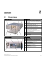
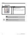
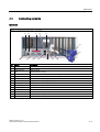
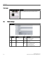
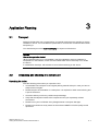
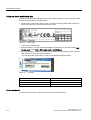
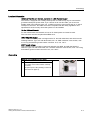
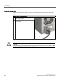
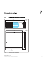
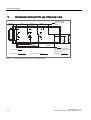
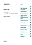
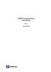
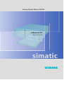
Getting Started Edition 09/2005
Industrial PC
Rack PC IL 43
simatic
DOCUMENTATION
Introduction
1
Description
2
SIMATIC
Application Planning
3
Industrial PC
Rack PC IL 43
Mounting
4
Connecting
5
Commissioning
6
Dimension drawings
7
Appendix
A
Getting Started
Edition 09/2005
A5E00432882-01
Safety Guidelines
This manual contains notices you have to observe in order to ensure your personal safety, as well as to prevent
damage to property. The notices referring to your personal safety are highlighted in the manual by a safety alert
symbol, notices referring only to property damage have no safety alert symbol. These notices shown below are
graded according to the degree of danger.
Danger
indicates that death or severe personal injury will result if proper precautions are not taken.
Warning
indicates that death or severe personal injury may result if proper precautions are not taken.
Caution
with a safety alert symbol, indicates that minor personal injury can result if proper precautions are not taken.
Caution
without a safety alert symbol, indicates that property damage can result if proper precautions are not taken.
Notice
indicates that an unintended result or situation can occur if the corresponding information is not taken into
account.
If more than one degree of danger is present, the warning notice representing the highest degree of danger will
be used. A notice warning of injury to persons with a safety alert symbol may also include a warning relating to
property damage.
Qualified Personnel
The device/system may only be set up and used in conjunction with this documentation. Commissioning and
operation of a device/system may only be performed by qualified personnel. Within the context of the safety notes
in this documentation qualified persons are defined as persons who are authorized to commission, ground and
label devices, systems and circuits in accordance with established safety practices and standards.
Prescribed Usage
Note the following:
Warning
This device may only be used for the applications described in the catalog or the technical description and only in
connection with devices or components from other manufacturers which have been approved or recommended
by Siemens. Correct, reliable operation of the product requires proper transport, storage, positioning and
assembly as well as careful operation and maintenance.
Trademarks
All names identified by ® are registered trademarks of the Siemens AG. The remaining trademarks in this
publication may be trademarks whose use by third parties for their own purposes could violate the rights of the
owner.
Disclaimer of Liability
We have reviewed the contents of this publication to ensure consistency with the hardware and software
described. Since variance cannot be precluded entirely, we cannot guarantee full consistency. However, the
information in this publication is reviewed regularly and any necessary corrections are included in subsequent
editions.
Siemens AG
Automation and Drives
Postfach 48 48
90437 NÜRNBERG
GERMANY
Order No.: A5E00432882-01
Edition 09/2005
Copyright © Siemens AG 2005.
Technical data subject to change
Table of contents
1
Introduction............................................................................................................................................. 1-1
2
Description.............................................................................................................................................. 2-1
3
4
5
6
7
A
2.1
External structure....................................................................................................................... 2-1
2.2
Operator controls ....................................................................................................................... 2-2
2.3
Connecting elements ................................................................................................................. 2-3
2.4
Status displays ........................................................................................................................... 2-4
Application Planning ............................................................................................................................... 3-1
3.1
Transport.................................................................................................................................... 3-1
3.2
Unpacking and checking the delivery unit ................................................................................. 3-1
3.3
Ambient and environmental conditions...................................................................................... 3-3
Mounting................................................................................................................................................. 4-1
4.1
Installing the device ................................................................................................................... 4-1
4.2
Technical data of the telescopic rails......................................................................................... 4-2
Connecting ............................................................................................................................................. 5-1
5.1
Connecting peripherals .............................................................................................................. 5-1
5.2
Connecting the device to power................................................................................................. 5-2
Commissioning ....................................................................................................................................... 6-1
6.1
Prerequisites for commissioning ................................................................................................ 6-1
6.2
Basic commissioning - initial power-up...................................................................................... 6-1
6.3
Reinstalling the software............................................................................................................ 6-2
Dimension drawings ............................................................................................................................... 7-1
7.1
Dimensional drawing of the device ............................................................................................ 7-1
7.2
Dimensional drawing for the use of telescopic rails................................................................... 7-2
Appendix.................................................................................................................................................A-1
A.1
Guidelines and declarations....................................................................................................... A-1
A.2
Certificates and approvals ......................................................................................................... A-2
A.3
Service and support ................................................................................................................... A-3
SIMATIC Rack PC IL 43
Getting Started, Edition 09/2005, A5E00432882-01
iii
Table of contents
iv
SIMATIC Rack PC IL 43
Getting Started, Edition 09/2005, A5E00432882-01
Introduction
1
Purpose of this document
This Getting Started documentation contains all the information you need for commissioning
and using the SIMATIC Rack PC IL 43.
Scope of validity of this document
This documentation is valid for all supplied variations of the SIMATIC Rack PC IL 43 and
describes the state of delivery as of September 2005.
Operating instructions SIMATIC Rack PC IL 43
Additional information is available on the supplied CD "Rack PC IL 43 Documentation and
Drivers". To view and print the operating instructions, run Start and follow the instructions on
the screen.
The operating instructions provide many useful topics dealing with items such as hardware
expansion options, changing the device configuration and technical data.
Conventions
The abbreviation Rack PC or device is also used within this documentation for the product
name SIMATIC Rack IL PC 43.
Note
Safety-related information
To avoid damage to assets and for the sake of your own personal safety, please take note of
the information on safety in this Getting Started and in the operating instructions. A warning
triangle references this safety-related information and, depending on the potential hazard, is
shown as follows:
SIMATIC Rack PC IL 43
Getting Started, Edition 09/2005, A5E00432882-01
1-1
Introduction
1-2
SIMATIC Rack PC IL 43
Getting Started, Edition 09/2005, A5E00432882-01
2
Description
2.1
External structure
Front view of the device
Rear view of the device
SIMATIC Rack PC IL 43
Getting Started, Edition 09/2005, A5E00432882-01
Description
(1)
Front panel with aperture for ventilation of the
device (filter mat and fan are located behind this
front panel)
(2)
Option for installing DVD-ROM,
DVD-ROM/CD-RW drives, DVD burner and
removable racks for hard disks
(3)
Option for installing DVD-ROM,
DVD-ROM/CD-RW drive, DVD burner
(4)
On/off button
(5)
Front door with lock,
provides protection against dirt and
unauthorized access. Keep the door closed
during normal operation.
(6)
Floppy disk
(7)
USB ports
(8)
Status displays
Pos
Pos
Description
(1)
Power unit fan
(2)
Option for installing a cover for external ports
(3)
Expansion slots
4 x PCI, 2x PCIe x1, 1x PCIe x16
(4)
Connecting elements
(5)
Rating plate (may also be mounted on the
inside of the front panel door)
(6)
Fan aperture
Installation option for 60 mm fan
(7)
Power supply connection
2-1
Description
2.2 Operator controls
2.2
Operator controls
Operator control on/off button
Pos
Description
(1)
The on/off/reset buttons have three functions:
- Switch on the PC (press briefly 1x)
- Shut down the operating system and PC
(press briefly 1x)
- Switch off the PC without shutting down the operating system
(press and hold more than 4 seconds) = hardware reset
Caution
Data may be lost when the PC performs a hardware reset.
Warning
The on/off button signal does not switch off power to the PC!
2-2
SIMATIC Rack PC IL 43
Getting Started, Edition 09/2005, A5E00432882-01
Description
2.3 Connecting elements
2.3
Connecting elements
Interfaces
Layout of the interfaces on the rear of the device
Pos
Name
Description
(1)
MOUSE
Connection for a PS/2 mouse
(2)
USB C and D
USB connector
(3)
LPT
Parallel interface, 25-pin
(4)
LAN
RJ 45 Ethernet connection 10/100/1000 Mbps
(5)
COM 2
Serial port 1 (V.24), 9-pin Cannon connector (optional)
(6)
VGA 1
Dual Head VGA adapter (optional)
(7)
VGA 2
Dual Head VGA adapter (optional)
(8)
Micro (input)
Microphone connection
(9)
Audio (output)
Headphone connection
(10)
Audio (input)
Connection for linear audio source
(11)
USB A and B
USB connector
(12)
VGA
Connection for VGA monitor
(13)
COM 1
Serial port 1 (V.24), 9-pin Cannon connector
(14)
KEYBOARD
Connection for a PS/2 keyboard
SIMATIC Rack PC IL 43
Getting Started, Edition 09/2005, A5E00432882-01
2-3
Description
2.4 Status displays
Power supply
Position of the IEC power plug
Description
IEC power connector for the AC power supply to the device. The
maximum permitted power range is 120 V AC to 240 V AC
2.4
Status displays
Status displays
(1)
Display
Meaning
LED
Description
POWER
PC status display
OFF
•
•
•
Hibernate, switched off or power off
Windows standby
PC in operation
•
•
no access
Access
•
•
•
•
CPU temperature critical
CPU heatsink fan fault
Enclosure fan fault
Power supply fan fault
YELLOW
GREEN
(2)
(3)
HARDDISK
STATUS
Display for hard disk
access
OFF
Fan status
FLASH
GREEN
RED
2-4
SIMATIC Rack PC IL 43
Getting Started, Edition 09/2005, A5E00432882-01
Application Planning
3.1
3
Transport
Although the Rack PC has a rugged design, its internal components are sensitive to severe
vibrations or shock. You must therefore protect the PC from severe mechanical stress when
transporting it.
You should always use the original packaging for shipment of the device.
Caution
Risk of damage to the device!
When transporting the PC in cold weather it may be submitted to extreme variations in
temperature. In this situation, make sure that condensation does not develop on or inside
the device.
If condensation develops, wait at least 12 hours before switching on the device.
3.2
Unpacking and checking the delivery unit
Unpacking the device
Note the following points when you unpack the unit
• It is advisable not to dispose of the original packing material. Keep it in case you have to
transport the unit again.
• Please keep the documentation in a safe place. It is required for initial commissioning and
is part of the device.
• Check the delivery unit for any visible transport damage.
• Verify that the shipment contains the complete unit and your separately ordered
accessories.
• Please inform your local dealer of any disagreements or transport damages.
• Please inform Siemens AG by means of the enclosed SIMATIC IPC/PG quality control
report form.
SIMATIC Rack PC IL 43
Getting Started, Edition 09/2005, A5E00432882-01
3-1
Application Planning
3.2 Unpacking and checking the delivery unit
Noting the device identification data
The device can identified uniquely with the help of these numbers in case of repairs or theft.
Enter the following data in the table below:
• Serial number: The serial number (S VP) is located on the type plate either on the rear
panel of the device or on the inside of the front door.
Figure 3-1
Rating plate
• Order number of the device
• Ethernet address: You find the Ethernet address of the device in your BIOS Setup (F2
function key) , under Info > (F1 function key) > LAN Address.
• Microsoft Windows "Product Key" from the "Certificate of Authenticity" (COA). The COA
label is found on the inside of the front door.
You may need the Product Key in case you reinstall the operating system.
Figure 3-2
COA label
Serial number
S VP ...
Order No.
6AG ...
Microsoft Windows Product Key
Ethernet address
Device equipment
You will find a list of device equipment on a sign behind the front door.
3-2
SIMATIC Rack PC IL 43
Getting Started, Edition 09/2005, A5E00432882-01
Application Planning
3.3 Ambient and environmental conditions
3.3
Ambient and environmental conditions
When you plan your project, you should make allowances for:
• Note the climatic and mechanical environmental conditions specified in the technical data
in your operating manual.
• Avoid extreme ambient conditions as much as possible. Protect your PC from dust,
moisture, and heat.
• The device has been designed for usage in a normal industrial environment according to
IEC 60721-3-3 (pollutant class 3C2 for chemical influence, 3S2 for sand and dust.)
SIMATIC Rack PCs may not be used in severe operating environments, for example
locations with acidic vapors or gasses, without additional protective measures (such as
the provision of clean air.)
• Keep the PC out of direct sunlight.
• Mount the PC as safely as possible to prevent danger (for example, of falling over).
• The device satisfies protection class IP 30 on the front panel.
• The clearance in the area of the ventilation slots must be at least 50 mm, so that the PC
is sufficiently ventilated.
• Do not cover the vent slots of the device.
• The device enclosure satisfies fire protection requirements to EN 60950. It may therefore
be installed without additional fire-proofing measures.
Warning
If these conditions are not upheld while mounting the system, the approvals according to
UL 60950, EN 60950 are forfeited and there is a danger of overheating and personal
injury.
SIMATIC Rack PC IL 43
Getting Started, Edition 09/2005, A5E00432882-01
3-3
Application Planning
3.3 Ambient and environmental conditions
3-4
SIMATIC Rack PC IL 43
Getting Started, Edition 09/2005, A5E00432882-01
4
Mounting
4.1
Installing the device
Possible areas of installation
The device may be installed in control desks, switching cabinets and 19`` rack systems, both
horizontally and vertically.
Possible mounting methods
Options of mounting the device
• Mounting on angle brackets
• Installation on device bases
• Tower installation: a separate tower kit can be ordered for tower installation.
• Installing with telescopic rails
When telescopic rails are used, the devices can be completely removed from the cabinet
or rack.
Refer to the sections "Technical data of the telescopic rails" and "Dimensional drawing for
the use of telescopic rails" for more detailed information.
Position of the mounting holes (1) for angle brackets or telescopic rails
Caution
The mounting screws of the telescopic rails may not protrude into the enclosure by more
than 5 mm.
SIMATIC Rack PC IL 43
Getting Started, Edition 09/2005, A5E00432882-01
4-1
Mounting
4.2 Technical data of the telescopic rails
Note
For vertical operation, install the device on a horizontal metal base and secure it against
tipping. The following decide bases are available from Rittal for this purpose:
Rittal Type TE 7000.620, Rittal Type VR 3861.580, Rittal Type DK 7063.710.
Please refer to the case manufacturer's instructions regarding device bases.
Caution
Danger of bodily harm!
It is not permitted to install the device only on the 19" brackets of the front panel.
4.2
Technical data of the telescopic rails
Ultimate load per pair
Minimum 30 kg
Full extraction length
Minimum 470 mm
Rail thickness
Maximum 9.7 mm
Fixing Screws
M5 x 6 mm
The mounting screws of the telescopic rails may not protrude by more than 5 mm into the
enclosure.
4-2
SIMATIC Rack PC IL 43
Getting Started, Edition 09/2005, A5E00432882-01
Connecting
5.1
5
Connecting peripherals
Note before connecting
Notice
Connect only I/O modules approved for industrial applications to EN 61000-6-2:2001.
Note
Hot-plug I/O modules (USB) may be connected while the PC is in operation.
Caution
I/O devices not capable of hot-plugging may only be connected after the device has been
disconnected from the power supply.
Caution
Strictly adhere to the specifications for I/O modules.
SIMATIC Rack PC IL 43
Getting Started, Edition 09/2005, A5E00432882-01
5-1
Connecting
5.2 Connecting the device to power
5.2
Connecting the device to power
To be noted before you connect the device
Note
The long-range power supply module is designed for operation on 100-240 networks. It is
not necessary to adjust the voltage range.
Warning
Do not connect or disconnect power and data cables during thunderstorms.
Warning
The device is designed for operation on grounded power supply networks (TN systems to
VDE 0100, part 300, or IEC 60364-3).
Operation on ungrounded or impedance-grounded power networks (IT networks) is
prohibited.
Warning
The permitted rated voltage of the device must conform with local mains voltage.
Caution
The mains connector must be disconnected to fully isolate the device from mains. Ensure
easy access to this area.
A master mains disconnect switch must be installed if the device is mounted in a switch
cabinet. Always ensure free and easy access to the power inlet on the device, or that the
safety power outlet of the building installation is freely accessible and located close to the
device.
5-2
SIMATIC Rack PC IL 43
Getting Started, Edition 09/2005, A5E00432882-01
Connecting
5.2 Connecting the device to power
Localized information
Outside of the USA and Canada, operation on a 230 V power supply:
This device is equipped with a safety-tested power cord which may only be connected to
grounded shockproof power outlet. If you choose not to use this cable, you must use a
flexible cable of the following type: min. 18 AWG conductor cross-section and 15-A / 250-V
shockproof connector. The cable set must be compliant with the safety regulations and
stipulated IDs of the country where the system is to be installed.
For the USA and Canada:
For the United States and Canada, a CSA or UL-listed power cord must be used.
The connector must be compliant with NEMA 5-15.
120 V AC power supply
To be used is a flexible power cord approved to UL and with CSA label, and which has the
following features: Type SJT with three leads, min. 18 AWG conductor cross-section, max.
4.5 m long and tandem ground contact connector 15 A, min. 125 V.
240 V supply voltage
Use a flexible power cord with UL approval and with CSA label, and with the following
features: Type SJT with three leads, min. 18 AWG conductor cross-section, max. 4.5 m long
and tandem ground contact connector 15 A, min. 250 V.
Connecting
Steps for connecting the device to mains
1
Connect the IEC connector.
2
Connect the power cord to the mains outlet,
then switch on the mains isolation switch (if
this exists).
The yellow power LED (standby) on the front
panel of the PC lights up.
SIMATIC Rack PC IL 43
Getting Started, Edition 09/2005, A5E00432882-01
5-3
Connecting
5.2 Connecting the device to power
Secure the power plug
You can secure the power plug in order to avoid unintentional disconnection of the power
cord.
Steps in securing the power plug
1
Remove the fastening screw (1) on the
power supply module.
2
Power plug clamp (2) screw it to the power
supply module
Warning
If the power plug is secured with a clamp, the power outlet must be freely accessible to allow
the device to be easily removed from the mains.
5-4
SIMATIC Rack PC IL 43
Getting Started, Edition 09/2005, A5E00432882-01
Commissioning
6.1
6
Prerequisites for commissioning
• Before you switch on the device, you should verify that the peripherals are connected, i.e.
the keyboard, mouse, monitor and the power supply.
• The operating system of your device is preinstalled on the hard disk.
Caution
Risk of damage to the device!
Make sufficient allowances for the device to acquire room temperature before you put it
into use. If condensation develops, wait at least 12 hours before switching on the device.
6.2
Basic commissioning - initial power-up
The Rack PC operating system is automatically set up the first time you switch on the
device. Procedure:
1. Press the on/off button. The green power LED lights up. The PC performs a POST. During
this self-test, this message appears:
Press <F2> to enter SETUP
2. Wait until this message is cleared, then follow the instructions on the screen.
3. Type in the Product Key as required. You can find this key on the "Certificate of
Authentication", in the "Product Key" line.
Notice
The PC may not be switched off when you run setup.
Do not change the default BIOS settings as this will disrupt the operating system installation.
4. Automatic restart
After you have entered all necessary information and after the operating system
setup is completed, the PC is automatically restarted and displays the user interface of the
relevant operating system.
SIMATIC Rack PC IL 43
Getting Started, Edition 09/2005, A5E00432882-01
6-1
Commissioning
6.3 Reinstalling the software
From now on, after you switch on the PC, the user interface of the operating system is
automatically opened when the startup routine is completed.
Switch off the device
Note
On a Windows platform, always shut down the PC by clicking Start > Close.
Press the on/off button behind the front panel door. The green power LED is switched off.
Disconnect the mains connector to isolate the device from mains.
6.3
Reinstalling the software
General installation procedure
In case of errors in your software installation, you can reinstall your software using the
Recovery CD, the Documentation and Drivers CD or the Restore DVD.
• Recovery CD: The new recovery procedure is based on Windows PE (Preinstall
Environment). The CD contains the Windows PE user interface with tools for configuring
the hard drives and the operating system.
• Documentation and Drivers CD: Contains the documentation and the hardware drivers.
• Restore DVD: Contains a hard disk image file with the original software (operating system
with installed hardware drivers).
Restoring the factory condition
• Place the Restore DVD into the drive and restart the device using the on/off switch.
• During the BIOS self-test, press the F12 key. After initialization, a "Boot Menu" is
displayed.
• Select the optical drive with the cursor keys.
• Now follow the instructions on the screen.
Caution
All existing data, programs, user settings, authorizations and license keys on the drives
will be deleted and are therefore lost.
For information on the functions, refer to the README.TXT file on the Restore DVD.
6-2
SIMATIC Rack PC IL 43
Getting Started, Edition 09/2005, A5E00432882-01
7
Dimension drawings
7.1
Dimensional drawing of the device
oben bei
senkrechtem
Einbau
465.1
18.31
176.5
6.94
101.6
4
483
19.01
oben bei
senkrechtem
Einbau
Dimensions:
Figure 7-1
19.39
17.68
492.54
449.04
433.5
17.06
mm
Inch
Dimensional drawing of the device
SIMATIC Rack PC IL 43
Getting Started, Edition 09/2005, A5E00432882-01
7-1
Dimension drawings
7.2 Dimensional drawing for the use of telescopic rails
Dimensional drawing for the use of telescopic rails
100±T1
3.937±T1
100±T1
3.937±T1
Dimensions for telescopic
rails by the company Rittal
type 3659
100±T1
3.937±T1
72.6 ± T2
2.858 ± T2
33.54±T3
1.32±T3
127±T1
5±T1
Dimensions:
T1=Tolerance ±
Figure 7-2
7-2
209.6±T1
8.251±T1
355.6±T1
14±T1
mm
Inch
0,1 mm
0.004 Inch
T2=Tolerance ±
0,3 mm
0.01 Inch
88.5 ± T2
3.484 ± T2
7.2
Dimensions for telescopic
rails by the company Schroff
type 69000-122
T3=Tolerance ± 0,5 mm
0.02 Inch
Dimensional drawing for the use of telescopic rails
SIMATIC Rack PC IL 43
Getting Started, Edition 09/2005, A5E00432882-01
A
Appendix
A.1
Guidelines and declarations
Notes on the CE Label
The following applies to the SIMATIC product described in this documentation:
EMC Guidelines
This product fulfills the requirements for the EC directive ™89/336/EEC Electromagnetic
Compatibility", and the following fields of application apply according to this CE label:
Area of application
Requirements for
Emitted interference
Noise Immunity
Industry
EN 61000-6-4: 2001
EN 61000-6-2: 2001
Residential and commercial areas and
small businesses
EN 61000-6-3: 2001
EN 61000-6-1: 2001
The device complies with the standards EN 61000-3-2:2000 (harmonic currents) and
EN 61000-3-3:1995 (voltage fluctuation and flicker.)
Low-voltage directive
The devices complies with the requirements of the EC Directive 73/23/EEC "Low Voltage
Directive." Conformance with this standard has been verified according to EN 60950.
Declaration of conformity
The EC declaration of conformity and the corresponding documentation are made available
to authorities in accordance with the EC directives stated above. Your sales representative
can provide these on request.
Observing the Installation Guidelines
The installation guidelines and safety instructions given in this documentation must be
observed during commissioning and operation.
Connecting peripherals
The requirements regarding noise immunity to EN 61000-6-2:2001 are met when you
connect a peripheral suitable for an industrial environment. Peripheral devices are only be
connected via shielded cables.
SIMATIC Rack PC IL 43
Getting Started, Edition 09/2005, A5E00432882-01
A-1
Appendix
A.2 Certificates and approvals
A.2
Certificates and approvals
DIN ISO 9001 certificate
The quality assurance system for the entire product process (development, production, and
marketing) at Siemens fulfills the requirements of ISO 9001 (corresponds to EN29001:
1987).
This has been certified by DQS (the German society for the certification of quality
management systems.)
EQ-Net certificate no.: 1323-01
Software License Agreement
The device is shipped with preinstalled software. Please observe the corresponding license
agreements.
Certification for the USA, Canada and Australia
Safety
One of the following markings on a device is indicative of the corresponding approval:
Underwriters Laboratories (UL) to UL 60950 Standard (I.T.E), or to UL508
(IND.CONT.EQ)
Underwriters Laboratories (UL) according to Canadian standard C22.2 No. 60950
(I.T.E) or C22.2 No. 142 (IND.CONT.EQ)
Underwriters Laboratories (UL) according to standard UL 60950, Report E11 5352 and
Canadian standard C22.2 No. 60950 (I.T.E) or UL508 and C22.2 No. 142
(IND.CONT.EQ)
UL recognition mark
Canadian Standard Association (CSA) according to the standard C22.2. No. 60950 (LR
81690) or C22.2 No. 142 (LR 63533)
Canadian Standard Association (CSA) to the American Standard UL 60950 (LR 81690),
or to the UL 508 (LR 63533)
A-2
SIMATIC Rack PC IL 43
Getting Started, Edition 09/2005, A5E00432882-01
Appendix
A.3 Service and support
EMC
USA
Federal Communications
Commission
Radio Frequency
Interference Statement
This equipment has been tested and found to comply with the limits for a
Class A digital device, pursuant to Part 15 of the FCC Rules. These limits
are designed to provide reasonable protection against harmful
interference when the equipment is operated in a commercial
environment. This equipment generates, uses, and can radiate radio
frequency energy and, if not installed and used in accordance with the
instruction manual, may cause harmful interference to radio
communications. Operation of this equipment in a residential area is likely
to cause harmful interference in which case the user will be required to
correct the interference at his own expense.
Shielded Cables
Shielded cables must be used with this equipment to maintain compliance
with FCC regulations.
Modifications
Changes or modifications not expressly approved by the manufacturer
could void the user's authority to operate the equipment.
Conditions of Operations
This device complies with Part 15 of the FCC Rules. Operation is subject
to the following two conditions: (1) this device may not cause harmful
interference, and (2) this device must accept any interference received,
including interference that may cause undesired operation.
CANADA
Canadian Notice
This Class A digital apparatus complies with Canadian ICES-003.
Avis Canadian
Cet appareil numérique de la classe B est conforme à la norme NMB-003
du Canada.
AUSTRALIA
This product meets the requirements of the AS/NZS CISPR 22 Standard.
A.3
Service and support
Further support
If you have any further questions relating to the products described in this documentation,
contact your local representative at the SIEMENS office nearest you.
You can locate your contact partner on this Internet URL:
http://www.siemens.com/automation/partner
A guide to our technical documentation for the various SIMATIC products and systems is
available at:
http://www.siemens.de/simatic-tech-doku-portal
The online catalog and the online ordering system is available at:
http://mall.automation.siemens.com/
SIMATIC Rack PC IL 43
Getting Started, Edition 09/2005, A5E00432882-01
A-3
Appendix
A.3 Service and support
Training center
Siemens offers a number of training courses to familiarize you with the SIMATIC automation
system. Please contact your regional Training Center, or the central Training Center in
D90327 Nuremberg.
Telephone: +49 (911) 895-3200.
Internet: http://www.sitrain.com
Technical Support
You can reach Technical Support for all A&D products using the Web form for Support
Request available under
http://www.siemens.de/automation/support-request
Further information about our technical support is available in the Internet at
www.siemens.com/automation/service
When you contact the Customer Support, please have the following information for the
technician on hand:
• BIOS version
• Order No. (MLFB) of the device
• Installed additional software
• Installed additional hardware
Service & Support on the Internet
In addition to our documentation services, you can also make use of all our online
knowledge base on the Internet.
http://www.siemens.com/asis
There you find:
• The Newsletter contains the latest information on your products.
• Numerous documents are available by searching through Service & Support.
• The current BIOS version.
• A forum is available for users and specialists to exchange experiences.
• You can find your local contact for Automation & Drives in our contacts database.
• Information about on-site services, repairs, spare parts. Lots more is available on the
”Services” page.
You can find the latest information about industrial PCs at the following address
http://support.automation.siemens.com
A-4
SIMATIC Rack PC IL 43
Getting Started, Edition 09/2005, A5E00432882-01
Siemens AG
Automation and Drives
Industrial Automation Systems
Postfach 4848
90437 NUERNBERG
Federal Republic of Germany
www.siemens.de/automation
,'$(