1
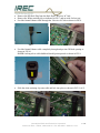
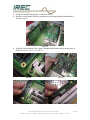
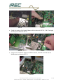
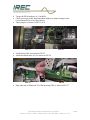
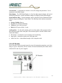
C R O W N / O M N I A
D P 3
D
I
G
I
T
A
L
A
U
D
I
C
A
O
R
P
R
O
C
E
S
S
I
N
G
D
I N S T A L L A T I O N
&
O P E R A T I O N
M A N U A L
CROWN BROADCAST/IREC 25166 Leer Drive Elkhart, IN 46514
TEL: +1 (574) 262-8900 FAX: +1 (574) 262-5399
E-MAIL: [email protected]
www.crownbroadcast.com
revision 1.00
International Radio and Electronics Corporation
25166 Leer Drive Elkhart, Indiana 46514 • 574–262–8900 • www.irec1.com
i
GREETINGS!
Welcome to the Crown DP3 Audio Processor, the first digital audio processor
designed exclusively for the Crown Broadcast transmitter line.
The DP3 applies the same advanced design philosophy as the entire Omnia
family, to yield performance and flexibility never before available as an internal
transmitter option.
The DP3, like all Omnia products, delivers crystal-clear highs, thundering bass
and amazing loudness, with none of that “digital grunge aftertaste!”
The DP3 is a fully digital system that is available as an upgrade to current Crown
transmitters, and as a new product option for either our industry standard FM
transmitter line, or our FMX digitally controlled transmitters.
DP3’s flexibility is built- into the design. Instead of keeping the processing
algorithms on a set of EPROM’s or proprietary potted modules, the system’s DSP
(Digital Signal Processing) resources are entirely configured through software
contained in the DP3 card.
Even fundamental rearrangements of the system architecture can be easily
accomplished in the field by using the web-browser based remote control
application, via ETHERNET connection.
International Radio and Electronics Corporation
25166 Leer Drive Elkhart, Indiana 46514 • 574–262–8900 • www.irec1.com
ii
T A B L E
O F
C O N T E N T S
Introduction and Contents…………………………………………..
Table of Contents…………………………………………………
Specifications…………………………………………………….
Warranty………………………………………………………….
i- vii
iii
vi
vii
SECTION 1: Field Installation Instructions
1.2. FMA Transmitter……………………………………………. 1-2
1.3. FMX Transmitter……………………………………………. 1-8
SECTION 2: OMNIA DP-3 Operation – Crown FMA Transmitter.. 2-1
SECTION 3: OMNIA DP-3 Operation – FMX-DMS Transmitter
3.1. Initial Power-up Procedures………………………………….. 3-1
3.2. Controls and Display…………………………………………. 3-2
3.3. Operating the FMX…………………………………………… 3-4
3.4. Passwords…………………………………………………….. 3-4
3.5. Readings Function List………………………………………. 3-4
3.6. Settings Function List………………………………………… 3-6
3.7. Factory Settings………………………………………………. 3-7
3.8. Audio Monitor………………………………………………… 3-7
3.9. Fault Log……………………………………………………… 3-8
3.10. Power-up Procedure…………………………………………. 3-8
3.11. DP3 Processor Function List………………………………… 3-9
SECTION 4: DP-3 REMOTE Control Interface via Computer
ETHERNET Port
4.1. Preparatory Needs for ETHERNET connection……………… 4-1
4.2. Instruc tions for ETHERNET connection…………………….. 4-2
SECTION 5: APPENDICES
5.1. Network card configuration………………………………….. 5-1
5.2. Troubleshooting……………………………………………… 5-18
5.3. Guide for adjusting processing parameters of DP3………….. 5-20
International Radio and Electronics Corporation
25166 Leer Drive Elkhart, Indiana 46514 • 574–262–8900 • www.irec1.com
iii
WARNING -- This equipment generates, uses, and can radiate radio frequency
energy. If not installed and used in accordance with the instructions in this manual
it may cause interference to radio communications. It has been tested and found to
comply with the limits for a Class A computing device (pursuant to subpart J of
Part 15 FCC Rules), designed to provide reasonable protection against such
interference when operated in a commercial environment. Operation of this
equipment in a residential area is likely to cause interference, at which case, the
user, at his own expense, will be required to take whatever measures may be
required to correct the interference.
CANADA WARNING – This digital apparatus does not exceed the Class A
limits for radio noise emissions set out in the Radio Interference Regulations of
the Canadian Department of Communications. Le present appareil numerique
n'emet pas de bruits radioelectriques depassant les limits applicables aux
brouillage radioelectrique edicte par le ministere des Communications de Canada.
NOTICES
All versions, claims of compatibility, trademarks, etc. of hardware and software
products not made by Crown Broadcast, but mentioned in this manual or other
accompanying material, are informational only. Crown Broadcast makes no
endorsement of any particular product for any purpose, nor claims any
responsibility for its operation or the accuracy of the presentation.
Trademarks
Crown Broadcast, and the Crown Broadcast mark are trademarks of International
Radio and Electronics, Inc. (IREC). All other trademarks mentioned in this
manual are the property of their respective holders.
Copyright
Copyright © 2005-IREC. All rights reserved. Published by IREC, who reserves
the right to make improvements or changes to the products described herein
(which may affect the product specifications) and to revise this manual as
required without notice.
Repair Procedures
You must contact Crown Broadcast for a Return Authorization number before
returning any products. Packages without proper authorization may be refused.
Write the RA number on the shipping label side of the returned package. Be sure
to adequately insure your shipment. Customers in North America can contact
Crown Broadcast customer support at +1 (866) 262-8917. All other customers
should contact their local dealer to verify the problem and then contact Crown
Broadcast Customer Service to arrange for repair.
International Radio and Electronics Corporation
25166 Leer Drive Elkhart, Indiana 46514 • 574–262–8900 • www.irec1.com
iv
Caution
The installation and servicing instructions presented in this manual are for use by
qualified installation and service personnel only. To avoid electric shock, do not
perform any servicing other than that contained in the operating instructions
unless you are qualified to do so. Refer all servicing to qualified personnel.
Warning
To reduce the risk of electrical shock, do not expose this product to rain or
moisture.
International Radio and Electronics Corporation
25166 Leer Drive Elkhart, Indiana 46514 • 574–262–8900 • www.irec1.com
v
SPECIFICATIONS
All measurements referenced to 100% output. It is not possible to quantify the
specifications of the gain controlling functions of the AGC and limiter sections
due to the dynamic nature of the DP3 system under program conditions. To
properly evaluate these functions, there is only one known precise set of test gear
for that—your ears! Listen and judge carefully.
Audio performance *
•
•
•
•
Frequency Response: ±0.2 dB, 50 Hz - 15 kHz
System Distortion: 0.017% THD, flat or de-emphasized
Signal-to-Noise Ratio: >80 dB, flat or de-emphasized
Channel Separation: >85 dB, 10 Hz - 15 kHz
Analog I/O Section
•
•
•
•
•
Left & Right Audio Inputs: 10 k ohms (or 600 ohms, configurable via on board jumpers) electronically balanced bridging
input, 20-bit analog-to-digital converter
Maximum Input Level: +24 dBu
Connector: XLR, female, EMI suppressed
Discrete Left/Right Audio Outputs: 600 Ω load or greater, un-balanced, 18-bit digital-to-analog
converter, de-emphasized (50 or 75 µs via ETHERNET port configuration)
Connector: Phono Jack
Digital I/O Section
•
•
•
Configuration: Stereo AES/EBU ; automatic detection on Analog/Left input XLR.
Input Sampling Rates: 32 kHz, 44.1 kHz, 48 kHz, sample rate converter provided
Input Connector: XLR, female, balanced and floating
Composite I/O Section
•
•
•
•
SCA / RBDS Subcarrier Input: BNC, unbalanced
Impedance: 50 ohms
Signal: 53 kHz subcarrier is summed into composite output.
Software controls: Input level attenuation control in ETHERNET port configuration
Pilot Output
•
Software control: Output level
Composite Output
•
Composite Output Level: 0 – 6 Volts p-p, software adjustable (feeds exciter board).
Computer Interface
•
•
•
Configuration: Ethernet 10/100.
Communications: web browser
Software-controlled (through the remote application).
Dimensions & Weight
•
5.5” x 10.75” plug-in card (14 x 27 cm)
In the interests of product improvement, Crown Broadcast reserves the right to change, add or modify any
specification.
* Test performance measured at the Audio Monitor Jacks on the rear panel
International Radio and Electronics Corporation
25166 Leer Drive Elkhart, Indiana 46514 • 574–262–8900 • www.irec1.com
vi
Warranty
Crown Broadcast, IREC warrants its broadcast products to the ORIGINAL
PURCHASER of a NEW Crown Broadcast product, for a period of three
(3) years after shipment from Crown Broadcast. All products are
warranted to be free of defects in materials and workmanship and meet or
exceed all specifications published by Crown Broadcast. Product
nameplate with serial number must be intact and not altered in any way.
This warranty is non - transferable. This warranty in its entirety is the only
warranty offered by Crown Broadcast. No other warranties, expressed or
implied, will be enforceable.
Exclusions
Crown Broadcast will not warranty the product due to misuse, accident,
neglect and improper installation or operation. Proper installation includes
A/C line surge suppression, lightning protection and proper grounding of
the entire transmitter, and any other recommendations designated in the
instruction manual. This warranty does not extend to any other products
other than those designed and manufactured by Crown Broadcast. This
warranty does not cover any damage to any accessory such as loads,
transmission line or antennas resulting from the use or failure of a Crown
Broadcast transmitter. Warranty does not cover any loss of revenue
resulting from any failure of a Crown Broadcast product, act of God, or
national disaster.
Procedure for Obtaining Warranty Service
Crown Broadcast will repair or replace, at their discretion, any product
failure as a result of normal intended use. Warranty repair can only be
performed at our plant facility in Elkhart, Indiana USA or at a factory
authorized service depot. Expenses in remedying the defect will be borne
by Crown Broadcast, including two – way ground transportation cost within
the continental United States.
Prior to returning any product or component to Crown Broadcast for
warranty work or repair a Return Authorization (RA) number must be
obtained from the Crown Broadcast Customer Service Department.
Product must be returned in the original factory pack or equivalent.
Original factory pack materials may be obtained at a nominal charge by
contacting Crown Broadcast Customer Service. Resolution of the
defective product will be made within a reasonable time from the date of
receipt of the defective product.
International Radio and Electronics Corporation
25166 Leer Drive Elkhart, Indiana 46514 • 574–262–8900 • www.irec1.com
vii
Warranty Alterations
No person has the authority to enlarge, amend or modify this warranty, in
whole or in part. This warranty is not extended by the length of time for
which the owner was deprived the use of the product. Repairs and
replacement parts that are provided under the terms of this warranty shall
carry only the unexpired portion of the warranty.
Product Design Changes
Crown Broadcast reserves the right to change the design and
manufacture of any product at any time without notice and without any
obligation to make corresponding changes in products previously
manufactured.
Legal Remedies of Purchaser
This written warranty is given in lieu of any oral or implied warranties not
contained herein. Crown disclaims all implied warranties including any
warranties of merchantability or fitness for a particular purpose.
Crown Broadcast
25166 Leer Drive
Elkhart, Indiana 46514 - 5425
Phone 574 – 262 - 8900
Fax 574 – 262 – 5399
www.crownbroadcast.com
International Radio and Electronics Corporation
25166 Leer Drive Elkhart, Indiana 46514 • 574–262–8900 • www.irec1.com
viii
1 SECTION 1: DP-3 FIELD INSTALLATION
The Crown-Omnia DP3 Processor Card can be ordered as part of a new Crown
Broadcast transmitter, or it can be ordered as an upgrade for installation in a currently
owned Crown transmitter. In the first case we worry about installing the card. In the
second case you do.
Still, do not worry much. The DP-3 has been designed for straightforward, even easy,
installation into all Crown transmitters. “Easy installation” can be slippery terminology
when applied to complex technical items, but we think we can back it up here.
If you are upgrading a transmitter you already own, first of all let us congratulate you on
your decision to add the state-of-the-art audio processing of the Crown-Omnia DP-3 to
your broadcasts. Although we have been pleased over the years with the response we
have gotten from users of our basic processor design, we are very excited about the
addition of Omnia processing power to Crown transmitters.
The DP-3 adds many new possibilities to the sound of your radio. From Omnia presets
to your own personally tweaked signature audio, your broadcasts will never sound better.
PC control of the processing elements, along with programmable addresses for your
personal presets, give flexible new processing tools to every kind of user.
And even though we believe the DP-3 installation will be crystal clear and classic in its
simplicity, please take a few minutes to read through this chapter before proceeding with
the installation.
1.1
UNPACKING – VERIFYING PARTS
By now, you’ve gotten the DP-3 processor card out of its shipping pack. Check for
damage to report to your dealer. Be sure to inspect the DP-3 and shipping carton for any
shipping damage, which must be reported to your carrier for any claims.
The DP-3 shipping box includes the following items:
• DP-3 processor card
• DP-3 Operating Manual- which you are reading now.
• Warranty Registration Card (fill it out and return it)
• ETHERNET Cable
International Radio and Electronics Corporation
25166 Leer Drive Elkhart, Indiana 46514 • 574–262–8900 • www.irec1.com
1-1
1.2 CROWN-OMNIA DP3 INSTALLATION INSTRUCTIONS – FMA
TRANSMITTER
1
2
FIG 1
•
•
•
•
•
Remove Top Cover and keep hardware to be used when finished with installation.
Remove the eight screws holding item 1 and item 2 in the unit as shown in FIG 1.
Keep all hardware, as it will be used in the DP3 PWA installation.
Remove Stereo Generator PWA (1) as shown in FIG 2.
Remove the Audio Processor PWA (2) as shown in FIG 2.
International Radio and Electronics Corporation
25166 Leer Drive Elkhart, Indiana 46514 • 574–262–8900 • www.irec1.com
1-2
FIG 2
•
•
•
Remove the DD Hole Plug from the Back Panel “Receiver In” hole.
Remove the White retaining clip as indicated in FIG 3 and set aside for later use.
Feed the Omnia Ethernet cable through the “Receiver In” hole as shown in FIG 4.
FIG 3
•
FIG 4
Feed the Omnia Ethernet cable completely through and put into DD hole opening as
shown in FIG 6.
NOTE: Locking tab on cable bulkhead should point upwards as shown in FIG 5.
International Radio and Electronics Corporation
25166 Leer Drive Elkhart, Indiana 46514 • 574–262–8900 • www.irec1.com
1-3
FIG 5
•
FIG 6
Slide the white-retaining clip onto the cable and lock into place as shown in FIG 7 & 8.
FIG 7
•
•
FIG 8
Orient the Omnia Ethernet cable as shown in FIG 9.
Hold the Crown/Omnia PWA by the protective shield and begin the installation as
shown in FIG 9.
FIG 9
International Radio and Electronics Corporation
25166 Leer Drive Elkhart, Indiana 46514 • 574–262–8900 • www.irec1.com
1-4
•
•
Align the Crown/Omnia PWA with the Motherboard headers and press into place as
shown in FIG 10, 11, 12, 13, 14 & 15.
FIG 10
FIG 11
FIG 12
FIG 13
FIG 14
FIG 15
Finish the routing of the Omnia Ethernet cable as shown in FIG 16, 17 & 18 and plug
into the port as shown in FIG 17.
International Radio and Electronics Corporation
25166 Leer Drive Elkhart, Indiana 46514 • 574–262–8900 • www.irec1.com
1-5
FIG 16
•
•
•
•
FIG 17
Using the 6-32 hardware from the old PWA removal, fasten the new PWA to the
Motherboard as shown in FIG 18.
FIG 18
Torque the PWA hardware @ 14 inch-Lbs.
Check and set the Audio Input Impedance High/Low jumper settings on the
Crown/Omnia PWA to the value needed.
These jumpers can found as shown in FIG 19 & 20.
International Radio and Electronics Corporation
25166 Leer Drive Elkhart, Indiana 46514 • 574–262–8900 • www.irec1.com
1-6
FIG 19
•
FIG 20
Plug your Cat 5 cable into the Ethernet port as shown in FIG 21.
FIG 21
•
•
•
•
Reinstall the Top Cover and use the 6-32 hardware that was put aside when starting
this installation process.
Torque the hardware @ 14 inch-Lbs.
The unit is now ready for operation.
Follow the manual for proper start-up procedures.
International Radio and Electronics Corporation
25166 Leer Drive Elkhart, Indiana 46514 • 574–262–8900 • www.irec1.com
1-7
1.3 CROWN-OMNIA DP3 INSTALLATION INSTRUCTIONS – FMX
TRANSMITTER
FIG 1
•
•
Remove the hardware fastening the Top Cover to the Unit chassis as shown in FIG 1
and remove the cover.
NOTE: The hardware set consists of a # 6 lock-washer, a #6 flat washer, and a 6-32
screw or a 6-32 SEMS internal tooth lock-washer and #6 Flat washer.
Save this hardware. It will be reused after PWA installation is completed.
FIG 2
International Radio and Electronics Corporation
25166 Leer Drive Elkhart, Indiana 46514 • 574–262–8900 • www.irec1.com
1-8
•
•
•
•
•
•
Remove the 6-32 hardware fastening the Audio Low Pass Filter and the Audio
Processor PWA’s to the unit.
Put this hardware aside, to use later in the PWA installation process.
Wearing a static strap, remove the two PWA’s as shown in FIG 2.
If the AES/EBU function is not needed, go to the Omnia Ethernet cable installation
procedure below.
AES/EBU jumper block installation prep if needed Using needle nose pliers, lightly pull the resistors R1, R2 and R3 towards one another
as shown in FIG 3 & FIG 4.
NOTE: Be careful not to break the resistors while bending these leads.
FIG 3
•
•
FIG 4
Install the AES/EBU jumper block by snapping the feet onto the leads of the resistors
as shown in FIG 5 & FIG 6.
NOTE: Be sure the orientation of the jumper is as shown in FIG 5 & FIG 6.
FIG 5
FIG 6
Solder the legs of the jumper onto the resistor leads for a proper connection
International Radio and Electronics Corporation
25166 Leer Drive Elkhart, Indiana 46514 • 574–262–8900 • www.irec1.com
1-9
•
•
•
Remove the DD Hole Plug from the Back Panel “Receiver In” hole.
Remove the White retaining clip as indicated in FIG 7 and set aside for la ter use.
Feed the Omnia Ethernet cable through the “Receiver In” hole as shown in FIG 8.
FIG 7
•
Feed the Omnia Ethernet cable completely through and put into DD hole opening as
shown in FIG 10.
NOTE: Locking tab on cable bulkhead should point upwards as shown in FIG 9.
FIG 9
•
FIG 8
FIG 10
Slide the white-retaining clip onto cable and lock into place as shown in FIG 11 & 12.
FIG 11
FIG 12
International Radio and Electronics Corporation
25166 Leer Drive Elkhart, Indiana 46514 • 574–262–8900 • www.irec1.com
1-10
•
•
•
Orient the Omnia Ethernet cable as shown in FIG 13.
Hold the Crown/Omnia PWA by the protective shield and begin the installation as
shown in FIG 13.
FIG 13
Align the Crown/Omnia PWA with the Motherboard headers and press into place as
shown in FIG 14, 15, 16, 17, 18 & 19.
FIG 14
FIG 16
FIG 15
FIG 17
International Radio and Electronics Corporation
25166 Leer Drive Elkhart, Indiana 46514 • 574–262–8900 • www.irec1.com
1-11
FIG 18
•
FIG 19
Finish the routing of the Omnia Ethernet cable as shown in FIG 20, 21 & 22 and plug
into the port as shown in FIG 21.
FIG 20
•
FIG 21
Using the 6-32 hardware from the old PWA removal, fasten the new PWA to the
Motherboard as shown in FIG 22.
FIG 22
International Radio and Electronics Corporation
25166 Leer Drive Elkhart, Indiana 46514 • 574–262–8900 • www.irec1.com
1-12
•
•
•
Torque the PWA hardware @ 14 inch-Lbs.
Check and set the Audio Input Impedance High/Low jumper settings on the
Crown/Omnia PWA to the value needed.
These jumpers are shown in FIG 23 & 24.
FIG 23
•
•
Install ribbon cable as oriented in FIG 25.
Install the ribbon cable at J11 as shown in FIG 26.
FIG 25
•
FIG 24
FIG 26
Plug other end of ribbon into P5 of the Metering PWA as shown in FIG 27.
International Radio and Electronics Corporation
25166 Leer Drive Elkhart, Indiana 46514 • 574–262–8900 • www.irec1.com
1-13
FIG 27
•
Plug the Cat 5 cable into the Ethernet port as shown in FIG 28.
FIG 28
•
•
•
•
Reinstall the Top Cover using the 6-32 hardware that was removed when starting this
installation process.
Torque the hardware @ 14 inch-Lbs.
The unit is now ready for operation.
Follow the manual for proper start-up procedures.
International Radio and Electronics Corporation
25166 Leer Drive Elkhart, Indiana 46514 • 574–262–8900 • www.irec1.com
1-14
SECTION 2: DP-3 OPERATION-STANDARD CROWN
FM FRONT PANEL
2.1 USER CONTROLS AND ADJUSTMENTS
If you are using the Crown/Omnia DP3 with a standard Crown FM 30, 100, 250, 500,
1000, or 2000, three control options are open to you. The first is the front panel
‘processing pot’ that increases or decreases the setting of the ‘Wide Band AGC Level’.
The second is the gain control switches located next to the processing pot. The last is the
ETHERNET port which will allow for adjustment to the processing variables, such as
gain within each band, attack time, and so forth, done through a software instruction that
changes these settings ‘on-the-fly’ each time it is selected.
GAIN CONTROL SWITCHES
PROCESSING POT
SWITCHESSWITCH
2.2 USING REMOTE CONTROL INTERFACE VIA COMPUTER
ETHERNET PORT
See Section 4 for instructions on the use of the remote control interface for the
DP-3 through a computer ETHERNET port. The ETHERNET source allows for
modification of processing parameters, and the storing of as many as five usercustomized processing presets for the DP-3.
International Radio and Electronics Corporation
25166 Leer Drive Elkhart, Indiana 46514 • 574–262–8900 • www.irec1.com
1
SECTION 3: DP-3 OPERATION-CROWN FMX DMS
FRONT PANEL
SUMMARY OF FUNCTIONS:
This section provides general operating parameters of your transmitter and a detailed
description of its front panel display and controls.
If you are working with a Crown FMX 30, 100, OR 250, the range of control options
from the front panel is much greater than with the FMA Series, and you may still use
your PC for more in depth control.
The user interface consists of a front panel- mounted jog-wheel, (which also operates as a
selector button), and an VFD screen. The VFD screen displays menus and parameter
settings.
The menus are used during initial setup and for adjusting the processing parameters.
Rotating the Jog-Wheel moves a selector arrow up or down through menus and parameter
choices. Pressing the jog-wheel (called “clicking”) selects the indicated menu item or
parameter choice. When editing the parameter values, rotating the jog-wheel adjusts the
parameter’s value up (by rotating CW) or down (CCW). Once the desired value is
reached, clicking the jog-wheel saves the value and returns the display to the previous
menu or sub- menu. Thus pressing or clicking the jog-wheel serves as, depending upon
the VFD screen, an Enter or Select command.
3.1 Initial Power-up Procedures
These steps summarize the operating procedures you should use for the initial operation
of the transmitter. More detailed information follows.
of FM30/100/250 users manual
International Radio and Electronics Corporation
25166 Leer Drive Elkhart, Indiana 46514 • 574–262–8900 • www.irec1.com
3-1
3.2 Controls and Display
Before operating the transmitter, take time to become familiar with the controls and
indicators.
3.2.1 Front Panel
Audio Processor Input Display : Two vertical bar graphs for the left and right channels
indicate the relative audio levels, in 1.5 dB steps, at the input of the audio processor.
Under normal operating conditions, the left and right Audio Processor indicators will be
active, indicating the relative audio input level after the input sensitivity setting.
Modulation Display : A 20–segment, vertical peak-and-hold, bar graph displays the
peak modulation percentage. A reading of “100” coincides with 75 kHz deviation. The
display holds briefly (about 0.1 seconds) after the peak. The “Pilot” indicator illuminates
when the transmitter is in the stereo mode. To verify the actual (or more precise)
modulation percentage, connect a certified modulation monitor to the RF monitor jack on
the rear panel.
Carrier Switch : This switch controls power to the RF amplifiers and supplies a logic
high to the voltage regulator board, which enables the supply for the RF driver. In
addition, the Carrier Switch controls the operating voltage needed by the switching power
regulator. A “Lock Fault” or a low pin 12 (/Carrier Off) on the Remote I/O connector will
hold the carrier off.
Main Power Switch : The main on/off power switch controls both the 120/240 VAC and
the DC battery power input.
International Radio and Electronics Corporation
25166 Leer Drive Elkhart, Indiana 46514 • 574–262–8900 • www.irec1.com
3-2
Control Knob : A push-and-turn control to access all settings and parameters. Use in
conjunction with Main Display.
Main Display : The FMX Main Display is a four line alpha-numeric display. All critical
transmitter parameters, controls and alarm settings are displayed on the Main Display.
Status Indicator Ring : Critical transmitter status is displayed by the illuminated Status
Indicator ring surrounding the Control Knob. The following colors indicate transmitter
status:
•
•
•
•
Orange, flashing-Start up
Green-on the air and transmitting
Yellow-an active fault is present
Red-fault, RF power below 2 watts.
Audio monitor : Use the audio monitor jack to test the quality of the program audio at
three different points in the audio path. The monitored point is selected with the main
control and display.
•
•
•
RF monitor - an internal receiver board for on-air monitoring
Input audio - monitor the audio at the XLR input jacks
Audio Proc Out - a demodulated sample of the composite audio
3.2.2 DC Breaker
The DC breaker, on the rear panel, must be on (up) for transmitter operation, even when
using AC power. Electrically, the DC breaker is located immediately after diodes which
isolate the DC and AC power supplies.
International Radio and Electronics Corporation
25166 Leer Drive Elkhart, Indiana 46514 • 574–262–8900 • www.irec1.com
3-3
3.3 Operating the FMX
All functions except switching AC power and the carrier are controlled through the
Control Knob and Main Display. To make a selection, turn the knob to scroll through a
list of choices. When the cursor arrow points to the selected function, push and release
the control knob to make the selection.
To enter a number or letter, use the control knob to move a flashing cursor block over
characters in the selected line. When the cursor is in position, push and release the control
knob. Then, turn the knob to scroll through the letter or number choices. Push and release
the knob to select the choice.
3.4 Passwords
Settings and Factory functions require passwords to access. Only the password for
Settings is distributed. The default setting for the Settings password is “0000”. You may
change the Settings password to your personal password from the Settings function list.
3.3.2 Main Function List
The Main Function list in the FMX is grouped as follows:
•
•
•
•
•
Readings
Settings
Factory
Audio Monitor
Fault Log
When initially powered, the main function list is displayed. Use the control knob to select
one of the main functions. When a main function is selected, the main function list is
replaced with a sub function list.
3.5 Readings Function List
Readings functions are for operators to use to verify proper operation of the transmitter.
These functions are not password protected. The readings function list is divided into two
groups: Primary, for readings that would be accessed more often, and Secondary, for
readings that are not accessed often.
[Primary]
[RF Power] Displays the output power calculated from the square of the RF voltage.
Accuracy can be affected by VSWR (RF voltage-to-current ratio). Requires calibration
with the RF reflectometer being used.
International Radio and Electronics Corporation
25166 Leer Drive Elkhart, Indiana 46514 • 574–262–8900 • www.irec1.com
3-4
[% of Power Set] Displays the % of RF power setting.
[SWR] Direct reading of the antenna standing-wave ratio (the ratio of the desired load
impedance, 50 ohms, to actual load).
[ALC] DC gain control bias used to regulate PA supply voltage. With the PA power
supply at full output voltage, ALC will display about 6.0 volts. When the RF output is
being regulated by the RF power control circuit, this voltage will be reduced, typically
reading 4.0 to 5.5 volts. The ALC voltage will be reduced during PA DC overcurrent,
SWR, or TEMP fault conditions.
[PA Temp] PA heatsink temperature. The transmitter signals a fault when the heatsink
temperature reaches 50° C (122° F) for the FMX30 and 70° C (158° F) for the FMX100
and FMX250.
[PA DC V] Supply voltage of the RF power amplifier.
[PA DC I] Transistor drain current for the RF power amplifier.
[PS DC V] Unregulated DC voltage at the input of the voltage regulators. For battery
operation, this reading is the battery voltage minus a diode drop.
[Voltmeter] Displays the voltage at a test point located on the front edge of the
motherboard.
[Back] Returns to the previous menu.
[Secondary]
[ABC SWR Ref] The analog backup circuit setting which protects the transmitter from
high SWR if the digital processor fa ils.
[ABC Cur limit] The analog backup circuit setting which protects the transmitter PA
from high current if the digital processor fails. This is the main RF power output
adjustment when the unit first turns on before the digital processor takes control.
[ABC Temp Limit] The analog backup circuit setting which protects the transmitter PA
from high temperature if the digital processor fails.
[Tx Freq] The transmitting frequency setting.
[Model#] The model number of the transmitter.
[Serial#] The serial number of the transmitter.
[UIC Version] Version of the software for the user interface control.
International Radio and Electronics Corporation
25166 Leer Drive Elkhart, Indiana 46514 • 574–262–8900 • www.irec1.com
3-5
[DPC Version] Software version of the digital power control.
[MDC Version] Software version of the metering digital control.
[ RMS Version] Version of software installed in the optional Remote Management
System.
[Back] Returns to the previous menu.
3.6
Settings Function List
Settings functions change operating parameters and alarm limits. A password is
required for access to Settings functions . The Settings list is also divided into two
submenus:
Primary, is for more frequently used settings, and Secondary for less frequently used
settings.
[Primary]
[TX] Turns carrier on or off.
[RF Power Set] Sets the RF output power level.
[Tx Freq] Sets the transmitter carrier frequency from 4 presets that are editable in a sub
menu directly in this menu.
[Stereo] Selects the transmission mode.
[Audio Gain] Sets the audio input sensitivity. Choices for audio gain are:
0 dB
+6 dB
+12 dB
+18 dB
[RF Power Warn] Sets level of low RF power level fault.
[Pre-Emphasis] Set the pre-emphasis level for the audio processor. Choices are 0 uS, 25
uS, 50 uS, or the default level of 75 uS.
[Audio Proc Ctrl] This is the processing control setting. Use it to determine the amount
of processing desirable. For little or no processing, set close to zero. For heavy
processing, set close to 100. Default value is 50.
International Radio and Electronics Corporation
25166 Leer Drive Elkhart, Indiana 46514 • 574–262–8900 • www.irec1.com
3-6
[FWD Pwr Tweak] Adjust forward power reading to correspond to a reading on a
calibrated wattmeter. Adjustment range is 90 - 110 %.
[REV Pwr Tweak] Adjust reverse power reading to correspond to a reading on a
calibrated wattmeter. Adjustment range is 90 - 110 %.
[CPU Reset] Used to test the ability for the CPU to reset.
[ABC Override] Use to set RF power level for initial power up. Default setting is 80%
of rated power of unit.
[Back] Returns to the previous menu.
[Secondary]
[Date/Time] Settings for the real-time clock.
[New Password] Change the Settings password.
[Omnia Board] Use this menu to access the Crown/Omnia DP3 processor functions. See
section 3.11.
[FSK] Use this menu to enter the FSK code for the translator.
[RMS Board] Selects between ON/OFF for the RMS option.
[RMS Menu] Enter phone numbers that the RMS will call in the event of a failure.
[Factory Reset] Returns user settings to factory settings.
[Back] Returns to previous menu.
3.7 Factory Setting Functions
Factory settings are programmed by the manufacturer and are provided only to authorized
personnel.
International Radio and Electronics Corporation
25166 Leer Drive Elkhart, Indiana 46514 • 574–262–8900 • www.irec1.com
3-7
3.8
Audio Monitor
Selects one of three points for monitoring audio at the front panel monitor jack.
• [RF Monitor] A built in receiver board for on-air monitoring.
• [Audio Input] A sample of the input audio at the XLR jacks.
• [Audio Proc Output] A demodulated sample of the composite audio.
3.9
Fault Log
The Fault Log displays a record of faults. Sub functions in the Fault Log are:
[Fault View] Displays a list of five faults starting with the most recent. Choose from the
visible list or scroll forward or back to find a specific fault. The record of each fault
includes:
•
•
•
•
Event
Date
Time
Value
[Clear] Removes all faults from log. This requires a password to continue and the user is
prompted by an ‘Are you sure’ question to be certain that the faults are to be cleared.
[Back] Return to previous menu.
3.10 Power-up procedure
These steps summarize the operating procedures you should use for the initial operation
of the transmitter
3.10.1
Apply Power
1. Turn on the DC breaker.
2. Turn on the main power switch.
3. Verify the following:
a. The bottom cooling fan runs continuously.
b. The indicator ring flashes orange for approximately 10 seconds, then changes to
red.
3.10.2
Enter Initial Settings
1. Choose Setting then Primary then TX Freq to set transmitting frequency. Choose Back
when finished.
2. Choose TX and set to ON. Choose Back when finished.
International Radio and Electronics Corporation
25166 Leer Drive Elkhart, Indiana 46514 • 574–262–8900 • www.irec1.com
3-8
3.10.3
Transmit
1. Turn on the Carrier switch
2. Check the following parameters from the Readings, Primary function list:
RF Power : RF Power varies by model:
29–33 watts for the FMX30
95–110 watts for the FMX100
250-275 watts for the FMX250
SWR : Standing wave ratio should be less than 1.1. A reading greater than 1.25 indicates
an antenna mismatch.
ALC : Automatic level control should be between 4.00 and 6.00 volts.
PA DC V : PA DC Volts varies by model, antenna match, power, and frequency.
Typical readings are:
26–30 volts for the FMX30
25–35 volts for the FMX100
37-52 volts for the FMX250
PA DC I : PA DC Amperes varies with model, antenna match, power, and frequency.
Typical readings are:
1.5–2.5 amps for the FMX30
3.04.5–6.5 amps for the FMX100
6.0–8.0 amps for the FMX250
PA Temp : PA Temperature should initially read 20–35 degrees C (room temperature).
After one hour the reading should be 35–50 degrees C. Maximum operating temperature
is 55 degrees C.
PS DC V : Supply DC volts varies by model. It should read 45 volts with the carrier on
and 50 volts with the carrier off for both the FMX30 and FMX100 products. For the
FMX250, the readings should be 65 volts with the carrier on and 75 volts with carrier off.
Voltmeter : This reading should be 0.0.
International Radio and Electronics Corporation
25166 Leer Drive Elkhart, Indiana 46514 • 574–262–8900 • www.irec1.com
3-9
3.11 Crown/Omnia DP3 processor function list
The following section describes the Crown/Omnia DP3 processor function list and the
adjustments possible with each menu using the FMX front panel as the means to do so.
3.11.1
Accessing the main list
From the main list, select [Settings] then [Secondary] then [Omnia board].
This menu is divided up into three main sub- menus.
[Format Preset] When selecting this menu, scroll to the desired format preset that is
programmed into the unit and enter by pressing the knob. Select [Back] if no change is
desired.
Available presets are :
[A-C] Adult contemporary – Somewhat light processing accentuating mid and
high frequencies keeping the loudness at a pleasing level
[CHR] Contemporary Hit Radio – Aggressive processing focusing on good
overall crispness and a general higher level of loudness
[Classical] Classical – Very little processing at all helping to maintain dynamic
range
[Country] Country – Middle of the road processing focusing on clean mid range
frequencies yet keeping a good level of loudness
[Cranked] Loud – Very aggressive processing focused on maximum loudness
[Jazz] Smooth – Processing which maintains smoothness throughout the
frequency ranges
[News/Talk] Plain – Very little processing which is used for speech type of
program material
[Rock] Default – A good overall aggressive processor setting boosting low and
high frequencies while keeping a good overall loudness level
[Urban] Low End Punch – Aggressive processing and boosting of low
frequencies
[Proof of Perf] Proof of Performance – Used at the factory for tone
measurements
[User 1 – User 5] User presets – Programmed from ETHERNET port, default
setting is Rock.
[Processing] This sets the amount of processing of the ‘wide-band AGC’ drive at the
beginning of the processing chain. To select this setting, press the knob and dial the level
desired between –6dB and +6 dB in 0.5 dB increments.
International Radio and Electronics Corporation
25166 Leer Drive Elkhart, Indiana 46514 • 574–262–8900 • www.irec1.com
3-10
[I/O Settings] Use this menu to select a variety of different settings in the processor.
Sub-menu settings include :
[Input Source] Use this menu to select the input source between [Analog] or
[AES/EBU] or [Auto] which detects both automatically and chooses the
appropriate one.
[Input Level L] Use this menu to change the input level of the left channel from
–12dB to +6dB in 0.5 dB steps.
[Input Level R] Use this menu to change the input level of the left channel from
–12dB to +6dB in 0.5 dB steps.
[Output Level L] Use this menu to change the output level of the left channel
which drives the monitor jacks on the rear panel from –12dB to +6dB in 0.5 dB
steps.
[Output Level R] Use this menu to change the output level of the right channel
which drives the monitor jacks on the rear panel from –12dB to +6dB in 0.5 dB
steps.
[Pre-emphasis] Use this menu to change the pre-emphasis setting. Choices are
0 uS, 25 uS, 50 uS, and 75 uS. Use the rotary knob to select the desired setting.
[Audio Gain] Use this menu to change the amount of gain that appears at the
XLR input terminals. Choices are 0dB, +6dB, +12dB, and +18dB. Use the rotary
knob to select the desired setting.
[Stereo] Use this selection to change the operation of the stereo pilot. Choices are
On/Off.
[SCA In Gain] Use this menu to change the amount of attenuation that appears
on the SCA input at the rear panel jack. Choices are 0 to –20dB in 1 dB steps.
[Omnia Bargraph] Use this menu to enable the display to show a bargraph
representing processing levels of Wideband AGC, High Band Limiters, Mid Band
Limiters, and Low Band Limiters. Select this menu and then select ‘On’ or select
‘delay’ for a 1 minute delay before the display enables. Once the display is
enabled, press the knob to exit the display mode.
International Radio and Electronics Corporation
25166 Leer Drive Elkhart, Indiana 46514 • 574–262–8900 • www.irec1.com
3-11
SECTION 4: DP-3 REMOTE CONTROL INTERFACE VIA COMPUTER
INTERNET PORT
4.1 Preparatory needs for DP3 ETHERNET connection.
1) Computer with network card configured for static IP address of 192.168.0.xxx where xxx is some
number other than 243 between 0 and 255.
2) Web browser software. Examples are Mozilla Firefox, Netscape Navigator, and Internet Explorer.
3) Java Run time environment for web browser software. Example – Sun Systems JRE 1.4.2
4) Cross-over CAT5 cable if hooking directly to the DP3, otherwise a standard CAT5 cable connected to
the DP3 from a ETHERNET switch or router.
5) Computer operating requirements of at least 133 MHz operating system and 32 MB of RAM
4.1.1 Index –
To get to an individual section more quickly, click on the following links :
Web Browser Address Entry
Enter Password
Main Remote Meters & Control
Processing Selections
Processing Parameter Details
Saving Processor Settings
Input/Output Settings
Stereo Encoder Settings
Changing Network Settings
International Radio and Electronics Corporation
25166 Leer Drive Elkhart, Indiana 46514 • 219–262–8900 • www.irec1.com
4-1
4.2 Instructions for DP3 ETHERNET connection
4.2.1 Start up web browser and type in the address bar http://192.168.0.243 as shown
in figure 1.
Figure 1
Click here to go back to the quick index.
International Radio and Electronics Corporation
25166 Leer Drive Elkhart, Indiana 46514 • 219–262–8900 • www.irec1.com
4-2
4.2.2 After the web page loads, click on the ‘Password’ field and enter ‘omnia’ all in
small case letters as shown in Figure 2.
Figure 2
Click here to go back to the quick index.
International Radio and Electronics Corporation
25166 Leer Drive Elkhart, Indiana 46514 • 219–262–8900 • www.irec1.com
4-3
4.2.3 Click on ‘Meters & remote control’ selection in blue from the main menu as
shown in figure 3.
Figure 3
Click here to go back to the quick index.
International Radio and Electronics Corporation
25166 Leer Drive Elkhart, Indiana 46514 • 219–262–8900 • www.irec1.com
4-4
4.2.4 This displays several metering functions as shown in Figure 4.
4.2.4.1 Peak input levels to the card. These should be near –12 for best operation.
4.2.4.2 Peak output levels to the rear panel monitor jacks. Set these for the desired level.
4.2.4.3 Wideband AGC. A meter which shows the overall wideband AGC level.
4.2.4.4 Low band, Mid band, and High band Limiter's. Meters which show the limiter action.
4.2.4.5 Composite leve l meter. A meter which shows the Composite level (in digital form before the D to A).
4.2.4.6 The presets are located in the first tab (starts this way by default).
• Click once on the preset desired in the window and then click once on ‘select’ to change it.
• Once changes are made, click on ‘save current as…’ and select any one of the ‘user pre-set’ selections.
The named presets cannot be changed. These are factory presets and are locked out.
• For details click here.
Figure 4
Click here to go back to the quick index.
International Radio and Electronics Corporation
25166 Leer Drive Elkhart, Indiana 46514 • 219–262–8900 • www.irec1.com
4-5
4.2.5 To adjust processing parameters, select the ‘Processing’ tab and then click on
the section of the processor that is desired to be changed as shown in Figure 5.
For a more detailed explanation of each section click here.
As changes are made, start with the sections farthest to the left and work towards the right. The changes made in
the ‘W AGC’ (wide band AGC levels) effect the overall sound the least. Changes made to the ‘Lim Mix’ and
the ‘Clipper’ effect the overall sound the most. When making changes, start small until a change is noticed, then
proceed on.
Figure 5
Click here to go back to the quick index.
International Radio and Electronics Corporation
25166 Leer Drive Elkhart, Indiana 46514 • 219–262–8900 • www.irec1.com
4-6
4.2.6 To select input/output functions, select the ‘In / Out’ tab as shown in Figure 6.
The settings are changed by the ‘Click- hold-and-drag’ method over the setting that is desired to be changed
either left or right for lowering or raising the setting.
To change the settings without adjustment capability, just click on the setting desired in the white circle.
For stereo/mono operation, you must click on the ‘override front-panel’ box before the unit will change. The
unit default is override off.
The selection ‘Phase Rot’ is to invert the phase 180 degrees. This is used normally with program material that
has a mono source and usually voice. This feature helps intelligibility in the program material.
Figure 6
Click here to go back to the quick index.
International Radio and Electronics Corporation
25166 Leer Drive Elkhart, Indiana 46514 • 219–262–8900 • www.irec1.com
4-7
4.2.7 For the stereo encoder settings, select the ‘Encoding’ tab as shown in Figure 7.
The settings are changed by the ‘Click- hold-and-drag’ method over the setting that is desired to be changed
either left or right for lowering or raising the setting.
Pilot phase can be adjusted to improve stereo separation but should only be adjusted with a calibrated stereo
modulation monitor.
Figure 7
Click here to go back to the quick index.
International Radio and Electronics Corporation
25166 Leer Drive Elkhart, Indiana 46514 • 219–262–8900 • www.irec1.com
4-8
4.2.8 For setting the IP address, go to the ‘Configuration’ selection on the blue bar as
shown in Figure 8.
<<CAUTION>> Once an IP address is changed, you must restart the web browser and enter the new setting.
The change takes place immediately.
You can either close the web browser to exit or select ‘Logout’ to start another session. Remember, the
computer you are using to connect with needs to have the same first three identifier numbers as what you just
changed the card to before it will connect to the card.
You can be connected to the same DP3 with up to 4 computers. Additionally, 1 computer can be connected to
multiple DP3 units, as many as the computer’s processor will handle.
Figure 8
Click here to go back to the quick index.
International Radio and Electronics Corporation
25166 Leer Drive Elkhart, Indiana 46514 • 219–262–8900 • www.irec1.com
4-9
4.2.9 The first section in the processing window is the Wideband AGC control. Click
on the block once to bring up a second window as shown below in figure 9.
Figure 9
Click here to go back to the quick index.
International Radio and Electronics Corporation
25166 Leer Drive Elkhart, Indiana 46514 • 219–262–8900 • www.irec1.com
4-10
Within this window, you can adjust the different parameters like Drive, Gate Threshold, Attack, Release, and
Processing drive. The processing drive control is the same control that the ‘processing’ pot on the front panel
display controls. This is the reason that there is a check box below that control to allow the user to over-ride the
front panel control. (NOTE: this control will not have an effect unless the box is checked.) See figure 10a.
The settings are changed by the ‘Click- hold-and-drag’ method over the setting that is desired to be changed
either left or right for lowering or raising the setting. When the setting is being adjusted, the lettering and
reading will change color to Red as shown below in figure 10b and figure 10c.
Figure 10a
Figure 10b
Figure 10c
When finished, close the window using the ‘x’ in the upper right hand corner of the window.
Click here to go back to the quick index.
International Radio and Electronics Corporation
25166 Leer Drive Elkhart, Indiana 46514 • 219–262–8900 • www.irec1.com
4-11
4.2.10
The second section of the processing tab will control the 3 different band
limiters.
Select the desired band to be adjusted by clicking once on the box and a new window will come up showing the
different settings that can be changed as shown below in figure 11. Each limiter has the ability to change the
Drive, Hold Threshold, Attack, and Release times (in a relative numbering scheme). The settings are changed
by the ‘Click-hold-and-drag’ method over the setting that is desired to be changed either left or right for
lowering or raising the setting.
Figure 11
Click here to go back to the quick index.
International Radio and Electronics Corporation
25166 Leer Drive Elkhart, Indiana 46514 • 219–262–8900 • www.irec1.com
4-12
4.2.11
The next setting in the processing tab is the limiter mix.
Click on the box and a new window will come up as shown below in Figure 12. To adjust the settings, clickhold-and-drag over the setting desired either left or right to lower the setting or to raise the setting.
Figure 12
Click here to go back to the quick index.
International Radio and Electronics Corporation
25166 Leer Drive Elkhart, Indiana 46514 • 219–262–8900 • www.irec1.com
4-13
4.2.12
The last section in the processing tab is the Clipper.
Click on this box to bring up a new window as shown below in Figure 13. This has only two settings, the main
drive and the composite drive. To adjust these settings, click- hold-and-drag either left or right for lowering or
raising the setting.
Figure 13
Click here to go back to the quick index.
International Radio and Electronics Corporation
25166 Leer Drive Elkhart, Indiana 46514 • 219–262–8900 • www.irec1.com
4-14
•
A nice feature of using this type of program is the ability to display several windows at the same time.
•
Each time one of these setting windows are opened, they appear at the same place in the screen. If so
desired, these windows can be moved just like any window based program by placing the mouse in the
top portion of the window where the name is and using the ‘click-hold-and-drag’ method can place the
window anywhere in the display that is desired as shown in Figure 14.
•
Again, to close each window, click on the ‘x’ in the upper right hand corner of each window.
Figure 14
Click here to go back to the quick index.
International Radio and Electronics Corporation
25166 Leer Drive Elkhart, Indiana 46514 • 219–262–8900 • www.irec1.com
4-15
4.2.13
To save any change that was made, first click on the ‘Preset’ tab and then
click on the “Save Current As…” selection and a window will come up giving the
choices of 5 different user setting possibilities as shown below in Figure 15.
Figure 15
Click here to go back to the quick index.
International Radio and Electronics Corporation
25166 Leer Drive Elkhart, Indiana 46514 • 219–262–8900 • www.irec1.com
4-16
4.2.14
Select the preset position desired to save a set of changes by clicking once
on the numbered User line and then selecting ‘Save’ below the selection window
as shown below in Figure 16.
Figure 16
Click here to go back to the quick index.
International Radio and Electronics Corporation
25166 Leer Drive Elkhart, Indiana 46514 • 219–262–8900 • www.irec1.com
4-17
5 SECTION 5: APPENDICES
5.3
NETWORK CARD CONFIGURATION:
This appendix describes the procedures for changing the network card configuration in
your computer so that it will properly communicate with the Crown/Omnia DP3.
The procedures are described for 3 popular operating systems. Click on the operating
system you have for the directions or page down to the system you desire.
WINDOWS 98
WINDOWS 2000
WINDOWS XP
International Radio and Electronics Corporation
25166 Leer Drive Elkhart, Indiana 46514 • 574–262–8900 • www.irec1.com
5-1
5.3.1 WINDOWS 98
1) Bring up the Control Panel from the start menu as shown in Figure 1 below and
select the ‘Network’ icon.
Figure 1
Click here to go back to the first page.
International Radio and Electronics Corporation
25166 Leer Drive Elkhart, Indiana 46514 • 574–262–8900 • www.irec1.com
5-2
2) The screen will look like Figure 2 as shown below.
Figure 2
Click here to go back to the first page.
International Radio and Electronics Corporation
25166 Leer Drive Elkhart, Indiana 46514 • 574–262–8900 • www.irec1.com
5-3
3) Scroll down to the network card that is installed in the computer and click on
the icon to select it as shown in Figure 3.
4) Click on the “Properties” tab to open up the properties of the network card.
Figure 3
Click here to go back to the first page.
International Radio and Electronics Corporation
25166 Leer Drive Elkhart, Indiana 46514 • 574–262–8900 • www.irec1.com
5-4
5) Once the “properties” of the network card have opened, select the “Specify an
IP address” option and enter in the ‘IP Address’ and ‘Subnet Mask’ as shown
below in Figure 4.
Figure 4
Click here to go back to the first page.
International Radio and Electronics Corporation
25166 Leer Drive Elkhart, Indiana 46514 • 574–262–8900 • www.irec1.com
5-5
6) Click on “OK” to save your changes.
7) As shown in Figure 5 below, the computer will now prompt you with a
question; ‘Do you want to restart your computer now?’ in order for the changes
you made to take place. Select “Yes” if this is what you desire to do. Select “No”
if not. If you select “No”, you will not be able to communicate to the
Crown/Omnia DP3 card until you restart your computer.
Figure 6
Click here to go back to the first page.
International Radio and Electronics Corporation
25166 Leer Drive Elkhart, Indiana 46514 • 574–262–8900 • www.irec1.com
5-6
5.3.2 WINDOWS 2000
1) Bring up the Control Panel from the start menu and double click on the
‘Network’ icon as shown in Figure 7 below.
Figure 7
Click here to go back to the first page.
International Radio and Electronics Corporation
25166 Leer Drive Elkhart, Indiana 46514 • 574–262–8900 • www.irec1.com
5-7
2) Select the “Local Area Connection” icon by double clicking on it as shown in
Figure 8 below.
Figure 8
Click here to go back to the first page.
International Radio and Electronics Corporation
25166 Leer Drive Elkhart, Indiana 46514 • 574–262–8900 • www.irec1.com
5-8
3) Click on the “Properties” tab in the window displayed as shown below in
Figure 9.
Figure 9
Click here to go back to the first page.
International Radio and Electronics Corporation
25166 Leer Drive Elkhart, Indiana 46514 • 574–262–8900 • www.irec1.com
5-9
4) If a message appears like the one shown below in figure 10, then you must
contact your system administrator before proceeding; otherwise proceed to the
next step.
Figure 10
Click here to go back to the first page.
International Radio and Electronics Corporation
25166 Leer Drive Elkhart, Indiana 46514 • 574–262–8900 • www.irec1.com
5-10
5) Click on the “Use the following IP address” selection as shown below in figure
11.
Figure 11
Click here to go back to the first page.
International Radio and Electronics Corporation
25166 Leer Drive Elkhart, Indiana 46514 • 574–262–8900 • www.irec1.com
5-11
6) In the “IP address” and “Subnet Mask” fields, enter the numbers shown below
as in Figure 12 then click “OK”.
Figure 12
7) Close the “Properties” window by selecting “OK” then close the “Network and
Dialup Connection” window by clicking on the “x” in the upper right. Close the
“Control Panel” window the same way. The changes will take immediate effect;
there is no need to re-boot your computer.
Click here to go back to the first page.
International Radio and Electronics Corporation
25166 Leer Drive Elkhart, Indiana 46514 • 574–262–8900 • www.irec1.com
5-12
5.3.3 WINDOWS XP
1) Bring up the Control Panel from the start-settings menu and double click on the
‘Network Connections’ icon as shown in Figure 13 below.
Figure 13
Click here to go back to the first page.
International Radio and Electronics Corporation
25166 Leer Drive Elkhart, Indiana 46514 • 574–262–8900 • www.irec1.com
5-13
2) Select the “Local Area Connection” by clicking on it once as shown below in
figure 14.
Figure 14
Click here to go back to the first page.
International Radio and Electronics Corporation
25166 Leer Drive Elkhart, Indiana 46514 • 574–262–8900 • www.irec1.com
5-14
3) With the mouse on this connection, right click on it and scroll to the
“Properties” selection and then left click on it as shown below in figure 15.
Figure 15
Click here to go back to the first page.
International Radio and Electronics Corporation
25166 Leer Drive Elkhart, Indiana 46514 • 574–262–8900 • www.irec1.com
5-15
4) Highlight the “Internet Protocol [TCP/IP] by clicking on it once and then select
“Properties” by clicking on it as shown below in Figure 16.
Figure 16
Click here to go back to the first page.
International Radio and Electronics Corporation
25166 Leer Drive Elkhart, Indiana 46514 • 574–262–8900 • www.irec1.com
5-16
5) Click on the “Use the following IP address” selection and then enter the
numbers in the fields as shown below in Figure 17.
Figure 17
6) Once complete, click on “OK” to save the changes and then select “OK” in the
“Local Area Connection Properties” window to close that window.
7) Close the “Network Connection” window and then the “Control Panel”
window by selecting the “x” in the upper right corner of each window pane.
Click here to go back to the first page.
International Radio and Electronics Corporation
25166 Leer Drive Elkhart, Indiana 46514 • 574–262–8900 • www.irec1.com
5-17
5.4
TROUBLESHOOTING GUIDE FOR CROWN/OMNIA DP3
In the unlikely event that you should encounter problems with your Crown/Omnia DP3,
below is a short guide that might aid in more common problems that could occur.
Problem
Possible Solutions
1) Cannot connect to DP3 via
ETHERNET port.
a) Comp uter is not configured correctly to talk to the DP3.
Consult ‘Network Configuration Guide’ for instructions
for setting up the computer ETHERNET card (static IP
address).
b) The wrong address was entered into the address bar.
Re-enter the following : http://192.168.0.243
c) Wrong type of cable connected to Crown/Omnia DP3.
For direct connection, use a ‘cross-over’ cable. Obtain one
from a local computer retail store. For a connection to a
network, use a ‘straight-thru’ type.
d) The IP address of the network that the DP3 is
connected to is something other than what the DP3 is set
for. You must connect to the DP3 direct to change the
settings on the DP3 to match the network settings. This
must be done with a ‘cross-over’ cable. Consult ‘Network
Configuration Guide’ and ‘ETHERNET Port Guide’ for
more information.
2) After changing the
ETHERNET port settings on
the DP3, can no longer
connect to the DP3.
You must change the network card settings of the
computer you are using to connect to the DP3, to match
the setting you are using for the DP3 card. Consult
‘Network Configuration Guide’ and ‘ETHERNET Port
Guide’ for more information
International Radio and Electronics Corporation
25166 Leer Drive Elkhart, Indiana 46514 • 574–262–8900 • www.irec1.com
5-18
Problem
Possible Solutions
3) When trying to get into the
remote control panel, the web
browser closes, or the remote
program does not start.
Java Run Time Environment is not installed or is not
enabled. Install a Java Run Time Environment on the
computer that is being used to connect to the DP3. Sun
Systems JRE 1.4.2 is an example of a program that works
well with many operating systems.
4) The processor doesn’t seem
to have the desired sound.
a) Check the preset that the card is set to. Set it for the
style of program material that is being played.
b) The settings may need to be adjusted to match the
desired sound. This should be done in small steps starting
with the beginning stages first. See ‘Processing setting’
section of ‘ETHERNET Port Guide’ for further
information.
5) No sound is going through
the DP3.
a) If this was a field-install kit, be certain that all the
connectors were seated onto the motherboard when
installed.
b) Check to be certain that the settings are correct for the
DP3. Consult ‘EHTERNET Port Guide’ for further
information.
International Radio and Electronics Corporation
25166 Leer Drive Elkhart, Indiana 46514 • 574–262–8900 • www.irec1.com
5-19
5.3
Guide for adjusting processing parameters of the DP3
First let’s talk about the presets. In general, the preset names are not meant to limit their
application, but to suggest the overall character of the sound and recommend possible
starting points. They tend to provide processing that will work for a “typical” example of
that format in a “typical” radio market. But, every market is different, and an audio
processor is meant to allow every user to achieve the sound that suits them best.
Especially important when trying presets is the setting of the Clipper control as it sets the
primary loudness-to-distortion-trade-off for each preset. This control will need to be set
to your taste and market conditions for each preset that you try. The best way to adjust it
is to turn it down using 0.5 dB steps until you feel that the loudness has fallen off too
much and then turn it up slightly from there. The general idea is to use the lowest setting
of the Clipper control that provides the desired sound. Feel free to experiment. With this
in mind, the following sections are meant as a guide in helping you further customize
your sound with specific areas of interest.
5.3.1 What you can do to increase loudness
The simplest approach is to try a more aggressive preset. But, if you are really happy
with the general character of the current preset and just want a little more loudness, or
you can’t find a preset with the right loudness/cleanness compromise there are a few
things to try.
Try to resist the temptation to crank on the aggressive processing sections. Those will
add loudness, but usually at the cost of quality. Many times, building a little more RMS
level in the AGC sections will do the trick. The following are some suggestions on where
to begin to make changes. Try them in the order described in sections 5.3.1.1 to 5.3.1.4.
5.3.1.1 Alter the following parameters in the AGC:
• Increase
the Processing Drive to the AGC sections.
• Increase
the Drive to the AGC sections.
• Increase the Release time settings to operate faster.
5.3.1.2 Modify the Multiband Limiter sections:
• Increase
the Drive to each section.
• Increase the Release time settings to operate faster.
• Set the Hold threshold to a low value.
International Radio and Electronics Corporation
25166 Leer Drive Elkhart, Indiana 46514 • 574–262–8900 • www.irec1.com
5-20
5.3.1.3 Turn up the Clipper control.
5.3.1.4 A combination of all of the above!
Sounds crazy, but it’s true! In this situation, resist the temptation to make too many
changes at once. When that occurs, it becomes difficult to determine why, or why not, an
adjustment made sense. Let one specific area at a time be the main focus. After that area
is satisfactory, then move the focus to another area, as needed.
5.3.2 What you can do to get more detail and clarity
The simplest approach is to try a less aggressive preset. But, if you are really happy with
the general character of the current preset and just want a little more detail, or yo u can’t
find a preset with the right loudness/cleanness compromise, try the following suggestions
on where to begin to make changes. Try them in the order described in sections 5.3.2.1 to
5.3.2.3, which is basically just reversing the procedures listed above in 5.3.1.
5.3.2.1 Turn down the Clipper control.
5.3.2.2 Back off on the influence of the Limiter stages:
• Reduce the amount of
Drive.
• Reduce the Release time to slow down recovery.
• Raise the threshold of the Hold function.
5.3.2.3 Ease up on the Wideband-AGC sections:
• Reduce
the Processing Drive to the Wideband-AGC.
• Reduce the Drive to the Wideband-AGC.
• Reduce the Release time to operate slower.
Backing off the clipping sections first will allow the processing to retain a level of
loudness while restoring quality. Start with reducing the Clipper amount in 0.5 dB steps.
It’s surprising how much detail can be restored from just a small change of 0.5 dB.
Generally, a change in the Clipper amount will have the most noticeable effect on
quality, but it will also affect the relative loudness level, too. You’ll need to find a “happy
medium” that’s right for you.
International Radio and Electronics Corporation
25166 Leer Drive Elkhart, Indiana 46514 • 574–262–8900 • www.irec1.com
5-21