1
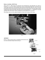
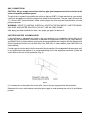
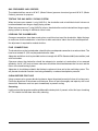
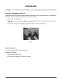
INSTALLATION &
OPERATION MANUAL
HGB(M) AND GHCBS
GAS CHARBROILERS
MODEL
HGB34
HGB50
HGB60
HGB71
HGB34M
HGB50M
HGB60M
HGB71M
GHCB34S
GHCB51S
GHMCB34
GHMCB51
ML-27850
ML-27851
ML-27852
ML-27853
ML-27885
ML-27886
ML-27887
ML-27888
ML-52245
ML-52247
ML-52244
ML-52246
For additional information on Vulcan-Hart Company or to locate an authorized
parts and service provider in your area, visit our website at www.vulcanhart.com
U.S.A.: VULCAN-HART COMPANY, P.O. BOX 696, LOUISVILLE, KY 40201-0696, TEL. (502) 778-2791
CANADA: HOBART FOOD EQUIPMENT GROUP CANADA NORTH YORK (ONTARIO) M3A 1B1
FORM 35600 (Formerly 30851 for GHCB and 28496 for HGB) (Mar. 2003)
IMPORTANT FOR YOUR SAFETY
THIS MANUAL HAS BEEN PREPARED FOR PERSONNEL QUALIFIED TO INSTALL GAS
EQUIPMENT, WHO SHOULD PERFORM THE INITIAL FIELD START-UP AND
ADJUSTMENTS OF THE EQUIPMENT COVERED BY THIS MANUAL.
POST IN A PROMINENT LOCATION THE INSTRUCTIONS TO BE FOLLOWED IN THE
EVENT THE SMELL OF GAS IS DETECTED. THIS INFORMATION CAN BE OBTAINED
FROM THE LOCAL GAS SUPPLIER.
IMPORTANT
IN THE EVENT A GAS ODOR IS DETECTED, SHUT DOWN
UNITS AT MAIN SHUTOFF VALVE AND CONTACT THE LOCAL
GAS COMPANY OR GAS SUPPLIER FOR SERVICE.
FOR YOUR SAFETY
DO NOT STORE OR USE GASOLINE OR OTHER FLAMMABLE
VAPORS OR LIQUIDS IN THE VICINITY OF THIS OR ANY
OTHER APPLIANCE.
WARNING: IMPROPER INSTALLATION, ADJUSTMENT,
ALTERATION, SERVICE OR MAINTENANCE CAN CAUSE
PROPERTY DAMAGE, INJURY OR DEATH. READ THE
INSTALLATION, OPERATING AND MAINTENANCE
INSTRUCTIONS THOROUGHLY BEFORE INSTALLING OR
SERVICING THIS EQUIPMENT.
IN THE EVENT OF A POWER FAILURE, DO NOT ATTEMPT TO
OPERATE THIS DEVICE.
MODULAR CHARBROILERS MUST BE MOUNTED ON NONCOMBUSTIBLE LEVEL SURFACE.
LEGS AND CASTERS ARE NOT AVAILABLE ON MODULAR CHARBROILERS.
© VULCAN-HART COMPANY, 2003
–2–
Installation, Operation and Care of
HGB(M) and GHCBS Gas Charbroilers
SAVE THESE INSTRUCTIONS
GENERAL
Vulcan-Hart Gas Charbroilers feature heavy-duty, cast-iron burners; input rating is 16,000 Btu per
burner. Each burner is controlled by an adjustable gas valve. Baffles suspended beneath the burners
reflect the heat upward, maintaining a cool zone under the burner. Special cast-alloy radiants are
located directly above each burner to maintain uniform temperature. Radiants are easily removed for
cleaning when cool.
Heavy-duty, cast-iron top grates (5 5/16" wide) (135 mm) are reversible to allow all or part of the cooking
grid surface to be level or sloped. Grooves, cast in the top grates, permit fat runoff and reduce flaring
when tilted toward the front.
The gas control valves can be adjusted to provide ideal sectional broiling results.
HGB AND GHCB SERIES CHARBROILERS
Model
Width (inches) (mm)
Number of Burners
Btu Input Rating
HGB34(M)/GHCB34S
34 (864)
6
96,000
HGB50(M)
50 (1270)
9
144,000
GHCB51S
51 (1295)
9
144,000
HGB60(M)
60 5/8 (1539)
12
192,000
HGB71(M)
71 3/8 (1814)
14
224,000
Large grease drawers (removable for cleaning) are below the cool zone for reduced smoking.
FEATURES AND FINISH OPTIONS
Feature
Cast Iron
Stainless Steel
Burners
Std.
N.A.
Top Grates
Std.
N.A.
Grease Drawer Front
N.A.
Std.
Front Control Panel
N.A.
Std.
Adjustable 6" (152 mm) Legs
N.A.
Opt. (HGB and GHCBS)
Storage Cabinet, Front
N.A.
Std. (HGB and GHCBS)
–3–
ACCESSORIES
•
Stainless steel splasher guard (HGB and HGBM only)
•
12" work shelf (HGB and HGBM only)
•
Four swivel casters (HGB and GHCBS only)
•
Griddle plate 18" D x 133/4" W x 1/2" Thk. (HGB and HGBM only)
•
Banking kit—joins any two charbroilers together
•
Grate lifter
•
Rod grate (1/2" steel rod on 3/4" centers) in lieu of cast-iron grate
•
Rod grate scraper
•
11/4" and 3/4" gas flex hose and quick disconnect 4' and 5' (GHCBS)
•
Flanged stainless steel feet (GHCBS)
•
•
•
3
/4" gas pressure regulator (specify gas type, nat. or LP) (GHCBS)
11/4" gas pressure regulator (specify gas type, nat. or LP) (GHCBS)
3
/4" gas shutoff valve (GHCBS)
•
11/4" gas shutoff valve (GHCBS)
•
Manifold union wrench (GHCBS)
INSTALLATION
Before installing, verify that the type of gas (natural or propane) agrees with the specifications on the
data plate located behind the lower front cover, riveted to the center support of the burner box bottom
(HGB models), or between the grease pan guides, riveted to the left corner of the lower front cover
(GHCB models). Be sure the unit is built for the installation elevation.
UNPACKING
The charbroiler was carefully inspected before leaving the factory. The transportation company
assumes full responsibility for safe delivery upon acceptance of the shipment. Immediately after
unpacking, check for possible shipping damage. If the charbroiler is found to be damaged after
unpacking, save the packaging material and contact the carrier within 7 days of delivery.
Do not use the drawers or handles to lift or move the charbroiler.
LOCATION
The equipment area must be kept free and clear of combustible substances. A minimum 2" (51 mm) of
clearance to combustibles must be provided at the rear of all broilers; no side clearance is required for
combustibles or noncombustibles. The HGB(M) is to be installed only on noncombustible floors. The
GHCBS is suitable for installation on combustible floors.
–4–
Install the charbroiler in an area that has sufficient air supply for combustion of the gas at the burners.
Provide adequate clearance for air openings into the combustion chamber. Do not obstruct the flow of
combustion and ventilation air.
Do not permit fans to blow directly at the charbroiler and, wherever possible, avoid open windows next
to the sides or back. Avoid wall-type fans that create air cross currents within the room.
Legs
Legs (6-inch [152 mm] stainless steel) or casters are factory assembled onto the bottom of the
charbroiler as specified on order.
Casters (Optional)
Casters may be ordered either two fixed and two swivel with brake.
Modular Broilers
Models HGB34M, HGB50M, HGB60M and HGB71M must be installed on a noncombustible, level
counter or stand. No adjustment is provided.
When a modular broiler is installed on a counter, it must be sealed to the counter with an NSF-approved
sealant.
INSTALLATION CODES AND STANDARDS
Install this equipment in accordance with:
In the United States
1. State and local codes, or in the absence of local codes, with:
2. National Fuel Gas Code, ANSI-Z223.1 (latest edition), available from The American Gas
Association, Inc., 1515 Wilson Boulevard, Arlington, VA 22209.
3. National Electrical Code ANSI/NFPA70 (latest edition) (if applicable).
In Canada
1. Local codes.
2. CSA Standard C22.2 No. 3 Electrical Features of Fuel Burning Equipment (latest edition).
3. CAN/CGA-B149.1 National Fuel Gas Code (latest edition), available from The Canadian Gas
Association, 178 Rexdale Rd., Etobicoke, Ontario, Canada M9W 1R3.
For an appliance equipped with casters, instructions that (1) the installation shall be made with a
connector that complies with the Standard for Connectors for Movable Gas Appliances, ANSI Z21.69
or Connectors for Moveable Gas Appliances, CAN/CGA-6.16, and a quick-disconnect device that
complies with the Standard for Quick-Disconnect Devices for Use With Gas Fuel, ANSI Z21.41 or
Quick Disconnect Devices for Use with Gas Fuel, CAN1-6.9, (2) adequate means must be provided
to limit the movement of the appliance.
–5–
Battery Installation (GHCB Only)
Since January 5, 1998, Vulcan-Hart appliances have changed from using Stockham gas unions to
Ward (Fig. 1). If you are installing a new battery range to an existing field appliance, the union on the
existing field appliance must be checked against the union being used on the new range. The union
manufacturer's name around the face surface of the union nut must match. If the new range has been
shipped using a Ward union and the old appliance has something different—i.e., Stockham—it must be
replaced with a Ward union. Failure to replace this union could result in a gas leak.
Extra Ward unions must be ordered through the Vulcan-Hart Company Parts Depot.
Fig. 1
ASSEMBLY
Burners, radiants and top grates are shipped inside the cabinet and
must be assembled during installation (Fig. 2).
Fig. 2
–6–
GAS CONNECTIONS
CAUTION: All gas supply connections and any pipe joint compound must be resistant to the
action of liquefied petroleum gases.
The gas inlet is located at the middle rear (offset to right on HGB71). Codes require that a gas shutoff
valve (not included) be installed in the gas line ahead of the charbroiler. The gas supply line must be
11/4" (32 mm) NPT (inside diameter). Make sure the pipes are clean and free of obstructions, dirt and
piping compound.
WARNING: PRIOR TO LIGHTING, CHECK ALL JOINTS IN THE GAS SUPPLY LINE FOR LEAKS.
USE SOAP AND WATER SOLUTION. DO NOT USE AN OPEN FLAME.
After piping has been checked for leaks, fully purge gas pipes to remove air.
CASTER-EQUIPPED CHARBROILERS
If the charbroiler is equipped with casters, the gas connector (not supplied by Vulcan-Hart) must
comply with the Standard for Connectors of Movable Gas Appliances, ANSI-Z21.69 (latest edition),
and CAN/CGA-6.16 (latest edition) and a quick-disconnect device that complies with the Standard for
Quick-Disconnect Devices for Use With Gas Fuel, ANSI-Z21.41 (latest edition) and CAN/CGA1-6.9
(latest edition).
Provide a gas line strain relief to limit movement of the charbroiler. Do not depend on the connector and/
or any quick-disconnect device or its associated piping to limit the appliance movement. Attach the
strain relief to the rear of the charbroiler (Fig. 3).
Fig. 3
If it is necessary to disconnect the strain relief, turn off the gas supply before disconnection.
Reconnect the strain relief before turning the gas supply on and returning the unit to its installation
position.
–7–
GAS PRESSURES AND ORIFICES
The standard orifices are set at 6" W.C. (Water Column) pressure for natural gas and 10" W.C. (Water
Column) pressure for propane.
TESTING THE GAS SUPPLY PIPING SYSTEM
When test pressures exceed 1/2 psig (3.45 kPa), the charbroiler and an individual shutoff valve must
be disconnected from the gas supply piping system.
When test pressures are 1/2 psig (3.45 kPa) or less, the charbroiler must be isolated from the gas supply
piping system by closing its individual shutoff valve.
LEVELING THE CHARBROILER
Once gas connections have been made, place a spirit level on top of the charbroiler. Adjust the legs
to make sure that the charbroiler is level front to back and side to side in the final installed position.
No adjustment is required for modular broilers.
FLUE CONNECTIONS
The charbroiler must be located under a hood that has an adequate connection to an exhaust duct. The
hood must extend 6" (152 mm) beyond charbroiler sides.
Adequate ventilation must be provided and must comply with NFPA Standard #96 (latest edition) and
with local codes.
Clearance above the charbroiler should be adequate for products of combustion to be removed
efficiently. An 18" (457-mm) minimum clearance should be maintained between the flue vent and the
filters of the hood venting system.
Adequate air should be provided in the kitchen to replace air taken out by the ventilating system. This
will prevent charbroiler function from being affected by a reduced atmospheric pressure.
CLEAN BEFORE FIRST USE
Using a noncorrosive, grease-dissolving cleaner, clean the protective metal oils from all surface parts.
Follow the directions of the cleaner manufacturer. Rinse all parts thoroughly and wipe dry with a soft
clean cloth. Reseason cast-iron parts immediately to prevent rusting.
Seasoning
Lightly season the top grates and the griddle and the backsplash, if present, with a thin layer of cooking
oil. This should also be done after every cleaning.
–8–
OPERATION
WARNING: HOT PARTS CAN CAUSE BURNS. USE CARE WHEN OPERATING THE BROILER.
LIGHTING THE MANUAL GAS PILOT
Adjustment of the pilot light must be performed by a qualified Vulcan-Hart installation or service person.
The flame adjustment must be made at the time of installation.
1. Turn main gas supply ON.
2. Wait 30 seconds and, using a lighted taper, light the pilots. The pilot for each burner must be lit
(Fig. 4).
3. If pilot fails to light, turn main gas supply OFF. Wait 5 minutes and repeat.
Fig. 4
Nightly Shutdown
Turn burner valves OFF; pilots will remain lit.
Complete Shutdown
1. Turn burner valves OFF.
2. Turn main gas supply OFF; pilots will go out.
–9–
CONTROLS (FIG. 5) – HGB(M) BROILERS
OFF
—
Horizontal when off.
ON
—
Turn valve handle counterclockwise 90 degrees so it is vertical to open the burner
gas valve completely. Adjust the valve between OFF and ON positions to moderate
the heat.
Fig. 5
CONTROLS (FIG. 6) – GHCBS BROILERS
OFF
—
Turn the knob to the right.
LO
—
Turn the knob to the left.
HI
—
Turn the knob straight up to the 12-o'clock position.
The burner heat may be controlled by turning the valve knob anywhere between the OFF and LO
positions. The burner heat will be more intense between OFF and HI and less intense between HI and
LO.
Fig. 6
Preheat – HGB(M) and GHCBS Broilers
Turn burners fully on for 20 to 25 minutes to allow the broiler to preheat. Valves should be turned to a
lower position to maintain grid temperature between 525°F and 625°F (274°C and 330°C) for optimum
broiling.
CAUTION: Leaving the valves fully on beyond the recommended preheat time will produce grid
temperatures above 1000°F (538°C), which can cause radiants to warp.
Positioning the Top Grates
The top grates have two positions. With one side up, the grids are horizontal (flat). With the other side
up, the grates slope toward the front. Use the sloped grate for most broiling to allow the groove on each
side of the grid bars to catch the melted fat and allow it to flow to the trough in front. The grease will then
flow through an opening to the grease drawer.
Do not allow the meat being broiled to catch fire as this results in a poor flavor. Fatty meats may require
reduced temperatures to minimize flames.
– 10 –
CLEANING
•
Keep the broiler clean.
•
Clean the grate grooves with the wire brush provided.
•
Empty the grease drawer frequently.
Top Grates
Clean the top grates daily on both the top and bottom surfaces with a good wire brush or burlap or other
grease-absorbing material to remove spillover, grease and so forth before it burns in. Avoid a crust on
the top of the grill: It looks unsightly and slows cooking speed (scrape off if necessary). Burn off grates
at full input after cleaning. Season grates before cooking, see Seasoning on page 8.
Burner Radiants
To prevent continuous smoking, keep the charbroiler clean. Never allow grease or fat to accumulate.
Clean burner radiants daily with a good wire brush. The radiants may be cleaned in place or removed
for a more thorough cleaning. Steel wool may be used for more stubborn spots.
Grease Trough and Drawer
Empty and clean the grease trough, and drain the drawer thoroughly at least once every day.
Exterior Surfaces
Clean all exposed surfaces of the entire charbroiler thoroughly at the end of each day. Stainless steel
may be cleaned with a damp cloth; stubborn soil may be removed with detergent and warm water.
– 11 –
MAINTENANCE
WARNING: HOT PARTS CAN CAUSE BURNS. USE CARE WHEN MAINTAINING THE BROILER.
BURNERS
If, after a period of satisfactory operation, burner flame characteristics should change or length of flame
should be reduced, burner ports may have become restricted. Burners should be cleaned at least every
60 days and more often if required. To clean burners, remove and boil in a strong solution of lye water
for about 15 minutes. Ports can be opened with a sharp-pointed instrument or proper-sized drill bit. Be
careful not to increase the size of the burner ports.
If the mixer openings or pilot orifices need cleaning, contact your Vulcan gas service technician. This
should be done at least every 6 months and more often if necessary.
SERVICE AND PARTS INFORMATION
To obtain service and parts information concerning this oven, contact the nearest service agent or call
(800) 298-1862 in the U.S.A. or (800) 444-4764 in Canada.
FORM 35600 (Mar. 2003)
– 12 –
PRINTED IN U.S.A.