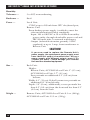
1
Customer Support Information:
FREE tech support 24 hours a day, 7 days a week: Call 724-746-5500 or fax 724-746-0746.
Mailing address: Black Box Corporation, 1000 Park Dr., Lawrence, PA 15055-1018
World-Wide Web: www.blackbox.com • E-mail: [email protected]
© Copyright 2000. Black Box Corporation. All rights reserved.
dule
l Mo
Loca
odule
ote M
Rem
Interconnect
Interconnect
From CPU or ServSwitch
From CPU or ServSwitch
MICRO-1M3
Interconnect
DECEMBER 2000
dule
l Mo
Loca
ACU3001A
ACU3009A
THE SERVSWITCH™ FAMILY
Welcome to the ServSwitchTM Family!
Thank you for purchasing a BLACK BOX® ServSwitch™ Brand CAT5 KVM
Extender model! We appreciate your business, and we think you’ll appreciate the
many ways that your enhanced keyboard/video/mouse system will save you money,
time, and effort.
That’s because our ServSwitch family is all about breaking away from the
traditional, expensive model of computer management. You know, the one-sizefits-all-even-if-it-doesn’t model that says, “One computer gets one user station, no
more, no less.” Why not a single user station (monitor, keyboard, and mouse) for
multiple computers—even computers of different platforms? Why not a pair of
user stations, each of which can control multiple computers? Why not multiple
user stations for the same computer?
With our ServSwitch products, there’s no reason why not. We carry a broad line
of robust solutions for all these applications. Do you have just two PCs, and need
an economical alternative to keeping two monitors, keyboards, and mice on your
desk? Or do you need to share dozens of computers, including a mix of IBM® PC,
RS/6000®, Apple® Macintosh®, Sun Microsystems®, and SGI® compatibles among
multiple users with different access levels? Does your switch have to sit solidly on a
worktable and use regular everyday cables? Or does it have to be mounted in an
equipment rack and use convenient many-to-one cables? No matter how large or
small your setup is, no matter how simple or how complex, we’re confident we
have a ServSwitch system that’s just right for you.
The ServSwitch™ family from Black Box—the one-stop answer for all your KVMswitching needs!
*
This manual will tell you all about your new ServSwitch™ Brand CAT5 KVM
Micro Extender, including how to install, operate, and troubleshoot it. For an
introduction to the Micro Extender, see Chapter 2. The Micro Extender product
codes covered in this manual are:
ACU3001A
ACU3009A
1
SERVSWITCH™ BRAND CAT5 KVM MICRO EXTENDER
TRADEMARKS USED IN THIS MANUAL
BLACK BOX and the
logo are registered trademarks, and ServSwitch, Matrix
ServSwitch, ServSwitch Affinity, ServSwitch Duo, ServSwitch Multi, ServSwitch
Ultra, ServSwitch Wizard, ServSwitch Wizard Pro, ServManager, ServSelect, and
ServShare are trademarks, of Black Box Corporation.
Apple and Macintosh are registered trademarks of Apple Computer, Inc.
IBM, PC/AT, PS/2, and RS/6000 are registered trademarks, and PC/XT is a
trademark, of International Business Machines Corporation.
Microsoft, IntelliMouse, Windows, and Windows NT are registered trademarks or
trademarks of Microsoft Corporation in the United States and/or other
countries.
Sun Microsystems is a registered trademark of Sun Microsystems, Inc. in the
United States and other countries.
Any other trademarks mentioned in this manual are acknowledged to be the property of the
trademark owners.
2
FCC/IC STATEMENTS
FEDERAL COMMUNICATIONS COMMISSION AND INDUSTRY CANADA
RADIO-FREQUENCY INTERFERENCE STATEMENTS
This equipment generates, uses, and can radiate radio-frequency energy and if not
installed and used properly, that is, in strict accordance with the manufacturer’s
instructions, may cause interference to radio communication. It has been tested
and found to comply with the limits for a Class A computing device in accordance
with the specifications in Subpart J of Part 15 of FCC rules, which are designed to
provide reasonable protection against such interference when the equipment is
operated in a commercial environment. Operation of this equipment in a
residential area is likely to cause interference, in which case the user at his own
expense will be required to take whatever measures may be necessary to correct the
interference.
Changes or modifications not expressly approved by the party responsible for
compliance could void the user’s authority to operate the equipment.
Shielded PC-equipment cables must be used with this equipment to maintain
compliance with radio frequency energy emission regulations and ensure a suitably
high level of immunity to electromagnetic disturbances.
This digital apparatus does not exceed the Class A limits for radio noise emission from digital
apparatus set out in the Radio Interference Regulation of Industry Canada.
Le présent appareil numérique n’émet pas de bruits radioélectriques dépassant les limites
applicables aux appareils numériques de la classe A prescrites dans le Règlement sur le
brouillage radioélectrique publié par Industrie Canada.
3
SERVSWITCH™ BRAND CAT5 KVM MICRO EXTENDER
EUROPEAN UNION DECLARATION OF CONFORMITY
This equipment complies with the requirements of the European EMC Directive
89/336/EEC with respect to the EN55022 (Class B), EN50082-1, and EN60555-2
standards, as well as the Low Voltage Directive.
4
NOM STATEMENT
NORMAS OFICIALES MEXICANAS (NOM)
ELECTRICAL SAFETY STATEMENT
INSTRUCCIONES DE SEGURIDAD
1. Todas las instrucciones de seguridad y operación deberán ser leídas antes de
que el aparato eléctrico sea operado.
2. Las instrucciones de seguridad y operación deberán ser guardadas para
referencia futura.
3. Todas las advertencias en el aparato eléctrico y en sus instrucciones de
operación deben ser respetadas.
4. Todas las instrucciones de operación y uso deben ser seguidas.
5. El aparato eléctrico no deberá ser usado cerca del agua—por ejemplo, cerca
de la tina de baño, lavabo, sótano mojado o cerca de una alberca, etc.
6. El aparato eléctrico debe ser usado únicamente con carritos o pedestales que
sean recomendados por el fabricante.
7. El aparato eléctrico debe ser montado a la pared o al techo sólo como sea
recomendado por el fabricante.
8. Servicio—El usuario no debe intentar dar servicio al equipo eléctrico más allá
a lo descrito en las instrucciones de operación. Todo otro servicio deberá ser
referido a personal de servicio calificado.
9. El aparato eléctrico debe ser situado de tal manera que su posición no
interfiera su uso. La colocación del aparato eléctrico sobre una cama, sofá,
alfombra o superficie similar puede bloquea la ventilación, no se debe colocar
en libreros o gabinetes que impidan el flujo de aire por los orificios de
ventilación.
10. El equipo eléctrico deber ser situado fuera del alcance de fuentes de calor
como radiadores, registros de calor, estufas u otros aparatos (incluyendo
amplificadores) que producen calor.
11. El aparato eléctrico deberá ser connectado a una fuente de poder sólo del
tipo descrito en el instructivo de operación, o como se indique en el aparato.
5
SERVSWITCH™ BRAND CAT5 KVM MICRO EXTENDER
12. Precaución debe ser tomada de tal manera que la tierra fisica y la polarización
del equipo no sea eliminada.
13. Los cables de la fuente de poder deben ser guiados de tal manera que no
sean pisados ni pellizcados por objetos colocados sobre o contra ellos,
poniendo particular atención a los contactos y receptáculos donde salen del
aparato.
14. El equipo eléctrico debe ser limpiado únicamente de acuerdo a las
recomendaciones del fabricante.
15. En caso de existir, una antena externa deberá ser localizada lejos de las lineas
de energia.
16. El cable de corriente deberá ser desconectado del cuando el equipo no sea
usado por un largo periodo de tiempo.
17. Cuidado debe ser tomado de tal manera que objectos liquidos no sean
derramados sobre la cubierta u orificios de ventilación.
18. Servicio por personal calificado deberá ser provisto cuando:
A: El cable de poder o el contacto ha sido dañado; u
B: Objectos han caído o líquido ha sido derramado dentro del aparato; o
C: El aparato ha sido expuesto a la lluvia; o
D: El aparato parece no operar normalmente o muestra un cambio en su
desempeño; o
E: El aparato ha sido tirado o su cubierta ha sido dañada.
6
TABLE OF CONTENTS
Contents
Chapter
Page
1.
Quick Start Guide ...................................................................................... 9
2.
Specifications ........................................................................................... 10
3.
Introduction ............................................................................................. 13
3.1 Compatibility ..................................................................................... 14
3.2 Key Features ...................................................................................... 15
4.
Checklist of System Components ............................................................
4.1 The Complete Package .....................................................................
4.2 The Cables You’ll Need ....................................................................
4.2.1 To Connect a CPU to the Local Unit ....................................
4.2.2 To Connect a ServSwitch Family KVM Switch to the
Local Unit .............................................................................
4.2.3 To Connect a Monitor, Keyboard, and Mouse to the
Remote Unit or to the User Ports on the
Dual-Access Local Unit ........................................................
4.2.4 To Connect a ServSwitch Family KVM Switch to the
Remote Unit or to the User Ports on the
Dual-Access Local Unit ........................................................
4.2.5 To Connect the Local Unit to the Remote Unit ...................
16
16
16
17
17
19
19
21
5.
Configuration ........................................................................................... 22
5.1 DIP Switch 1: Video Distance ........................................................... 22
5.2 DIP Switch 2: Scroll-Lock Handling ................................................ 22
6.
Installation ................................................................................................
6.1 Test-Placing the Extender System (Optional) ................................
6.2 Attaching Devices ..............................................................................
6.2.1 Attaching a CPU to the Local Unit’s CPU Port ....................
6.2.2 Attaching a ServSwitch Family KVM Switch to the
Local Unit’s CPU Port .........................................................
6.2.3 Attaching a Monitor, Keyboard, and Mouse to the
Remote Unit or Dual-Access Local Unit .............................
6.2.4 Attaching a ServSwitch Family KVM Switch to the
Remote Unit or to the Dual-Access Local Unit’s
User Ports ..............................................................................
6.3 Finishing Your Installation ...............................................................
23
23
23
24
24
26
27
29
7
SERVSWITCH™ BRAND CAT5 KVM MICRO EXTENDER
Contents (continued)
Chapter
7.
8.
Page
Operation .................................................................................................
7.1 Keyboard and Mouse Emulation .....................................................
7.2 Normal Operation and Keyboard Typematic Rate .........................
7.3 The Scroll-Lock Reset .......................................................................
7.4 Correcting the PS/2 Mouse If It Gets Out of Sync .........................
7.5 Shared User Access (Dual-Access Systems Only):
The Inactivity Timeout and Private Mode ....................................
31
31
31
32
32
Troubleshooting ......................................................................................
8.1 Common Problems ...........................................................................
8.1.1 Keyboard ..................................................................................
8.1.2 Mouse .......................................................................................
8.1.3 Both Keyboard and Mouse .....................................................
8.1.4 Video ........................................................................................
8.1.5 Power .......................................................................................
8.2 General Questions About the Micro Extender ...............................
8.3 Calling Black Box ..............................................................................
8.4 Shipping and Packaging ...................................................................
36
36
36
37
38
39
41
42
44
44
34
Appendix: Cable Pinning/Pairing ................................................................. 45
8
CHAPTER 1: Quick Start Guide
1. Quick Start Guide
When you configure the ServSwitch™ Brand CAT5 KVM Micro Extender, you only
need to answer two questions:
• How far will the CAT5 cabling run between the Extender’s Local and Remote
Units? If will be 25 m (80 ft.) or less, you don’t need to set anything. If it will be
25 to 50 m (80 to 160 ft.), move DIP switch 1 on the bottom of the Remote
Unit to the DOWN (ON) setting.
• Do you need the Scroll Lock key for anything? If not, you don’t need to set
anything; you’ll be able to press Scroll Lock to reset the Extender. If you need
Scroll Lock to control your hardware or software, move DIP switch 2 on the
bottom of the Remote Unit to the DOWN (ON) setting.
To install your Extender system, refer to the illustration below. A basic
ACU3009A (Dual-Access) installation with a CPU and monitors, keyboards, and
mice is shown; ACU3001A Single-Access systems will be set up exactly the same way,
except that they won’t include the local keyboard, monitor, and mouse.
Use the included extension cable to attach the CPU to the Local Unit. Plug the
remote keyboard, monitor, mouse, and serial device directly into the Remote Unit.
In Dual-Access systems, plug the local keyboard, monitor, mouse, and serial device
directly into the Local Unit. Connect the Local and Remote Units with straightpinned four-pair solid-core CAT5 cable (not CAT5e, Level 6, etc.). Power the
Remote Unit with its included power supply. For more information, or if your
installation includes any KVM switches, refer to Chapter 6.
Local monitor, keyboard, and mouse
(ACU3009A Dual-Access systems only)
Local
Unit
Local CPU
Included
KVMextension
cable
CAT5
cable
Remote
Unit
Remote monitor,
keyboard, and mouse
9
SERVSWITCH™ BRAND CAT5 KVM MICRO EXTENDER
2. Specifications
Cable Required — Between Local and Remote Units: Category 5 solid
unshielded or shielded twisted pair (UTP or STP),
wired to the EIA/TIA-568A or (preferred) -568B
standard, terminated with RJ-45 male connectors; for
pinning/pairing, see the Appendix
Compliance —
CE Class B; FCC Part 15 Subpart J Class A, IC Class/
classe A
Compatibility —
Video: VGA, SVGA, XGA, XGA-2, or RGsB (sync on
green), although if your system has monitor ID-bit
requirements, you might need to call Black Box for
technical support;
Keyboard: IBM PC/AT or PS/2 compatible (PC/AT
types require connector adapter);
Mouse: IBM PS/2 compatible two-button, Microsoft
IntelliMouse, or Logitech PS/2 compatible 3-button
Interfaces —
To monitor: VGA;
To keyboard and mouse: IBM PS/2 compatible;
To/from CPU and between Units:
Proprietary composites of the above
Resolution —
Up to 1280 x 1024
Video I/O
Signal Levels —
0.7 Volts peak-to-peak
Video
Compensation —
For short- or long-distance (user-switchable)
Synchronization — H/V or composite, TTL signal levels; sync polarity is
preserved
Video Coupling — DC
10
CHAPTER 2: Specifications
Maximum
Distance —
5 m (15 ft.) from the Local Unit to the attached CPU or
KVM switch;
5 m (15 ft.) from the Remote Unit to the attached
monitor, keyboard, and mouse or KVM switch;
50 m (160 ft.) between Local and Remote Units
Dual-Access (ACU3009A) model only: 5 m (16 ft.) from
the Local Unit to the attached keyboard, mouse, and
monitor
NOTE
With high-quality cables, it might be possible to run
farther than 5 m (15 ft.) from the Extender to attached
equipment.
User Controls —
Remote Unit: (1) Bottom-mounted 2-position DIP switch
for video distance (cable length)
Indicator —
Local Unit: Right-side-mounted LED for power and link
integrity
Connectors —
Local Unit:
(1) Right-side-mounted RJ-45 female for local/remote
interconnection;
(1) Left-side-mounted DB25 female for video input
from, and keyboard/mouse output to, computer;
Left-side-mounted on Dual-Access (ACU3009A) model
only:
(1) HD15 female for video output to local monitor;
(2) 6-pin mini-DIN female for input from local
keyboard and mouse
Remote Unit:
Right-side-mounted:
(1) RJ-45 female for local/remote interconnection;
(1) 2.5-mm center-positive barrel jack for power;
Left-side-mounted:
(1) HD15 female for video output to monitor;
(2) 6-pin mini-DIN female for input from keyboard
and mouse
Temperature
Tolerance —
32 to 104˚ F (0 to 40˚ C)
11
SERVSWITCH™ BRAND CAT5 KVM MICRO EXTENDER
Humidity
Tolerance —
5 to 90% noncondensing
Enclosure —
Steel
Power —
Local Unit:
5 VDC at up to 120 mA from CPU’s keyboard port;
Remote Unit:
From desktop power supply (certified to meet the
relevant international safety standards):
Input: 100 to 240 VAC at 50 to 60 Hz from utilitypower outlet, through detachable power cord and
IEC 320 male inlet, to external transformer;
Output (isolated from mains ground): 9 VDC
regulated, at up to 1 amp, from transformer to
Remote Unit
CAUTION!
If you ever need to replace the Remote Unit’s
power supply, the replacement power supply must
have identical output characteristics. Using a
power supply with different output—even if it’s
“almost the same”—could damage your Remote
Unit and the attached equipment.
Size —
Each Unit:
Height:
Remote Units, ACU3001A Local Unit: 1" (2.5 cm);
ACU3009A Local Unit: 1.7" (4.3 cm);
Feet protrude an additional 0.1" (0.2 cm) from
bottom;
Width: 4.3" (11 cm); D-shell connectors protrude an
additional 0.1" from left side;
Depth: 3.2" (8 cm); additionally, screws protrude less
than 0.1" (0.2 cm) from the front and less than 0.1"
(0.2 cm) from the back
Weight —
Remote Units, ACU3001A Local Unit: 8.3 oz. (240 g);
ACU3009A Local Unit: 13.5 oz. (390 g)
12
CHAPTER 3: Introduction
3. Introduction
By using the Local and Remote Units that together make up the ServSwitch™
Brand CAT5 KVM Micro Extender, you can place your VGA monitor, keyboard,
and mouse as far as 50 meters (160 ft.) from the PC’s CPU. The Local and Remote
Units are interconnected with a single industry-standard Category 5 UTP or STP 4pair cable. All keyboard, mouse, and video signals are fully buffered to ensure
consistent remote operation of your PC.
The Single-Access (ACU3001A) model of the Extender is designed to perform
KVM extension only. With the Dual-Access (ACU3009A) model, you can attach an
additional monitor, keyboard, and mouse to the Local Unit; the PC can then be
operated from either the local or remote user station (they share access on a “firstcome, first-served” basis—see Section 7.5).
The Micro Extender is simple to operate and works with all operating systems—
no software is required. Just connect the Units as described in Chapter 6 and
you’re ready to work!
Because the Micro Extender performs complete PS/2® keyboard and mouse
emulation, you can boot the PC without having a keyboard or mouse attached to it.
Your PC will boot even if the Extender’s Remote Unit is not powered or has no
keyboard or mouse connected to it.
13
SERVSWITCH™ BRAND CAT5 KVM MICRO EXTENDER
3.1 Compatibility
The ServSwitch Brand CAT5 KVM Micro Extender is designed to operate in
various environments and with a mix of hardware from different manufacturers.
During development, this product was extensively tested with a wide variety of
hardware. However, please note that it is impossible for us to guarantee that the
Micro Extender will interoperate correctly with every keyboard, mouse, monitor,
and motherboard variant currently on the market. If you suspect that you’re
having incompatibility problems, please call Black Box Technical Support.
In general, the Micro Extender is compatible with the following types of
equipment:
• CPU: IBM® PC/AT®, PS/2, and 100% compatible clones. These should be
desktop machines; laptops and docking stations are not supported.
• Monitor: VGA, SVGA, XGA, XGA-2, or RGsB (sync on green). Be aware that a
few monitors and graphics cards might not work with the “as is” Micro
Extender—at least in their factory-default settings—because they exchange
monitor IDs or VESA DDC (Display Data Channel) information. Call Black
Box Technical Support for help with “ID bit” problems. As for DDC, the
Extender supports it at the ACU3009A’s local user station but not at any
remote user station, so either (a) do not use a DDC monitor at your remote
station, or (b) go into your graphics card’s settings, turn DDC off, and
manually configure the card for your monitor(s).
• Keyboard: Standard (101- or 102-key) PS/2 type or enhanced PS/2 type (104or 105-key, designed for use with versions of Windows® starting with
Windows 95). Although we don’t recommend this, you might also be able to
use a PC/AT type keyboard with 5-pin DIN connectors; you’ll need adapters to
attach it and its native CPU to the Micro Extender (see the start of
Section 4.2). Some older PC/XT™ or PC/AT type autosensing keyboards
might not be compatible with the Extender. If the keyboard you want to use is
some other type or has some other type of connector, call Black Box for
technical support.
For information about keyboard typematic support, see Section 7.2.
• Mouse: Standard PS/2 type, Microsoft® IntelliMouse® compatible, or
Logitech™ 3-button PS/2 compatible mouse; the CPU should have standard
PS/2 type mouse ports. If your PC doesn’t have a PS/2 style mouse port, you’ll
need a special adapter to attach the PS/2 mouse cable to one of the PC’s serial
ports (see the start of Section 4.2). The Extender is not compatible with serial
mice or bus mice. If a mouse you want to attach is some other type or has some
other type of connector, call Black Box Technical Support.
14
CHAPTER 3: Introduction
3.2 Key Features
The ServSwitch Brand CAT5 KVM Micro Extender has a number of useful features
which contribute to the transparent remote operation of your PC. Some of the
more important ones are:
• Distance up to 50 m (160 ft.)
Operate your PC from the next room or all the way down the hall.
• Adjustable video equalization
Compensates for the loss of image quality caused by the signal passing through
more than 25 m (80 ft.) of cable.
• Fully buffered signals
Remote operation of the PC is consistently smooth and transparent.
• Intelligent PS/2 keyboard and mouse emulation
With this, the PC boots and operates correctly under most circumstances, and
you can freely detach and reconnect the keyboard and mouse as necessary
(the Micro Extender automatically initializes the keyboard and mouse as soon
as it detects that you’ve reattached them).
• Microsoft IntelliMouse compatibility
Use this and compatible “wheel mice” with confidence.
• Dual-Access model also supports a local station
With the Dual-Access (ACU3009A) model, you can operate the PC either
locally or remotely (but not both at the same time).
We recommend that you read the remainder of this manual before you install the
Micro Extender in order to fully familiarize yourself with the system.
15
SERVSWITCH™ BRAND CAT5 KVM MICRO EXTENDER
4. Checklist of System Components
4.1 The Complete Package
These items should be included with your ServSwitch™ Brand CAT5 KVM Micro
Extender package (please contact Black Box right away if any are missing or
damaged):
• (1) Micro Extender Local Unit.
• (1) Micro Extender Remote Unit.
• (1) 9-VDC 1-amp power-supply transformer and output cord.
• (1) Power-supply input cord suitable for your country or region.
• (1) 1-m (3.3-ft.) KVM-extension cable (runs from CPU to Local Unit) with a
DB25 male connector at the Unit end and an HD15 male connector and two
6-pin mini-DIN male connectors at the CPU end. (If your system uses 5-pin DIN
keyboard connectors, see the start of Section 4.2 for how you’ll connect it.)
• (1) Copy of this manual.
4.2 The Cables You’ll Need
If you are using the ServSwitch™ Brand CAT5 KVM Micro Extender to get greater
distance between a CPU and a VGA monitor, PS/2 keyboard, and PS/2 mouse,
your Micro Extender package should have included everything you’ll need except
for your Unit-interconnection cable. Read Sections 4.2.1, 4.2.3, and 4.2.5 carefully,
then skip ahead to Chapter 5.
If you are using the Micro Extender to get greater distance between a ServSwitch
family KVM switch and a CPU, a user station (monitor/keyboard/mouse), or a
compatible switch, you might need additional non-included cabling. Read the
relevant sections on the next few pages, from Section 4.2.1 through Section 4.2.5.
If you are using any equipment with PC/AT style connectors, you might also
need some combination of these adapters:
• To attach a CPU or KVM switch with a 5-pin DIN female keyboard connector
to the Local Unit: A keyboard-port adapter such as product code FA211.
• To attach a CPU or KVM switch with an RS-232 serial DB9 male mouse connector
to the Local Unit: A mouse-port adapter such as product code AC244A. (If the
mouse port is DB25 rather than DB9, you’ll also need an FA521A serial adapter.)
• To attach a keyboard or KVM switch with a 5-pin DIN male keyboard connector
to the Local or Remote Unit: A keyboard adapter such as product code FA212.
16
CHAPTER 4: Checklist of System Components
4.2.1 TO CONNECT A CPU TO THE LOCAL UNIT
You’ll use the three-in-one KVM-extension cable included with the ServSwitch™
Brand CAT5 KVM Micro Extender.
4.2.2 TO CONNECT A SERVSWITCH FAMILY KVM SWITCH TO THE LOCAL UNIT’S CPU PORT
You would do this to extend the distance you can run from the KVM switch to a
monitor, keyboard, and mouse. (You could also do this to extend the distance you
can run between two cascaded switches, but for this to work, each switch must be
either a ServSwitch Jr. or one of the ServSwitch family models with compatible
composite interfaces listed in Section 4.2.2.B.)
The Local Unit’s CPU port is the DB25 connector on the opposite end of the
Unit from the RJ-45 jack. Which cable(s) you’ll use to connect the switch to it will
depend on what type of user ports the switch model has, as detailed in the
following three subsections.
4.2.2.A Switches Whose User Ports Are a Set of Separate Interfaces
The user ports of some ServSwitch family KVM switches are a set of separate
interfaces: Each user port consists of separate interfaces/connectors for video,
keyboard, and mouse communication. At the time of this writing, some of the
important ServSwitch family models in this category are:
• ServSwitch™ Duo
• ServSwitch™ Wizard
• ServSwitch™ Wizard Pro
• ServSwitch™ Jr.
• Personal ServSwitch™
• ServSelect™
• ServSwitch™ Multi Base Unit (“local console” user port only)
To attach a user port on one of these switches to the Local Unit’s CPU port, you
can use the three-in-one KVM-extension cable included with the ServSwitch™
Brand CAT5 KVM Micro Extender.
17
SERVSWITCH™ BRAND CAT5 KVM MICRO EXTENDER
4.2.2.B Switches Whose User Ports Are Compatible Composite Interfaces
The user ports of some ServSwitch family KVM switches are composite (all-in-one)
interfaces that are compatible with the Local Unit’s CPU port. On these switches,
the user ports are DB25 connectors pinned out the same way as the DB25
connector on the Local Unit. At the time of this writing, some of the important
ServSwitch family models in this category are:
• ServSwitch™
• ServSwitch™ Ultra
• Matrix ServSwitch™
• ServSwitch™ Affinity
• ServManager™
• ServShare™
Order a ServSwitch-to-ServSwitch Expansion Cable (product code EHN284) to
attach this type of KVM-switch user port to the Local Unit’s CPU port.
4.2.2.C Switches Whose User Ports Are Incompatible Composite Interfaces
The HD62 female user ports on the ServSwitch™ Multi’s User Cards are composite
(all-in-one) interfaces that are not compatible with the Local Unit’s CPU port. This
doesn’t mean that they can’t be connected to the Local Unit’s CPU port; you’ll just
need slightly more complicated cabling.
Namely, you’ll need a ServSwitch Multi User Cable such as product code
KV2505, plus the three-to-one KVM-extension cable included with your Extender.
Refer to Section 6.2.2.C for a description of how this cabling fits together.
18
CHAPTER 4: Checklist of System Components
4.2.3 TO CONNECT A MONITOR, KEYBOARD, AND MOUSE TO THE REMOTE UNIT OR TO THE
USER PORTS ON THE DUAL-ACCESS LOCAL UNIT
You’ll be plugging the monitor, keyboard, and mouse directly into the
corresponding user ports on the Remote Unit or Dual-Access Local Unit.
4.2.4 TO CONNECT A SERVSWITCH FAMILY KVM SWITCH TO THE REMOTE UNIT OR TO THE
USER PORTS ON THE DUAL-ACCESS LOCAL UNIT
You would do this to extend the distance you can run from the KVM switch to a
CPU. (You could also do this to extend the distance you can run between two
cascaded switches, but for this to work, each switch must be one of the ServSwitch
family models with compatible composite interfaces listed in Section 4.2.4.B.)
On the Remote Unit and the Dual-Access Local Unit, the user ports are the
HD15 and 6-pin mini-DIN connectors on the opposite end of the Unit from the
RJ-45 jack. Which cable(s) you’ll use to connect the switch to it will depend on
what type of CPU ports the switch model has, as detailed in the following three
subsections.
4.2.4.A Switches Whose CPU Ports Are a Set of Separate Interfaces
The CPU ports of some ServSwitch family KVM switches are a set of separate
interfaces: Each CPU port consists of separate interfaces/connectors for video,
keyboard, and mouse communication. At the time of this writing, some of the
important ServSwitch family models in this category are:
• ServSwitch™ Duo
• ServSwitch™ Wizard
• ServSwitch™ Wizard Pro
• Personal ServSwitch™
Order individual keyboard-, video-, and mouse-extension cables (such as product
codes EVMPS03-MM for keyboard and mouse, EVNPS05-MM for video) or a
specially bonded three-to-three CPU-extension cable (product code EHN408) to
attach a KVM-switch CPU port of this type to the user ports on the Remote Unit or
Dual-Access Local Unit.
19
SERVSWITCH™ BRAND CAT5 KVM MICRO EXTENDER
4.2.4.B Switches Whose CPU Ports Are Compatible Composite Interfaces
The CPU ports of some ServSwitch family KVM switches are composite (all-in-one)
interfaces that are compatible with the CPU port on the Extender’s Local Unit. On
these switches, the CPU ports are DB25 connectors pinned out the same way as the
DB25 connectors on the Local Unit. At the time of this writing, some of the
important ServSwitch family models in this category are:
• ServSwitch™
• ServSwitch™ Ultra
• Matrix ServSwitch™
• ServSwitch™ Affinity
• ServSwitch Jr.
• ServManager™
• ServShare™
You can use the three-to-one KVM-extension cable included with your Extender to
attach a KVM-switch CPU port of this type the user ports on the Remote Unit or
Dual-Access Local Unit. If you’ve already used that cable to attach a CPU to the
Local Unit, order the same type of cable (product code EHN230) to make this
connection.
4.2.4.C Switches Whose CPU Ports Are Incompatible Composite Interfaces
The CPU ports of some ServSwitch family KVM switches are composite (all-in-one)
interfaces that are not compatible with the CPU port on the Extender’s Local Unit.
This doesn’t mean that these ports can’t be connected to the Remote Unit; you’ll
just need different cabling:
• The CPU ports on the CPU Cards of the ServSwitch Multi are HD44 female
connectors. You’ll need a ServSwitch Multi Server Cable such as product code
KV2020-R2 to attach a ServSwitch Multi CPU port to the user ports on the
Remote Unit or Dual-Access Local Unit.
• The CPU ports on the ServSelect are DB25 connectors pinned differently from
the DB25 connectors on the Local Unit. You’ll need a ServSelect Cable
(product code EHN056) to attach a ServSelect CPU port to the user ports on
the Remote Unit or Dual-Access Local Unit.
20
CHAPTER 4: Checklist of System Components
4.2.5 TO CONNECT THE LOCAL UNIT TO THE REMOTE UNIT
To interconnect the Local and Remote Units of the Micro Extender, you’ll need
industry-standard structured cabling (Category 5 UTP or STP, 4-pair) terminated
with RJ-45 plugs. This cable is not included with the Extender. Order CAT5 patch
cables such as our product code EYN737MS or CAT5 bulk cable such as our
EYN840A. The bulk cable should be terminated with high-quality RJ-45 plugs such
as those included in our FM732 25-pack.
CAUTION!
This cable must be solid-core type; stranded patch cable will give poor
results over longer distances. The pairing of the cable and pinning of its
connectors must be in accordance with EIA/TIA-568A or (preferably)
EIA/TIA-568B. (Refer to the wiring chart in the Appendix. Please note that
failure to wire the twisted pairs correctly will dramatically impair video
quality and possibly prevent correct operation.)
We don’t recommend using CAT5e cable, although it might perform well
in some applications. Avoid using “Level 6” or “Level 7” cables, or other
types of cable rated for data rates higher than 100 Mbps (bandwidths higher
than 100 MHz). This is because the wires in these cables are twisted much
more tightly than those in regular CAT5, which is great for high-speed data
but really bad for video signals.
Also, even though your network might use the same type of 4-wire
twisted-pair cabling, do not connect the Micro Extender to 10BASE-T
Ethernet devices or any other network equipment. Doing so will virtually
destroy the Extender’s circuitry and could also damage the attached
equipment.
The Micro Extender is designed for use up to a maximum cable length of 50 m
(160 ft.). At this length the video quality should be acceptable even at a screen
resolution of 1280 x 1024 pixels.
Although a single continuous length of interconnect cable is preferable, it’s
possible to operate a Micro Extender system if the Local and Remote Units are
connected through multiple patch panels. However, the more patch panels the
cable is routed through, the greater the probability that the video signal will be
degraded.
NOTE
The Micro Extender has been tested and found to work, in certain
situations, with 4-pair Category 3 cable or with four pairs of 25-pair UTP
trunk cables instead of 4-pair Category 5 cable. We do not recommend
such installations; if you want to experiment with them, do so at your
own risk.
21
SERVSWITCH™ BRAND CAT5 KVM MICRO EXTENDER
5. Configuration
There are a pair of DIP switches on the bottom of the Remote Unit of the
ServSwitch™ Brand CAT5 KVM Micro Extender. You might need to set these
differently if you are running CAT5 cable to longer distances or if you need to use
the Scroll Lock key on your keyboard for something other than an Extender reset.
5.1 DIP Switch 1: Video Distance
The Remote Unit contains video-equalization circuitry which compensates for the
loss in image quality that occurs when you drive video across cables longer than
25 m (80 ft.). If you’ll be running cable between the Micro Extender’s Units to
such distances, you need to configure the Extender for extra equalization before
you install it.
Leave DIP switch 1 in the factory-default UP (OFF) setting if you’ll be running
cable up to (but not more than) 25 m (80 ft.) between the Units. To boost the
equalization if you’ll be running cable between 25 and 50 m (80 and 160 ft.), move
DIP switch 1 to the DOWN (ON) setting.
If you are not running the cable too far but your video looks bad no matter how
you set this DIP switch, the problem is almost certainly being caused by one of two
things. First, check your interconnect-cable routing—does the cable pass close to a
motor, generator, fluorescent lights, etc.? Second, check the wiring of the
interconnect cable. Compare its pinning and pairing with those shown in the
Appendix. (Please realize that signal equalization cannot be exact; regardless of
the setting of this DIP switch, the remote video image might never appear quite as
sharp as it would appear with the monitor directly attached to the CPU.)
5.2 DIP Switch 2: Scroll-Lock Handling
Normally, pressing the Scroll Lock key on the keyboard attached to the Remote
Unit causes the Micro Extender to reset itself (see Section 7.3) or, in Dual-Access
systems, to go into Private Mode (see Section 7.5). But the Extender treats this
keypress as a command and absorbs it, so there’s no way to send Scroll Lock to the
PC or KVM switch attached to the Local Unit.
Leave DIP switch 2 in the factory-default UP (OFF) setting if Scroll Lock isn’t
necessary for your application and can continue to be used to trigger reset/Private
Mode. If you need to be able to use the Scroll Lock key for something else, move
DIP switch 2 to the DOWN (ON) setting to disable reset and Private Mode and
cause the Extender to pass Scroll Lock through to the attached PC or switch.
22
CHAPTER 6: Installation
6. Installation
To install your ServSwitch™ Brand CAT5 KVM Micro Extender system, first testplace it (if you want to) as described in Section 6.1, then attach devices as
described in Section 6.2, then finish your installation as described in Section 6.3.
6.1 Test-Placing the Extender System (Optional)
We recommend testing your Micro Extender system with a test setup confined to a
single room; that way, if any components are bad, you can find out before you run
cable halfway across your campus. If you want to do this, gather your equipment in
your test site; otherwise, place the Extender’s Local and Remote Units, and the
equipment you’ll be attaching to them, in your desired locations.
6.2 Attaching Devices
For instructions on making device connections, refer to these subsections:
• Section 6.2.1 for attaching a CPU to the Local Unit’s CPU port.
• Section 6.2.2 for attaching a KVM switch to the Local Unit’s CPU port.
• Section 6.2.3 for attaching a monitor, keyboard, and mouse to the user ports of
the Remote Unit or the Dual-Access Local Unit.
• Section 6.2.4 for attaching a KVM switch to the user ports of the Remote Unit
or the Dual-Access Local Unit.
As you attach devices to the Extender, here are some things to keep in mind:
• Use caution if you’re attaching KVM switches: Different ServSwitch family KVM
switch models use different proprietary signaling between cascaded switches.
The only ServSwitch family switch models whose cascade signals the Micro
Extenders can carry are those with a compatible composite interface (see the
list in Section 4.2.4.B), so these are the only models for which you can install a
Micro Extender between two cascaded (master and submaster) switches.
Under no circumstances should you ever try to use a Micro Extender to connect
two incompatible ServSwitch models. Having an Extender between them will
not make them compatible.
• Each powered device should be powered OFF when you attach it.
• Make sure you don’t attach your keyboard and mouse, or the keyboard and
mouse strands of any multi-stranded cable, backwards. (Fortunately, the
strands of the KVM-extension cable included with the Extender—and the
similar EHN230 cable—are fairly easy to identify: The keyboard strand is
orange and labeled with the picture of a keyboard, while the mouse strand is
green and labeled with the picture of a mouse.)
23
SERVSWITCH™ BRAND CAT5 KVM MICRO EXTENDER
6.2.1 ATTACHING A CPU TO THE LOCAL UNIT’S CPU PORT
Run the included KVM-extension cable from the Local Unit’s CPU port to the
keyboard, video, and mouse ports on your PC.
CPU
Included KVMextension cable
Local Unit
Figure 6-1. Attaching a CPU to the Local Unit’s CPU port.
6.2.2 ATTACHING A SERVSWITCH FAMILY KVM SWITCH TO THE LOCAL UNIT’S CPU PORT
The way you’ll do this will depend on what kind of user ports the KVM switch has:
multiple connectors (see Section 6.2.2.A), single connectors compatible with the
Local Unit’s (see Section 6.2.2.B), or single connectors that aren’t compatible with
the Local Unit’s (see Section 6.2.2.C). (Refer to the listings in Section 4.2.2 for
which ServSwitch family models are in which category.)
6.2.2.A Attaching a Switch with Multiple User-Port Connectors
Run the included KVM-extension cable from the Local Unit’s CPU port to the
video, keyboard, and mouse connectors of one of the KVM switch’s user ports.
ServSwitch Wizard Pro (SW648A)
(To CPUs)
Included KVMextension Cable
Local
Unit
Figure 6-2. Attaching a KVM switch with multiple user-port connectors to
the Local Unit’s CPU port.
24
CHAPTER 6: Installation
6.2.2.B Attaching a Switch with a Single Compatible User-Port Connector
Run a ServSwitch-to-ServSwitch Expansion Cable (product code EHN284) from
the Local Unit’s CPU port to one of the KVM switch’s user ports, which will be
DB25 connectors.
Regular ServSwitch
(KV3108SA-R4)
(To CPUs)
ServSwitch-toServSwitch
Expansion Cable
(EHN284)
Local
Unit
Figure 6-3. Attaching a KVM switch with a single compatible user-port
connector to the Local Unit’s CPU port.
6.2.2.C Attaching a Switch with a Single Incompatible User-Port Connector
First plug the included three-to-one KVM-extension cable into the Local Unit’s
CPU port. Then plug a User Cable designed for the KVM switch into one of the
switch’s user ports. (For the ServSwitch Multi, you could use product code
KV2505.) Connect the matching strands of the KVM-extension cable and User
Cable together as shown in Figure 6-4.
ServSwitch
Multi EXP
(KV160A-R2)
User cable KV2505
(plugs into User Card)
Included KVMextension Cable
Local Unit
Figure 6-4. Attaching a KVM switch with a single incompatible user-port
connector to the Local Unit’s CPU port.
25
SERVSWITCH™ BRAND CAT5 KVM MICRO EXTENDER
6.2.3 ATTACHING A MONITOR, KEYBOARD, AND MOUSE TO THE REMOTE UNIT OR DUALACCESS LOCAL UNIT
Plug the monitor, keyboard, and mouse directly into the matching ports on the
Remote Unit or Dual-Access Local Unit.
Remote Unit
Figure 6-5. Attaching user equipment to the Remote Unit.
26
CHAPTER 6: Installation
6.2.4 ATTACHING A SERVSWITCH FAMILY KVM SWITCH TO THE REMOTE UNIT OR TO THE
DUAL-ACCESS LOCAL UNIT’S USER PORTS
The way you’ll do this will depend on what kind of CPU ports the Switch has:
multiple connectors (see Section 6.2.4.A), single connectors compatible with the
Local Unit’s (see Section 6.2.4.B), or single connectors that aren’t compatible with
the Local Unit’s (see Section 6.2.4.C). (Refer to the listings in Section 4.2.4 for
which switch models are in which category.)
6.2.4.A Attaching a Switch with Multiple CPU-Port Connectors
Run extension cabling from the monitor, keyboard, and mouse connectors on the
Remote Unit or Dual-Access Local Unit to the matching CPU-port connectors on
the KVM switch. This extension cabling can be individual keyboard-, video-, and
mouse-extension cables (product codes EVMPS03-MM for keyboard and mouse,
EVNPS05-MM for video), but we recommend our specially bonded three-to-three
CPU-extension cable (product code EHN408):
• If you’re using individual extension cables, run the video-extension cable
between the two video/monitor ports, the keyboard-extension cable between
the two keyboard ports, and the mouse-extension cable between the two
mouse ports.
• If you’re using one of our three-to-three bonded extension cables, run the
cable’s video strand between the two video/monitor ports, the cable’s
keyboard strand between the two keyboard ports, and the cable’s mouse strand
between the two mouse ports, as shown in Figure 6-6.
ServSwitch Wizard Pro (SW644A)
Remote Unit
(To master Switch or
monitor, keyboard,
and mouse)
EHN408
Figure 6-6. Attaching a KVM switch with multiple CPU-port connectors to
the Remote Unit.
27
SERVSWITCH™ BRAND CAT5 KVM MICRO EXTENDER
6.2.4.B Attaching a Switch with a Single Compatible CPU-Port Connector
Run the included KVM-extension cable from one of the switch’s CPU ports to the
monitor, keyboard, and mouse ports on the Remote Unit or Dual-Access Local
Unit. If you’ve already used the included extension cable to attach a CPU or switch
to the Local Unit’s CPU port, use a similar cable such as product code EHN230.
Regular ServSwitch (KV3108SA-R4)
Expansion Cable to
master Switch or
User Cable to monitor,
keyboard, and mouse
Included KVMextension cable
or EHN230
Remote Unit
Figure 6-7. Attaching a KVM switch with single compatible CPU-port
connector to the Remote Unit.
6.2.4.C Attaching a Switch with Single Incompatible CPU-Port Connectors
Get a CPU cable or server cable designed for the switch, then run it from one of
the switch’s CPU ports to the monitor, keyboard, and mouse ports on the Remote
Unit or Dual-Access Local Unit.
ServSwitch Multi EXP
(KV160A-R2)
User cable from
User Card to monitor,
keyboard, and mouse
Remote Unit
KV2020-R2
(plugs into
CPU Card)
Figure 6-8. Attaching a KVM switch with a single incompatible CPU-port
connector (ServSwitch Multi shown) to the Remote Unit.
28
CHAPTER 6: Installation
6.3 Finishing Your Installation
To finish installing your Micro Extender system after attaching devices to it as
described in Section 6.2, take these steps:
1. Attach the output cord of the Remote Unit’s power supply to the Unit’s
power jack. Then plug the IEC 320 end of the power supply’s input cord into
the IEC 320 inlet on the power supply’s transformer. Finally, plug the other
end of the input cord into a utility (mains) power outlet. The Remote Unit
should power up immediately; it has no ON/OFF switch. (If the Remote Unit
is in the location you want it to be, you can leave it plugged in and powered
up more or less indefinitely.)
CAUTION!
If you ever need to replace the power supply of the Remote Unit, the
replacement power supply must have identical output characteristics
(see the “Power” specification in Chapter 2). Using a power supply with
different output—even if it’s “almost the same”—could damage your
equipment.
2. Power ON the monitor or KVM switch attached to the Remote Unit. DualAccess systems: Power ON any monitor or switch attached to the Local Unit’s
user ports.
3. Interconnect the Local and Remote Units by running CAT5 cable between
their right-side-mounted modular jacks (the ones labeled “Interconnect”).
Refer to the guidelines for this cable in Section 4.2.5.
4. Power ON the PC CPU or KVM switch attached to the Local Unit’s CPU port.
If the CPU or switch provides enough DC voltage on its keyboard port/leads,
the Local Unit will begin operating immediately; like the Remote Unit, it has
no ON/OFF switch. The LED on the Local Unit’s right-side panel should
light steadily (to show that it’s powered). Once the Local Unit has detected
both (a) the presence of the Remote Unit and (b) initial keyboard commands
from the PC, this LED should start flashing regularly (to show that the link
between the Units is working).
If this LED doesn’t light, check the CPU or switch (is it actually on?) and
the KVM-extension cables (are they securely connected to the proper ports at
both ends?). If this LED lights but remains steadily lit, even after more than a
minute (it might take some older CPUs that long to boot to the point at
which they attempt to communicate with the keyboard), check the CAT5
cable between the Units (is it secure at both ends? is it intact, or is it broken?).
29
SERVSWITCH™ BRAND CAT5 KVM MICRO EXTENDER
5. If the Local Unit’s LED shows that the link between the Units appears to be
working, make sure that the remote keyboard functions and that you’re
getting video at the remote site.
6. Make sure the remote mouse functions. (If your PC normally boots up in
DOS, you will need to run Windows or some application that supports the
mouse.)
If everything works in your test setup, repeat the above steps for your actual
installation. If everything works in the actual installation, your ServSwitch™ Brand
CAT5 KVM Micro Extender system should be ready for continuous operation.
30
CHAPTER 7: Operation
7. Operation
7.1 Keyboard and Mouse Emulation
The ServSwitch™ Brand CAT5 KVM Micro Extender uses a microprocessor to
emulate the presence of a directly connected keyboard and mouse for the attached
PC. This means that you don’t have to connect a keyboard or mouse to the PC in
order for it to boot; in fact, the PC will boot with only the Local Unit connected.
This feature makes several other things possible:
• Your PC can operate continuously regardless of whether or not the Micro
Extender’s Remote Unit (or any local user equipment in a Dual-Access system)
is powered, connected, or even present.
• You can “hot-plug” or “hot-swap” keyboards and mice attached to the Extender
at any time; that is, you can unplug and replug the keyboard and mouse
without disrupting the operation of the PC.
• You can connect the Local Unit of one Micro Extender system to the Remote
Unit of a different Micro Extender system—effectively creating a KVMswitching matrix—by swapping the systems’ interconnection cables. (We do
not recommend that you do this; if you feel that you need to, please call Black
Box for technical support first.)
7.2 Normal Operation and Keyboard Typematic Rate
The ServSwitch™ Brand CAT5 KVM Micro Extender should operate continuously
and transparently, maintaining the long-distance connection between the local
CPU or switch and the remote switch or monitor/keyboard/mouse user station.
Note that the remote keyboard’s typematic rate—the rate at which a held-down
character will repeat—is fixed at 30 characters per second, which is also the default
typematic value for Windows.
31
SERVSWITCH™ BRAND CAT5 KVM MICRO EXTENDER
7.3 The Scroll-Lock Reset
When a ServSwitch™ Brand CAT5 KVM Micro Extender system is set to its factory
defaults, you can press and release the Scroll Lock key once on the keyboard
attached to the Remote Unit (or twice on the keyboard attached to a Local Unit in
a Dual-Access system—see Section 7.5) in order to reinitialize the keyboard and the
associated mouse after you detach and reconnect either of them. You can also
press and release Scroll Lock to attempt to reset the keyboard and mouse if either
of them ever lock up. Note that the Micro Extender will automatically reinitialize
the keyboard and mouse whenever you attach them. If a Scroll-Lock reset doesn’t
help your remote keyboard or mouse, try cycling power to the Remote Unit.
Very few applications today make extensive or important use of the Scroll Lock
key/function. If you are using such an application, and you need the Micro Extender
to pass Scroll Lock through to the device attached to the Local Unit, disable the
Extender’s Scroll-Lock reset by setting DIP switch 2 to ON (see Section 5.2).
7.4 Correcting the PS/2 Mouse If It Gets Out of Sync
On rare occasions, you might notice that, instead of behaving normally, your
mouse pointer is moving and jumping erratically all over the screen (and possibly
selecting things at random). This is usually a sign that the PS/2 mouse has gotten
“out of sync” with the ServSwitch™ Brand CAT5 KVM Micro Extender or that the
Micro Extender has gotten out of sync with the CPU’s PS/2 mouse port.
To explain: PS/2 mice send mouse data in 3- or 4-byte packets. As long as the
CPU knows which bytes mark the start and end of each packet—which it virtually
always does as long as the mouse is directly connected to it—it can correctly
interpret the mouse signals. But when mice are disconnected and reconnected, or
when mouse signals pass through other devices on their way to the CPU, it is
sometimes possible for the CPU or the intervening devices to lose track of where
the mouse-data packets begin and end, with the result that the cursor/pointer
begins behaving bizarrely.
32
CHAPTER 7: Operation
If this happens in some mouse extender/switch systems, the only solution is to
either kill and reload the mouse driver or reboot the PC. But the Micro Extender
has a feature you can use to painlessly recover from this kind of glitch. First try to
reset the mouse by pressing and releasing Scroll Lock on the keyboard as described
in Section 7.3. If this doesn’t work, send the “Null Mouse Command” in order to
resynchronize the CPU’s mouse port:
1. Press and hold down both the left and right mouse buttons.
2. Press and release the Scroll Lock key on the associated keyboard, then release
the mouse buttons.
3. Check mouse operation.
4. If the mouse isn’t yet operating correctly, repeat steps 1 through 3 as many as
two more times. (If this still doesn’t help, call Black Box Technical Support.)
When the Micro Extender receives the Null Mouse Command, it sends a “null
byte” of mouse data to the CPU; this has no effect other than to get the CPU
“caught up” with the mouse. You might have to issue the command as many as
three times in order to get a PC with a 4-byte mouse back on track. Note that,
unless your mouse driver is an auto-correcting type, sending this command while
the mouse is in sync will throw it out of sync.
If the PS/2 mouse frequently gets out of sync in your system, and you are
running Windows 95, Windows 98, Windows 2000, or Windows NT®, we
recommend that you install a Microsoft IntelliMouse driver on your PC, regardless
of whether you are actually using an IntelliMouse or not. The Micro Extender will
translate the mouse signals for this driver, and the driver will auto-correct the
synching problem if you let go of the mouse for a second or two.
33
SERVSWITCH™ BRAND CAT5 KVM MICRO EXTENDER
7.5 Shared User Access (Dual-Access Systems Only): The Inactivity Timeout
and Private Mode
Because two user stations (one local, one remote) can be attached for each CPU,
the Dual-Access Extender system has these “shared access” features:
• The two stations normally contend for access. When there has been no
keyboard or mouse activity on one station two seconds, the Extender will
switch to the first station from which it detects a keyboard keypress or mouse
movement.
This “inactivity timeout” prevents a user at the other station from
interrupting work in progress at the active station. Because this timeout is in
effect, when the Extender system boots up, the Extender gives control (and its
total attention) to the local station for at least the first two seconds; this means
that the remote monitor might be blank, and the remote keyboard and mouse
inactive, for that long.
• For applications in which the remote station is not in a secure location, or
must be temporarily kept from accessing the PC, the local user can trigger the
Extender’s “Private Mode,” which disables the remote monitor, keyboard, and
mouse.
Here’s how it works: A user station is activated by pressing a key on its keyboard or
by moving the mouse. This first keypress, or the first packet of mouse data, is
absorbed by the Extender and is not passed on to the PC. The Extender “latches
onto” this user station; users at the other station can see what’s happening on their
monitor, but can’t control the PC with their keyboard or mouse while the active
station is in use. Once the active station’s keyboard and mouse are idle for more
than two seconds, the Extender “lets go” of that station, and will switch to
whichever station it next detects keyboard input from.
When they have control of the Extender, users at the local station can force the
Extender into Private Mode by pressing Scroll Lock once on the local keyboard.
The Scroll Lock LED will light on both the local and remote keyboards. Other than
this indication, the remote station is completely disabled: the monitor goes blank
and the keyboard and mouse stop working. Local users must press Scroll Lock
again to re-enable the remote user station; when they do so, the Extender also
re-initializes the local keyboard and mouse. (To reset the local keyboard and
mouse without going into Private Mode, quickly press and release Scroll Lock
twice, as directed in Section 7.3.)
34
CHAPTER 7: Operation
Very few applications today make extensive or important use of the Scroll Lock
key. But if you are using such an application on a PC attached to the Extender, you
can force the Extender to pass Scroll Lock through to the PC, disabling both
Private Mode and the reset function (see Section 7.3) by setting DIP switch 2 on
the Remote Unit to OFF (see Section 5.2).
35
SERVSWITCH™ BRAND CAT5 KVM MICRO EXTENDER
8. Troubleshooting
8.1 Common Problems
This section discusses difficulties that people sometimes have with the ServSwitch™
Brand CAT5 KVM Micro Extender, and suggests possible remedies. If the
recommended actions don’t help, or if you don’t see your problem here, or if your
problem keeps recurring, call Black Box Technical Support as directed in Section 8.3.
8.1.1 KEYBOARD
The PC boots correctly with no error messages but the keyboard does not work at all.
1. Check the keyboard cable and (if necessary) the keyboard-extension or KVMextension cable; if it’s loose, or if you have the keyboard and mouse cables
reversed (plugged into each other’s Micro Extender ports), plug the cable(s)
in properly and press and release Scroll Lock (once at the remote station,
twice at the local station in a Dual-Access system) to reset the keyboard.
2. Check the interconnect cable between the Micro Extender’s Local and
Remote Units. Is it intact along its length and securely connected at both
ends? And is it wired correctly? (Compare its wiring with that shown in the
Appendix.)
3. If the PC is a Pentium® class machine, see the entry for the “My Pentium class
PC...” problem in Section 8.1.3.
4. Try a different model of keyboard. If the new keyboard works, the original
one might be incompatible (some older autosensing keyboards don’t work
with the Micro Extender).
When I press keys on my keyboard the wrong characters appear.
1. Your keyboard might be in the wrong mode. Try pressing Scroll Lock (once
at the remote station, twice at the local station in a Dual-Access system) to
reset it.
2. Power down and reboot the entire system.
The PC always comes up with “Keyboard Error.”
1. If the system appears to work fine after you press [F1] or [ESC], adjust your
BIOS setup so that the PC doesn’t test the keyboard.
2. If the PC is a Pentium class machine, see the entry for the “My Pentium class
PC...” problem in Section 8.1.3.
36
CHAPTER 8: Troubleshooting
Connecting a keyboard to the Remote Unit has an adverse effect on the remote video.
Try using a newer keyboard. (Some older keyboards require too high a current for
the Remote Unit to properly drive the video signal.)
I’m not using a keyboard, but the Extender doesn’t work at all.
See Section 8.1.5.
8.1.2 MOUSE
There is a mouse cursor/pointer on the screen, but the mouse does not work.
1. Press Scroll Lock on the associated keyboard (once at the remote station,
twice at the local station in a Dual-Access system) to reset the mouse.
2. Check the mouse cable and (if necessary) the mouse-extension or KVMextension cable; if it’s loose, or if you have the keyboard and mouse cables
reversed (plugged into each other’s Micro Extender ports), plug the cable(s)
in properly and press and release Scroll Lock to reset the mouse.
3. If the PC is a Pentium class machine, see the entry for the “My Pentium class
PC...” problem in Section 8.1.3.
4. Check the interconnect cable between the Micro Extender’s Local and
Remote Units. Is it solid-core cable? Is it intact along its length and securely
connected at both ends? And is it wired correctly? (Compare its wiring with
that shown in the Appendix.)
5. Try powering the Remote Unit OFF and then ON again.
6. Try using a different model of mouse.
The system does not detect a PS/2 mouse, or the application cannot find the mouse.
1. Check the mouse cable; if it’s loose, or if you have the keyboard and mouse
cables reversed (plugged into each other’s Micro Extender ports), plug the
cable(s) in properly and press and release Scroll Lock to reset the mouse.
2. Make sure that the cable running from the keyboard port of the CPU or KVM
switch to the Micro Extender’s Local Unit is intact and securely attached, so
that it provides power to the Local Unit.
3. If the PC is a Pentium class machine, see the entry for the “My Pentium class
PC...” problem in Section 8.1.3.
4. Reboot the PC.
37
SERVSWITCH™ BRAND CAT5 KVM MICRO EXTENDER
The mouse is behaving erratically.
1. Press Scroll Lock (once at the remote station, twice at the local station in a
Dual-Access system) to reset the keyboard and mouse (see Section 7.3).
2. Issue the Null Mouse Command up to three times (see Section 7.4).
3. If your PC is running Windows 95, Windows 98, Windows 2000, Windows ME,
or Windows NT®, regardless of what type of mouse you have, install install the
latest Microsoft driver for a standard mouse or (even if you have a standard
mouse) the IntelliMouse. The Micro Extender will translate the mouse signals
for this driver, and the driver will auto-correct the synching problem if you let
go of the mouse for a second or two.
4. If you’re using the Micro Extender in conjunction with one of our ServSwitch
family of KVM switches, command the switch to reset the mouse.
5. Quit and restart the application.
6. Reboot the PC.
8.1.3 BOTH KEYBOARD AND MOUSE
Neither the keyboard nor the mouse operates, or both have locked up.
1. If they have both locked up, first try a Scroll-Lock reset of the keyboard and
mouse (see Section 7.3).
2. Reset the PC and try again.
3. If the problem is happening at a remote station, cycle power to the Remote
Unit.
My Pentium class PC will not boot properly due to keyboard or mouse problems, or
After my Pentium class PC boots, the keyboard and/or mouse won’t work.
Try “crossing” the keyboard- and mouse-extension cables running from the
Extender to your PC. That is, plug the keyboard cable into the mouse port and the
mouse cable into the keyboard port.
If this works, here’s why: The BIOS installed in some Pentium, Pentium Pro, and
Pentium II machines, especially those of more more recent make with clock speeds
of 300 MHz and up, checks the PC’s keyboard and mouse ports at boot time. If it
detects anything that leads it to suspect that the user has plugged the keyboard and
mouse in backwards—that is, into each other’s CPU ports—it “remaps” the ports,
so that the keyboard port functions as the mouse port and vice versa. BIOS of this
type sometimes mistakenly activates port remapping when the PC is attached to an
Extender.
38
CHAPTER 8: Troubleshooting
8.1.4 VIDEO
The picture is not sharp, or is badly smeared.
1. DIP switch 1 on the Remote Unit might not be set for the correct distance.
See Section 5.1.
2. Check the interconnect cable between the Micro Extender’s Local and
Remote Units. Is it solid-core cable, rated as Category 5? Is it intact along its
length and securely connected at both ends? And is it wired correctly?
(Compare the cable’s specs with those listed in Section 4.2.5 and its wiring
with that shown in the Appendix.)
3. Check the video-extension cables, patch-panel video connections, and other
video connections in the system. Make sure everything is properly and
securely attached.
4. Are you using an LCD panel? You might need to reduce the refresh rate of
your graphics card’s output.
Each character has separated into overlapping sets of red, green, and blue pixels; the effect is
like trying to watch a 3-D movie without 3-D glasses.
1. Check the interconnect cable between the Micro Extender’s Local and
Remote Units. Is it solid-core cable, rated as Category 5? Is it intact along its
length and securely connected at both ends? And is it wired correctly?
(Compare the cable’s specs with those listed in Section 4.2.5 and its wiring
with that shown in the Appendix.)
2. Check the video-extension cables, patch-panel video connections, and other
video connections in the system. Make sure everything is properly and
securely attached.
3. DIP switch 1 on the Remote Unit might not be set for the correct distance.
See Section 5.1.
The monitor sometimes loses sync, causing it to go blank for a second or two.
This could happen if your electrical power system is very noisy (particularly on the
ground lead). Also, don’t route your interconnect cable anywhere near power lines
or other powerful sources of interference such as generators, motors, or
fluorescent lights. If this is a persistent problem, please discuss it with Black Box
Technical Support.
39
SERVSWITCH™ BRAND CAT5 KVM MICRO EXTENDER
I only need video—not keyboard or mouse control—but I can’t get a picture.
Even if you are only using the Micro Extender for video extension—to drive video
to a remote monitor—the Micro Extender’s Local Unit must still be attached to
the PC’s keyboard port, because that’s where it gets its power. If your application
makes it impossible to connect the Micro Extender to a keyboard port, call Black
Box Technical Support about getting an alternative power supply for the Local
Unit.
I get a constant vertical wobble down the screen. What is the cause of this interference?
1. The interconnection cable could be located too close to a source of very
strong electrical-power interference; reroute the cable if possible.
2. If the wobble forms a standing “beat pattern,” the Micro Extender is probably
being affected by a very strong signal from a nearby broadcast transmitter. Try
changing the vertical refresh rate slightly (for example, from 60 Hz to 70 Hz
or vice versa).
3. You might require an alternative power supply for the Remote Unit. Call
Black Box Technical Support.
I get black & white instead of color video.
Your CPU probably needs to see monitor ID in order to boot into the correct video
mode. Please contact Black Box Technical Support.
Microsoft Windows 3.x, Windows 95, Windows 98, Windows 2000, Windows ME, or
Windows NT will only boot into a low-resolution graphics mode.
1. If your graphics card supports VESA DDC (Display Data Channel), configure
the graphics driver by explicitly telling it which make and model of monitor
you’re using, rather than letting the driver configure itself automatically (and
probably erroneously) through DDC, which the Extender doesn’t support.
2. The CPU might need to see monitor ID in order to boot into the correct
video mode. Please contact Black Box Technical Support.
Connecting a keyboard to the Remote Unit has an adverse effect on the remote video.
Try using a newer keyboard. (Some older keyboards require too high a current for
the Remote Unit to properly drive the video signal.)
The Extender doesn’t seem to work correctly with my LCD panel.
Try reducing the refresh rate of the video signal that your graphics card is
outputting. (The maximum refresh rates supported by most LCD panels are less
than those supported by most monitors.)
40
CHAPTER 8: Troubleshooting
8.1.5 POWER
I don’t need to use keyboards in my application, but the Extender doesn’t work at all unless I
have a keyboard line running from the Local Unit to the PC or KVM switch.
The Extender’s Local Unit normally operates using the 5 volts of DC power that
the attached CPU or KVM switch supplies on its keyboard and mouse ports. Even if
you’re not using a keyboard or mouse, run a cable from the Local Unit’s CPU port
to the keyboard port of the CPU or switch in order to power the Local Unit. If this
is not possible, call Black Box Technical Support about getting an alternative
power supply for the Local Unit.
41
SERVSWITCH™ BRAND CAT5 KVM MICRO EXTENDER
8.2 General Questions About the Micro Extender
Is it possible to use an interconnection cable longer than 50 meters (160 feet)?
The standard-from-the-factory Micro Extender has been designed to produce
acceptable results with SVGA resolutions at the maximum cable length of 50 m
(160 ft.). You can try running cable farther, but not very far beyond 50 m the video
quality begins to degrade rapidly. If you need to run longer distances, please
contact Black Box Technical Support; they might be able to suggest more powerful
alternative equipment.
Can Micro Extender Units be daisychained to allow operation across a distance greater than
50 meters (160 feet)?
We do not recommend doing this, because the Micro Extenders’ video
equalization can’t be fine-tuned and can easily break down over the length of a
daisychain.
Can the Micro Extender be used between buildings?
No. Ground loops could destroy the Extender and attached equipment.
Can I rackmount the Micro Extender?
The Micro Extender is designed for desktop use. You could set it on a rack shelf,
but there are not currently any rackmount or wallmount kits available for it.
Is the Micro Extender VESA DDC compatible?
No. It cannot carry the special DDC data lines.
Can the Micro Extender be used with RGB video?
As long as the video has sync on green (the composite sync signal superimposed on
the green color signal), there should be no problem.
Which cable type is better: UTP (unshielded twisted-pair) or STP (shielded twisted pair)?
In electrically quiet environments, UTP cable will give the best quality video over
long distances because it has less capacitance per unit length. However, STP is
usually better in electrically noisy environments, because it resists interference
more strongly.
42
CHAPTER 8: Troubleshooting
When using UTP, what’s the best way to make sure that the system does not suffer from any
interference?
The Micro Extender is designed to withstand high levels of interference while
driving signals over UTP. To further reduce the potential for interference,
consider taking these actions:
a) Make sure that the Micro Extender’s Remote Unit, the remote monitor or
KVM switch, and the local CPU or KVM switch are all connected to the same
utility-power (mains) phase.
b) Make sure that the AC voltage across the utility-power (mains) grounds (at
both the local PC or switch and remote monitor or switch) is less than 2V.
c) Use a “clean earth” or “clean grounding” system (if your site has one
installed).
d) Route the interconnection cable away from generators, motors, compressors,
fluorescent lights, and other cables.
e) Try STP cable if you think noise could be a problem.
This interconnect cable is exactly like the cable I use on my LAN. Can I connect the Micro
Extender to my network?
Absolutely not. Regardless of the cable similarities, the data signals and voltages
used by the Micro Extender are totally different from those used by Ethernet and
other types of networks. Connecting the Micro Extender to a LAN hub, switch,
repeater, or other network device, or exposing it to the signal levels present on
network data lines, is a sure way to blow out the Micro Extender, and could
damage other devices attached to the Micro Extender as well.
43
SERVSWITCH™ BRAND CAT5 KVM MICRO EXTENDER
8.3 Calling Black Box
If you determine that your ServSwitch™ Brand CAT5 KVM Micro Extender is
malfunctioning, do not attempt to alter or repair it It contains no user-serviceable parts.
Contact Black Box Technical Support at 724-746-5500.
Before you do, make a record of the history of the problem. We will be able to
provide more efficient and accurate assistance if you have a complete description,
including:
• the firmware-revision level printed on the bottom of the Micro Extender’s
Local and Remote Units (very important, especially for keyboard and mouse
problems);
• the nature and duration of the problem;
• when the problem occurs;
• the components involved in the problem—that is, what type of computers,
what type of keyboard, brand of mouse, make and model of monitor, type and
make of CAT5 cable, etc.;
• any particular application that, when used, appears to create the problem or
make it worse; and
• the results of any testing you’ve already done.
To solve some problems, it might be necessary to upgrade the Micro Extender’s
firmware. If this turns out to be the case for your difficulty, our technical support
technicians will arrange for you to receive the new firmware and will tell you how
to install it.
8.4 Shipping and Packaging
If you need to transport or ship your ServSwitch™ Brand CAT5 KVM Micro
Extender:
• Package it carefully. We recommend that you use the original container.
• If you are shipping the unit for repair, please include all parts of its external
power supply. If you are returning the unit, please include everything you
received with it. Before you ship it back to Black Box for repair or return,
contact us to get a Return Authorization (RA) number.
44
APPENDIX: Cable Pinning/Pairing
Appendix: Cable Pinning/Pairing
The cable you will use to interconnect the Local and Remote Units of your
ServSwitch™ Brand CAT5 KVM Micro Extender should be terminated with RJ-45
plugs and should be wired according to the EIA/TIA-568 standard (preferably
568B rather than 568A). See Section 4.2.5 for a more complete set of cable
recommendations.
Looking into the interconnect socket on either Micro Extender Unit, or looking
at the cable plug from behind, Pin 1 should be on the left and Pin 8 on the right,
and the wires should be arranged this way:
Pin
Color
Function, Pair
1
White/Orange
TX, Pair 2
2
Orange/White
RX, Pair 2
3
White/Green
TX, Pair 3
4
Blue/White
RX, Pair 1
5
White/Blue
TX, Pair 1
6
Green/White
RX, Pair 3
7
White/Brown
TX, Pair 4
8
Brown/White
RX, Pair 4
NOTES
The Micro Extender has been tested with all major makes of CAT5 cable
including Black Box, Berk-Tek™, Mohawk®, and AT&T®. The Extender has
also been tested and found to work, in certain situations, with 4-pair
Category 3 cable or with four pairs of 25-pair UTP trunk cables instead
of 4-pair Category 5 cable. But we do not recommend such installations;
if you want to experiment with them, do so at your own risk.
We don’t recommend using CAT5e cable, but it might work in some
applications. Avoid using cables rated “Level 6,” “Level 7,” etc.
45
NOTES
NOTES
NOTES