1
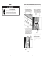
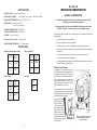
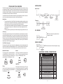
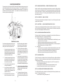
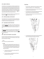
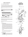
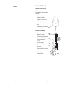
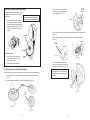
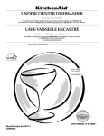
KAD-7
TECHNICAL EDUCATION
Inc.
For the way it's made.™
KUD01
STAINLESS STEEL
DISHWASHER
JOB AID 4317288
48
INTRODUCTION
This Job Aid, KUD01 STAINLESS STEEL DISHWASHERS, Part No. 4317288 provides specific information on the operation, diagnosis and repair of the KitchenAid KUD01 series Stainless Steel Dishwasher.
KUD01 STAINLESS STEEL DISHWASHERS has been compiled to provide the most recent information on design, features, operation, troubleshooting, and repair procedures.
GOALS AND OBJECTIVES
The goal of this Job Aid is to provide detailed information that will enable the service technician to
properly diagnose malfunctions and repair the KUD01 Stainless Steel Dishwasher.
The objectives of the Job Aid are:
The service technician will •
•
•
•
Understand proper safety precautions.
Successfully troubleshoot and diagnose malfunctions.
Successfully perform necessary repairs.
Successfully return the dishwasher to proper operational status.
TO THE INSTRUCTOR/INDEPENDENT STUDENT
This Job Aid is designed to be used with the video tape, KUD01 STAINLESS STEEL DISHWASHERS, Part No. 4317287V.
KITCHENAID CORPORATION ASSUMES NO RESPONSIBILITY
FOR ANY REPAIRS MADE ON OUR PRODUCTS BY ANYONE
OTHER THAN AUTHORIZED SERVICE TECHNICIANS.
© 2000 KitchenAid, Inc., St. Joseph, MI 49013
II
-- NOTES --
TABLE OF CONTENTS
Section One
INSTALLATION CONSIDERATIONS .................................................. 1
GENERAL CONSIDERATION ................................................................. 1
Section Two
THEORY OF OPERATION ................................................................. 3
CONTROL PANELS ................................................................................ 3
CYCLES AND CYCLE VARIATIONS ...................................................... 4
AUTOMATIC PURGE FILTRATION ........................................................ 5
CANCELING A CYCLE ........................................................................... 6
CHANGING A CYCLE ............................................................................. 6
OPTION SELECTIONS ............................................................................ 7
CYCLE STATUS INDICATORS ............................................................... 9
FUNCTION DESCRIPTION ................................................................... 10
Section Three
COMPONENT ACCESS ...................................................................13
COMPONENT LOCATION .................................................................... 13
ACCESSING COMPONENTS IN THE DOOR ....................................... 14
ACCESSING COMPONENTS INSIDE THE TUB .................................. 17
SERVICING THE SUMP ASSEMBLY ................................................... 20
Section Four
TROUBLESHOOTING AND DIAGNOSIS ..........................................25
TROUBLESHOOTING CHART.............................................................. 25
COMMON CYCLE TIME CHART ........................................................... 27
HOW TO USE COMMON CYCLE TIME CHART .................................. 28
COMMON CYCLE TIME CHART NOTES ............................................. 32
RAPID ADVANCE FEATURE & DIAGNOSTIC CYCLES ..................... 36
DIAGNOSTIC CYCLE TIME CHART ..................................................... 37
Section Five
TECH TIPS ....................................................................................39
WIRING DIAGRAM ................................................................................ 39
STRIP CIRCUITS ................................................................................... 40
ELECTRONIC CONTROL CONNECTOR PINS .................................... 41
MODEL/SERIAL NUMBER PLATE ....................................................... 42
MODEL SPECIFIC SERVICE PARTS TABLE ...................................... 43
KEY PAD MATRIX ................................................................................. 43
SPECIFICATIONS ................................................................................. 44
WATER USAGE ..................................................................................... 44
WHAT TO DO IF THE DISHWASHER DOOR DOES NOT OPEN ........ 45
46
III
SAFETY
!
WARNING
ELECTRICAL SHOCK HAZARD
WHAT TO DO IF THE DISHWASHER DOOR DOES NOT OPEN
If the door latch assembly is damaged or malfunctions, the dishwasher door may not open. If this
occurs, the following procedure will open the dishwasher door and allow repairs to the door latch
assembly.
1.
Disconnect power before servicing the dishwasher.
Replace all panels before operating the dishwasher.
Insert an Allen wrench between the
countertop and the top of the console in
the vicinity of the door latch. (Fig. 5-1)
3.
Countertop
Allen Wrench
Failure to do so can result in death or electrical shock.
Open the door. The unsnapped latch
strike will remain attached to the door
catch and will be pulled out of the mount
ing slots in the support collar. (Fig. 5-3)
Cabinet Seal
Removed
Top
of
Console
Console
Fig. 5-1
2.
Turn the Allen wrench down and press
down on the latch strike retainer brackets
to release them from the support collar.
The latch strike retainer brackets are
snapped into the metal ridge on which
the cabinet seal is installed. (Fig. 5-2)
Press Here
Mounting
Slots
Fig. 5-3
Top
of
Console
Press Here
Cabinet
Seal
Support
Collar
Fig. 5-2
IV
45
4.
Remove the latch strike from the door latch
assembly.
5.
Repair the door latch assembly.
6.
Reinsert the latch strike into the slots in
the support collar and snap it into place.
(Fig. 3)
SECTION ONE
INSTALLATION CONSIDERATIONS
SPECIFICATIONS
ELECTRICAL SUPPLY: (Under Load) 60Hz, 120VAC
SUPPLY WATER FLOW RATE:
GENERAL CONSIDERATIONS
(To Fill 2 Quarts (1.9 L) in 27 secs.) - 120psi Max., 20psi MIN.
For complete installation procedures see the “Installation Instructions” in the
literature packet provided with the dishwasher.
SUPPLY WATER TEMPERATURE: 120° F to 160° F (49° C to 71° C)
WATER CHARGE:
1.8 Gal. (6.8 L) / First Fill
1.7 Gal. (6.5 L) / All Other Fills
A video presentation, Key Features and Installation Considerations, part number
4317280V, is available. This video covers the entire installation process.
LOWER SPRAY ARM ROTATION: 25 TO 40 RPM
UPPER SPRAY ARM ROTATION: 25 TO 35 RPM
Each location will present a different set of challenges that can be anticipated and solved before
installation begins.
APF DRAIN: .1 Gal. (.38 L) per 5 sec.
•
Check the planned location of the dishwasher.
•
Easy access to hot water, drain line and electricity.
•
Convenient access for loading. The dishwasher door should open and close freely.
•
The opening under the counter should be square and the cabinet fronts should be perpendicular to the floor.
Water
Usage
(gal/L)
•
Make sure the cabinet opening is free of intrusions such as braces or utility lines.
•
Do not install the dishwasher on carpeted floors.
•
An outside wall behind the dishwasher should be insulated to prevent the water line, inlet valve
and drain line from freezing and rupturing.
APF Pressure Switch Trip Point: 10 In. Water Column
HEATING ELEMENT HEATING RATE: 1°+ F Rise per Minute
WATER USAGE
Baked On Cookware Heavy, Normal
Soil Level
Sensed
China - Light/China
Water
Usage
(gal/L)
Soil Level
Sensed
High
8.8 -10.4/
33.4 -39.4
High
7.1-8.6/
26.9-32.5
Low
6.9/
26.2
Low
5.5/
20.8
Rinse Only
Quick Clean Up
First Fill
Water
Temp
Less
than
135° F
(57° C)
Greater
than
135° F
(57° C)
Water
Usage
Water
Usage
(gal/L)
6.9-8.4/
26.1-31.8
1.8-2.1/
6.9-7.9
5.2-6.7/
19.7-25.4
Additional Considerations
The application of a horizontal pump and filter
technology allows for the tub to be designed three
inches deeper than current models. This deeper
tub and longer door design will impact the installation process because there is less working
space available underneath the unit and correct
routing and placement of the drain hose, water
supply and electrical wiring is critical.
The tub must be level. Reduced water consumption of this dishwasher requires that it be installed
level and plumb for proper water recirculation back
into the sump area during operation.
Do not remove the drain
tube from the left side of
the tub. If the loop is
removed, the dishwasher
will not initiate Automatic
Purge Filtration. The drain
tube also contains a check
valve in the L-connector that
prevents backflow of water into
the dishwasher from the household drain system.
44
Drain Tube
Loop
Main Wash Motor
Drain Pump
Motor
View of Sump Assembly from Underneath
Showing Horizontal Wash Pump Motor
and Drain Pump Motor
1
-- NOTES --
MODEL SPECIFIC TABLES
MODEL
NO.
USER
INTERFACE
KUDS01DJ
8269200 (Top)
8269201 (Front)
KUDS01IJ
8269199
KUDR01TJ
8269198
KUDM01TJ
8269197
KUDI01TJ
8269196
MODEL
NO.
PRESSURE
SWITCH
JUMPER
TAILS
INTERCONNECT
CARD
8269202
8269207
N/A
N/A
DISPENSER
N/A
RINSE
AID
SENSOR
RINSE
AID
HARNESS
8269189
8269190
WIRING
HARNESS
8268477
8269191
8269996
N/A
N/A
KEYPAD MATRIX
2
8269206
8268422
KUDS01DJ
KUDS01IJ
KUDR01TJ
KUDM01TJ
KUDI01TJ
PUMP &
NUMERIC
MOTOR
DISPLAY ASSMEBLY
43
N/A
MODEL/SERIAL NUMBER PLATE
SERIAL NUMBER DESIGNATOR
SERIAL NUMBER
F K
MANUFACTURING SITE
F = Findlay, OH
YEAR OF MANUFACTURE
K = 2000
WEEK OF MANUFACTURE
PRODUCT SEQUENCE NUMBER
36 50001
SECTION TWO
THEORY OF OPERATION
Model/Serial
Number Plate
(Left side of
frame behind
door)
CONTROL PANELS
MODEL KUDI01TJ - 6” Console
MODEL KUDM01TJ - 6” Console
MODEL NUMBER
MODEL NUMBER DESIGNATOR
K UD S
01
T
J
WH
0
INTERNATIONAL SALES OR
MARKETING CHANNEL
K = KITCHENAID BRAND
PRODUCT IDENTIFIER
PD = Convertable/Potable
MODEL KUDR01TJ - 4” Console
UD = Undercounter
FEATURE LEVEL: I, J, M, P, R, S
SERIES CONFIGURATION
FEATURES
YEAR OF INTRODUCTION
J = 2000
COLOR CODE
WH = White
AL = Almond
GR = Graphite
BL = Black
BT = Biscuit
MODEL KUDS01IJ - 4” Console
ENGINEERING CHANGE
0 = Basic Release; 1 = First Revision; 2 = Second Revision
MODEL KUDS01DJ - 4” Split Console
TOP
FRONT
42
3
CYCLES AND CYCLE VARIATION
The KUD01 dishwasher optimizes washing performance and efficiently uses resources by varying
cycle functions and length. The selection of wash options allows the consumer to customize a cycle
for optimum washing performance. The soil sensor monitors soils in the wash water and sends input
to the electronic control. Generally, if the consumer does not choose a wash option, the electronic
control determines which cycle variation should be used.
WATER HEATING
Heater Circuit
In models without the soil sensor feature the electronic control automatically uses the Low Soil variation of the cycle unless the customer has chosen the High Temp Scrub option.
* Resistance and
Wattage
Varies with Temperature
Wash Options
•
•
•
The consumer’s selection of a High Temp Scrub wash option mandates a preset long version
of a wash cycle. The exception is the Normal cycle. If very little soils are present the electronic
control will use the Low Soil cycle variation with the High Temp Scrub option.
The Sani Rinse option will mandate a higher final rinse temperature. This does not lengthen a
cycle except for the time spent in the thermal hold to raise the water temperature to the required 160° F.
The Energy Saver Dry option merely turns off the heat during the drying function of the cycle.
Thermistor
SOIL SENSING
Soil Sensing
The Soil Sensor (pressure switch) monitors soil concentrations during wash functions and communicates this to the electronic control. If one or more soil sensor trips occur in the first washing interval
(interval “42”) of the Pre-Wash Period, the electronic control will use the High Soil version of the cycle.
If there are no trips and no options selected, the control uses the light soil version starting at interval
41. Soil sensor trips also invoke Automatic Purge Filtration (APF) events during the Pre-Wash and
Wash Periods. See APF description on page 5.
First Fill Water Temperature
NOTE: Switch closes when significant soils accumulate in the pump.
RINSE AID SENSING
The duration of the Quick Cleanup cycle may be modified based upon the water temperature of the
first fill. If the thermistor senses water temperature of 135°F or higher, the electronic control will eliminate the second wash function. The Quick Cleanup cycle is the only cycle in which this occurs.
Baked On Cookware
Normal
The most aggressive to virtually eliminate bacteria from the dish load. Use this cycle for hard-toclean, heavily soiled pots, pans, casseroles and
regular tableware. Initial display time: 99 min.
Use this cycle for loads with normal amounts of
food soil. (The energy-usage label is based on
this cycle.) Initial display time: 95 min.
Light/China
Heavy
Use this cycle for china and crystal. This cycle
uses a light wash and gentle dry. During heated
dry, the heating element cycles on and off. Initial
display time: 79 min.
Use this cycle for hard-to-clean, heavily soiled
pots, pans, casseroles and regular tableware.
Initial display time: 97 min.
NOTE: Switch closes when the Rinse Aid dispenser is empty.
ELECTRONIC CONTROL CONNECTOR PINS
PIN
NO.
P1
P2-1
P2-2
P2-3
P2-4
P2-5
P2-6
P3
P4
P5
P6
P7
P8
P9
P10
P12
4
DESCRIPTION
RIBBON CABLE TO USER INTERFACE
PRESSURE SWITCH (SOIL SENSE)
THERMISTOR
FILL VALVE
DISPENSER
OPEN
TO CONTROL POWER SUPPLY
DRAIN MOTOR
WASH MOTOR AUX WINDING
WASH MOTOR RUN WINDING
SWITCHED L1 TO HEATER
AC NEUTRAL
SWITCHED L1 FROM TCO
SWITCHED L1 TO WASH MOTOR COMMON
SWITCHED L1 TO VENT, FILL VALVE,
DISPENSER & PRESSURE SWITCH
OPTIONAL RINSE AID
41
WIRE
COLOR
O-GY
Y-BK
BR
LBU
O-BK
T
GY
Y
BU
W-R
W-V
T
R-BK
BU-BK
R
Quick Clean Up
STRIP CIRCUITS
Use this cycle for pre-rinsed or lightly-soiled loads. The cycle automatically adds a fill and brief prewash, purging cold water from the hot water line improves washing results, without adding time for
water heating periods. Initial display time: 48 min.
FILL
Rinse Only
WASH/RINSE
Use this rinse cycle for rinsing dishes, glasses and silverware that will not be washed right away.
Initial display time: 10 min.
DRAIN
AUTOMATIC PURGE FILTRATION (APF)
The soil sensor (pressure switch) monitors water pressure at the output of the drain pump. The
pressure is created by the concentration of soils trapped against the accumulator screen. As pressure
builds, the water level in the drain tube loop is pushed higher. When the water level in the tube rises
10 inches (the equivalent of 10 inches of water column pressure) the soil sensor switch closes indicating to the electronic control that high soil levels are present.
The electronic control invokes the APF feature in specific intervals of the Pre-Wash and Wash periods. Up to five intervals are available to enable APF events. As many as three APF events may occur
in any one of these intervals, however, APF events will be spaced no less than one minute apart.
DISPENSER
APF operates for a total of 10 seconds while the wash motor continues to operate. The accumulator
screen will be cleaned from jets on the underside of the lower spray arm as the washing action continues.
During the first five seconds, the drain motor turns on and the fill valve is activated. This purges the
soiled water from the accumulator and begins to add fresh water. For the remaining five seconds, the
drain pump is turned off, but the fill valve remains activated to bring the wash water back to the proper
level.
VENT
HEAT DRY
* Resistance and
Wattage
Varies with Temperature
40
5
CANCELING A CYCLE
SECTION FIVE
TECH TIPS
Anytime during a cycle press:
WIRING DIAGRAM
The display shows:
2
The dishwasher starts a two minute drain (if needed.) The wash pump does not operate during this
drain function. Let the dishwasher drain completely. The display turns off after two minutes.
NOTE: If the dishwasher does not need to be drained, the display turns off.
PTC HEATER
To Stop the Drain
Press Cancel/Drain a second time to stop the drain immediately. Always drain the dishwasher before
starting a new cycle.
To Clear the Indicators
Press Cancel/Drain before starting the dishwasher to clear all options and cycles.
CHANGING A CYCLE
During the first fill of a cycle:
1.
Press a new cycle and/or options.
2.
Check the detergent dispensers. They must be filled properly for the new cycle.
After the first fill of a cycle:
1.
Press:
The display shows:
2
The dishwasher starts a two minute drain (if needed.) Let the dishwasher drain completely. The
display turns off after two minutes.
NOTE: If the dishwasher does not need to be drained, the display turns off.
NOTE: Check Strip Circuits for resistance and wattage values.
6
39
-- NOTES --
2.
Check the detergent dispensers. They must be filled properly for the new cycle.
3.
Close the door.
4.
Press a new cycle and/or options.
5.
Press Start.
OPTION SELECTIONS
Hi Temp Scrub
Select this option to increase the target water temperature during the wash portion of
the cycle. Hi Temp Scrub raises this target water temperature to 145° F (63° C)
in the Main Wash for all cycles. In the Baked On Cookware and Heavy cycles, Hi Temp
Scrub also raises the target water temperature to 135° F (57° C) in the pre-wash.
Heating the water helps improve washing results. Hi Temp Scrub is useful when
loads contain baked-on food.
This option adds heat and wash time by adding at least one additional rinse mode to the cycle.
NOTE: Hi Temp Scrub is an option with Baked On Cookware, Heavy and Normal Wash.
Sani Rinse
Select this option to raise the water temperature in the final rinse to approximately
160° F (70° C) for 10 minutes. Sani rinse adds heat and time to the cycle. In the
Normal cycle, this high temperature rinse sanitizes the dishes and glassware in accordance with the NSF International requirements (#95/480/05/2480).
NOTE: The Baked On Cookware cycle automatically uses this option. Sani Rinse is an option with
Heavy and Normal Wash.
Energy Saver Dry
Select this energy-saving option to dry without heat. Air drying is useful when loads
contain plastic dinnerware that may be sensitive to high temperatures. The dishes
take longer to dry and spotting can occur. For best drying, use a liquid rinse aid. Some
items, such as plastics, may need towel drying.
NOTE: Energy Saver Dry is an option with all cycles, except Quick Rinse.
Control Lock
Use the Control Lock to prevent the dishwasher from accidentally being turned on.
Use the Lock, also, to prevent accidental cycle or option changes during a cycle. When
the Lock On Icon is lit, all buttons are disabled.
NOTES:
•
•
The dishwasher door can be opened while the controls are locked.
The lock can be turned on while the dishwasher is running.
To Turn on the Control Lock:
Press and hold the Air Dry button for four (4) seconds. CONTROL LOCK will glow.
38
7
Diagnostic Cycle Time Chart
Delay Hours
Select this option to run the dishwasher at a later time or during off-peak hours. Items can be added
any time during the delay countdown. After adding hours, close the door firmly until it latches. The
delay countdown will not continue if the door is not latched.
Start can be delayed up to 12 or 24 hours depending on the model.
The first time Delay Hours is pressed, the display will show:
18
RINSE AID EMPTY
LOCKOUT
until the desired hours of delay are in the display.
4.
2
1
0
Press Start.
NOTE: To cancel the delay hours cycle press Cancel/Drain. To cancel the delay and start the cycle
immediately, press Start again.
NOTE 1
CYCLE PROG/STATUS LED’s
W1
W2
WASHING (W3)
R1
CIRC (R2) [a.k.a. ‘WASHING’ on some models]
RINSING
DRYING
SOAKING
SOAKING/SENSING
ADD-A-DISH
WATER HEATING
SANI COMPLETE
CLEAN
S
T
A
N
D
B
Y
NOTE 2
INTERVAL TIME (min:sec)
DIAG. CYCLE (Soil Sensor Pres. Sw. Closed)
NOTE 3
DIAG. CYCLE (Soil Sensor Pres. Sw. Open)
NOTE 3
NUMERIC DISPLAY (DISPLAYS INTERVAL NUMBER)
OUTPUT LOADS
VENT
WASH MOTOR MAIN
DRAIN MOTOR
FILL VALVE
UNDEFINED EXTRA OUTPUT
DET-R/A DISPENSER
HEATER
8
1:00
1:00
Repeatedly press:
3
1:00
3.
4
0:02
Select a wash cycle and options.
5
0:05
2.
6
0:05
0:02
0:05
0:10
0:02
To Delay the Start:
Close the door.
8 7
OPTION LED’s
P.SCOUR / H.T.SCRUB
SOAK OPTION
NO HEAT DRY / AIR DRY/ E.SVR.DRY
SANI RINSE
DELAY - 2 HR
DELAY - 4 HR
DELAY - 8 HR
Showing a one (1) hour delay.
1.
9
S
T
A
N
D
B
Y
0:03
•
•
88 10
INTERVAL
CYCLE LED’s
ANTI-BACTERIA / COOKWARE
POTS & PANS / HEAVY
NORMAL
CHINA
QUICK CLEANUP / TIME SAVER
RINSE ONLY
CANCEL DRAIN
>
88 10 9
8
7
6
5
4
3
2
1
0
S
T
A
N
D
B
Y
37
NOTE
3
RAPID ADVANCE SERVICE FEATURE AND DIAGNOSTICS
CYCLES
Pressing the following option keys in the sequence shown will either start the Diagnostics Cycle or turn
on the Rapid Advance feature for stepping through customer selectable cycles:
HIGH TEMP SCRUB, ENERGY SAVER DRY, HIGH TEMP SCRUB, ENERGY SAVER DRY
Or
SANI RINSE, ENERGY SAVER DRY, SANI RINSE, ENERGY SAVER DRY
CYCLE STATUS INDICATORS
The progress of the dishwashing cycle can be followed with the Cycle Status Indicators.
Add Rinse Aid
When the RINSE AID EMPTY indicator is lit, the dispenser is empty and needs to be filled. The light
will glow when a cycle is selected or while a cycle is running.
Sensing/Soak
(Note: HIGH TEMP SCRUB = POWER SCOUR = HIGH TEMP SCOUR)
(Note: AIR DRY = NO HEAT DRY = ENERGY SAVER DRY)
On models equipped with a soil sensing pressure switch, the dishwasher senses the soil level on the
dishes. Soil level determines the length of some cycles, the amount of heat added to the wash or rinse
and the cycle variation needed for the load. Wash action continues while sensing occurs.
If the above key sequence is entered after starting a cycle, the Rapid Advance feature is turned on,
which allows the operator to manually advance the currently running cycle, interval by interval, by
pressing the Pots & Pans/Heavy or Anti-Bacteria/Baked On Cookware or Start key.
Soak helps loosen soils on the dishes, but wash action pauses during soak. The sensing indicator
glows during the soil sensing and soak parts of the cycle. .
If the above key sequence is entered with the dishwasher in Standby, the Diagnostics Cycle is started.
The Diagnostics Cycle can be rapid-advanced, interval by interval, by pressing the Pots & Pans/
Heavy or Anti-Bacteria/Baked On Cookware or Start key.
NOTE: The door must be closed before the Diagnostics cycle will run. Likewise, the door must be
closed after each rapid advance selection of the Pots & Pans/Heavy or Anti-Bacterial/Baked On Cookware key for the control to advance to the next interval of the Diagnostics or currently running cycle.
DIAGNOSTICS CYCLE TIME CHART NOTES
(DIAGNOSTICS CYCLE) NOTE 1 – R/A SENSOR ASSEMBLY CHECK
To help detect a malfuntioning or disconnected Rinse Aid level sensor, the Rinse Aid Empty LED
should light up in Diagnostics if the Rinse Aid dispenser is empty or the circuit is shorted. If the Rinse
Aid Dispenser is full, the LED indicator will not light up during the diagnostic test, except in the first
increment.
Sanitized
If the Sani Rinse option is selected, the sanitized indicator glows when the Sani Rinse cycle is finished.
If the dishwasher did not properly sanitize the dishes, the light flashes at the end of the cycle. This can
happen if the cycle is interrupted. The light goes off when the door in opened.
Clean
The Clean indicator glows when a cycle is finished. The light turns off when the door is opened or
Cancel/Drain is pressed.
Add A Dish
After a cycle starts, additional items can be added to the wash load while ADD A DISH indicator glows.
After the indicator light turns off, items added to the dishwasher may not be completely cleaned.
Water Heating
(DIAGNOSTICS CYCLE) NOTE 2 – THERMISTOR OPEN/SHORT DETECTION
Water Heating indicator glows and the cycle progression pauses whenever water is heated to a set
temperature during a cycle. Wash or rinse action continues as the water heats.
The Diagnostics Test cycle will illuminate the ‘CLEAN’ LED in intervals 10 through 1 whenever it
detects a “short circuit” or “open circuit” in the themistor circuit.
Wash
NOTE: Warm water must be in the dishwasher when performing this test. Otherwise, the control may
falsely determine that the thermistor circuit is “open”.
(DIAGNOSTICS CYCLE) NOTE 3 – STUCK PRESSURE SWITCH DETECTION
The Diagnostics cycle monitors the (normally open) soil-sensing pressure switch input for a “stuck
closed” condition. If a “stuck closed” condition exists, the diagnostic cycle will abort wash interval 3
and skip immediately to drain interval 1.
The Wash indicator glows whenever the dishwasher is performing a wash function.
Rinse
The Rinse indicator glows whenever the dishwasher is performing a rinse function.
Dry
The Dry indicator will glow whenever the dishwasher is performing a heated dry function.
Control Lock
The Control Lock indicator glows whenever the Control Lock feature is on. When the Control Lock
indicator is lit, all buttons are disabled.
36
9
FUNCTION DESCRIPTION
The washing action of the KitchenAid KUD01 Stainless Steel Dishwasher performs more work and
maintains higher performance with reduced energy consumption. This is accomplished with the following: 1) A redesigned wash system using separate wash and drain pumps. 2) A soil sensor and
thermistor which monitor washing conditions. 3) An electronic control board which adjusts cycle
functions to optimize washing performance.
7
NOTE 9 - SOAKING PAUSE INTERVAL — ENERGY STAR NORMAL CYCLE ONLY
Intervals 13 and 32 are mid-cycle soaking/pause intervals and are only used in the Energy Star light
soil/non-sensor version of the Normal cycle. The control stops washing and turns all loads off except
the vent in these intervals. The intent is to let the existing energy in the wash water on the dishes
soften and loosen the food soil. The Soaking and Soaking/Sensing indicators are turned on during
these intervals (see note 7).
NOTE 10 – PULSED DRY — CHINA CYCLE ONLY
8
9
5a
6
The China cycle (on all models) turns the heater off in intervals 1, 3, and 5 of the dry period to create
a gentler “pulsed” dry function.
NOTE 11 – HEATER ON — QUICK CLEANUP/TIME SAVER CYCLE ONLY
To make up for no water heating thermal holds, the heater is turned on in intervals 10-12, 14, and 4142 of the Quick Clean Up/Time Saver cycle. The heater in interval 10 of the Quick Clean Up/Time
Saver cycle is thermally capped at 150F/66C (see note 4).
1a
6
1b
NOTE 14 – POWER SCOUR/HIGH TEMP SCRUB OPTION
1c
3
2 5b
4
9
Wash/Rinse Function
The main wash water passes from the spray arm
nozzles, over the dish load and into the sump assembly, where a number of operations occur.
1.
(5a) The remaining water is allowed to
rejoin the main wash flow by passing
through the separation screen. (5b)
6.
Water and soils pass through the course
protection grate at the top of the sump assembly (1a) and then passes through the
foreign object protector (1b) into the main
wash pump inlet chamber (1c).
7.
2.
The water then passes through the chopper assembly where food particles are reduced in size so they can pass through
the water delivery system. (2)
3.
Water is drawn through the impeller and
into the pump chamber. (3)
4.
5.
8.
Here, 20 percent of the water is diverted
towards the soil accumulator. Food soils
in this water stream are separated by the
separation screen. (4)
9.
Downstream restrictions limit the water
flow into the accumulator to 10 percent.
10
This heavily soiled water is distributed
throughout the accumulator. (6) Soils will
remain trapped in the accumulator until a
drain or Automatic Purge Filtration event
takes place.
Since the water in the accumulator is under some minimal pressure, it rejoins the
main wash water by flowing through the
accumulator screen into the tub. (7) For
this to occur properly it is critical that
the dishwasher be installed perfectly level.
Jets located on the underside of the lower
spray arm continuously wash down the accumulator screen to allow more soils to
concentrate. (8)
The remaining 80 percent of the wash
water will flow from the impeller through
the volute and up through the spray arms.
(9)
The Power Scour/High Temp Scrub option is not allowed with China, Quick Clean Up/Time Saver, or
Rinse Only/Quick Rinse cycles. This option does the following:
(a)
Anti-Bacteria/Cookware and Pots & Pans/Heavy cycles
• Forces the control to run no less than a 5-fill (Wash-Wash-Rinse-Rinse-Rinse-Dry) version
of the cycle, even if no soil is sensed.
• Raises the pre-wash water heating thermal hold (interval 40) to 135F/57C
• Raises the main wash water heating thermal hold (interval 33) to 145F/63C (except AntiBacteria/Cookware cycle, which is already 145F/63C).
(b)
Normal cycles
• Forces the control to run no less than a 4-fill (Wash-Wash-Rinse-Rinse-Dry) version of the
cycle even if no soil is sensed. Note: the standard (non-Energy Star) Normal cycle is al
ready a minimum of 4-fills (Wash-Wash-Rinse-Rinse-Dry) with light/no soil.
• Raises the main wash water heating thermal hold (interval 33) to 145F/63C.
NOTE 15 – SANI RINSE OPTION
The Sani Rinse option is not allowed on China, Quick Clean Up/Time Saver, and Rinse Only/Quick
Rinse cycles. It is “built in” and treated as an automatic option on the Anti-bacteria/Cookware cycles.
This option does the following:
•
Raises final rinse water heating thermal hold (interval 15) to 160F/71C and adds 20 minutes to its default maximum time limit.
•
Turns the heater off in the last two intervals of the dry period (intervals 1 and 2).
•
Invokes the Sanitized status indicator at the end of the cycle (see note 8).
NOTE 16 – AIR DRY/NO HEAT DRY/ENERGY SAVER DRY OPTION
The Air Dry/No Heat Dry option is not allowed on the Rinse Only/Quick Rinse cycle (which has no dry
function). This option does the following:
•
Turns the heater off in the dry period (intervals 1-6).
35
NOTE 5 - NUMERIC CYCLE TIME DISPLAY
Drain Function
Some models with numeric cycle time displays show an animated spinning clock pattern during the
first four intervals of the cycle (intervals 45-42) while sensor based cycle modifications (and true time
remaining) are being determined. Other models simply display the worst case cycle time remaining
(in minutes) until the end of interval 42. See the Model Specifics Table to identify models with numeric
displays and which models exhibit the animated clock pattern. At the end of interval 42, all models
with numeric displays will begin displaying a corrected cycle time (in minutes). From here on, the
display counts down normally, minute by minute, through the rest of the cycle.
Note: Cycle time does not include time spent in thermal holds; the time on the display at the start of
the thermal hold is frozen until the end of the thermal hold (see notes 3 & 6).
1.
During the Drain function, a separate drain pump motor (1) is started while the main wash
pump motor continues to operate for 1 minute. This accomplishes three goals.
2.
First, the jets on the underside of the lower spray arm continue to flush soils from the accumulator screen while the water is drained from the unit. (2)
3.
Second, negative pressure in the main wash pump inlet chamber keeps the check valve closed,
allowing the drain pump to remove soiled water from the accumulator. (3)
4.
Third, the spray arms will rinse down the interior of the wash tub while the water is drained,
leaving the inside free of soils. (4)
NOTE 6 – WATER HEATING (THERMAL HOLD) STATUS INDICATOR
2
The Water Heating indicator is turned on during all thermal hold intervals to signal that cycle timing,
display sequencing, and numeric cycle time display countdown operations have been suspended or
frozen while the water is heated to the proper temperature (see note 3).
2
4
NOTE 7 – SOAKING/SENSING & SOAKING STATUS INDICATORS
In general, the Soaking/Sensing indicator is primarily a “sensing” indicator and is turned on during
cycles whenever the control is still making decisions based on sensor inputs. Specifically this includes
all APF intervals, all thermal hold intervals, and the first four intervals of each cycle (see notes 1, 2,
and 3).
1
The Soaking/Sensing indicator also turns on during “soaking” events like the “soaking/pause” intervals
in the Energy Star low soil/non-sensor version of the Normal cycle (see note 9). A dedicated Soaking
indicator is available for non-numeric models that will likewise turn on during these “soaking” events
but not during “sensing” intervals.
3
NOTE 8 – ‘END-OF-CYCLE’ STATUS INDICATORS – CLEAN and SANITIZED
5.
Both end-of-cycle indicators (Clean and Sanitized) turn on at the end of a cycle and turn off upon
pressing any key or opening and closing the door (note: the indicators stay on as the door is opened
but turn off as soon as the door is closed again).
The main wash pump then stops, creating positive pressure in the pump’s inlet chamber. This
opens the check valve allowing the remaining water to be drained away. (5)
(a) Clean
Comes on at the end of every cycle except Rinse Only/Quick Rinse.
(b)
Sanitized
Comes on at the end of all cycles completed with the Sani Rinse option selected (see note 15).
If the Sani Rinse option is completed successfully, the indicator is turned on steady at the end
of the cycle. If the Sani Rinse was unsuccessful (see below), the indicator will flash ½ second
on, ½ second off, repeatedly, at the end of the cycle. The Sani Rinse will be deemed unsuccessful (& flash the indicator) if:
(1)
The thermal hold in the final rinse (interval 15) fails to reach the required 160F/71C
before timing out on its default time limit.
(2)
The door is opened and/or power is interrupted between the end of the final rinse
thermal hold (interval 15) and the end of the cycle.
34
5
11
Automatic Purge Filtration
NOTE 2 – APF ENABLED INTERVALS
The Automatic Purge Filtration feature may be invoked if the soil sensor detects excessive soils. This
can occur during selected wash or rinse functions. APF mode provides one or more purges of excess
soils trapped in the soil accumulator at specified intervals in a cycle.
The APF (Automatic Purge Filtration) wash system allows the control to continuously filter and flush
food soil out of the pump during “APF enabled” intervals scattered throughout each cycle and do it
without interrupting the cycle. The control monitors the pressure switch (soil sensor) input during each
of the APF enabled intervals in the cycle (see time chart). Whenever a pressure switch trip is detected
in one of these APF intervals, the control executes a 10-second “APF purge” to clear the pump of
soils. These APF purges occur in parallel with the cycle and do not interrupt or affect the timing of
other functions (like washing) in the interval. Each APF purge consists of 5 seconds of Fill and Drain
followed immediately by 5 seconds of Fill by itself. If an APF purge is executed during a heated wash
interval, the heater must be turned off during the first 5-second Fill and Drain portion of each purge,
but cycle timing is not affected and the heater turns back on midway through the purge.
1.
The APF mode operates for a total of 10 seconds while the wash pump continues to wash.
The accumulator screen will be cleaned from jets on the underside of the lower spray arm. (1)
2.
During the first five seconds, the drain pump (2) turns on and the fill valve is activated. This
purges the soiled water from the accumulator and begins to add fresh water.
1
1
2
Multiple APF purges can occur within each APF interval of the cycle but are limited by certain frequency and quantity limits:
•
APF purges must be spaced at least 60 seconds apart within any given APF interval (the
pressure switch will be ignored prior to 60 seconds).
•
The maximum number of APF purges allowed within a given APF interval is specified on the
time chart in that interval (the pressure switch will be ignored for the duration of an APF
interval once the maximum APF limit for that interval has been exceeded). In interval 33, the
limit is “1” for 120F thermal holds and “3” for all other thermal hold setpoint temperatures.
Note: Models without pressure switches (soil sensors) never get sensor trips and thus never execute
APF purges. (See Model Specifics Table to identify models without pressure switches).
NOTE 3 – WATER HEATING THERMAL HOLD INTERVALS
APF Function
First Five Seconds
3.
For the remaining five seconds, the drain pump is turned off, (3a) but the fill valve remains
activated to bring wash water back to the proper level. (3b)
3b
During water heating thermal holds (intervals 40, 33, & 15), cycle timing is interrupted and the dishwasher continues washing while it heats the water to the setpoint temperatures specified on the time
chart for each version of the cycle. The Water Heating and Sensing indicators are turned on and the
cycle time displayed by models with numeric displays is frozen during thermal hold intervals (see
notes 5, 6, & 7). The dishwasher will hold in this suspended, water heating mode until the water
reaches the temperature specified for the thermal hold or a maximum default time limit for the thermal
hold (below) expires. At the conclusion of the thermal hold, the control resumes normal operation and
timing and proceeds to the next interval.
The default maximum time limits for all the thermal hold intervals are as follows (in minutes):
3a
Anti-bacteria/Cookware
Pots & Pans/Heavy
Normal
China
Pre-Wash
30
30
—
—
Main Wash Final Rinse
35
50
35
30
45
40
45
30
(Final Rinse with Sani Rinse)
(50)
(50)
(60)
(—)
(Quick Clean Up/Time Saver and Quick Rinse/Rinse Only cycles have no thermal hold intervals)
NOTE 4 – THERMALLY CAPPED INTERVALS
APF Function
Last Five Seconds
Interval 34 is a heated wash interval thermally capped at 150F/66C. Interval 10 is only heated for the
Quick Clean Up/Time Saver cycle and is thermally capped in that situation at 150F/66C. Anytime the
thermal cap temperature is exceeded during one of these intervals, the heater will turn off, but the
dishwasher will continue washing for the duration of the interval.
12
33
COMMON CYCLE TIME CHART NOTES
SECTION THREE
COMPONENT ACCESS
NOTE 1 – CYCLE MODIFICATIONS BASED ON SENSOR INPUTS
COMPONENT LOCATION
The control monitors food soil and temperature sensors during the first four intervals of the cycle
(intervals 45-42) to determine what sensor based cycle modifications are appropriate. The modifications made to the cycle depend on the cycle and options selected as well as the sensor inputs. Note
the interval skip arrows and thermal hold temperature changes on the time chart for each version of
the cycle.
In addition to being able to modify the cycle itself based on soil sensor input, the APF (Automatic
Purge Filtration) wash system allows the control to continuously filter and flush food soil out of the
pump during “APF enabled” intervals scattered throughout each cycle and do it without interrupting
the cycle (see note 2 on APF).
(a)
Anti-Bacteria/Cookware, Pots & Pans/Heavy, Normal, and China Cycles
The control assumes that the worst case cycle (the high soil version) is going to be required
until the true soil level is determined. The soil level is determined by counting the number of
pressure switch (soil sensor) trips that occur in the first APF interval of the cycle (interval 42).
If no trips are detected in interval 42, the control modifies the remainder of the cycle to match
the light soil/non-sensor version of the cycle. If one or more trips are detected in interval 42,
the control continues with the heavy soil version of the cycle.
Upper
Spray
Arm
Active
Vent
Control
Panel
Inner Feed Tube
Electronic
Control Board
(Interconnect
Board Underneath)
Middle Spray
Arm
Door Latch Assembly
Dispenser
Assembly
Sump and Motor
Assembly
Note: Energy Star models have a different light soil/non-sensor version of the Normal cycle than
other models (see Model Specifics table to identify Energy Star models).
Note: Models without pressure switches (soil sensors) never get sensor trips and thus always default
to the light/non-sensor version of the cycle and never execute APF purges. (See Model Specific
Tables to identify models without pressure switches).
Note: The Power Scour/High Temp Scrub option can override or alter the soil-based cycle modifications (see note 14).
(b)
Time Saver/Quick CleanUp Cycles
The control does NOT modify the Quick CleanUp/Time Saver cycle based on soil level. Instead, it modifies the cycle based on incoming water temperature detected during the first fill
interval of the cycle (interval 45). The control assumes the worst case cycle (Cool First Fill
version) will be required until the end of interval 42. At the end of interval 42, it modifies the
remainder of the cycle based on the inlet water temperature it actually detected in the first fill.
If the water was more than 135° F/57° C it changes to the “Hot First Fill” version of the cycle. If
the water was less than 135° F, it will continue with the “Cool First Fill” version of the cycle. The
“Cool First Fill” version of the cycle basically contains an extra drain and fill prior to the main
wash to increase the initial water temperature for the main wash and reduce the time needed
to heat the water.
Water Inlet
Float
Lower Spray
Arm
Drain Tube
Heating
Element
Accumulator
Check Valve
(in drain tube)
Soil Sensor
Pressure Switch
Drain Pump Motor
Wash Pump
Like other cycles, the Quick CleanUp/Time Saver cycle does allow APF purges to occur (in
APF intervals) if pressure switch trips occur, but cycle timing is not modified.
(c)
Rinse Only/Quick Rinse Cycles
The control does NOT modify the Rinse Only/Quick Rinse cycle based on sensor inputs. Like
other cycles, it does allow APF purges to occur (in APF intervals) if pressure switch trips occur
but the Rinse Only/Quick Rinse cycle timing itself is not modified based on any sensor inputs.
32
Thermistor
Run Capacitor
Wash Pump Motor
13
Cycle Progression & Status Indicators-Output Loads
!
IMPORTANT
Electrostatic Discharge (ESD) Sensitive Electronics
ESD problems are present everywhere. ESD may damage or weaken the electronic control assembly. The new control assembly may appear to work well after repair is finished, but failure may
occur at a later date due to ESD stress.
• Use an anti-static wrist strap. Connect wrist strap to green ground connection point or unpainted metal in the appliance. - OR - Touch your finger repeatedly to a green ground connection point or unpainted metal in the appliance.
• Before removing the part from its package, touch the anti-static bag to a green ground connection point or unpainted metal in the appliance.
• Avoid touching electronic parts or terminal contacts; handle electronic control assembly by
edges only.
• When repacking failed electronic control assembly in anti-static bag, observe above instructions.
!
WARNING
ELECTRICAL SHOCK HAZARD
Located in the lower third section of the left column are a listing of cycle Status Indicators (1) signifying
what is happening during a cycle. Some of these indicators are for engineering use only and not
applicable for service diagnosis (†). The output loads (2) are listed at the bottom of the left hand
column. The solid and shaded bars to the right indicate the potential use of cycle indicators and loads
by at least one cycle variation. (Fig. 4-4)
(1)
17
Failure to do so can result in death or electrical shock.
ACCESSING COMPONENTS IN THE DOOR
15
14
SOAKING
SOAKING/SENSING
ADD-A-DISH
WATER HEATING (THERMAL HOLD INDICATOR)
SANITIZED
CLEAN
OUTPUT LOADS
WASH MOTOR (MAIN WINDING)
DRAIN MOTOR
FILL
APF ENABLED INTERVALS -Max # of APF Purges allowed in Interval
DETERGENT / RINSE AID DISPENSER
VENT
HEATER
(2)
Fig. 4-4
Rinsing Indicator should be lit
3
15
4
11
11
Wash Motor should be running
Using the Common Cycle Time Chart
To confirm the correct operation of a cycle or properly diagnose a malfunction, the following information must be determined:
The control panel on the KitchenAid KUD01 Dishwasher comes in two versions: a) Split Controls: Top
and Front Display and b) Front Display. Both control panels are removed in the same manner.
•
What Cycle Option was chosen?
14
9
11
† NOTE: These cycle progressions are not used
for service diagnosis.
What cycle was chosen?
— If Quick Cleanup cycle was chosen, what was the first fill water temperature?
Fig. 3-1
9
NOTES 4,10,11,16
•
The control panel will now drop down and be free of the door assembly. The wiring harness
will remain connected to the console components.
10
NOTE 2
NOTE 2
NOTE 2
Removing the Console Panel
2.
11
NOTE 6
NOTE 8,15
NOTE 8
Does the model have a Soil Sensor?
Remove the six (6) screws securing the control panel to the door frame. (Fig. 3-1)
12
NOTE 7
NOTE 7
•
1.
13
RINSING
DRYING
Disconnect power before servicing the dishwasher.
Replace all panels before operating the dishwasher.
16
“CYCLE PROGRESSION & STATUS INDICATORS
†PROG BAR W1
†PROG BAR W2
WASHING (PROG BAR W3)
†PROG BAR R1
†CIRC (PROG BAR R2) (This LED will be labeled as ‘WASHING’ on models that use it, but it is on during all Wash and Rinse Periods)
Proceed with the following steps:
1.
Start the selected cycle and program the unit for Rapid Advance service feature. (See page
36).
NOTE: Most likely the cycle that is selected will change to the “Low Soil” variation because of
low soil levels. Also, APF events will not occur. to check the APF function, the harness leads
to the soil sensor will need to be shorted together. Shoring these lwads tells the electronic
control that “High Soil” levels are present.
2.
Advance through the intervals to the one that will operate the load or perform the function to be
checked.
3.
If the load does not operate, refer to the wiring diagram or applicable strip circuit to determine
what connections and components to check. (See Section Five - TECH TIPS.)
4.
Whenever possible, check components for resistance or continuity. On components where
resistance or continuity checks are not reliable, conduct voltage checks.
31
8
0:05
0:05
41
40
THERMAL HOLD
[99] [98] [98] [98] 94
[99] [98] [98] [98] 94
[99] [98] [98] [98] 86
[135F / 57C]
92
[135F / 57C]
92
[135F / 57C]
84
39
38
1:00
Length of
Interval
42
1:00
43
2:00
44
4:00
45
Time
Remaining
in
Display
Thermal Hold intervals do not show specific time
lengths. The length of these intervals is determined by input from the thermistor. (Fig. 4-3) If
the thermal cap temperature is not reached in a
predetermined length of time, the electronic control will proceed to the next interval. (See Note 3,
page 33.)
92
91
92
91
84
83
Bracketed number indicate Spinning
Clock until cycle variation is
determined.
Removing the Electronic Control Board
The electronic control board on the KitchenAid KUD01 Dishwasher is virtually the same configuration
for both the split controls and the full control versions.
ALL MODELS
1.
Disconnect the ribbon connector and the wiring harness connectors from the electronic control
board.
2.
Use a flat bladed screwdriver to depress the
holding tabs at the left end of the control board
assembly while pulling up. (Fig. 3-2, Inset)
Fig. 4-2
Cycle Minutes
Remaining
When Thermal Hold
is Initiated
41
40
THERMAL HOLD
[99] [98] [98] [98] 94
[99] [98 [98] [98] 94
Fig. 4-3
>
[99] [98 [98] [98] 86
[135F / 57C]
92
[135F / 57C]
92
[135F / 57C]
84
39
38
1:00
0:05
42
2:00
43
4:00
44
1:00
Intervals
Always Used
45
0:05
Thermal Hold
Intervals do not have
specified time length
1:35
In the same row as the Cycle Name, the shaded
or solid bars indicate all possible intervals that
may be used in that cycle. All clear intervals are
never used. In cycle variation intervals, black bars
indicate intervals always used. Gray bars with
arrows indicate intervals that are skipped in one
or more variations of a cycle. Shaded bars without arrows indicate that the heater may or may
not be invoked during thermal holds. (NOTE:
During APF and drain functions the heater is
turned off. This is a UL requirement and is built
into the electronic control programming. See Note
2, page 33)
Intervals
1:35
There are 45 intervals in the Common Cycle Time
Chart. Not all intervals have the same time assignments from cycle to cycle. An interval may
be only seconds long or up to 20 minutes in length.
More than one function can take place during an
interval. The LED display, if present, will show
the time remaining in the cycle. (Fig. 4-2)
92
91
92
91
84
83
Inset
Depress tabs
with Screwdriver
SPLIT CONTROL MODELS
3.
Once the Electronic Control Board is removed, a ribbon cable interconnect board
is exposed. (Fig. 3-3)
4.
Unsnap the interconnect board from the
control panel assembly.
5.
Disconnect the three ribbon cables from
the interconnect board.
Fig. 3-2
Interconnect
Control Board
Intervals that
are skipped
Thermal Cap
Temperature
Quick Clean/Time Saver Cycle
Holding
Tabs
The Quick Clean/Timer Saver cycle has a unique variation. During the initial water fill, the thermistor
in the sump monitors the incoming water temperature. If it is 135° F (57° C) or above the electronic
control will skip intervals 39 through 36. This shortens the wash/rinse time by eliminating a drain and
fill sequence (See Note 1b and 1c, page 32).
Fig. 3-3
Removing the Door Latch Assembly
The Door Latch Assembly for both the Split Control and Full Control versions are essentially the
same assembly. The latch handle is installed in
one of two positions and the door microswitch will
be located on either the right or left of the assembly depending on the control panel version. Removal of the entire door latch assembly is the
same for both versions.
1.
30
Fig. 3-4
Inset
Release the tabs securing the door latch
assembly to the control panel and lift the
assembly out. (Fig. 3-4, Inset)
Tab
15
Removing the Door Latch Microswitch
HOW TO USE THE COMMON CYCLE TIME CHART
The Microswitch will be located on either the right or left side of the door latch assembly depending on
the control panel version.
1.
Disconnect the wiring harness connectors from the microswitch terminals.
2.
Pull back on the two (2) plastic retaining tabs securing the microswitch to the door latch
assembly and lift the microswitch out. (Fig. 3-5)
Inset
The Common Cycle Time Chart reproduced on page 27 of this Job Aid can be found on the Tech
Sheet supplied with each dishwasher. The Tech Sheet is located behind the access panel at the
bottom of the unit.
The Common Cycle Time Chart appears to be more complex than a typical Esterline Chart. This is a
result of the greatly expanded number of cycles and cycle variations possible with electronic controls
as opposed to previous electro-mechanical controls. The chart reflects all possible cycles/cycle variations available on ALL Year 2000 Stainless Steel Dishwasher models. As a result the chart may list
some cycles that will not apply to the specific model being serviced.
Lift Microswitch
Common Cycle Time Chart Layout
The wash cycles are listed on the left side of the chart. Cycle names such as Anti-Bacterial/BakedOn-Cookware may be designated as Anti-Bacterial on some models and Baked-On-Cookware on
others. Cycle variations are listed directly underneath each cycle name. These variations are dependent on one or more of the following factors:
Spread Tabs
(Caution: These
tabs can break.)
Removing the Active Vent
Assembly
1.
2.
3.
4.
5.
What, if any, wash options were chosen?
•
The Soil Sensor detected soil in the water. (NOTE: If the Soil Sensor does not trip during a
particular cycle, the unit uses the same variation of the cycle that is applicable for nonsensor models.)
In Figure 4-1, gray highlighted cycle variations indicate options the customer can select (Notes 1 & 3,
pages 32 & 33). The gray highlighted cycle variation Low Soil - ENERGY STAR is an exception and
indicates a unique default cycle for these models (Note 1a, page 32). The unhighlighted cycle variations are based on input from the soil sensor or are defaults based on specific models (Notes 2 & 4,
page 33).
Fig. 3-5
Use Flat Bladed
Screwdriver and Turn
interior Vent Grille ¼ Turn
Counter-clockwise
The Active Vent Assembly is located in the console area.
•
Cycle
Name
Note 1
Note 3
Note 4
Note 5
Disconnect the wiring harness connectors
from the wax motor terminals on the active vent assembly.
NOTES 1A,9,14B,15,16
INTERVAL TIME (min:sec)
Note 2
Remove the six (6) screws securing the
control panel to the door frame.
NORMAL
HIGH SOIL WITH P.SCOUR / H.T.SCRUB OPTION [Soil sensed in Interval 42]
NOTE 14B
NUMERIC DISPLAY CYCLE TIME (spinning “CLOCK” pattern in INTERVALS 45-42 for some models, see NOTE 5)
HIGH SOIL [Soil sensed in Interval 42]
NOTE 1A
NUMERIC DISPLAY CYCLE TIME (spinning “CLOCK” pattern in INTERVALS 45-42 for some models, see NOTE 5)
LOW SOIL (or Non-Sensor Model) H.T.SCRUB OPTION [No soil sensed in Interval 42]
NOTE 14B
NUMERIC DISPLAY CYCLE TIME (spinning “CLOCK” pattern in INTERVALS 45-42 for some models, see NOTE 5)
LOW SOIL (or Non-Sensor Model) [No soil sensed in Interval 42]
NOTE 1A
NUMERIC DISPLAY CYCLE TIME (spinning “CLOCK” pattern in INTERVALS 45-42 for some models, see NOTE 5)
LOW SOIL (or Non-Sensor Model) [No soil sensed in Interval 42] — E. STAR MODEL
NOTE 1A
NUMERIC DISPLAY CYCLE TIME (spinning “CLOCK” pattern in INTERVALS 45-42 for some models, see NOTE 5)
95:00 w/o Th.Holds
95:00 w/o Th.Holds
87:25 w/o Th.Holds
87:25 w/o Th.Holds
78:20 w/o Th.Holds
Fig. 4-1
Note 1 - Customer Selected Option, High Soils Sensed
Loosen, but do not remove the four T-15
Torx screws securing the left side of the
outer door panel to the door frame. This
will provide addition room to easily remove
the active vent assembly.
Notes further
explain
Cycle/Variation
Function
Note 2 - No Option Selected, High Soils Sensed
Note 3 - Customer Selected Option, Cycle Adjusted/
Shortened because no soils were sensed. (This
variation only applies to the normal cycle.) Cycle
variation may be same as Non-Sensor models.
Using a flat bladed screwdriver in the slot
provided at the bottom of the interior vent
grille, turn the vent grille counterclockwise
¼ turn and remove the grille. (Fig. 3-6)
Fig. 3-6
Note 4 - No Option Selected, Cycle Adjusted/Shortened
because no soils were sensed. Cycle variation may be
same as Non-Sensor models.
During Soil Sensing function (Interval 42), the LED
display will show spinning “CLOCK” pattern. Clock
countdown will begin once the cycle variation has
been determined.
Note 5 - No Option Selected, Cycle Adjusted/Shortened
because no soils were sensed. Cycle variation is
unique to Energy Star models.
The active vent assembly will drop free of
the dishwasher door.
16
Cycle Duration
NOT
Including
Thermal Holds
29
-- NOTES --
Removing the Dispenser Assembly
The Dispenser Assembly is located in the lower portion of the dishwasher door below the console
area.
1.
Remove the eight (8) screws securing the outer door panel to the dishwasher door frame.
(Fig. 3-7) Remove the outer door panel from the door frame.
2.
Remove the center top hex head screw and remove the dispenser shield and disconnect the
wiring harness connectors from the detergent dispenser solenoid and rinse aid sensor.
(Fig. 3-8)
3.
Remove the remaining five (5) screws securing the dispenser assembly to the inner door liner.
(Fig. 3-8)
4.
Bend the two locking tabs at the top and bottom of the dispenser assembly up away from the
dispenser body.
5.
The dispenser assembly can now be lifted from the inner door liner.
Dispenser
Shield
Tab
Tab
Remove This
Screw First
Fig. 3-7
Fig. 3-8
SERVICING COMPONENTS INSIDE THE TUB
Removing the Inner Feed Tube and Lower Spray Arm
The Inner Feed Tube is held in place by two (2) metal clips. (Fig. 3-9) One is located on the inner top
of the dishwasher tub. The second is located on the back of the dishwasher tub. (Fig. 3-10, Inset)
Inset
Fig. 3-9
28
1.
Remove the two (2) dishracks from the
dishwasher tub.
2.
Unsnap the inner feed tube from the two
(2) metal clips securing it to the dishwasher tub.
Clip
Fig. 3-10
17
3.
Rotate the rear feed cap (Fig. 3-11a) ¼ turn clockwise (Fig. 3-11b)
Rear Feed Cap
Fig. 3-11b
Fig. 3-11a
4.
The entire inner water tube assembly and the lower spray arm assembly can now be removed
from the dishwasher tub.
Removing the Water Inlet
The water inlet is located on the left side of the dishwasher tub. (Fig. 3-12)
1.
From the inside of the tub, use a small pair of Channel Locks™ and turn the inlet grille ¼
turn counterclockwise and remove the grille. (Fig. 3-13)
2.
The water inlet can now be separated from the dishwasher tub.
Water Inlet Grille
Water Inlet
THIS IS THE FOLDOUT PAGE FOR THE
COMMON CYCLE TIME CHART
11 X 17
Water Inlet
Fig. 3-12
Fig. 3-13
Servicing the Heating Element
The heating element (Fig. 3-14) should not be removed unless it has failed. All critical components
of the dishwasher can be removed without removing the heating element.
Heating Element
Fig. 3-14
If the heating element must be removed, it must
be replaced with a new one.
When installing a new heating element, follow the
Installation Instructions provided with the new item.
18
27
-- NOTES --
Servicing the Overfill Assembly
Removing the Overfill Control Switch
The overfill control switch can be removed from
the overfill assembly without removing the assembly from the tub.
1.
Remove the toe and access panels from
the bottom of the dishwasher.
2.
Unsnap the cover over the overfill control switch.
3.
Lift the overfill control switch from the assembly.
4.
Disconnect the wiring harness connectors
from the switch terminals.
Float
Removing the Overfill Assembly
1.
Remove the toe and access panels from
the bottom of the dishwasher.
2.
Tip the float slightly and gently toward the
back of the tub and lift up to disengage it
from the overfill assembly body.
(Fig. 3-15)
3.
Remove the standpipe nut.
4.
Push the overfill assembly through the
bottom of the tub.
5.
Open the cover and lift the overfill control
switch from the assembly.
6.
Disconnect the wiring harness connectors
from the switch terminals.
Standpipe
Nut
Tip Float Slightly
Toward Back to
Disengage It from
the Overfill
Assembly Body
Overfill
Switch
Cover
Overfill
Control
Switch
Overfill
Assembly
Fig. 3-15
26
19
SERVICING THE SUMP ASSEMBLY
Removing the Sump Assembly
SECTION FOUR
The entire sump assembly can be removed from inside the dishwasher tub.
1.
Remove the access and toe panels from
underneath the dishwasher door by removing the two (2) screws securing it to
the dishwasher frame. (Fig. 3-16)
TROUBLESHOOTING CHART
PROBLEM
Dishwasher does not run
or stops during a cycle
2.
Disconnect the wiring harness connectors
from the drain pump motor terminals, the
soil sensor and the thermistor.
3.
Disconnect the drain tube from the soil sensor
(if present) on the drain pump outlet.
4.
Remove the soil sensor, if present.
(See procedure below.)
6.
Remove the three (3) sump tabs that
secure the sump assembly to the dishwasher tub. (Fig. 3-17, Inset)
1. Door is not latching properly.
3. Wash Cycle not set properly.
Fig. 3-16
Remove the drain pump motor. (See
procedure below.)
POSSIBLE CAUSES
2. Child lock is "ON".
Toe Panel
5.
7.
TROUBLESHOOTING AND DIAGNOSIS
Access Panel
Inset
4. Household fuse blown or circuit
breaker tripped.
Locator Key
5. Dishwasher is not wired into a
circuit with proper voltage.
Sump
Tab
From inside the tub, lift the back of the
sump up approximately ½ inch.
Push the assembly back, lift up the front
and then lift it out.
Sump Tab
NOTE: When reinstalling the sump assembly,
align the locator key with the corresponding
slot in the tub opening. (Fig. 3-17)
Dishwasher will not fill
1. Overflow protection float is
stuck in "up" position.
2. Fill valve is inoperable.
Sump
Tab
3. Control board is inoperable.
Fig. 3-17
Dishwasher will not drain
Removing the Soil Sensor
1. Air gap (if installed) is clogged.
2. Pump motor is inoperable
If so equipped, a soil sensing pressure switch is mounted on the drain pump outlet. Disconnect the two
wiring harness connectors from the switch terminals. Disconnect the drain tube. (Fig. 3-18A) Remove the Torx T-15 screw securing sensor assembly to the pump base. Lift it from the pump outlet.
(Fig. 3-18B)
Soil Sensor
Pressure Switch
Fig. 3-18B
Drain Pump
Fig. 3-18A
Removing the Drain Pump Motor
1.
With one hand, press back on the plastic tab that holds
the pump motor from rotating. (Fig. 3-19)
2.
With the other hand, rotate the pump motor counterclockwise approximately ¼ turn. The pump motor will now be
free of the pump assembly.
20
3. Control board is inoperable.
Dishwasher will not
dry dishes
CORRECTION/TEST
1. Check to make sure handle
is properly seated in door
latch assembly. Check that
the door switch is opening
and closing properly.
2. Turn child lock "OFF". See Use
and Care Guide.
3. Review setting Wash Cycles
in the Use and Care Guide.
4. Have a qualified electrician
check the circuit breaker or
fuse.
5. Have customer call a qualified
electrician.
1. Check that the overflow protection float is free to move
"up" and "down" Check that
the overfill switch in opening
and closing properly.
2. Check for continuity between
contacts on fill valve.
3. Check for 120VAC between
P8 and P2-3.
1. Follow air gap manufacturer's
directions for cleaning.
2. Disconnect pump motor from
wiring harness and check for
continuity between GY & BU/
BK.
3. Check for 120VAC between
P8 and P3.
1. Heater element is open or shorted. 1. • Check for continuity between the terminals of the
heater element.
• Check for 120VAC between
P8 and Neutral.
2. Hi-limit thermostat inoperable.
2. Check for continuity between
terminals of the hi-limit
thermostat.
3. Active vent wax motor inoperable. 3. • Check for continuity between terminals of the
wax motor.
• Check for 120VAC between
P8 and Neutral.
Fig. 3-19
25
-- NOTES -Removing the Wash Motor
1.
Remove the bolt securing the wash
motor and drip shield in place on the pump
assembly. (Fig. 3-20)
2.
Once the bolt and drip shield are removed,
turn the wash motor counter-clockwise
until it stops (approximately ¼ turn).
3.
Inset
Pull the motor straight back from the sump
assembly. Some effort may be necessary
to dislodge the motor. The volute will remain attached to the motor. (See Figure
3-24, page 22)
Drip Shield
NOTE: When reinstalling the wash motor and
volute, do not pinch the volute seal between the
volute and sump. Use a small amount of rinse
aid on the volute seal to help installation. (Fig. 324, page 22)
4.
Fig. 3-20
With the wash motor removed, the separation
screen can be removed from the sump base.
(Fig. 3-21)
Separation Screen
Chopper Screen
Fig. 3-21
5.
The thermistor can be removed from the sump
by turning it ¼ turn counterclockwise and
pulling it out. (Fig. 3-22) The thermistor can
be removed without removing the sump
assembly from the tub. NOTE: Make sure
water is completely drained from sump.
Access to the thermistor can be gained by
removing the access and toe panels while
the unit is in its installed position.
24
21
Thermistor
Fig. 3-22
Bolt Holds Drip
Shield in Place
3.
Removing the Impeller from the Wash Motor
The impeller is attached to the wash motor and can
be removed once the wash motor is removed from
the pump base.
1.
Place the end of a flat-bladed screwdriver
into the back of the wash motor to hold the
armature of the motor from turning while unscrewing the impeller clockwise. (Fig. 3-23)
Take care not to scratch or nick the motor
windings.
Foreign
Object
Protector
Remove the screw securing the foreign
object protector to the sump base and
remove the protector. (Fig. 3-27)
Do not touch seal surfaces on the
impeller or the volute. Contamination
or damage will cause premature failure.
Fig. 3-27
4.
Remove the screw securing the inlet protector to the sump base and lift the inlet protector out.
(Fig. 3-28)
5.
Remove the chopper assembly from the impeller shaft and lift it from the sump base.
(Fig. 3-29)
Seal Surface
Chopper
Inlet
Protector
Fig. 3-23
Volute
To Remove the Volute
1.
2.
Align the arrow on the volute and the
locator triangle on the wash motor
frame as in Figure 3-24.
Fig. 3-28
Volute
Seal
Fig. 3-29
Fig. 3-24
6.
Lift the volute from the wash motor.
Accessing Components in the Sump Assembly
Components inside the sump can be accessed without removing the sump from the dishwasher tub.
1.
Remove the four (4) Torx T-20 screws securing the soil accumulator from the sump base.
(Fig. 3-25)
2.
The soil accumulator assembly will now lift free of the sump base. (Fig. 3-26)
The check valve, located between the
wash motor and the drain can be removed
with a pair of needle nose pliers. (Fig. 3-30)
NOTE: When replacing the check valve,
simply drop it in place. The inlet protector
will seat the flapper valve properly when it is
reinstalled.
Accumulator
Check
Valve
Fig. 3-30
Sump
Base
Fig. 3-25
Fig. 3-26
22
23