1
s
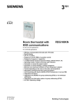
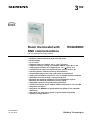
Room thermostat with
KNX communications
3
192
RDG400KN
For VAV heating and cooling systems
KNX bus communications (S-mode and LTE mode)
Backlit display
PI / P control
Output for VAV box / damper: DC 0…10 V / 3-position
Output for heating / cooling coil: ON/OFF, PWM or 3-pos / DC 0..10V
Output signal inversion as an option (DC 0...10 V DC 10...0 V)
2 multifunctional inputs for keycard contact, external sensor, etc
Operating modes: Comfort, Economy and Protection
Control depending on the room or the return air temperature
Supply fan optimization: Input DC 0...10 V for damper position feedback
Automatic or manual heating / cooling changeover
Minimum and maximum limitation of room temperature setpoint
Minimum and maximum limitation of air flow signal
Adjustable commissioning and control parameters
Commissioning with Synco ACS700, ETS3 Professional or via local HMI
Integration into Synco
Integration into DESIGO via group addressing (ETS3) or via individual
addressing
Integration into third-party system via group addressing (ETS3)
Operating voltage AC 24 V
CE1N3192en
01 Jun 2010
Building Technologies
Use
The RDG400KN room thermostat is designed for the following types of system:
VAV systems via ON/OFF or modulating control outputs:
Single-duct system
Single-duct system with electric heater
Single-duct system and radiator / floor heating
Single-duct system with heating / cooling coil
The room thermostat is delivered with a fixed set of applications.
The relevant application is selected and activated during commissioning using one
of the following tools:
Synco ACS
ETS3 Professional (planned)
Local DIP switch and HMI
Functions
Room temperature control via built-in temperature sensor or external room
temperature / return air temperature sensor
Changeover between heating and cooling mode (automatic via local sensor or
bus, or manual)
Selection of applications via DIP switches or commissioning tool (ACS700,
ETS3 Professional)
Select operating mode via operating mode button on the thermostat
Temporary Comfort mode extension
Display of current room temperature or setpoint in °C and/or °F
Minimum and maximum limitation of room temperature setpoint
Minimum and maximum limitation of air flow signal
Button lock (automatic or manual)
2 multifunctional inputs, freely selectable for:
Operating mode switchover contact (keycard, window contact, etc.)
Changeover sensor for automatic heating / cooling mode
External room temperature or return air temperature sensor
Dewpoint sensor
Electric heater enable
Faults
Monitor input for temperature sensor or switch status
One DC 0...10 V input for damper position feedback
Floor heating temperature limit
Reload factory settings for commissioning and control parameters
KNX bus (terminals CE+ and CE-) for communication with Synco or KNX
compatible devices
Display of outside temperature or time of day via KNX bus
Time scheduling and central control of setpoints via KNX bus
A RMB7xx / RMU7xx controller (signal exchange over KNX) uses:
the air demand signal of the thermostat to optimize supply air temperature.
the energy demand signals of the heating / cooling device to optimize energy
supply.
the damper position feedback (DC 0...10 V) to optimize supply fan speed.
2 / 14
Siemens
Building Technologies
RDG400KN Room thermostat with KNX communications
CE1N3192en
01 Jun 2010
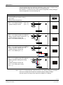
Applications
The thermostat supports the following applications, which can be configured using
the DIP switches at the rear of the unit or a commissioning tool.
DIP switches 1...3 need to be set to OFF (remote configuration, factory setting) to
select an application via commissioning tool.
Application
DIP switches
Remote configuration
via commissioning tool (factory setting)
Synco ACS
ETS3 professional (planned)
Single-duct
DC 0…10 V damper actuator
(P47 = 0)
3-position damper actuator
(P47 = 1)
ON
OFF
2
3
4
5
1
2
3
4
5
1
2
3
4
5
1
2
3
4
5
1
2
3
4
5
3192S07
1
T
B1
YV
V
ON
M
Single-duct and radiator / floor heating
DC 0…10 V damper actuator and ON/OFF,
PWM or 3-position radiator (P47 = 0)
3-position damper actuator and
DC 0…10 V radiator (P47 = 1)
T
B1
YV
V
ON
M
OFF
YE
3192S09
Single-duct with electric heater
DC 0…10 V damper actuator and ON/OFF,
PWM or 3-position electric heater (P47 = 0)
3-position damper actuator and
DC 0…10 V electric heater (P47 = 1)
3192S08
OFF
T
B1
YV
V
ON
M
OFF
Single-duct heating and cooling coil
DC 0…10 V damper actuator and ON/OFF,
PWM or 3-position heating and cooling
(P47 = 0)
3-position damper actuator and
DC 0…10 V heating and cooling
(P47 = 1)
Note
3192S11
YR
T
(B1)
YV
V
M
Y1
ON
OFF
T
(B1)
Use P47 to change damper output from DC 0...10 V (factory setting) to 3-position
Use P46 to change valve output from ON/OFF (factory setting) to PWM
Use DIP switch 5 to change valve output from ON/OFF to 3-position
3 / 14
Siemens
Building Technologies
RDG400KN Room thermostat with KNX communications
CE1N3192en
01 Jun 2010
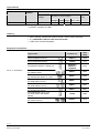
Type summary
Product no.
Stock
number
Features
Operating
voltage
ON/OFF PWM
RDG400KN
S55770-T165
AC 24 V
Backlit
LCD
Number of control outputs
1
1)
1
1)
3-pos DC 0…10 V
1 1)
1
1) ON/OFF, 3-position or PWM
Ordering
When ordering, indicate both product number / stock number and name:
E.g. RDG400KN / S55770-T165 room thermostat
Order valve actuators separately.
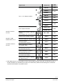
Equipment combinations
Product no.
Data
sheet
Cable temperature sensor
QAH11.1
1840
Room temperature sensor
QAA32
1747
QXA2000 /
QXA2001 /
AQX2000
1542
SSA61...
4893
SSC61…
4895
SSP61…
4864
SSB61...
4891
SSD61...
4861
STS61
4880
SQS65…
4573
Type of unit
Condensation detector / Supply unit
DC 0..10 V actuators
Electrical actuator, DC 0..10 V
(for radiator valve)
Electrical actuator, DC 0..10 V
(for 2 and 3 port valves / V…P45)
Electrical actuator, DC 0..10 V
(for small valve 2,5 mm)
Electrical actuator, DC 0..10 V
(for small valves 5.5 mm)
Electrical actuator, DC 0..10 V
(for Combi-valve VPI45)
Thermal actuator, DC 0..10 V
(for small valves and radiator
valves)
Electromotoric actuator, DC 0..10V
(for valves 5.5 mm)
4 / 14
Siemens
Building Technologies
RDG400KN Room thermostat with KNX communications
CE1N3192en
01 Jun 2010
Type of unit
Product no.
Data
sheet
GQD161…
4605
GDB161…
4634
GLB161…
DC 0…10 V damper actuator
GMA161…
4614
GEB161…
4621
GCA161…
4613
GBB161…
4626
GIB161…
GDB181.1E/3
VAV compact controller
3544
GLB181.1E/3
ON/OFF actuators
AC 24 V
Electromotoric ON/OFF valve and
actuator
MVI…/MXI…
4867
Electromotoric ON/OFF actuator
SFA71...
4863
Thermal actuator (for radiator valve)
STA71...
4877
Thermal actuator
(for small valves 2.5 mm)
STP71...
4878
Electrical actuator, 3-position
(for radiator valve)
SSA81...
4893
Electrical actuator, 3-position
(for small valve 2,5 mm)
SSP81…
4864
Electrical actuator, 3-position
(for small valve 5,5 mm)
SSB81...
4891
Electrical actuator, 3-position
(for Combi-valve VPI45)
SSD81...
4861
Electromotoric actuator, 3-position
(for valves 5.5 mm)
SQS85…
4573
(only available in AP, UAE, SA and IN)
ON/OFF / PWM
actuators AC 24 V *)
3-position actuators
AC 24 V
*) With PWM control, it is not possible to ensure exact parallel running of more than one thermal actuator. If
several actuators are controlled by the same room thermostat, preference should be given to motorized
actuators with ON/OFF or 3-position control.
5 / 14
Siemens
Building Technologies
RDG400KN Room thermostat with KNX communications
CE1N3192en
01 Jun 2010
Accessories
Description
Changeover mounting kit (50 pcs / package)
Adapter plate 120 x 120 mm for 4“ x 4“
conduit boxes
Adapter plate 112 x 130 mm for surface wiring
KNX Power supply 160 mA (Siemens BT LV)
KNX Power supply 320 mA (Siemens BT LV)
KNX Power supply 640 mA (Siemens BT LV)
Product no. /
stock no.
ARG86.3
Data
sheet
N3009
N3009
ARG70
N3009
ARG70.2
5WG1 125-1AB01
-5WG1 125-1AB11
-5WG1 125-1AB21
--
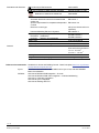
Mechanical design
The room thermostat consists of 2 parts:
Plastic housing with electronics, operating elements and room temperature
sensor
Mounting plate with screw terminals
The housing engages in the mounting plate and is secured with 2 screws.
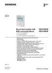
Operation and settings
1
2
1. Operating mode selector / Esc
2. Protection and OK
3. Rotary knob to adjust setpoints
3
and parameters
6 / 14
Siemens
Building Technologies
RDG400KN Room thermostat with KNX communications
CE1N3192en
01 Jun 2010
Display
#
Symbol
Description
# Symbol Description
1
Heating mode
11
Confirmation of parameters
2
Heating mode,
electric heater active
12
Degrees Celsius
Degrees Fahrenheit
3
Cooling mode
13
Digits for room temperature and setpoint display
4
Comfort
14
Button lock active
5
Economy
15
Condensation in room (dewpoint sensor active)
6
Auto Timer mode according to
schedule (via KNX)
16
Weekday 1…7 from KNX bus
1 = Monday / 7 = Sunday
7
Protection mode
17
Fault
8
Escape
18
Temporary timer function; visible when
operating mode is temporarily extended
(extended presence or absence)
9
Additional user information, like outor time of day
door temperature
from KNX bus. Selectable via parameters
19
Indicates that room temperature is displayed
10
Morning: 12-hour format
Afternoon: 12-hour format
20
Primary fan is active (only supported with
Synco700 primary controller)
Engineering notes
See the "Reference documentation", page 12 for information on how to engineer
the KNX bus (topology, bus repeaters, etc.) and how to select and dimension
connecting cables for supply voltage and field devices.
7 / 14
Siemens
Building Technologies
RDG400KN Room thermostat with KNX communications
CE1N3192en
01 Jun 2010
Mounting and installation
Do not mount on a wall in niches or bookshelves, behind curtains, above or near
heat sources, or exposed to direct solar radiation. Mount about 1.5 m above the
floor.
Mounting
Mount the room thermostat on a clean, dry indoor place without direct airflow
from a heating / cooling device, and not exposed to drips or splash water.
Wiring
See the mounting instructions M3192 enclosed with the thermostat.
Comply with local regulations to wire, fuse and earth the thermostat.
The power supply line must have an external fuse or circuit breaker with a rated
current of no more than 10 A.
Isolate the cables of inputs X1-M, U1-G0 and D1-GND for 230 V if the conduit
box carries AC 230 V mains voltage.
Inputs X1-M or D1-GND: Several switches (e.g. summer/winter switch) may be
connected in parallel. Consider overall maximum contact sensing current for
switch rating.
Isolate the cables of KNX communication input CE+ / CE- for 230 V if the conduit
box carries AC 230 V mains voltage.
No cables provided with a metal sheath.
Disconnect from supply before removing from the mounting plate.
Commissioning notes
Applications
The room thermostat is delivered with a fixed set of applications.
Select and activate the relevant application during commissioning using one of the
following tools:
Local DIP switch and HMI
Synco ACS
ETS3 Professional (planned)
Set the DIP switches before snapping the thermostat to the mounting plate, If you
want to select an application via DIP switches,.
All DIP switches need to be set to “OFF” ("remote configuration"), if you want to
select an application via commissioning tool.
8 / 14
Siemens
Building Technologies
RDG400KN Room thermostat with KNX communications
CE1N3192en
01 Jun 2010
After power is applied, the thermostat resets and all LCD segments flash, indicating that the reset was correct. After the reset, which takes about 3 seconds, the
thermostat is ready for commissioning by qualified HVAC staff.
If all DIP switches are OFF, the display reads "NO APPL" to indicate that application commissioning via a tool is required.
Note
Each time the application is changed, the thermostat reloads the factory setting for
all control parameters, except for KNX device and zone addresses!
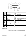
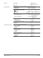
Connect the Synco ACS or ETS3 Professional tools to the KNX bus cable at any
point for commissioning:
Connect tool
KNX
KNX
G
G0
X1
M
U1 D1 GND CE+ CEY10
Y1
Y2
N1
Siemens
N148 /
UP146 /
UP152
Siemens
OCI700
KNX
USB
V24
ETS
3192A04
RS232
ETS / ACS
ACS and ETS3 require an interface:
RS232 KNX interface (e.g. Siemens N148 / UP146 / UP152)
OCI700 USB-KNX interface
Note
An external KNX bus power supply is required if an RDG400KN is connected
directly to a tool (ACS or ETS3) via KNX interface.
Control parameters
The thermostat's control parameters can be set to ensure optimum performance of
the entire system (see basic documentation P3192).
The parameters can be adjusted using
Local HMI
Synco ACS
ETS3 Professional (planned)
Control sequence
The control sequence may need to be set via parameter P01 depending on the
application. The factory setting is “Cooling only”
Calibrate sensor
Recalibrate the temperature sensor if the room temperature displayed on the
thermostat does not match the room temperature measured (after min. 1 hour of
operation). To do this, change parameter P05
Setpoint and setpoint
range limitation
We recommend to review the setpoints and setpoint ranges (parameters
P08…P12) and change them as needed to achieve maximum comfort and save
energy
9 / 14
Siemens
Building Technologies
RDG400KN Room thermostat with KNX communications
CE1N3192en
01 Jun 2010
Programming mode
The programming mode helps identify the thermostat in the KNX network during
commissioning.
Press the left and right buttons simultaneously for 6 sec to activate programming
mode, which is indicated on the display with "PrOg".
Programming mode remains active until the identification of the thermostat is
complete.
Assign KNX group
addresses
Use ETS3 Professional to assign the KNX group addresses of the RDG communication objects,.
KNX serial Number
Each device has a unique KNX serial number inside of the plastic housing.
An additional sticker with the same KNX serial number is enclosed in the packaging box. This sticker is intended for installers for documentation purposes.
Disposal
This device is classified as waste electronic equipment under European Directive
2002/96/EC (WEEE) and may not be disposed of as unsorted municipal waste.
Adhere to all relevant national laws.
Regarding disposal, use the systems setup for collecting electronic waste.
Observe all local and applicable laws.
Technical data
Power supply
Outputs
Inputs
Operating voltage
SELV AC 24 V 20%
Frequency
50/60 Hz
Power consumption
Max. 2 VA / 1 W
DC 0…10 V
Control output Y10-G0
39 mV
Resolution
Max. 1 mA
Current
Control output Y1, Y2-G
AC 24 V
Rating
Max. 1 A
Multifunctional inputs
X1-M
Temperature sensor input
QAH11.1 (NTC)
Type
Digital input
Selectable (NO/NC)
Operating action
DC 0…5 V, max. 5 mA
Contact sensing
U1-G0
Input for actual damper position feedback
damper position 0% (fully closed) DC 0…10 V, max 0.3 mA
0…100%
100% (fully open)
D1-GND
Selectable (NO/NC)
Operating action
SELV DC 6…15 V, 3…6 mA
Contact sensing
Selectable
Function of inputs
X1: P38
External temperature sensor, heating/cooling
D1: P42
changeover sensor, operating mode switchover
contact, dewpoint monitor contact, enable
electric heater contact, fault contact, monitoring
input
10 / 14
Siemens
Building Technologies
RDG400KN Room thermostat with KNX communications
CE1N3192en
01 Jun 2010
KNX bus
Operational data
Interface type
KNX, TP1-64
(electrically isolated)
Bus current
20 mA
Bus topology: See KNX manual (reference documentation, see below)
Switching differential, adjustable
Heating mode
(P30) 2 K (0.5...6 K)
Cooling mode
(P31) 1 K (0.5...6 K)
Setpoint setting and setpoint range
Comfort
Economy
Protection
Multifunctional inputs X1 / D1
Input X1 default value
(P08)
(P11-P12)
(P65-P66)
Input D1 default value
Environmental conditions
21 °C
(5…40 °C)
15 °C/30 °C (OFF, 5…40 °C)
Built-in room temperature sensor
Measuring range
Accuracy at 25 °C
Temperature calibration range
Settings and display resolution
Setpoints
Current temperature value displayed
Operation
Climatic conditions
Temperature
Humidity
Transport
Climatic conditions
Temperature
Humidity
Mechanical conditions
Storage
Climatic conditions
Temperature
Humidity
8 °C/OFF (OFF, 5…40 °C)
Selectable (0...8)
(P38) 1 (Ext. temperature sensor,
room or return air)
(P42) 3 (Operating mode
switchover)
0…49 °C
< ± 0.5 K
± 3.0 K
0.5 °C
0.5 °C
IEC 721-3-3
Class 3K5
0 ...50 °C
< 95% r.h.
IEC 721-3-2
Class 2K3
25... 60 °C
< 95% r.h.
Class 2M2
IEC 721-3-1
Class 1K3
25... 60 °C
< 95% r.h.
11 / 14
Siemens
Building Technologies
RDG400KN Room thermostat with KNX communications
CE1N3192en
01 Jun 2010
Standards and directives
conformity to EMC directive
C-tick conformity to EMC emission standard
Reduction of hazardous substances
Product standards
Automatic electrical controls for household and
similar use
Special requirements for temperature-dependent
controls
Electronic control type
General
Home and Building Electronic Systems
Electromagnetic compatibility
Emissions (residential)
Immunity
(Industry and residential)
Safety class
Pollution class
Degree of protection of housing
Connection terminals
Housing front color
Weight without / with packaging
2004/108/EC
AS/NZS 61000.6.3: 2007
2002/95/EG
EN 60730–1
EN 60730–2-9
2.B (micro-disconnection on
operation)
EN 50090-2-2
IEC/EN 61000-6-3
IEC/EN 61000-6-2
III as per EN 60730
Normal
IP30 as per EN 60529
Solid wires or stranded
wires with wire end sleeves
1 x 0.4…2.5 mm2
or 2 x 0.4…1.5 mm2
RAL 9003 white
0.237 kg / 0.360 kg
Reference documentation Handbook for Home and Building Control - Basic Principles (www.knx.org/uk/newspress/publications/publications/)
Synco
CE1P3127 Communication via the KNX bus for Synco 700, 900 and RXB/RXL
Basic documentation
DESIGO
CM1Y9775 DESIGO RXB integration – S-mode
CM1Y9776 DESIGO RXB / RXL integration – individual addressing
CM1Y9777 Third-party integration
CM1Y9778 Synco integration
CM1Y9779 Working with ETS
12 / 14
Siemens
Building Technologies
RDG400KN Room thermostat with KNX communications
CE1N3192en
01 Jun 2010
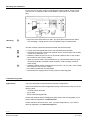
3192A01
Connection terminals
G
X1
G0
M
U1
CE+ CE -
D1 GND
Y1 Y2
Y10
G, G0
Operating voltage AC 24 V
Y10/G0
Control output for DC 0…10 V actuator
Y1/G, Y2/G Control output for 2-position, PWM or 3-position
actuators
X1
Multifunctional input for temperature sensor (e.g.
QAH11.1) or potential-free switch
Factory setting: external temperature sensor
(function can be selected via parameters P38)
M
Measuring neutral for sensors and switches
U1
DC 0…10 V input for actual damper position
(Note: G0 is the measuring neutral for U1!)
D1, GND Multifunctional input for potential-free switch.
Factory setting: Operating mode switchover
contact
(function can be selected via parameters P42)
CE+
KNX data +
CEKNX data –
SELV
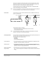
Application
G
KNX
S1
F
10 A
AC 24 V
B1
G
X1
S3
r1
M
U1
G0
D1 GND
Y10
CE+ CEY1
Y2
N1
Single duct
V1
1 mA max.
G0
V1
1 A max.
Single-duct with
electric heater,
radiator or
heating / cooling
valve
V1
V2
1 mA max.
V2
3192A02
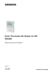
Connection diagrams
N1
V1
Room thermostat RDG400KN
Damper actuator or VAV compact controller:
DC 0…10 V or 3-position
V2 Electric heater, radiator
or heating / cooling valve:
DC 0…10 V, 2-position, PWM or 3-position
S1 Switch (keycard, window contact, etc.)
r1
Feedback signal for actual damper position
S3 Switch at SELV input
(keycard, window contact)
B1 Temperature sensor (return air temperature,
external room temperature, changeover
sensor, etc.)
CE+ KNX data +
CE- KNX data –
1 A max.
V1
1 A max.
13 / 14
Siemens
Building Technologies
RDG400KN Room thermostat with KNX communications
CE1N3192en
01 Jun 2010
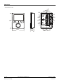
Dimensions
Dimensions in mm
4.0
28.3
28.3
9.0
4.0
128.0
28.3
28.3
28.3
27.7
16.0
93.0
28.5
30.8
14 / 14
2010 Siemens Switzerland Ltd
Siemens
Building Technologies
RDG400KN Room thermostat with KNX communications
28.2 27.8
Subject to change
CE1N3192en
01 Jun 2010