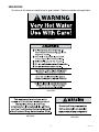
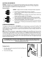
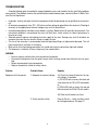
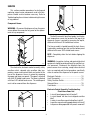
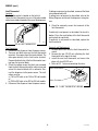
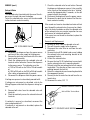
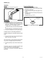
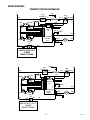
1
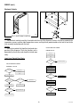
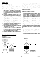
BUNN
®
D
B ISC
E
R FO ON
W
E R N
P
A
LA E EC
R
C RE T
E M F
N
M O R
IN
E V O
N A M
G
T L P
O
F OF OW
A A E
N N R
Y Y S
C P O
O A U
M N R
P E C
O L E
N O
E R
N
T!
H5E
H5X
!
G
IN
RN ter
WAt Wa e!
!
Ho ar
ry h C
Ve Wit
e
Us
OPERATING & SERVICE MANUAL
BUNN-O-MATIC CORPORATION
POST OFFICE BOX 3227
SPRINGFIELD, ILLINOIS 62708-3227
PHONE: (217) 529-6601 FAX: (217) 529-6644
10420.0000G 7/00 © 1989 BUNN-O-MATIC CORPORATION
CONTENTS
Introduction ................................................. 2
Warranty ...................................................... 2
User Notices ................................................ 3
Electrical Requirements ............................... 4
Plumbing Requirements .............................. 4
Initial Set-Up ................................................ 5
Draining the Dispenser ................................ 5
Cleaning ....................................................... 5
Troubleshooting .......................................... 6
Service ......................................................... 9
Wiring Schematics..................................... 20
INTRODUCTION
This equipment heats and dispenses water on demand for beverages and cooking purposes. It has a panel
above the faucet that indicates the status of the dispenser. This equipment is for indoor use, either wall-mounted
or on a sturdy counter or shelf.
WARRANTY
Bunn-O-Matic Corp. (“Bunn”) warrants the equipment manufactured by it to be commercially free from defects
in material and workmanship existing at the time of manufacture and appearing within one year from the date of
installation. In addition:
1.) Bunn warrants electronic circuit and/or control boards to be commercially free from defects in material and
workmanship for two years from the date of installation.
2.) Bunn warrants the compressor on refrigeration equipment to be commercially free from defects in material
and workmanship for two years from the date of installation.
3.) Bunn warrants that the grinding burrs on coffee grinding equipment will grind coffee to meet original factory
screen sieve analysis for three years from date of installation or for 30,000 pounds of coffee, whichever comes first.
This warranty does not apply to any equipment, component or part that was not manufactured by Bunn or that,
in Bunn’s judgement, has been affected by misuse, neglect, alteration, improper installation or operation, improper
maintenance or repair, damage or casualty.
THE FOREGOING WARRANTY IS EXCLUSIVE AND IS IN LIEU OF ANY OTHER WARRANTY, WRITTEN OR
ORAL, EXPRESS OR IMPLIED, INCLUDING, BUT NOT LIMITED TO, ANY IMPLIED WARRANTY OF EITHER
MERCHANTABILITY OR FITNESS FOR A PARTICULAR PURPOSE. The agents, dealers or employees of Bunn are
not authorized to make modifications to this warranty or to make additional warranties that are binding on Bunn.
Accordingly, statements by such individuals, whether oral or written, do not constitute warranties and should not
be relied upon.
The Buyer shall give Bunn prompt notice of any claim to be made under this warranty by telephone at (217)
529-6601 or by writing to Post Office Box 3227, Springfield, Illinois, 62708-3227. If requested by Bunn, the Buyer
shall ship the defective equipment prepaid to an authorized Bunn service location. If Bunn determines, in its sole
discretion, that the equipment does not conform to the warranty, Bunn shall repair the equipment with no charge
for parts during the warranty period and no charge for labor by a Bunn Authorized Service Representative during
the warranty period. If Bunn determines that repair is not feasible, Bunn shall, at its sole option, replace the
equipment or refund the purchase price for the equipment.
THE BUYER’S REMEDY AGAINST BUNN FOR THE BREACH OF ANY OBLIGATION ARISING OUT OF THE SALE
OF THIS EQUIPMENT, WHETHER DERIVED FROM WARRANTY OR OTHERWISE, SHALL BE LIMITED, AS
SPECIFIED HEREIN, TO REPAIR OR, AT BUNN’S SOLE OPTION, REPLACEMENT OR REFUND.
In no event shall Bunn be liable for any other damage or loss, including, but not limited to, lost profits, lost sales,
loss of use of equipment, claims of Buyer’s customers, cost of capital, cost of down time, cost of substitute
equipment, facilities or services, or any other special, incidental or consequential damages.
2
10420 072500
USER NOTICES
The notices on this dispenser should be kept in good condition. Replace unreadable or damaged labels.
12593.0000
00831.0000
00656.0000
10044.0000
3
10420 072500
ELECTRICAL REQUIREMENTS
CAUTION - The dispenser must be disconnected from the power source until specified in Initial Set-Up.
This dispenser requires 2-wire, grounded service rated 120, 208, or 240 volts ac, 20 amp, single phase.
(Refer to the dispenser’s dataplate for exact voltage requirement.)
Electrical Hook-Up
CAUTION – Improper electrical installation will damage electronic components.
WHITE
NEUTRAL
L1 BLACK
120V.A.C.
1.
2.
3.
4.
5.
L2 RED
208 or 240V.A.C.
L1 BLACK
6.
An electrician must provide electrical service as specified.
Using a voltmeter, check the voltage and color coding of each conductor at
the electrical source.
Remove the upper and lower rear panels. Place the tank heater switch on the
electronic control assembly in the “OFF” position.
Install a strain relief and the proper electrical wiring to the terminal block.
Connect the dispenser to the power source and verify the voltage at the terminal block before proceeding. Reinstall both rear panels.
If plumbing is to be hooked-up later be sure the dispenser is disconnected from
the power source. If Plumbing has been hooked-up, the dispenser is ready for
Initial Set-Up.
PLUMBING REQUIREMENTS
This dispenser must be connected to a COLD WATER system with operating pressure between 20 and 90 psi (138
and 620 kPa) from a 1⁄2" or larger supply line. A shut-off valve should be installed in the line before the dispenser.
Install a regulator in the line when pressure is greater than 90 psi (620 kPa) to reduce it to 50 psi (345 kPa). The
water inlet fitting is 1⁄4" flare.
NOTE - Bunn-O-Matic recommends 1⁄4" copper tubing for installations of less than 25 feet and 3⁄8" for more than
25 feet from the 1⁄2" water supply line. At least 18 inches of an FDA approved flexible beverage tubing, such as
reinforced braided polyethylene or silicone, before the dispenser will facilitate movement to clean the countertop.
It can be purchased direct from Bunn-O-Matic (part number 00326-0000). Bunn-O-Matic does not recommend
the use of a saddle valve to install the dispenser. The size and shape of the hole made in the supply line by this type
of device may restrict water flow.
O
N
OFF
This equipment must be installed to comply with the Basic Plumbing Code of the Building Officials
and Code Administrators International, Inc. (BOCA) and the Food Service Sanitation Manual of the
Food and Drug Administration (FDA).
MA O
GE
LIA
Plumbing Hook-Up
CO
mb
us
tr ic
a
RE
ti b l c o
, F MP
le s
IR LY
de
IN AD
E,
.
s.
BIL CL TH
OR RISK
ITY UDIN E E
SH S E
BE G NTIR
OC QU
FO TH
K H IP
RE E L E OP
TH
BU IMIT ER
AZ MEN
IS
YIN O AT
AR T
A
F W ING
CO PP
G
D
OR A
NN LIA
M
NC
US RRA ANU
0083 EC
TE E IS
IN NT AL
1.00
G
D
00A
TO HEA
TH Y AN
5/88
IS
A TE
©
PR D
D
1988 PO
OD
WE WH
BU
NN
UC
EN
-O-M R S
EV
T
O
AT
UR ER
IC
CO
CE
RP
OR
AT
ION
1. Flush the water line and securely attach it to the flare fitting on the
rear of the dispenser.
2. Turn-on the water supply.
co This
mp eq
ly uip
Ad th with me
n
m e
a in Bu the t is
of nd thistra ildin Bas to b
the e tor g O ic e in
Fo Foo s In ffic Plum sta
od d S ter ials b lle
an er nati a ing d to
d D vic on nd Co
rug e S al, Co de
Ad anit Inc. de of
min atio (B
istr n M OCA
ati an )
on ua
(F l
DA
).
4
P1770
10420 072500
INITIAL SET-UP
CAUTION - The dispenser must be disconnected from the power source throughout the initial set-up, except
when specified in the instructions.
3.
4.
5.
6.
DO
!
CA
UT
IO
N
ON
N
O
N
P TICE
Un OT
til W Tu
OFFSTONO
ate rn O
AD
r
RE
Au Hot W Co n Th
tom a
me e T
a te
s F an
Co ticall r Sys
k
ro
m O Hea
Ac ffee y W tem
co
pe ter
rda Bre hen U s –
W
w
Fa nce W ers nit Is ater ned Swit
Fa ch
ilu
–
re ith Th Fill TConn Tank
u
To
e In he ecte Wil cet!
W d lF
C
s
N
2.
Remove the upper rear panel and place the tank heater switch in
the “OFF” position and replace the panel.
Connect the dispenser to the power source and turn-on the water
supply.
Water will automatically flow into the tank to the proper level and
shut-off. This will take approximately 10 minutes.
Disconnect the dispenser from the power source, remove the upper rear panel and place the tank heater switch in the “ON” position, and replace the panel.
Connect the dispenser to the power source and wait approximately
twenty minutes for the water in the tank to heat.
On models with ready indicator, the indicator will glow when the
proper water temperature for use is achieved.
O
1.
om talla ate To ill
ply tion r Ta Pow
In nk er!
Vo
ids struc In
Wa tions
rra !
nty
!
WA
HA
RN
IN
G
ZA
VO RD
LT OU
AG S
DIS
E
C
PO ONN
BE WE ECT
FO R S F
RE O RO
RE URC M
MO E
VIN
G!
P1771
NOTE - Discontinue dispensing if the indicator LED turns off. Dispense only when the indicator LED glows.
DRAINING THE DISPENSER
CAUTION - The dispenser must be disconnected from the power source throughout these steps.
1.
2.
3.
4.
5.
Disconnect the dispenser from the power source.
Shut-off and disconnect the incoming water supply
Remove the 4-40 screws at the sides of the top panel.
Gently remove one of the grommets from the tank lid.
Insert a tube to the bottom of the tank and syphon ALL of the water out. Bunn-O-Matic has a syphon assembly available (#12440.0000) for this purpose.
NOTE - The dispenser must be full using the INITIAL SET-UP steps before reconnecting to the power source.
CLEANING
The use of a damp cloth rinsed in any mild, non-abrasive, liquid detergent is recommended for cleaning all
surfaces on Bunn-O-Matic equipment.
WALL MOUNTED INSTALLATION
If the dispenser is wall mounted, the bottom of the dispenser should be at the same height as a counter or
table top. Use B.O.M. part #12542.0000 for side mounted Wall Bracket Kit or # 13125.0001 for front mounted
Wall Bracket Kit .
SUPPORT FOR LARGE RECEPTACLES
CAUTION: If the dispenser is to be used with larger receptacles such as pitchers or pots, those receptacles must
be adequately supported during dispensing of hot water to avoid spillage of very hot water. This support may be
provided by a table or counter top, or use B.O.M. part #12599.0000 Shelf Kit
5
10420 072500
TROUBLESHOOTING
A troubleshooting guide is provided to suggest probable causes and remedies for the most likely problems
encountered. If the problem remains after exhausting the troubleshooting steps, contact the Bunn-O-Matic Technical Service Department.
•
•
•
•
•
•
•
Inspection, testing, and repair of electrical equipment should be performed only by qualified service personnel.
All electronic components have 120 – 240 volt ac and low voltage dc potential on their terminals. Shorting of
terminals or the application of external voltages may result in board failure.
Intermittent operation of electronic circuit boards is unlikely. Board failure will normally be permanent. If an
intermittent condition is encountered, the cause will likely be a switch contact or a loose connection at a
terminal or crimp.
Solenoid removal requires interrupting the water supply to the valve. Damage may result if solenoids are
energized for more than ten minutes without a supply of water.
The use of two wrenches is recommended whenever plumbing fittings are tightened or loosened. This will
help to avoid twists and kinks in the tubing.
Make certain that all plumbing connections are sealed and electrical connections tight and isolated.
This dispenser is heated at all times. Keep away from combustibles.
WARNING
• Exercise extreme caution when servicing electrical equipment.
• Disconnect the dispenser from the power source when servicing, except when electrical tests are specified.
• Follow recommended service procedures
• Replace all protective shields or safety notices
Problem
Probable Cause
Remedy
Equipment will not operate.
1. No power or incorrect voltage
(A) Check the terminal block for the correct voltage. It should be:
a.) 100 to 120 volts ac across the black and
white terminals for 100 to 120 volt models
or,
b.) 200 to 240 volts ac across the red and
black terminals for 200 to 240 volt models.
(B) Check circuit breakers or fuses.
2. Safety overflow switch
6
Refer to Service – safety overflow switch
for testing procedures. See page 17.
10420 011599
TROUBLESHOOTING (cont.)
Problem
Probable Cause
Remedy
Automatic refill will not operate 1. No water
after drawing hot water.
2. Water strainer/flow control
Check plumbing and shut-off valves.
(A) Direction of flow arrow must be pointing towards dispenser.
(B) Remove the strainer/flow control and
check for obstructions. Clear or replace.
3. Safety overflow switch
Refer to Service – safety overflow switch
for testing procedures. See page 17.
4. Liquid level system
Refer to Service – electronic controls for
testing procedures. See page 10.
5. Solenoid valve
Refer to Service – solenoid valve for testing procedures. See page 18.
Water flows into the tank con- 1. Solenoid valve
tinuously (Dispenser disconnected from power source).
Refer to Service – solenoid valve for testing procedures. See page 18.
Water flows into the tank con- 1. Liquid level system
tinuously (Dispenser connected
to power source).
Refer to Service – electronic controls for
testing procedures. See page 10.
Water is cold.
1. Tank heater switch
Tank heater switch must be in the “ON”
position.
2. Safety overflow switch
Refer to Service – safety overflow switch
for testing procedures. See page 17.
3. Limit thermostat
Refer to Service – limit thermostat for testing procedures. See page 16.
CAUTION – Do not eliminate or bypass limit thermostat. Use only B.O.M. replacement part #23717.0001.
4. Tank heater
Refer to Service – tank heater for testing
procedures. See page 19.
5. Temperature control
Refer to Service – electronic controls for
testing procedures. See page 10.
7
10420 011599
TROUBLESHOOTING (cont.)
Problem
Probable Cause
Remedy
Water boils continuously.
1. Temperature control
Refer to Service – electronic controls for
testing procedures. See page 10.
2. Lime build-up
Inspect the tank assembliy for excess lime
deposits. Delime as required.
CAUTION – Tanks and tank components should be delimed reglarly depending on local water conditions. Excessive mineral build-up on stainless steel surfaces can initiate corrosive reactions resulting in serious leaks.
Dispenser is making unusual 1. Solenoid valve
noises.
The nut on top of the solenoid valve must
be tight or it will vibrate during operation.
2. Plumbing lines
Plumbing lines should not be resting on the
counter top.
3. Water supply
(A) The dispenser must be connected to a
cold water line.
(B) Water pressure to the dispenser must
not be higher than 90 psi (620 kPa). Install
a regulator if necessary to lower the working pressure to approximately 50 psi (345
kPa).
Ready indicator will not light. 1. Temperature control
(when temperature is within 4°
of its selected setting.)
2. Ready Indicator LED
Refer to Service – electronic controls for
testing procedures. See page 10.
8
10420 072500
Replace the indicator LED.
SERVICE
This section provides procedures for testing and
replacing various major components used in this dispenser should service become necessary. Refer to
Troubleshooting for assistance in determining the cause
of any problem.
DO
N
O
R
E S
A T
D O
N P
O
TI
C
E
O
N
WAR
NING
RD
LT OU
AG S
E
NNE
NCE
OR
MA
RRA NUA
00831
CTE IS
USI
.0000
NG NTY L
HEA
D
A
5/88 TO
THI AND
A TED
©
S PRO
1988 POW
WH
BUNN
ENE
DUC
-O-MAER
SOU VER
TIC
T
CORP RCE
ORAT
ION
P1770
The limit thermostat, liquid level probe, tank heater,
and temperature sensor are located at the top of the
dispenser. Access is gained by removing the top lid,
attached with three 4-40 slotted-head screws.
DIS
BE
!
RE FO CONN
WAR
PL RE EC
AC RE T
EM MO FR
NING
EN VA OM
T OF L
OF PO
AN AN WE
Y CO Y R SO
MPPANE UR
ON L ORCE
EN
T!
!
CA
ON
The triac assembly is located beneath the tank. Access
is gained by removing four feet and the bottom panel
attached with seven 8-32 slotted-head screws.
N
IO
N
O
UT
Co
N
O
R
E S
A T
D O
N P
O
TI
C
E
Un NOT
til Wa Tu
OFF
ter rn On
Hot
Co Th
Aut
omaWater mes e Ta
Fro nk
tica
Cof lly Sys
m OpHe
Acc fee Wh tems
ord Bre en Uni – Wa
eneater Sw
d
Fai ance wers t Is ter
itch
lur Wit – Fill Con Tan Fauce
e To h The
The nec k Will
t!
ted
Inst Wa
Fill
alla ter To
ly tion Tan Pow
Vo
er!
ids Instructk In
Wa ions
rra !
nty
mp
!
WA
RN
ING
HA
WAR
NING
ZA
VO RD
LT OU
AG S
DIS
E
CO
PO NN
the wa ter
BE WE EC
rmo tan
FO R T FR
to
RE SO
pow sta k
OM
Use er t or bef ore
RE URCE
con
MO
circ onl sou
turn
VIN
rce nec
uit y
ting ing
G!
Ele capon a .
ctri
app -on
abl pro per
Fol cal
lian
e
ly
low ly gro of
ce
the pro
Do
nat
not
ion und rate tec
use al/l the d loated
nea oca cha
LUR
d.
r coml ele ssi s.
DA E TO
ctri
MA
GE COMP bus tibl cal
REA
cod
, FIR LY
es.
es.
LIA INC D THE
E,
BIL LUD
OR RISKS
ITY
ING ENT
SH
BEF THE IRE
OC EQUIP
OPE
OR
K HA ME
THI
LIM
S APP E BUY IT RAT
ZAR NT
ING OF ING
CO
D
LIA
WA
FAI
NNE
!
WA
RN
ING
HA
ZA
VO
DIS
CO
Fill
!
PO NN
the wa ter
BE WE EC
rmo tan
FO R T FR
to
RE SO
pow sta k bef
OM
t
Us
RE URCE
e er or con ore
MO
circ onl sou
VIN
rce nec tur nin
uit y
ting g
G!
Ele capon a .
ctri
app -on
abl pro per
Fol cal
lian
e
ly
low ly gro of
ce
the pro
Do
nat
not
ion und rat tec
use al/l the ed loated
FAI
nea oca cha
LUR
d.
r coml ele ssi s.
DA E TO
ctri
MA
GE COMP bus cal
REA
tibl
cod
, FIR LY
es.
es.
LIA INC D THE
E,
BIL LUD
OR RISKS
ITY
ING ENT
SH
BEF THE IRE
OC EQUIP
OPE
OR
K HA ME
THI
LIM
S APP E BUY IT RAT
ZAR NT
ING OF ING
CO
D
LIA
WA
co This
mp eq
ly uip
Ad thewith me
mi
an nis Bu the nt is
of d the tra ildingBa to
sic be
the
tor
Fo Foods IntOfficiPlu ins
od
mb tal
ern
an Servi atials an ing led
d Dr ce on d Co to
ug Sa al, Co de
Ad nit Inc. de of
mi ation (BO
nis
tra Ma CA
tio nu )
n (FDal
A).
DO
00831
ON
Inst Wa
Fill
alla ter To
ly tion Tan Pow
Vo
er!
ids Instructk In
Wa ions
rra !
mp
nty
WARNING – Disconnect the dispenser from the power
source before the removal of any panel or the replacement of any component.
!
CA
UT
IO
N
Co
Component Access
Fill
!
Un NOT
til Wa Tu
OFF
ter rn On
Hot
Co Th
Aut
omaWater mes e Ta
Fro nk
tica
Cof lly Sys
m OpHe
Acc fee Wh tems
ord Bre en Uni – Wa
eneater Sw
d
Fai ance wers t Is ter
itch
lur Wit – Fill Con Tan Fauce
e To h The
The nec k Will
t!
ted
MA
OR
NCE
RRA NUA
CTE IS
USI
NG NTY L
HEA
D
A
5/88 TO
THI AND
A TED
©
S PRO
1988 POW
WH
BUNN
ER ENE
DUC
-O-MA
SOU VER
T
TIC
CORP RCE
.0000
ORAT
ION
NOTE - Completely drain the tank before tipping the
dispenser.
co This
mp eq
ly uip
Ad thewith me
mi
an nis Bu the nt is
of d the tra ildingBa to
sic be
the
tor
Fo Foods IntOfficiPlu ins
od
mb tal
ern
an Servi atials an ing led
d Dr ce on d Co to
ug Sa al, Co de
Ad nit Inc. de of
mi ation (BO
nis
tra Ma CA
tio nu )
n (FDal
A).
WARNING – Inspection, testing, and repair of electrical
equipment should be performed only by qualified service personnel. Disconnect the dispenser from the
power source when servicing, except when electrical
tests are required and the test procedure specifically
states to connect the dispenser to the power source.
P1770
The check valve, electronic control assembly, safety
overflow switch, solenoid valve, overflow tube temperature sensor and terminal block are located at the
rear of the dispenser. Access is gained by removing
the upper and lower rear panels. The upper is attached
with six 8-32 slotted-head screws. The lower is attached
with four 8-32 slotted-head screws. The middle panel
must not be removed from the dispenser.
Electronic Controls ............................................. 10
Limit Thermostat ................................................ 16
Safety Overflow Switch ....................................... 17
Solenoid Valve .................................................... 18
Tank Heater ........................................................ 19
Electronic Control Assembly Troubleshooting:
Check these items first
• Is circuit board popped-out of bracket?
• Is circuit board wet due to misaligned overflow
tube?
• Is water in overflow cup activating float switch?
• Is overflow cup not making good contact with tank?
• Is dispenser being operated with panels removed?
DIS
BE
!
RE FO CONN
WAR
PL RE EC
AC RE T
EM MO FR
NING
EN VA OM
T OF L
OF PO
AN AN WE
Y CO Y R SO
MPPANE UR
ON L ORCE
EN
T!
DO
!
CA
ON
N
IO
N
O
UT
Co
N
O
R
E S
A T
D O
N P
O
TI
C
E
Un NOT
til Wa Tu
OFF
ter rn On
Hot
Co Th
Aut
omaWater mes e Ta
Fro nk
tica
Cof lly Sys
m He
Acc fee Wh tems
Op ate
ord Bre en Uni – Wa
ene r Sw
d
Fai ance wers t Is ter
itch
lur Wit – Fill Con Tan Fauce
e To h The
The nec k Will
t!
ted
Inst
mp
ly
Fill
Wa
alla ter To Pow
tion Tan
er!
ids Instructk In
Wa ions
rra !
nty
Vo
!
W
P1770
9
10420 011599
SERVICE (cont.)
Electronic Controls
.0000
DO
!
CA
UT
IO
N
ON
N
N
S
T
O
P
O
To
O
E
Un NOT
TIC
til Wa Tu
OFF
NO
ter rn On
AD
Co Th
RE
Au Hot
me e
tom Wa
s FroTank
atic ter
Co ally Sy
m OpHe
Acc ffe
Whste
ate
ord e Bre en ms
ened
anc we Un – Wa
r Sw
e
rs it
Fa
ter
ilu With – FillIs Co Tan Faucitch
re
The Thenne k
et!
cte Wil
Co Install Wa d To l Fill
atio ter
mp
n InsTan Powe
ly
k In r!
Vo
ids truction
Wa
s!
rra
nty
!
WAR
NING
HA
ZA
VO RD
LT OU
AG S
DIS
E
CO
PO NN
BE WE
FO RECT
RE SO FR
RE UR OM
MO CE
VIN
G!
12561.0000
M2522.1000
12565.0002
P1772
01520.0000
02328.0003
FIG. 1 ELECTRONIC CONTROL
00971.0000
P1773
FIG. 2 TRIAC
Location:
The electronic control assembly is located inside the rear of the dispenser. Access will also be needed to the
temperature sensor, overflow tube temperature sensor, and liquid level probe located on the tank lid and to the
triac assembly located beneath the tank.
General:
This system controls the liquid level and water temperature of the dispenser. These two functions act independently of each other and should be tested separately.
H5E, H5X LIQUID LEVEL CONTROL
PROBLEM: Overflows
Drain cup
Unplug Ready Lamp
Retry
Liquid Level Control Flow Charts
Overflow
?
Drain cup
PROBLEM: Does Not Refill
Yes
Replace Ready Lamp
Yes
H5E, H5X LIQUID LEVEL CONTROL
Overflow Cup Full
?
No
Disconnect Probe
Wire From Probe
Short Probe Wire
To Chassis
Remove Power
Retry
Drain cup
No
Retry
Disconnect Level Probe
Overflow
?
No
Replace Probe
Yes
Voltage present at
Solenoid Valve
?
Yes
No
Does Water Flow
?
Yes
Replace Probe
Drain cup
Disconnect Wire From
Solenoid Valve
No
Retry
Unplug Ready Lamp
Voltage present at
Solenoid Valve
?
Replace Solenoid Valve
Yes
Overflow
?
Yes
Replace Solenoid Valve
Replace Ready Lamp
No
No
Replace Control Assembly
Replace Control Assembly
10
10420 011599
tronic control assembly.
5. Check the voltage across terminals 1 & 4 of the
electronic control assembly with a voltmeter. Connect the dispenser to the power source. The indication must be:
a.) 100 to 120 volts ac for 100 to 120 voltmodels
or
b.) 200 to 240 volts ac for 200 to 240 volt models
after a delay of approximately 5 seconds.
6. Disconnect the dispenser from the power source.
SERVICE (cont.)
Electronic Controls (cont.)
Liquid Level Control Test Procedure
1. Disconnect the dispenser from the power source.
2. Check the voltage across terminals 3 & 4 of the
electronic control assembly with a voltmeter. Connect the dispenser to the power source. The indication must be:
a.) 100 to 120 volts ac for 100 to 120 volt models
or
b.) 200 to 240 volts ac for 200 to 240 volt models.
3. Disconnect the dispenser from the power source.
If voltage was present as described, proceed to #4.
If voltage was not present as described, refer to
the Wiring Diagrams and check the dispenser wiring harness.
4. Remove the pink wire from terminal 5 of the elec-
If voltage was present as described, the liquid level
control of the system is operating properly, proceed to
#7.
If voltage was not present as described, replace the
electronic control assembly and the temperature sensor in the tank lid.
NOTE - Each electronic control assembly is calibrated
to a temperature sensor. Both components MUST be
replaced as a set.
Temperature Control Flow Charts
H5X THERMOSTAT
H5E THERMOSTAT
PROBLEM: Water Not Hot Enough
PROBLEM: Water Not Hot Enough
Jumper JP1
In Boil Position
?
No
Reposition Jumper
Red Light On
Constantly
?
Yes
No
Turn Temperature
Adjustment Screw
Clockwise Contiuously
Red Light On
?
Yes
Red Light On
Constantly
?
No
Measure Voltage
At Tank Heater
Replace Steam Sensor
Yes
Red Light On
Constantly
?
Yes
Measure Voltage
At Tank Heater
No
Yes
Adjust For Correct
Water Temperature
Replace Control Assembly
Voltage Present
?
Recheck Water Temperature
Yes
Replace Tank Heater
No
Replace Control Assembly
Voltage Present
?
No
Yes
Replace Tank Heater
Limit Thermostat OK
?
No
Replace Limit Thermostat
No
Yes
Limit Thermostat OK
?
No
Replace Control Assembly
Replace Limit Thermostat
Measure Voltage
At Tank Heater
Yes
Replace Triac
Replace Control Assembly
Measure Voltage
At Tank Heater
Voltage Present
?
No
Check For Split Tank Heater
Reinstall Original
Control Assembly
Yes
Replace Triac
Voltage Present
?
No
Recheck Water Temperature
Check For Split Tank Heater
Reinstall Original
Control Assembly
Yes
Recheck Water Temperature
11
10420 011599
SERVICE (cont.)
If voltage was present as described, reinstall the probe,
the sensing function of the system is operating properly.
If voltage was not present as described, check the pink
probe wire and the green ground wire for continuity
and/or replace the probe.
Electronic Controls (cont.)
7. Reconnect the pink wire to terminal 5 of the electronic control assembly.
8. Loosen the compression fitting, remove the probe
from the tank lid, and inspect it for mineral deposits. Replace it if necessary. Keep the exposed ends
of the probe away from any metal surface of the
dispenser.
9. Check the voltage across terminals 1 & 4 of the
electronic control assembly with a voltmeter. Connect the dispenser to the power source. The indication must be:
a.) 100 to 120 volts ac for 100 to 120 volt models
or
b.) 200 to 240 volts ac for 200 to 240 volt models
after a delay of approximately 5 seconds.
10. Touch the screw head end of the probe to the dispenser housing. The indication must be 0.
11. Move the probe away from the dispenser housing.
The indication must again be:
a.) 100 to 120 volts ac for 100 to 120 volt models
or
b.) 200 to 240 volts ac for 200 to 240 volt models
after a delay of approximately 5 seconds.
12. Disconnect the dispenser from the power source.
Temperature Control Test Procedure
1. Disconnect the dispenser from the power source.
2. Check the voltage across terminals 3 & 4 of the
electronic control circuit board with a voltmeter.
Connect the dispenser to the power source.The indication must be:
a.) 100 to 120 volts ac for 100 to 120 volt models
or
b.) 200 to 240 volts ac for 200 to 240 volt models.
3. Disconnect the dispenser from the power source.
If voltage was present as described, proceed to #4.
If voltage was not present as described, refer to the
Wiring Diagram and check the dispenser wiring harness.
4. Connect the dispenser to the power source and
place the tank heater switch in the “ON” position.
5. Observe the red indicator on the electronic control
circuit board.
6. Disconnect the dispenser from the power source.
Temperature Control Flow Charts (cont.)
H5X THERMOSTAT
H5E THERMOSTAT
PROBLEM: Boils Excessively - Fills Cup
PROBLEM: Boils
Drain cup
Drain cup
Retry
Retry
Red Light On While
Boiling
?
Yes
Replace Steam Sensor
Red Light On While
Boiling
?
No
Disconnect Blue Wire From
Control Board Pin 7
Still Boiling
?
Yes
Yes
Replace Control Assembly
No
Replace Control Assembly
Disconnect Blue Wire From
Control Board Pin 7
Retry
Retry
No
Finished
Still Boiling
?
No
Yes
Replace Triac Assembly
Still Boiling
?
Check For Split
Tank Heater
No
Yes
Replace Triac Assembly
Check For Split
Tank Heater
Replace Control Assembly
Replace Control Assembly
12
10420 011599
SERVICE (cont.)
Electronic Controls (cont.)
to a temperature sensor. Both components MUST be
replaced as a set.
10. Check the voltage across the tank heater terminals
with a voltmeter. Connect the dispenser to the
power source. The indication must be:
a.) 100 to 120 volts ac for 100 to 120 volt models
or
b.) 200 to 240 volts ac for 200 to 240 volt models
while the red indicator on the circuit board is on or
blinking.
11. Disconnect the dispenser from the power source.
If the indicator was on or blinking, the temperature sensor is operating properly, proceed to #7.
If the indicator was off, check the sensor connection
on the electronic control circuit board and/or replace
the temperature sensor and the electronic control assembly.
NOTE - Each temperature sensor is calibrated to an
electronic control assembly. Both components MUST
be replaced as a set.
If voltage was present as described, return the new
triac assembly to Bunn-O-Matic for credit. The temperature control of the system is operating properly.
If voltage was not present as described, reinstall your
existing electronic control assembly and temperature
sensor, and proceed to #12.
7. Check the voltage across the tank heater terminals
with a voltmeter. Connect the dispenser to the
power source. The indication must be:
a.) 100 to 120 volts ac for 100 to 120 volt models
or
b.) 200 to 240 volts ac for 200 to 240 volt models
while the red indicator on the circuit board is on or
blinking.
8. Disconnect the dispenser from the power source.
12. Replace the triac assembly.
13. Check the voltage across the tank heater terminals
with a voltmeter. Connect the dispenser to the
power source. The indication must be:
a.) 100 to 120 volts ac for 100 to 120 volt models
or
b.) 200 to 240 volts ac for 200 to 240 volt models
while the red indicator on the circuit board is on or
blinking.
14. Disconnect the dispenser from the power source.
If voltage was present as described, the temperature
control of the system is operating properly.
If voltage was not present as described, contact BunnO-Matic to order an electronic control assembly, temperature sensor, and triac assembly for evaluation and
proceed to #9.
9. Replace the electronic control assembly and temperature sensor.
If voltage was present as described, the temperature
control of the system is operating properly. Return the
new electronic control assembly and temperature sensor to Bunn-O-Matic for credit.
NOTE - Each electronic control assembly is calibrated
13
10420 011599
SERVICE (cont.)
8. Reconnect the wires.
9. Review the initial set-up procedures.
Electronic Controls (cont.)
Electronic Controls Removal and Replacement
Triac Assembly Removal and Replacement
NOTE - Each electronic control assembly is calibrated
to a temperature sensor probe. Both components MUST
be replaced as a set.
NOTE - Each triac installation requires the use of an
approved silicone heat sink compound. Bunn-O-Matic
recommends the use of Dow Corning 340 compound or
equivalent. It can be purchased direct from Bunn-OMatic (part # 12572.0002).
1. Remove all wires from the electronic control assembly terminals.
2. Remove the two 8-32 screws holding the electronic
control assembly to the component bracket.
3. Disconnect the temperature sensor, overflow tube
temperature sensor, and indicator wires from the
left side of the electronic control assembly board.
4. Remove the temperature sensor from the grommet in the tank lid.
5. Install the new temperature sensor into the grommet on the tank lid. Route the wires to the location
of the new electronic control assembly.
6. Attach the temperature sensor, overflow tube temperature sensor, and indicator wires to the electronic control assembly.
7. Fasten the new electronic control assembly to its
bracket.
1. Place the tank heater switch on the electronic control assembly in the “OFF” position.
2. Completely drain the tank.
3. Carefully set the dispenser on its face (faucet side).
4. Remove the four feet attached with four 8-32
phillips-head screws.
5. Remove the bottom panel and four feet attached
with seven 8-32 slotted-head screws.
6. Remove the existing triac assembly held in place
with a 10-32 hex keps nut.
7. Apply a small amount of the silicone heat sink compound to the copper heat sink.
8. Securely fasten the new triac assembly to the bottom of the tank in the same relative position as the
one removed. Bunn-O-Matic recommends tightening the nut to a torque setting of approximately 18
inch-pounds.
9. Route the wires up around the rear of the dispenser.
10. Reinstall the bottom panel and four feet.
11. Stand the dispenser upright.
12. Disconnect the other ends of the old triac assembly wires.
13. Connect the TAN and BLU wires with spade terminals of the new assembly to the electronic control
assembly, FIG. 3.
14. Connect the BLU wire with the ring terminal to the
tank heater, FIG. 13.
15. Connect the WHI/VIO wire of the new assembly to
the WHI or RED terminal at the terminal block.
BLU to Triac Assy
WHI/BRN to Tank Heater Switch
TAN to Triac Assy
PNK to Liquid Level Probe
WHI or RED to Terminal Block
BLK to Overflow Safety Switch
GRN to Chassis Ground
WHI/BLU to Solenoid
FIG. 3 WIRING CONNECTIONS
P1774
WHI & WHI to
Temperature Sensor
PNK & GRY to
Heater Indicator
Refill Indicator
Power Indicator
Ready Indicator
GRY & GRY
toThermistor
FIG. 4 WIRING CONNECTIONS
P1774
14
10420 011599
4. Take the temperature of the stream of water immediately below the faucet as it flows from the dispenser with an accurate thermometer. Do not take
the temperature of water collected in a container.
SERVICE (cont.)
Electronic Controls (cont.)
Adjustments
5A. TO INCREASE THE TEMPERATURE
Turn the potentiometer screw of the temperature
range selected in step 2 in a clockwise direction
with a small screwdriver. One full turn of the screw
will result in an approximate 1°F change. Allow
the temperature to stabilize as described in step 3
and repeat step 4. Continue until the desired water
temperature is achieved.
This dispenser can maintain any temperature between
85 and 208°F by selecting and setting one of five variable range control potentiometers.
1. Fill the dispenser according to the steps in the Initial Set-up.
2. Select the range containing the desired temperature by plugging the two-pin socket onto the mating connector of one of the range control boards.
Both pins must be connected to the socket.
5B. TO DECREASE THE TEMPERATURE
Turn the potentiometer screw of the temperature
range selected in step 2 in a counterclockwise direction with a small screwdriver. One full turn of
the screw will result in an approximate 1°F change.
Draw a large quantity of water at the faucet, allow
the temperature to stabilize as described in step 3
and repeat step 4. Continue until the desired water
temperature is achieved.
3. Place the tank heater switch in the “ON” position
and observe the glowing red indicator near the right
edge of the control board. The controller is applying full power to the heater when the indicator is
on all the time. The indicator will begin to flash as
the temperature nears the set point. The set temperature is reached when the indicator flashes only
very briefly. The water is hotter than the set temperature when the indicator remains off. This initial setting will only be an approximation.
85-115°
110-140°
NOTE - The entire adjustment span is approximately
25 complete revolutions. The potentiometer will cease
to adjust when turned too far in either direction. It is
not damaged, simply turn it back a few turns and try
again.
135-165°
160-190°
185-208°
P1775
FIG. 5 TEMPERATURE RANGE SELECTION
15
10420 011599
SERVICE (cont.)
Limit Thermostat
Location:
The limit thermostat is located on the tank lid.
To test the limit thermostat, access will also be needed
to the terminal block located at the rear of the dispenser.
If voltage was present as described, reconnect the black
wire and proceed to #5.
If voltage was not present as described, refer to the
Wiring Diagrams and check the dispenser wiring harness.
5. Check for continuity across the terminals of the
limit thermostat.
If continuity is not present as described, the circuit is
broken. Press the reset button of the limit thermostat
and recheck for continuity.
If continuity is not present as described, replace the
limit thermostat.
P1772
O
N
FIG. 6 LIMIT THERMOSTAT
OFF
Removal and Replacement:
1. Remove both wires from the limit thermostat terminals.
2. Remove the two #10-32 nuts attaching the limit
thermostat to the top of the tank.
3. Install the new limit thermostat and secure into
place with two #10-32 nuts.
4. Refer to FIG. 7 when reconnecting the wires.
Test Procedure:
1. Disconnect the dispenser from the power source.
2. There are two black wires on the limit thermostat
terminals. One comes from the terminal block. The
other goes directly to the tank heater terminal.
Remove the black wire at the limit thermostat coming from the terminal block.
3. Check the voltage across the black wire removed
from the limit thermostat and the white wire or red
wire of the terminal block with a voltmeter. Connect the dispenser to the power source. The indication must be:
a.) 100 to 120 volts ac for 100 to 120 volt models
or
b.) 200 to 240 volts ac for 200 to 240 volt models.
4. Disconnect the dispenser from the power source.
BLK to Terminal Block
Reset
BLK to Tank Heater
P1776
FIG. 7 LIMIT THERMOSTAT WIRING
16
10420 011599
SERVICE (cont.)
Removal and Replacement:
1. Disconnect the black wires from the safety overflow switch.
2. Remove the nut beneath the copper overflow cup.
3. Remove the entire switch assembly from the cup.
4. Place the new switch assembly into the cup, wires
first. Make sure that a gasket is in place around the
threaded switch stem.
Safety Overflow Switch
DO
!
CA
ON
NOTE - The magnets must be at the top of the float and
there must be NO stainless steel washers installed for
the safety overflow switch to operate properly.
N
E ST
A
D O
N P
O
T
IC
E
R
N
N
IO
O
UT
O
N
OFF
Unt OT
il W Turn
at
On
Ho er
Au t W Com The
tom at
Ta
ati er Sy es
nk
Co cally st From
Hea
Ac ffee Whe ems
co
– W Ope ter
n
rd Br
Fa ance ewer Unit Is ater ned Switc
ilu W s –
re ith Fil Conn Tank Fauc h
To Th l Th ec Will
et!
Co e Ins e W ted
Fil
mpl tal ate To l
y Volation r Ta Powe
nk
ids Instru In r!
War ction
rant s!
y!
P1772
5. Install the nut beneath the copper overflow cup.
Be sure not to overtighten.
6. Reconnect the wires, FIG. 9.
FIG. 8 SAFETY OVERFLOW SWITCH
Location:
The safety overflow switch is located inside the rear of
the dispenser inside the copper overflow cup.
For testing or removal of the safety overflow switch,
access may also be needed by removing the two screws
attaching the electronic control assembly to its mounting bracket.
RED to BLK Wire from
Terminal Block
Test Procedure:
1. Once voltage is verified at the power source, check
for continuity across the safety overflow switch
red wires only until the plastic float is raised and
check that continuity returns when the plastic float
is again lowered.
RED to BLK Wire from
Electronic Control #3
P1777
FIG. 9 SAFETY OVERFLOW WIRING
If continuity is present as described, reconnect each
of the red wires to the black wires, the safety overflow
switch is operating properly.
If continuity is not present as described, replace the
safety overflow switch.
17
10420 011599
SERVICE (cont.)
7. Check the solenoid valve for coil action. Connect
the dispenser to the power source. Listen carefully
in the vicinity of the solenoid valve for a “clicking”
sound after approximately 5 seconds, as the coil
magnet attracts the plunger.
8. Disconnect the dispenser from the power source.
9. Reconnect the pink wire to terminal 5 of the electronic control assembly.
Solenoid Valve
Location:
The solenoid valve is located inside the rear of the dispenser on the right side near the bottom.
To test the solenoid valve, access will also be needed
to the electronic control assembly.
If the sound was heard as described and water will not
pass through the solenoid valve, there may be a blockage in the water line before or after the solenoid valve
or the solenoid valve may require inspection for wear
and removal of waterborne particles.
If the sound was not heard as described, replace the
solenoid valve.
Fill
!
the wa ter
rmo tan
to
pow sta k
Use er t or bef ore
con
circ onl sou
turn
rce nec
uit y
ting ing
Ele capon a .
ctri
app -on
abl pro per
Fol cal
lian
e
ly
low ly gro of
ce
the pro
Do
nat
not
ion und rate tec
use al/l the d loated
FAI
nea oca cha
LUR
d.
r coml ele ssi s.
DA E TO
ctri
MA
GE COMP bus tibl cal
REA
cod
, FIR LY
es.
es.
LIA INC D THE
E,
BIL LUD
OR RISKS
ITY
ING ENT
SH
BEF THE IRE
OC EQUIP
OPE
OR
K HA ME
THI
LIM
S APP E BUY IT RAT
ZAR NT
ING OF ING
CO
D
LIA
WA
WAR
NING
NNE
00831
MA
OR
NCE
RRA NUA
CTE IS
USI
NG NTY L
HEA
D
A
5/88 TO
THI AND
A TED
©
S PRO
1988 POW
WH
BUNN
ENE
DUC
-O-MAER
SOU VER
TIC
T
CORP RCE
.0000
ORAT
ION
Removal and Replacement:
1. Remove all wires from the solenoid valve coil.
2. Turn-off the water supply to the dispenser.
3. Disconnect the water lines to and from the solenoid valve.
4. Remove the two 8-32 slotted-head screws holding
the solenoid valve and mounting bracket to the
component bracket.
5. Lift-out the solenoid valve.
6. Remove the two 10-32 slotted-head screws holding the solenoid valve to its mounting bracket.
7. Securely install the new solenoid valve to its mounting bracket. The direction of flow arrow must be
pointing towards the tank lid.
8. Attach the solenoid valve and mounting bracket to
the component bracket.
9. Securely fasten the water lines to and from the solenoid valve.
10. Reconnect the wires, FIG. 11.
P1778
FIG. 10 SOLENOID VALVE
Test Procedure:
1. Disconnect the dispenser from the power source
and turn-off the water supply to the dispenser.
2. Remove the pink wire from terminal 5 of the electronic control assembly.
3. Check the voltage across the solenoid valve coil
terminals with a voltmeter. Connect the dispenser
to the power source. The indication must be:
a.) 100 to 120 volts ac for 100 to 120 volt models
or
b.) 200 to 240 volts ac for 200 to 240 volt models
after a delay of approximately 5 seconds.
4. Disconnect the dispenser from the power source.
If voltage was present as described, proceed to #5.
If voltage was not present as described, refer to the
Wiring Diagrams and check the dispenser wiring harness.
WHI/BLU to Electronic Control #1
5. Remove both wires from the solenoid valve coil
terminals.
6. Check for continuity across the solenoid valve coil
terminals.
WHI or RED to Terminal Block
If continuity is present as described, reconnect the
wires and proceed to #7.
If continuity is not present as described, replace the
solenoid valve coil.
P1779
FIG. 11 SOLENOID VALVE WIRING
18
10420 011599
SERVICE (cont.)
IC
E
A
D
N
N
BLU to Triac Assy
P1772
P
OFFSTO
T
ON
N
E
IO
R
UT
Removal and Replacement:
1. Remove the wires to the tank heater.
2. Remove the 8-32 nuts from the tank heater flange.
3. Remove the tank heater.
4. Inspect the tank heater gasket and replace if necessary.
5. Securely install the new tank heater. Be certain of a
watertight seal.
6. Reconnect the wires, FIG. 13.
O
CA
N
!
N
Unt OT
il W Turn
at
On
Ho er
Au t W Com The
tom at
ati er S es F Tank
O
DO
O
Tank Heater
Location:
The tank heater is located in the tank lid.
FIG. 12 TANK HEATER
Test Procedure:
1. Disconnect the dispenser from the power source.
2. Check the voltage across the terminals of the tank
heater with a voltmeter. Connect the dispenser to
the power source. The indication must be:
a.) 100 to 120 volts ac for 100 to 120 volt models
or
b.) 200 to 240 volts ac for 200 to 240 volt models.
3. Disconnect the dispenser from the power source.
BLK to Limit
Thermostat
P1780
FIG. 13 TANK HEATER WIRING
If voltage is present as described, proceed to #4.
If voltage is not present as described, replace the tank
heater.
4. Remove the tank heater from the tank lid and inspect it for cracks in the sheath.
If the sheath shows no sign of damage, proceed to #5.
If the sheath is damaged, replace the tank heater.
5. Check for continuity across the tank heater terminals.
If continuity is present as described, reinstall the tank
heater. The tank heater is operating properly.
If continuity is not present as described, replace the
tank heater.
19
10420 011599
WIRING DIAGRAMS
SCHEMATIC WIRING DIAGRAM H5X
L1
N
GRN
BLK
W
H
HEATER
I
PNK
REFILL
PNK
G
R
Y
LIMIT
THERMOSTAT
BLK
W
H
t°
I
BLK
GRY
GRY
READY
G
R
Y
SAFETY
SW
RED
RED
100-120 VOLTS A C
2 WIRE
SINGLE PHASE
TAN
BLU
WHI/BRN
7
6
PNK 20
(PROBE)
ELECTRONIC5
4
CONTROL
3
ASSY 2
PNK
WHI/VIO
TANK HEATER
TANK
HEATER
SW
GRY
PNK
POWER
TRIAC
BLU
WHI
WHI/BLU
1
SOL
WHI
GRN
G
R
Y
BLK
t°
10410.0000E 6/91 © 1989 BUNN-O-MATIC CORPORATION
L1
L2
GRN/YEL
BLK
W
HEATER H
PNK I
REFILL
PNK
G
R
Y
LIMIT
THERMOSTAT
BLK
W
H
t° I
TANK
HEATER
SW
GRY
PNK
BLK
GRY
READY
GRY
G
R
SAFETY Y
SW
RED
RED
200-240 VOLTS A C
2 WIRE
SINGLE PHASE
WHI/VIO
BLU
TANK HEATER
7
6
5
ELECTRONIC
4
CONTROL 3
ASSY 2
1
PNK
POWER
TRIAC
TAN
BLU
WHI/BRN
PNK 20
(PROBE)
RED
WHI/BLU
SOL
RED
GRN/YEL
G
t° R
Y
BLK
10411.0000E 2/99 © 1989 BUNN-O-MATIC CORPORATION
20
10420 121598
WIRING DIAGRAMS
SCHEMATIC WIRING DIAGRAM H5E
L1
N
GRN
LIMIT
THERMOSTAT
BLK
TRIAC
W
HEATER H
PNKI
REFILL
PNK
G
R
Y
TANK
HEATER
SW
PNK
GRY
BLK
GRY
READY
SAFETY
SW
RED
RED
100-120 VOLTS A C
2 WIRE
SINGLE PHASE
L1
BLK
W
HEATER H
PNK I
REFILL
PNK
G
R
Y
200-240 VOLTS A C
2 WIRE
SINGLE PHASE
WHI
WHI/BLU
SOL
WHI
GRN
GRN/YEL
LIMIT
THERMOSTAT
BLK
BLU
TANK
HEATER
W
H
TAN
t°
I
BLU
7
WHI/BRN
TANK 6
HEATER
SW
5
4
ELECTRONIC 3
CONTROL 2
1
ASSY
PNK
BLK
PNK 20
(PROBE)
10331.0000G 8/99 © 1989 BUNN-O-MATIC CORPORATION
GRY
GRY
GRY
READY
SAFETY
SW
RED
RED
TAN
BLU
WHI/BRN
BLK
PNK
POWER
7
6
5
4
ELECTRONIC 3
CONTROL 2
1
ASSY
PNK
POWER
TANK HEATER
W
t° H
I
GRY
WHI/VIO
BLU
BLK
L2
TRIAC
WHI/VIO
PNK 20
(PROBE)
RED
WHI/BLU
SOL
RED
GRN/YEL
BLK
10332.0000E 6/91 © 1989 BUNN-O-MATIC CORPORATION
21
10420 121598