1
6:,7&+02'('&32:(56833/<
REGULATED DC POWER SUPPLY
02'(/66(&
6(&
,167$//$7,2123(5$7,1*0$18$/
TABLE OF CONTENTS
Topic
Page
Important safety instructions
1
Description and features
2
Input voltage conversion
2
Connection and operation
3
Cooling and fan control
3
Battery charging and back up
4
Trouble shooting
4,5,6
Specifications
7
Warranty information
8
Notes :
9
CAUTION !
!
RISK OF ELECTRIC SHOCK
DO NOT OPEN
!
WARNING—TO REDUCE THE RISK OF FIRE OR ELECTRIC SHOCK,
DO NOT EXPOSE THIS APPLIANCE TO RAIN OR MOISTURE. THERE
ARE NO USER SERVICEABLE PARTS INSIDE—REFER TO QUALIFIED
SERVICE PERSONNEL.
IMPORTANT SAFETY INSTRUCTIONS
Please read before using your power supply.
1.) It Is recommended that you return your power supply to a qualified Samlex dealer
for any service or repair. Incorrect assembly may result in electric shock or fire.
2.) To reduce the risk of electric shock, unplug power supply from outlet before attempting any maintenance or cleaning. Turning off controls will not reduce this risk.
3.) An extension cord should not be used unless absolutely necessary. If an extension cord must be used make sure that the pins on the plug are the same number, size and shape as those of the original power supply plug.
4.) Place the unit in an area that will allow air to flow freely around the unit. DO NOT
block or obstruct vent openings on the side/bottom of the unit.
5.) Keep the unit away from moisture and water.
6.) NEVER OPERATE THE UNITS IN PARALLEL
WARNING
Your power supply should be grounded to reduce the risk of electric shock. The
power supply is equipped with grounding conductor and grounding plug.
The cord must be plugged into an outlet that is properly installed and grounded in
accordance with all local codes and ordinances. Never alter the AC cord of plug provided. If the cord will not fit the outlet, have a proper outlet installed by qualified electrician. Improper connection can result in risk of electric shock.
DO NOT USE THE POWER SUPLY FOR DIRECT CHARGING OF BATTERY OR
DIRECT CONNECTION TO A BATTERY FOR BATTERY BACK-UP. ( Please read
the section on Battery Back-up ).
1.
DESCRIPTION
SEC-1212 / SEC-1223 are switched mode power supplies which convert
120 VAC, 60 HZ. or 240 VAC, 50 HZ to regulated 13.8 VDC based on pulse
width modulation ( PWM ) control. ( NOTE : These units are factory pre-set
for 120 VAC, 60 HZ. input . For conversion to 240 VAC, 50 HZ. , please see
instructions below ).
FEATURES
Ð
Ð
Ð
Ð
Ð
Ð
Ð
BASED ON SWITCHED MODE TECHNOLOGY AND PWM CONTROL
COMPACT AND LIGHTWEIGHT
HIGH EFFICIENCY AND LESS HEAT DISSIPATION
PROTECTED AGAINST SHORT CIRCUIT, OVER CURRENT AND
OVER VOLTAGE (THROUGH PWM CONTROLLER)
SEC-1212 IS CONVECTION COOLED. SEC-1223 HAS FORCED AIR
COOLING AND OVER TEMPERATURE SHUT DOWN
UL LISTED AND APPROVED
COMPLIES WITH CLASS “B”, PART 15 OF F.C.C. RULES FOR RADIATED AND CONDUCTED NOISES
INPUT VOLTAGE CONVERSION FROM 120 VAC TO 240 VAC
WARNING ! TO REDUCE THE RISK OF ELECTRICAL SHOCK, IT IS
RECOMMENDED THAT THE FOLLOWING SERVICE BE PERFORMED
BY A QUALIFIED SERVICE TECHNICIAN
1. Unplug the power supply form the AC outlet
2. Remove the top cover
3. SEC-1212 : Points “D” and “E” on the printed circuit board are connected with a flexible wire jumper for 120 VAC input. Disconnect
the jumper at point “D” by pulling the female quick connect upwards. Tape the end of this quick connect with insulation tape.
Change the fuse to 2A (see fuse rating at page 7)
SEC-1223 : Points “C” and “E” on the printed circuit board are connected with a flexible wire jumper for 120 VAC input. Disconnect the
jumper at point “C” by pulling the female quick connect upwards.
Tape the end of this quick connect with insulation tape. Change the
fuse to 4A (see fuse rating at page 7)
4. Replace the top cover.
2.
CONNECTION AND OPERATION
WARNING ! Before plugging the unit to the AC outlet, please check that
your local supply voltage is 120 VAC. If your local supply voltage is 240
VAC, change the internal voltage selection to 240 VAC ( SEE “ INPUT
VOLTAGE CONVERSION FROM 120 VAC TO 240 VAC” IN THE PREVIOUS SECTION )
Ensure that the power supply’s ON/OFF switch is off and it is unplugged
from the AC outlet.. Switch off your 12 V DC device and connect it’s positive
and negative to the RED ( Positive ) and WHITE ( Negative ) terminals respectively. Ensure that the connections are secure and tight. Plug the power
supply into the AC outlet. Press the ON/Off switch of the power supply to ON
and observe that the neon indicator in the switch illuminates. If the indicator
fails to light , recheck the connection, AC outlet and the fuse inside the
power supply.
Your 12 V DC device may now be switched on.
COOLING AND FAN CONTROL / THERMAL SHUT DOWN (SEC-1223)
SEC-1212 is cooled by convection.
PLACE THE UNIT IN A WELL VENTILATED OPEN AND COOL AREA.
DO NOT BLOCK THE VENTILATION OPENINGS ON THE SIDES
SEC-1223 is cooled by convection and forced air. A temperature controlled
fan has been provided to improve cooling at higher loads. The fan is controlled by a sensor mounted on the power transformer. THE FAN WILL BE
OFF AT LOWER LOADS. It will come on only when the temperature of the
power transformer is above 70ºC due to higher loads. In case the fan fails or
the air flow is blocked, a second temperature sensor mounted on the power
transformer will activate over temperature shut down at 100ºC. The output
voltage will be automatically resumed once the unit cools down.
PLACE THE UNIT IN A WELL VENTILATED OPEN AND COOL AREA.
DO NOT BLOCK THE OPENINGS AT THE FAN SUCTION ON THE BOTTOM AND THE DISCHARGE OPENINGS ON THE SIDES .
3.
BATTERY CHARGING AND BATTERY BACK-UP
!
WARNING ! THESE UNITS ARE POWER SUPPLIES AND
NOT BATTERY CHARGERS. DO NOT CONNECT THESE UNITS DIRECTLY TO A BATTERY
These units should NOT BE DIRECTLY CONNECTED TO A BATTERY for
charging or for battery back-up. Battery charging and battery back-up may
be undertaken only when the battery is connected through suitable external
isolating diodes and charge limiting resistor. The isolating diode will ensure
that the battery does not back power the power supply. When a battery is
deeply discharged, it will initially draw a very large charging current and
thus, will force the power supply into current limit mode for prolonged periods. This is harmful for the power supply. The charge limiting resistor will
limit the charging current, thereby, ensuring that the maximum charging current is well below the current limit value of the power supply.
WE OFFER OPTIONAL BATTERY BACK-UP AND CHARGING MODULE . PLEASE CONTACT OUR CUSTOMER SERVICE
TROUBLESHOOTING - GENERAL
PROBLEM : Power ON/OFF switch does not illuminate when turned on.
PROBABLE CAUSE
SUGGESTED REMEDY
No power in the AC outlet
Check there is power in the outlet.
AC side fuse inside the power
supply is blown
Replace the fuse inside the unit. See
fuse ratings at page 7
PROBLEM : AC side fuse blows as soon as power is turned on.
PROBABLE CAUSE
SUGGESTED REMEDY
Unit is defective
Call technical support.
4.
PROBLEM : The output voltage is 0 V or very low
PROBABLE CAUSE
SUGGESTED REMEDY
Input voltage is very low
Check that the input voltage is 120VAC
or 240 VAC as selected
The input voltage has been converted
to 240 VAC but the unit has been
plugged into 120 VAC outlet
Power the unit from the proper AC voltage
The unit is in current limit condition
due to overload caused by large reactive
loading or by the output being
short circuited
Check the output terminals are not
shorted. Remove the load. If the output
voltage gets restored, the load is shorted
or is offering large reactive impedance.
Unit is shut down due to over
temp. (SEC-1223)
Check that the fan has not failed or
the vent openings are not blocked
PROBLEM : Output voltage drops as soon as the load is switched on
PROBABLE CAUSE
SUGGESTED REMEDY
The unit is going into current
limit protection mode
Reduce the load current to less than
the current limit value. Motors,
pumps, compressors, relays, incandescent and halogen lamps and large
capacitors in the input section of the
DC devices draw very high inrush or
starting currents of up to 10 times
their normal operating currents. Ensure that these inrush/starting currents are below the current limit value
of the power supply.
5.
TROUBLESHOOTING WHEN USING THE POWER SUPPLY WITH RADIO
TRANSCEIVERS
Ð
Ð
Ð
Ð
This power supply generates, uses and can radiate RF energy as per limits
laid down under class “B”, Part 15 of FCC rules. Position the radio, antenna
and the power supply to minimize any received spurious noise from the supply
and excess RF energy from the transmitter. Ideally, for a 100W HF installation,
the antenna should be at least 40 to 50 ft. from the power supply to eliminate
the effect of transmitter energy on the power supply and the effect of the
power supply on introducing noise into the receiver.
If the supply fails to turn on, check that the transceiver is off. The supply may
turn on with a lower load (Transceiver in receive mode) but may not turn on if
the transceiver is in transmit (High current consumption) mode.
A slowly moving buzzing carrier heard in the receiver may be caused by the
antenna being too close to the equipment A loose coaxial connector or a broken or missing ground may aggravate this problem. Normally, these noises will
be below the background or “band” noise. RF feedback from transmitter may
create instability in the power supply causing a poor sounding, raspy or unstable transmitted signal. A distance of 40 to 50 ft between antenna and equipment is generally recommended for any 100 Watt HF installation. Position the
antenna as far and as high form the equipment as possible.
The supply may turn off due to excessive transmitter energy being coupled into
the AC and the DC lines. Either your antenna is too close (Less than 10 ft. ) or
the antenna system is not radiating properly. First check the antenna system
SWR. Then, if necessary, relocate either the antenna of the equipment further
apart.
6.
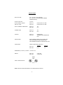
SPECIFICATIONS
INPUT VOLTAGE
100 – 130 VAC, 60 HZ ( PRE-SET )
200 – 260 VAC, 50 HZ ( REQUIRES INTERNAL
JUMPER SETTING )
OUTPUT VOLTAGE
13.8 VDC
OUTPUT RIPPLE & NOISE
(ON FULL LOAD)
SEC-1212
SEC-1223
LESS THAN 10 mV RMS
LESS THAN 15 mV RMS
OUPUT CURRENT, CONTINUOUS
SEC-1212
SEC-1223
10 A
23 A
CURRENT LIMIT
SEC-1212
SEC-1223
14 A
25 A
COOLING
SEC-1212
SEC-1223
CONVECTION
TEMPERATURE CONTROLLED
FAN
PROTECTIONS
OVER CURRENT, SHORT CIRCUIT AND OVER
VOLTAGE (THROUGH PWM CONTROLLER ).
OVER TEMPERATURE SHUT DOWN FOR SEC-1223
FUSE RATING
5 MM X 20 MM GLASS FUSE, 250 V
SEC-1212
SEC-1223
120 VAC
3A
6.3 A
DIMENSIONS ( W X D X H ), INCHES 7.0 X 8.25 X 2.2
WEIGHT
SEC-1212
SEC-1223
3 LBS. NET
3.5 LBS. NET
LISTED
6G18
SAFETY CERTIFICATION
E179076
NOTE : SPECIFICATIONS ARE SUBJECT TO CHANGE WITHOUT NOTICE
7.
240 VAC
2A
4A
3 YEAR Limited Warranty
SEC-1212/SEC-1223 manufactured by Samlex America, Inc. ( the “ Warrantor “ ) is warranted
to be free from defects in workmanship and materials under normal use and service. This warranty is in effect for 3 years from the date of purchase by the user ( the “ Purchaser “ )
In any case part of the equipment proves to be defective, the purchaser should do the
following :
1.
2.
3.
Prepare a written statement of the nature of the defect to the best of the Purchaser’s
knowledge, and include the date of purchase, the place of purchase, and the Purchasers
name, address and telephone number.
Call Samlex America, Inc. 1-800-561-5885 or 1 (604) 525-3836 and request a returning
merchandise authorization number ( RMA ).
Return the defective part or unit along with the statement at the Purchaser’s expense to
the Warrantor ; Samlex America Inc., #110 - 17 Fawcett Road, Coquitlam, B.C. V3K 6V2
Canada. The RMA number must be marked clearly on the outside of the packaging.
If upon the Warrantor’s examination the defect proves to be the result of defective material or
workmanship, the equipment will be repaired or replaced at the Warrantor’s option without
charge, and returned to the Purchaser at the Warrantor’s expense.
No refund of the purchase price will be granted to the Purchaser, unless the Warrantor is unable to remedy the defect after having a reasonable number of opportunities to do so.
Warranty service shall be performed only by the Warrantor. Any attempt to remedy the defect
by anyone other than the Warrantor shall render this warranty void.
There shall be no warranty for defects or damages caused by faulty installation or hook-up,
abuse or misuse of the equipment including exposure to excessive heat, salt or fresh water
spray, or water immersion.
No other express warranty is hereby given and there are no warranties which extend beyond
those described herein. This warranty is expressly in lieu of any other expressed or implied
warranties, including any implied warranty of merchantability, fitness for the ordinary purposes
for which such goods are used, or fitness for a particular purpose, or any other obligations on
the part of the Warrantor or its employees and representatives.
There shall be no responsibility or liability whatsoever on the part of the Warrantor or its employees and representatives for injury to any persons, or damage to person or persons, or damage to property, or loss of income or profit, or any other consequential or resulting damage
which may be claimed to have been incurred through the use or sale of the equipment, including any possible failure of malfunction of the equipment, or part thereof.
The Warrantor assumes no liability for incidental or consequential damages of any kind.
8.
Thank you for purchasing a Samlex power supply product !
Samlex America Inc.
110 –17 Fawcett Road
Coquitlam, B.C. V3K 6V2
Canada
Ver.A(042001)