1
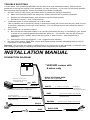
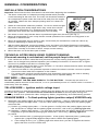
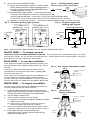
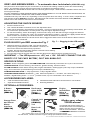
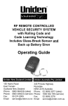
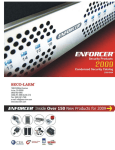
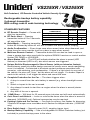
® VS235XR / VS255XR Self-Contained, RF Remote-Controlled Vehicle Security System Rechargeable backup battery capability 3-channel transmitter With rolling code & code learning technology STANDARD FEATURES VS235XR / VS255XR COMPARISON CB A VS235XR VS255XR l RF Remote Control — Comes with Flashing Light Relay Output l slim-line transmitter. Door Lock/Unlock Output l l RF Panic Alert — Pressing Alarm Status LED l l transmitter button #1 for 3 seconds Negative Door Input l l will sound the siren. Number of Wires 6 9 l Quiet Mode — Pressing transmitter button #2 followed by button #1 will arm or disarm the alarm without chirping. l Audio Confirmation — Siren chirps once when armed, twice when disarmed, and three times for zone override (such as a door is open when armed). l Multi-use Remote Control — Transmitter button #2 can also be used to open or close a garage door when used with the optional SEA910 receiver or control another Uniden VS1100XR or VS2100XR. l Alarm Status LED — The LED will indicate whether the alarm is armed (LED flashes) or disarmed (LED is off), also which sensor was triggered. l Unique Built-In Electromagnetic Shock Sensor (with pre-intrusion feature) Revolutionary sensitivity-stable design ensures the sensor never needs readjusting once it is installed. Constructed to eliminate contact problems associated with corrosion, cold-soldering, and condensation. If there is a light shock to any part of the vehicle, the siren will "chirp," but the alarm will not trigger. If a harder impact is made to the vehicle, it will trigger the alarm and sound the siren. l Complete Protection for the Car — The alarm triggers when: 1. A drop in current from the car's battery is sensed (e.g. when domelight comes on). 2. Shock or impact to the car is sensed. 3. Any attempt is made to start the car engine when the alarm is armed (starter sensing). 4. Any door of the car is opened. l 115dB Siren — Will blast for 25 seconds upon intrusion and will reset automatically. l Car's Door Lock/Unlock — Locks or unlocks the doors when the alarm is armed or disarmed. (VS255XR only) Optional accessories may be required. l Parking Lights and Car Locator — One flash for arming, two flashes for disarming, 3 flashes for tamper zone overridden and 4 flashes for tamper indicator. (VS255XR only) l Door Switch Input — Normally-open (N.O.) negative trigger input. l Backup Battery Capability — Use a rechargeable 9V Nickel-Cadmium battery (not included) to provide backup power to the alarm. OWNERS MANUAL ARMED When button #1 is pressed, the siren chirps and parking lights flash once, and the LED starts flashing to show the alarm is armed. (No lights flash for the VS235XR.) ZONE BYPASS When you press transmitter button #1 to arm the alarm, and the alarm responds with three chirps and three light flashes (no flashes for the VS235XR), there are two possibilities: A. Delayed domelights — If your domelights do not immediately turn OFF when you close your car door (in other words, your vehicle has delayed domelights), it is normal to hear the three chirps. The alarm should protect all the openings once the domelights go OFF. B. A zone was bypassed — In other words, the alarm has armed, but a door may not be protected (either because it is open, or because its pin switch is broken). If the bypassed door is later closed, it will be restored. If your alarm indicates a bypassed zone, find the cause as soon as possible to ensure your vehicle is completely protected. For instance, if your driver's door is not properly closed when you arm your alarm, a thief may be able to open any door without setting off the alarm. NOTE — Make sure your car's domelight switch is not in the ON position when you arm your alarm. The alarm may not arm properly if the domelight switch is left ON. NOTE — There are references to opening or closing a door throughout this manual. "Door" also includes your Boot or Bonnet, if they are protected. Ask your dealer. NOTE — The chirps to confirm zone bypass will not sound if chirp delete is engaged. However, the parking lights (VS255XR only) will still flash three times. (See CHIRP DELETE). SENSOR BYPASS (Shock Sensor) This is useful if you know, based on experience, that your shock sensor will false trigger, such as when you park near a construction site. Should you wish to bypass your alarm's shock sensor, first press button #1 to arm the alarm. The siren chirps and the parking lights flash once (three times if a zone is bypassed) (no flash for the VS235XR) to confirm armed. Within three seconds, press button #2. The siren chirps three times and the parking lights flash three times (no flash for the VS235XR) to confirm shock sensor is bypassed. The sensors are automatically restored the next time button #1 is pressed. NOTE — The chirps to confirm zone bypass will not sound if chirp delete is engaged. However, the parking lights (VS255XR only) will still flash three times. (See CHIRP DELETE). DISARMING Press transmitter button #1. You will hear two chirps. The red LED will stop flashing. The parking lights will flash twice, at the same time the car doors will be unlocked (VS255XR only). The alarm is now completely disarmed. EMERGENCY DISARM If you lose your transmitter, you can disarm your alarm with the ignition key switch. While your alarm is either armed or triggered, turn the ignition switch ON/OFF 4 times within 15 seconds. The siren and the flashing lights stop if the alarm was triggered, and then chirp and flash three times. The alarm is now in valet (see VALET). (No lights flash for the VS235XR.) EMERGENCY CALL FOR HELP (panic) To trigger the alarm in an emergency, press and hold transmitter button #1 for 3 seconds. The siren sounds and the parking lights flash for about 30 seconds. Stop the siren and the parking lights any time by pressing button #1 again. (No lights flash for the VS235XR.) If the alarm was disarmed when you triggered the emergency call for help, the alarm immediately arms and the doors lock. If the alarm was armed, the opposite will occur. TOTAL PROTECTION While your alarm is armed, your car is protected in the following ways: l Potential thieves or vandals should be deterred by the flashing LED. l If anyone opens a door, the alarm will immediately sound the siren and flash the parking lights (VS255XR only) for 30 seconds, after which the alarm will rearm, bypassing any open doors. l l l Turning the ignition key ON will trigger the alarm for 30 seconds. The optional Engine Immobilizer prevents the car from being started. If the shock sensor detects light taps on the car, it will trigger the pre-intrusion alert (the siren chirps three times, and the parking lights flash three times [lights flash for VS255XR only]) to warn potential thieves and vandals. However, if the shock sensor detects a strong shock to the car, such as shock caused by prying the Boot open, it will trigger the alarm for 30 seconds. (See DUAL-STAGE SHOCK SENSOR.) CHIRP DELETE (silent arm/disarm) There are times, especially at night, when you may not want to hear the siren chirps. Just press button #2 any time before you need the chirps deleted. For instance, press button #2 before you press button #1 to arm or disarm the alarm, and the chirps will not sound, but the parking lights will still flash (lights flash for VS255XR only). The chirps are restored the next time you press a transmitter button. NOTE — This function deletes the chirps for disarm, zone bypass, sensor bypass, valet, and tamper. However, it does not affect the flashing parking lights. (VS255XR only) VALET Sometimes you may not wish to arm your alarm when you leave your vehicle. (For instance, if you leave your car with a valet attendant, you may not want to teach him how the alarm operates.) To enter valet, first disarm the alarm and turn the ignition ON/OFF 4 times within 15 seconds. The alarm is now in the valet mode. The siren chirps and the parking lights flash once to confirm (lights flash for VS255XR only). Your alarm also goes into valet when you use emergency disarm. (See EMERGENCY DISARM). To exit valet, just turn the ignition ON/OFF 4 times within 15 seconds. The siren chirps twice and the parking lights flash twice (lights flash for VS255XR only) to confirm valet is exited and the alarm is disarmed. If you press transmitter button #1 while the alarm is in valet, the alarm will not arm but the doors will lock or unlock, and the parking lights will flash four times (VS255XR only). The alarm's emergency call for help operates normally. DUAL-STAGE SHOCK SENSOR Your alarm includes a patented dual-stage shock sensor. The first stage (pre-intrusion alert) warns thieves the alarm is armed. For instance, the alarm will chirp three times and the parking lights will flash three times (lights flash for the VS255XR only) if the sensor detects a light bump to the vehicle. However, if the thief attacks the car with sufficient force, the alarm will trigger. Your dealer can make the shock sensor more or less sensitive to attack, depending on your vehicle. POWER DOOR LOCKS (VS255XR only) With this optional feature, your alarm can automatically lock the doors when armed and unlock the doors when disarmed. The doors lock and unlock any time transmitter button #1 is pressed (exception — See EMERGENCY CALL FOR HELP ). For extra security, they lock automatically if the alarm is triggered. Extra accessories may be required, i.e. SEA169 Interface, SEA170 Door Motor. ENGINE IMMOBILIZER SEA865 With this optional feature, while your alarm is armed, your car will not start. TAMPER INDICATOR If your alarm was triggered when you were away, the siren will chirp four times and the parking lights flash four times, then turn ON for 6 seconds when you disarm your alarm. These "memory" flashes automatically reset when the ignition is turned ON. OPTIONAL BACKUP BATTERY With main power disconnected, the backup battery will normally last for at least 24 hours, assuming the alarm was not triggered. If triggered continuously, it would last for approximately 6 minutes. A 9V rechargeable Nickel-Cadmium battery must be used. The alarm will recharge the battery automatically. CODE LEARNING The alarm can learn a maximum of 4 remotes. RF CodeWash™ deletes all previous remotes when any new remote is learned. This prevents unauthorized use of lost or stolen transmitters, and alerts the user if someone has secretly code- learned a new transmitter. However, it also means that, when code-learning is being done, ALL THE USER'S TRANSMITTERS MUST BE CODE LEARNED AT THE SAME TIME. A. Procedure: (1) Disarm the alarm. (2) Turn the ignition switch ON/OFF 4 times within 15 seconds. (3) Within 15 seconds, hold the first transmitter, and then push buttons #1 and #2 together until 1 chirp confirms the code is learned (approximately 4 seconds), and that all previous transmitter codes have been deleted. If no button is pressed within this 15-second period, code learning is exited, and the old codes are retained. (4) Within 15 seconds, push button #1 and #2 of the second transmitter (if available) together for at least three seconds. One chirp confirms learned. (5) Repeat step (4) until a maximum of 4 transmitters are learned. The siren chirps once for each transmitter when its code is successfully learned. B. Exit the code learning procedure — The alarm chirps the siren three times, exits the code learning mode, and is disarmed if you learn the fourth transmitter's code, or if you turn the ignition switch ON, or if you do nothing for 15 seconds. Appendix 1 — UNDERSTANDING THE SIREN CHIRPS AND LIGHT FLASHES NOTE: Lights flash for the VS255XR only. A. 1 chirp/flash: l When transmitter button #1 is pressed, the alarm is armed. l Successfully entered the valet mode. B. 2 chirps/flashes: l When transmitter button #1 is pressed, the alarm is disarmed. l Successfully exited the valet mode. C. 3 chirps/flashes: l Pre-intrusion warns potential thieves or vandals who trigger the first stage of the dual-stage sensor that your car is protected by an alarm. l When pressing transmitter button #1 to arm the alarm, indicates the alarm arms even though it is not set properly (door not closed, or broken switch, or domelight is still ON, see ZONE BYPASS). l When pressing transmitter button #1 then #2, indicates sensor bypassed (see SENSOR BYPASS). l Completed emergency disarm. D. 4 chirps/4 flashes: l When the alarm is disarmed, indicates the alarm was triggered while you were away. l When transmitter button #1 is pressed, indicates the alarm in valet (flashes only, no chirps). Appendix 2 — UNDERSTANDING THE LED FLASHES A. B. C. D. Armed indicator — Flashes when the alarm is armed. Disarmed indicator — OFF when the alarm is disarmed. RF reception indicator — ON while the transmitter button is pressed. Valet mode indicator — Flashes slowly if the ignition switch is turned OFF (no flash if the ignition is ON). Trigger zone indicator If the alarm has been activated while you were away, the LED will flash a code for 30 secs. after the alarm has been disarmed. EG... 1 flash — current sensor activation SEA933 2 flashes — ignition/panic activation 3 flashes — shock activation 4 flashes — door /boot activation CHANGING THE TRANSMITTER BATTERY 1. 2. 3. 4. Unscrew the small screw and remove the top cover. Check that the battery clips are properly contacting the positive (+) and SEA172 negative (-) ends of the battery. Reset the alarm by pressing the small button #1 on the left of the circuit board near the LED. If the alarm still does not operate properly, replace the battery. DO NOT TOUCH ANY OTHER PARTS OF THE TRANSMITTER. MAKE SURE THE POSITIVE AND NEGATIVE BATTERY ENDS CORRESPOND CORRECTLY TO THE POSITIVE AND NEGATIVE BATTERY CLIPS. Replace the front cover and the screw. Turn the screw tight enough to hold the case together, but not so tight that the case cracks. TROUBLE SHOOTING In most cases, rare operational difficulties are the result of a weak transmitter battery. Below are the guidelines for solving the majority of the problems you may encounter. If you have not solved the problem after following these guidelines, contact a professional installer immediately. 1. No siren sound or chirp when transmitter button is pressed for arming or disarming: a. Make sure the alarm's RED wire has power, and the BLACK wire is properly grounded. b. Replace the transmitter battery and check the clips for proper polarity. c. Recode the remote — see "Code learning." 2. Transmitter works in some areas and not in other areas: This is probably due to excess RF activity in that area (usually just a short time and only while you are in that area, depending on the type of the activity). It is only temporary and won't affect the alarm in other areas. 3. Alarm sounds for no apparent reason: a. Be sure that the transmitter button #1 is not being held down too long, or something in your pocket or purse is not pressing against the transmitter button #1. The receiver may also be picking up interference from a nearby airport, low-flying plane or other sources. Such interference is temporary. b. Check which zone was triggered — see "Triggered zone indicator." 4. No chirp when arming, (lights flash 4 times and central locking operates VS255XR) Refer to VALET instructions to exit Valet Mode. Important: Do not make any repairs or adjustments to any component of the transmitter or the alarm other than changing the battery or checking the shock sensor adjustment as described. INSTALLATION MANUAL CONNECTION DIAGRAM * VS235XR comes with 6-wires only BLACK ANTENNA WIRE Positive (+) terminal (Unswitched, constant, +12VDC input) (Do not cut or ground) RED 15A YELLOW WHITE Ignition switch (switched +12VDC input must have voltage during ignition and start) To parking light Relay voltage output (10A max.) Tr. GND. 0.5A output GREY 10A To Engine Immobilizer relay terminal #85 Lock 0.5sec. GND. output 0.3A (VS255XR only) ORANGE (VS255XR only) BROWN BLACK Unlock 0.5sec. GND. output 0.3A (VS255XR only) Chassis ground BLUE Negative door switch BLACK/RED Arm LED GENERAL CONSIDERATIONS INSTALLATION CONSIDERATIONS Important: Disconnect the fuse from alarm's red wire before beginning the installation. 1. The alarm comes with a U-shaped mounting bracket which provides a solid mounting for the main unit. The main unit should be located in an inconspicuous place under the hood as far away from the engine IMPORTANT as possible. Mount the siren trumpet pointing down so it does not collect water. 2. Solder all connections whenever possible. Do not run wires too tight. 3. Run wires away from sharp edges which may cause short circuits. Protect wires with tubing or by wrapping with electrical tape. Use Fig. 1 grommets when wires are run through holes in the car body. 4. Run wires in such a way that the alarm is positioned higher than the wires (see Fig.1). 5. Mount all components in such a way that the normal operation of the vehicle’s moving parts is not impaired or interfered with. 6. Mount all components and run wires so they cannot easily be reached from under the vehicle by someone attempting to defeat the system. 7. With the alarm disarmed, remove the battery cover and insert a 9V Nickel-Cadmium rechargeable battery (not included) to provide backup power to the alarm. If the main power cord is cut, the alarm will function normally for at least 24 hours, except current sensing. 8. Mount the siren out of the direct path of water. TECHNICAL NOTES WHEN USING CURRENT SENSING (If current sensing is not desired, cut the purple loop in the unit) 1. If the vehicle has a built-in noise filter that prevents the current sensing function from triggering the alarm, use a charged non-polarized capacitor (not included) of at least 47µF rated at 16V or higher. Connect it in parallel to the dome or courtesy light. 2. False alarms may result if the alarm is over-sensitive, or if a built-in electrical device drains the battery when the vehicle is parked. In this case: a. Connect one lead of a non-polarized capacitor to where the alarm's red wire connects to power. Connect the other lead of the capacitor to the chassis. b. For vehicles with a built-in impulse winding clock that draws current when the clock is winding, replace it with a constant-current clock or connect it to a separate battery. RED WIRE — Main power DO NOT CONNECT THE RED WIRE DIRECTLY TO THE BATTERY. Connect the red wire to an unswitched positive terminal of the fuse box, or to an (unswitched) source of +12VDC which is at least 1 meter away from the battery. YELLOW WIRE — Ignition switch voltage input Connect to a fuse or a wire which outputs +12VDC when the ignition key is in the ON and START position, but not the ACC position. This wire must be connected at all times to ensure proper arming and disarming, as well as to operate the valet, emergency disarm, programming, and code learning process. ORANGE WIRES — To flash parking lights (positive output) VS255XR only A. Determine if the parking lights are positive or negative switched — Using a VOM meter, test the wires coming from behind the light switch. Look for a wire which changes polarity when the parking lights are turned ON: (1) Positive (+) parking light system — If a wire goes to +12VDC when the parking lights are turned ON, but shows no voltage with the parking lights turned OFF, this is the (+) parking light wire. (2) Negative (-) parking light system — If a wire goes to ground when the parking lights are turned ON, but shows no ground with the parking lights turned OFF, this is the (-) parking light wire. (3) NOTE: a. Most vehicles have (+) parking light systems. A few (mainly Japanese) have (-) parking light systems (the (-) signal usually triggers a relay to send +12VDC to the parking lights). b. If the voltage on the (+) or (-) parking light wire varies when you dim or brighten the interior lights, then this is not the correct wire. B. Connect the fused ORANGE WIRE: Fig. 2 — Flashing parking lights (1) Single-wire parking light systems — Most vehicles Positive single-circuit parking lights have a single circuit which controls all parking lights. In this case, connect the fused ORANGE WIRE to the 10A Ø ORANGE (+) parking light wire. See fig. 2. (2) Dual-wire parking light systems — A few vehicles (mainly European) have separate circuits for parking lights for the vehicle's right and left sides. In this case, connect the fused ORANGE WIRE to two relays, each of which feeds power to the two separate circuits. See fig.3. (3) Negative (-) parking light system — Connect the fused ORANGE WIRE to a relay. See fig.4. Fig. 3— Dual-wire parking light systems SP898 SP898 Fig. 4— Negative single-wire parking light system ** DIODE SP898 (optional) To ORANGE WIRE To ORANGE WIRE 10A 87 10A 87a 86 85 30 SEA865 SEA865 SEA865 Note: Uniden SEA865 relays already have the optional SP898 diodes fitted. BLACK WIRE — To chassis ground CHOOSE A GOOD CHASSIS GROUND LOCATION. If the ground is not connected properly, the alarm may act as if armed, but not be able to sound the siren. Scrape paint from the metal surface, and use a grounding lug and star washers for best results. BLUE WIRE — To car door switches If the vehicle has existing car door switches, locate a car door switch wire which changes polarity when any door is opened: If the door switch wire shows ground when a door is opened (this is the case with most cars, including GM), connect to the blue wire. If the vehicle is not equipped with car door switches, or if the door switch wire shows positive when the door is opened, install pin switches SEA876 in each of the doors. Connect each of these switches to the alarm's BLUE wire. WHITE WIRE — To engine immobilizer Connect to an optional 30A relay SEA865 to prevent the car from starting when the alarm is armed. A. Locate the starter solenoid wire (carries power from the ignition switch to the starter solenoid). This wire must show +12VDC only when the ignition is in the start position. B. Cut the starter solenoid wire. C. Test the starter solenoid wire as follows: (1) If the wire is cut before the engine is started, the engine should not turn over. (2) If the wire is cut while the engine is running, it should not affect the engine’s operation. D. Connect the WHITE WIRE and the two halves of the cut starter solenoid wire to the relay as shown in fig. 5. E. If the engine still starts, connect terminal 86 to a wire which shows +12VDC when the engine is both starting and running (fig. 6). Fig. 5— N.C. Engine Immobilizer output SP898 SEA865 Ignition switch To alarm WHITE engine immobilizer output wire Starter solenoid Fig. 6— Alternate N.C. Engine Immobilizer SP898 SEA865 Ignition switch To alarm WHITE engine immobilizer output wire Starter solenoid GREY AND BROWN WIRES — To automatic door lock/unlock (VS255XR only) The power door lock outputs may be connected to a car which has existing or add-on power door lock switching relays. The transistor ground output is high enough to energize most switching relays. When disarmed, UNLOCKS the doors with a 0.5 second ground output. When armed, LOCKS the doors with a 0.5 second ground output. DO NOT CONNECT THESE POWER DOOR LOCK WIRES DIRECTLY TO THE DOOR LOCK ACTUATORS, AS THIS WILL DEFINITELY BURN OUT THE ALARM SYSTEM. Installation will vary from car to car, depending on the car's power door lock wiring. In most cases, a separate door lock interface module SEA169 is required. Mercedes and Audi owners will need a different model (SEA168). Please refer to the module's manual for more information. ADJUSTING THE SHOCK SENSOR 1. 2. 3. 4. Remove the back cover. Use a small, flat-blade screwdriver to turn the adjustment knob. When turned clockwise, the sensitivity is increased. If turned counterclockwise, the sensitivity is decreased. Do not overturn the potentiometer, as it may break, only 270 degree adjustment range. To test the sensitivity, kick a wheel lightly, and siren will "chirp," then kick hard enough to trigger the alarm at the desired point. If it does not "chirp," the sensitivity should be increased. If the wheel is lightly kicked and the alarm sounds, the sensitivity should be decreased. Check all wheels for consistency. Note — To prevent false alarms, the shock sensor will not trigger the alarm until 4 seconds after the alarm is armed and no further motion is detected. PLUG-IN LED 2-pin RED connector Fig. 7 Fig. 7 — Plugging in the LED switch LED A. Determine where to mount the LED. The LED should be easily seen by potential thieves and vandals. However, do NOT mount where the LED is easily exposed to SEA110 sunlight. Discuss the LED location with the customer before starting. B. Drill a 6 mm hole in the LED location. C. Run the LED connector through the hole, and then plug into the alarm brain’s 2-pin RED connector. IMPORTANT The LED operates on +5V, not +12V. DO NOT CONNECT THE LED DIRECTLY TO THE CARS BATTERY, OR IT WILL BURN OUT. SPECIFICATIONS POWER: 12VDC. Negative ground ALARM DURATION: Automatically resets after one cycle of 30 seconds TRIGGER INPUTS: Current sensing, shock sensor, ignition sensing, and door switch ALARM OUTPUTS: Alarm status arming LED, engine immobilizer, flashing lights (10A relay output, VS255XR only), door lock/unlock (0.3A transistor ground output, VS255XR only) ARM/DISARM INDICATOR: 1 chirp signals arm, 2 chirps signals disarm TRANSMITTER/RECEIVER: Modulation — AM; Antenna impedance — 50 ohms; RF carrier frequency — 304MHz; Digital Rolling Code — 1.8 x 10¹⁹ possible codes, up to 4 transmitters can be learned. ACCESSORIES INCLUDED: a. 2 RF transmitters with battery b. Siren/alarm brain and built-in shock sensor in one module c. Operation/Installation manual d. Mounting hardware OPTIONAL ACCESSORIES: 3 Button Remote (SEA933) Garage Door and House Alarm Interface (SEA910) Dual-stage glass-break sensor (SEA857) Central Lock Interface (SEA169) and Door Lock Motor (SEA170) Engine Immobiliser Relay & Socket set (SEA865) Make your alarm YOUR alarm! Your dealer has a wide variety of accessories which can increase your alarm's security and convenience. Ask for more information. And insist on GENUINE UNIDEN accessories! The Uniden policy is one of continual development and improvement. For that reason, Uniden reserves the right to change specifications without notice. FILE: DTP\MANUAL\VS235255XRInstMenuVer1b.P65\MAY2000 ORDER PART# 760-899-2\909