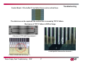
1
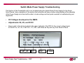
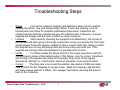
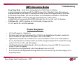
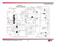
Troubleshooting
50PC1DR
Plasma Display Panel Troubleshooting - 2007
1
Troubleshooting
Overview of Topics to be
Discussed
•Switch Mode Power Supply
•Y SUS Board
•Z SUS Board
•X Drive Boards
Plasma Display Panel Troubleshooting - 2007
2
Safety Rules
PLASMA Overview
Troubleshooting
Safety & Handling Regulations
1. Approximately 10 minute pre-run time is required before adjustment.
2. Do not exceed Higher voltage than is required for the product.
3. Be cautious of electric shock from the PDP module since the PDP module uses high voltage, and it is
recommended that you should not touch the drive circuits for at least one minute because of residual
current stored.
4. Circuit drive has c-mos circuits which should be protected from static electricity.
5. The PDP Module must be carried by two people.
6. Be careful of short circuit when measuring voltage.
7. Be cautious of screws and other metal objects to prevent short in circuitry.
Checking Point before Requesting MODULE Repair
1. Check the appearance of Panel and boards.
2. Check the model label. Verify model names and board model matches.
3. Check details of defective condition and history.
Ex) COF long 2-1 fail, address 1 line open, Y b/d trouble, Mal-discharge on screen.
Plasma Display Panel Troubleshooting - 2007
3
Switch Mode Power Supply Troubleshooting
This Section of the Presentation will cover troubleshooting the Switch Mode Power Supply for the Single
Scan Plasma. Upon completion of the section the technician will have a better understanding of the operation
of the Power Supply circuit and will be able to locate voltage and test points needed for troubleshooting and
alignments.
•
•
DC Voltages developed on the SMPS
Adjustments VA, VS, and 5V DC
•
Always refer to the sticker located in the upper right side of the PDP for the correct voltage levels
for the DC 5v, VA, VS, V SET UP, -VY, VSC, and Z Bias as they will vary from Panel to Panel.
V SET_UP
-VY
Plasma Display Panel Troubleshooting - 2007
VSC
4
Z_BIAS
Troubleshooting Steps
•
•
•
•
Define
Look at the symptom carefully and determine what circuits could be
causing the failure. Use your senses Sight, Smell, Touch and Hearing. Look for
burned parts and check for possible overheated components. Capacitors will
sometimes leak dielectric material and give off a distinct odor. Frequency of power
supplies will change with the load, or listen for relay closing etc.
Localize
After carefully checking the symptom and determining the circuits to
be checked and after giving a thorough examination using your senses the first check
should always be the DC Supply voltages to those circuits under test. Always confirm
the Supplies are not only the proper level but be sure they are noise free. If the
supplies are missing check the resistance for possible short circuits.
Isolate
To further isolate the failure check for the proper waveforms with the
Oscilloscope to make a final determination of the failure. Look for correct Amplitude
and Timing of the signals also check for the proper Duty Cycle of the signals.
Sometimes “glitches” or “road bumps” will be an indication of an eminent failure.
Correct
The final step is to correct the problem. Be careful of ESD and make
sure to check the DC Supplies for proper levels. Make all necessary adjustments
and lastly always perform a Safety AC Leakage Test before returning the product
back to the Customer.
Plasma Display Panel Troubleshooting - 2007
5
SMPS Operating Modes
•
Troubleshooting
Deep Sleep Mode - Guide Plus not programmed or Cable Card not installed
and set is plugged in and turned off. The SMPS outputs S 5v (Standby). Guide Plus has been
programmed the set will remain in Standby Mode when turned off for approximately 2 hours and
go into Deep Sleep Mode. The unit can be taken out of DS Mode as needed for TVGOS Data.
Standby Operation - Guide Plus has been programmed or a Cable Card is
installed and unit is powered off the SMPS will output 19v,12v, 6v, 5vS, and 3.3v Supplies.
Full Power On - SMPS outputting all of the Standby Voltages and the
VA, VS, and 5v DC, set in full operation.
•
•
Power Sequence
•
•
•
•
•
•
AC Cord Plugged in – Standby 5v
AC Detect sent from the Power Board Pin1 of P800 to the Digital Board. Needed to enable the
Micro Processor to output the RL-ON Signal to turn on the SMPS.
Digital Board sends RL-ON to P800 Pin 2 to cause Controller IC U701 on the Power Board to
turn on the Relay Drive Transistors Q701 and Q702 closing the Relays RL101 and RL102 turning
on the 3.3V, 5V, 6V, 12V, and 19V supplies.
VS-ON applied from the Digital Board to the Power Board on connector P800 Pin 5 used to turn
on the VA, and VS Supplies
5V-M Sent from the Digital Board to the Power Board to turn on 5V-DC.
5V-D is sent from the Digital Board through P800 Pin 6 and used to bring the Power Supply out of
Deep Sleep Mode.
Plasma Display Panel Troubleshooting - 2007
6
Switch Mode Power Supply (SMPS) Voltages
•
•
•
•
•
•
•
•
•
•
•
Troubleshooting
VS 196v used to drive the Horizontal Grid Voltage, Y SUS, and Z SUS. Measured from pins 8, 9,
and 10 of connector P805 to chassis ground. Adjusted at VR951
VA 60v used to drive the Vertical Grid Voltage, X Boards and in the IPM Circuits to develop Y and Z
Drive waveforms. Measured from pins 1 and 2 of connector P805 to chassis ground. Adjusted at
VR901
5v.DC Used to develop bias voltages for the circuits on the Y SUS, Z SUS, X, and Control Boards.
Measured from pins 1 and 2 of connector P804 to chassis ground.
3.3v. Standby voltage applied to the Analog, and Digital Boards to Bias the Signal and Control
circuits. Measured at connector P803 at pins 1 and 2. to chassis ground. Adjusted at VR221.
19v Applied to the Analog Board and used for the Audio Output Supply, present in standby.
Measured at P802 pins 1 and 2 to chassis ground.
12v Used for supplying low voltage regulators on the Digital and Analog Boards, present in standby.
Measured at P803 pins 9 and 10 to chassis ground.
6v Applied to the Digital Board used for the signal processing circuits present in standby. Measured
at P803 pins 5 and 6 to chassis ground.
S 5v Standby 5 volts at P800 pin 3 applied to the Digital Board.
VS- ON Switched 5 volts at P800 pin 5 present after power up to switch on the VA, VS, and 5V on
the Power Board from the Digital Board.
5v-D Switched 5v used to bring the Power Supply out of Deep Sleep Mode.
5V-M Needed to turn on the 5V-DC Supply.
Plasma Display Panel Troubleshooting - 2007
7
Power Supply
VS Adjust
Troubleshooting
VA
Adjust
VS
VA Source
VA
380 Volt Supply
5v
VS Source
Control IC
19v Audio Supply
12V,6V, 5V and
3.3V Source
3.3v
Adjust
Standby Circuit
P802
P803
AC Input Circuit
P800
Plasma Display Panel Troubleshooting - 2007
8
Troubleshooting
Power Supply
Low Voltage Connectors
P800
P800
1) AC-D
2) RL-ON
3) S-5V
4) GND
5) VS-ON
6) 5V-D
7) M5V-ON
8) S-5V
9) GND
10) NC
11) 6V
12) N.C
13) 3.3ON
PIN1
P803
PIN 1
P802
PIN 1
Plasma Display Panel Troubleshooting - 2007
9
P803
1) 3.3V
2) 3.3V
3) GND
4) GND
5) 6V
6) 6V
7) GND
8) GND
9) 12V
10) 12V
11) GND
12) GND
P802
1) 19V
2) 19V
3) GND
4) GND
5) 6V
6) GND
7) 3.3V
8) GND
9) 12V
10) GND
Power Supply Voltage Distribution
Troubleshooting
Q801
HS2
HS3
PC901
HS4
U801
Q607
VS
D951
T801
D952
Q606
R606
R607
U851
Q854
T902
R963
VA
Q601
D953
L851
Q602
P802
Q855
C855
D602
Q281
R162
380V
12V
D261
U151
D601
3.3V
C602
5V
T112
HS6
Q151
Standby
Regulator
U501
C603
P803
3.3V
Q252
U261
Q223
D251
PCs
6V
U601
12V
Control
IC
28
S-5V
24
20
S-5V
D221
D202
Q702
R745
U701
P800
D271
6V
R870
L601
19V
AC DETECT
RL- ON
VS-ON
5V-D
5V-M
S-5V
6V
5V-M
T901
3.3v
R747
Q701
D703
D704
19
D502
Low Voltage
Standby Power
Supply
AC Input
F101
T501
AC
Relay
RL101
HS1
AC
Relay
RL102
D101
120VAC
D506 D501
D102
Plasma Display Panel Troubleshooting - 2007
10
TH01 TH02
AC
INPUT
Circuit
Troubleshooting
Y SUSTAIN BOARD Troubleshooting
This Section of the Presentation will cover troubleshooting the Y SUS Board for the Single
Scan Plasma. Upon completion of the Section the technician will have a better
understanding of the operation of the circuit and will be able to locate voltage and
resistance test points needed for troubleshooting and alignments.
•
•
•
Adjustments
DC Voltage and Waveform Checks
Resistance Measurements
Operating Voltages
Plasma Display Panel Troubleshooting - 2007
SMPS Supplied
VA 60v.
VS 196v.
5v.
Y SUS Developed
VSC 115v.
-VY -196v.
IPM 18v.
ER IPM
SUS IPM
Ramp UP
V SET DN
V SET UP
11
Troubleshooting
Important Note
•
•
The following voltages and waveforms should be adjusted in the order they are presented.
Always adjust the DC levels before the waveform adjustments to most accurately set the Plasma
Display Panel.
Voltmeter Adjustments to Y SUS
•
VSC 115v Used to shape the Y Drive waveform by setting the V Scan level. Measured at the
VSC test points.
•
-VY -196v Used to shape the Y Drive waveform by setting the negative excursion of the V Set
Check Y Sustain Board Output Voltage with the Voltmeter make sure the -VY and VSC are the same
as the Voltage Label on the upper right side of the PDP.
Check -VY
Check VSC
Plasma Display Panel Troubleshooting - 2007
12
Troubleshooting
Waveform Adjustments Y SUSTAIN
• Ramp Up Used to shape the Y Drive Waveform
by changing the pitch of the Top Ramp
• V SET DN Used to shape the Y Drive
Waveform by changing the pitch of the Bottom
Ramp
• V SET UP Used to shape the Y Drive
waveform by leveling the Top Ramp
Plasma Display Panel Troubleshooting - 2007
13
Panel Waveform Adjustment
Troubleshooting Single Scan Panel
*Waveforms may vary with different
Y_SUSTAIN PCB part #’s.
RAMP UP
Normal Waveform
35 micro seconds
Scope TP
-VY
000
180 micro seconds
VSET UP
Ground
This test point is the
reference for all the following
signals referred to here.
Readings are taken with the
probe set to 10x1.
Plasma Display Panel Troubleshooting - 2007
14
VSET DN
+VSC
Troubleshooting Single Scan Panel
Ramp up too high
Panel Waveform Adjustment
Noticeable low level color distortion with the Ramp_up too high.
Ramp up too low
Noticeable low level color distortion with the Ramp_up too low.
Plasma Display Panel Troubleshooting - 2007
15
Troubleshooting Single Scan Panel
Panel Waveform Adjustment
Vset DN too low
The center begins to wash out and arc due to decreased
Vset DN time.
Vset DN too high
All of the center washes out due to increased Vset_DN time.
Plasma Display Panel Troubleshooting - 2007
16
Troubleshooting Single Scan Panel
Panel Waveform Adjustment
Vset UP too high
Vset UP too low
Plasma Display Panel Troubleshooting - 2007
The center begins to wash out and arc due to Vset UP
Peeking too late and alters the start of the Vset DN phase.
Very little alteration to the picture, the wave form indicates a
distorted Vset UP. The peek widens due to the Vset UP
peeking too quickly.
17
Troubleshooting Single Scan Panel
Panel Waveform Adjustment
-VY too low (-154vdc)
Colors and the image will bloom slightly and the unit
will have difficulty with clean frame changes in a quickly
altering image.
-VY too high (-227vdc)
Plasma Display Panel Troubleshooting - 2007
The center begins to wash out and arc due to –
VY running to long and clipping.
18
Troubleshooting Single Scan Panel
Panel Waveform Adjustment
VSC too low (77 Volts)
The image will show very little change but there will
Be some distortion in a quickly changing image.
VSC too high (140 Volts)
Plasma Display Panel Troubleshooting - 2007
The image will show very little change but there will
Be some distortion in a quickly changing image.
19
SINGLE SCAN PDP 50PX3
DVM
ZBIAS adjustment: On the Z-Sustain PCB
With the DVM across R92 adjust the potentiometer till the DVM
reads 93 vdc.
Plasma Display Panel Troubleshooting - 2007
20
Troubleshooting
Y sustain board
Control Board supplies Logic Signals to the Y Sustain Board for processing, which then develops the
signal to drive both of the Y Drive Boards sequentially with the Y Output Waveform for PDP operation.
Logic signals from
Control Board
< Probe connect point to Oscilloscope to check Y Drive output wave form to
the Y Driver Boards >
80V
200V
200V
Y
110V
110V
Y Output Waveform
Plasma Display Panel Troubleshooting - 2007
V
s
21
Troubleshooting
Y Sustain Board
Diagram of Y Sustain Board
Power Supply Board - SMPS
Z SUS Board
Distributes 5v VA VS
Receive 5V,Va, Vs
from SMPS
Distributes 5v
Control Board
Distributes 5v VA
Logic signals
needed to
generate drive
waveform
IPM generates
Sustain Waveform
Generates Vsc, -Vy from
5v VA Vs by transformer.
Bottom Left X Board
FETs amplify Sustain
Waveform
Transfer Waveform
to Y Drive Board
Plasma Display Panel Troubleshooting - 2007
22
Display Panel
Troubleshooting
IPM (Intelligent Power Module)
SUS_UP
SUS_DN
ER_UP
ER_DN
There are two IPMs used in 50PC1DR on the Y Sustain Board.
1. SUS IPM (IC202)
2. ER IPM (IC201)
Role of IPMs
1. Generate Sustain Waveform (square wave) – SUS IPM.
2. Energy Recovery Function (for saving power) – ER IPM.
Plasma Display Panel Troubleshooting - 2007
23
SUS_DN
Troubleshooting
How to check IPM
(Resistance ‘Diode Check’, board removed from set)
Forward Test : 1. GND (+), Sus-out ( - )
2. Sus-out (+), Vs ( - )
3. ER-DN ( - ), GRND (+)
4. GRND ( + ), ER-UP ( - )
5. 18v ( - ), ER GRND ( + )
6. 5v ( - ), ER GRND ( + )
Reverse Test : 1. GND ( - ), Sus-out (+)
2. Sus-out ( - ), Vs (+)
3. ER-DN (+), GRND ( - ) 1.4
4. GRND ( - ), ER-UP ( + ) 1.4
5. 18v ( + ), GRND ( - ) 1.9
6. 5v ( + ), GRND ( - ) .9
Note: ER_HIGH ER_LOW, to ER_lO OPEN in Diode Check
Plasma Display Panel Troubleshooting - 2007
24
Troubleshooting
▶ Major defect : IPM fail, FET fail, fuse
Defect name
Description of defect
IPM Fail
No display
( If the ER IPM failed,
The screen can display
normal picture for few
minutes)
(If SUS IPM failed, top
portion of Drive
Waveform will be
missing )
FET Fail
Fuse
Part
Defect display
`
< No display >
No display
( loss of Drive Waveform
- Power FETs on Y
Sustain Board )
No display
* 5V- SMT fuse
* Va, Vs fuse-ceramic
fuse
Va
Vs
5V
Plasma Display Panel Troubleshooting - 2007
25
Troubleshooting
Y SUS
Plasma Display Panel Troubleshooting - 2007
26
P11 to Z SUS Board
Y SUSTAIN
5v VA
P3
Troubleshooting
VS
5v
ER_IPM (IC201)
floating ground
Supplies Logic signals to Y
Drive Boards to sequentially
scan the Horizontal Grid
P1
floating ground
VA
Ground
VA, VS, and 5v
all supplied from
SMPS
VS
P5
5v
64v
Ground
SUS_IPM (IC202)
Y SUS output
P6
Ground
5v to the Control Board
64v
P4
Logic signals input
from the Control Board to Y SUS
floating ground
PS101 -VY
Transformer coupled
18v IPM
Measured at
R61
PS102 VSC
Transformer coupled
Oscilloscope
Waveform adjust
test point
5v and VA to X Drive
Board
P2
Plasma Display Panel Troubleshooting - 2007
27
Troubleshooting
Single Scan
Y Drive
Output Waveform
Plasma Display Panel Troubleshooting - 2007
28
Troubleshooting
Resistance Measurements performed with board installed and no power applied (all resistance measurements are approximations)
•
VA
3 Meg measured from chassis ground
•
VS
18 Meg measured from chassis ground
•
5v
2K measured from chassis ground
•
VSC Measure in Diode Mode at VSC TP
•
-VY Measure in Diode Mode at -VY TP
•
Floating Ground to Y Drive input measure in Diode Mode
Y SUSTAIN Board removed from PDP Assembly
(all resistance measurements are approximations)
•
•
•
•
•
•
•
•
•
•
•
•
•
•
•
VS to SUS OUT
SUS OUT to Chassis Ground
SUS_UP(+) SUS_DN(-)
ER_LO to ER10
ER_HIGH to ER10
18v to Chassis Ground
5v to Chassis Ground
ER_UP to Chassis Ground
ER_DN to Chassis Ground
SUS_UP to Chassis Ground
SUS_DN to Chassis Ground
Y SUS out at B1 to Floating Ground
VSC Test Points
-VY Test Points
ER_UP to ER_DN
Plasma Display Panel Troubleshooting - 2007
1 Meg
1 Meg
450K
1 Meg
1 Meg
6K
2 Meg
10K
10K
700K
700K
2 Meg (infinite in Diode Mode)
Measure in Diode Mode
Measure in Diode Mode
20K
29
Y DRIVE BOARD
Troubleshooting
Plasma Display Panel Troubleshooting - 2007
30
Y DRIVE Boards
Y-Drive Board works as a path supplying Sustain waveform and Reset
waveform which is made in Y SUSTAIN B/D to the Panel through SCAN
DRIVER IC
Supplies a waveform which selects horizontal electrode sequentially.
* 50PC1DR uses 12 DRIVER ICs (TOP, BOTTOM: 6 each)
VH
HVO
GND
Plasma Display Panel Troubleshooting - 2007
31
Troubleshooting
Module check point
Troubleshooting
Defect Condition
Visual check of YDT-BTM
Horizontal bar displays across the screen due to no
Scan Pulse caused by Scan IC Failure.
Failures can be found, sometimes by a visual
inspection of the Y DRIVE Board scan IC’s .
Plasma Display Panel Troubleshooting - 2007
32
Defect : Horizontal Bar or Shutdown
Z SUSTAIN Board Troubleshooting
This Section of the Presentation will cover troubleshooting the Z-SUS Board Assembly. Upon
completion of this section the Technician will have a better understanding of the circuit and be
able to locate voltage and resistance test points needed for troubleshooting and alignment.
•
•
•
DC Voltage and Waveform Test Points
Z BIAS Alignment
Resistance Test Points
Operating Voltages
Y SUS Supplied
VA 60v.
VS 196v.
5v.
Developed on Z SUS
Plasma Display Panel Troubleshooting - 2007
33
Z Bias 90v
SUS_IPM
ER_IPM
IPM 18v
Troubleshooting
Input Voltages from the Y SUS Board
VS
Supplied to IC7 the SUS_IPM through coil FL152 and to the Primary Winding of Transformer
T2 of the Z Bias Circuit. Input measured from P151 pin 12 to chassis ground.
VA
Supplied to the ER_IPM through parallel resistors R91 and R9 and through Diode D84. The VA
voltage is also routed to connectors P152 and P153 at pin 7 of each connector. Used to supply
60v to the Center and Bottom Right X Boards. Input measured from pins 8 and 9 of P151 to
chassis ground.
5v
Used to Bias the circuits on the Z SUS Board and through P152 and P153 pins 3 and 4
supplies 5v to bias the Center and Right X Boards. Input measured from P151 pins 1 and 2 to
chassis
Voltages Developed on the Z SUS Board
Z Bias
90v used to Bias the output circuits that drive the Sustain and Erase pulses for the PDP.
Measured across parallel resistors R25 and R111, adjusted at VR3.
IPM 18v
Needed to generate the Sustain and Erase pulses in the IPMs. Measured at right side of
resistor R100 (above capacitor C27).
Plasma Display Panel Troubleshooting - 2007
34
Troubleshooting
Z SUSTAIN Board
IC7 SUS_ IPM
R111, R25 Z BIAS TP
IC5 ER_IPM
Z BIAS
Adjust
Control
VS
P151
P151 and P152
Supplies VA
and 5v to X
Boards
VA
5v
18v IPM at right side of R100
P1 from control board
Timing, Data, and control signals
Plasma Display Panel Troubleshooting - 2007
35
Z SUSTAIN Voltage Distribution
From Y SUS Board
FL152
To X Drive Boards
Plasma Display Panel Troubleshooting - 2007
36
Troubleshooting
Troubleshooting
Waveforms Z SUSTAIN Board
• Input signals to the Z SUS Board at P1 from the Control
Board are routed through IC1 and IC82 to the IPM.
These signals are used to develop the Z SUS Drive
Waveform to drive the PDP.
Plasma Display Panel Troubleshooting - 2007
37
Troubleshooting
Z Board SUS Board
Waveform inputs from the Control Board
NOTE: These voltages will vary due to changes
in design and variations in the PDP panel.
Pin 1
PIN2
PIN5
PIN6
PIN7
PIN8
PIN9
PIN10
PIN11
PIN12
Plasma Display Panel Troubleshooting - 2007
PIN3
PIN4
PIN1
38
Troubleshooting
Z SUSTAIN Board
Provides the SUSTAIN PULSE and ERASE PULSE for generating
SUSTAIN discharge in the panel by receiving LOGIC signals from
the CONTROL B/D.
This waveform is supplied to the panel through FPC(Z).
Z DRIVE Waveform
Z
Vs
< Probe connect point to Oscilloscope
to check Z wave form >
Plasma Display Panel Troubleshooting - 2007
95
V
39
95V
Vs
Troubleshooting
Z SUSTAIN BOARD
Distributes 5v, VA, VS
Y SUS Board
Distributes Logic Signals
Receive 5v, VA, VS
Control Board
Distribute 5v, VA
X Board Center and Right
IPM generates erase,
sustain waveform
Generates Z Bias
FET Makes Drive waveform
Display Panel
Via FPC (flexible printed circuit )
Plasma Display Panel Troubleshooting - 2007
40
Troubleshooting
Z SUS IPM (Intelligent Power Module)
Vs
Z
95V
95
V
Vs
SUS_UP
SUS_DN
ER_UP
ER_DN
There are Two IPM ( Intelligent Power Module) on the Z sustain board
of the 50PC1DR.
One is SUS IPM (IC7) , another is ER IPM (IC5)
Role of IPM
1.Generate sustain and erase waveform( square wave ) – SUS IPM.
2.Energy recovery function ( for saving power) – ER IPM.
Plasma Display Panel Troubleshooting - 2007
41
SUS_DN
▶ Major defect
: IPM fail, cable connection.
Defect name
Description of defect
IPM Fail
Dark display
Part
Troubleshooting
Defect display
< Dark display >
P1 Cable
connection
If the cable was not
connected,
There is no display
Plasma Display Panel Troubleshooting - 2007
< No display >
42
FPC (Flexible Printed Circuit) Removal for Z Board Replacement
Pull out Lock as shown in circles
Pull Lock apart to remove
Troubleshooting
Pull FPC Connector as shown in arrow.
Resistance Measurements
•
•
•
•
•
•
•
•
•
•
•
•
•
VS Started at 340 meg settled approx 1 meg
VA 1.3 meg
5v 1 meg
B10 to Chassis Ground 2 meg
Chassis Ground to SUS_OUT 2 meg
SUS_OUT to VS 1 meg
ER low to ER 10 1 meg
ER 10 to ER High 1 meg
18v to Chassis Ground 6K
SUS_UP to Chassis Ground 700K
SUS_DN to Chassis Ground 2meg
ER_UP to Chassis Ground 10K
ER_DN to Chassis Ground 10K
Plasma Display Panel Troubleshooting - 2007
*Measurements made with the board disconnected
43
Troubleshooting
CONTROL Board
Troubleshooting
Plasma Display Panel Troubleshooting - 2007
44
Troubleshooting
CONTROL Board
◆. In charge of all signal process and creating ON/OFF order of all FET on
DRIVER B/D by receiving 8 bit R, G, B input.
Temperature display diode can
be checked.
Left picture shows 7 periods
◆. Power : 3.3V/5V
which means normal temperature
Temperature
diode
Green = OFF
Yellow = ON
Voltage
Regulator
Flash ROM
TEST Pattern
AUTOGEN
P1 Connector
Voltage
Regulator
MCM
(Micro
Control
Module)
LG Part Number Label
Plasma Display Panel Troubleshooting - 2007
45
Weight
D15 - 8
D16 - 4
D17 - 2
D18 - 1
Control Board
Troubleshooting
1. Check LED ( Normal status lighting or not )
100.0 MHZ
2. CHECK OSC X1 output. (100MHZ)
OSC(X1)
3. Check CTRL input voltage
Check oscillator state.
Be careful to avoid
physical shock.
(CONNECTOR P10)
4. CHECK each FET 3.3V, 5V,1.8V., 2.4V
+5v
Check
FET’s
GND
Probe
Test
3.3vdc
point
1.8vdc
2.4vdc
5vdc
Input
voltage
Plasma Display Panel Troubleshooting - 2007
46
Control Board
Troubleshooting
▶ Main Defect : MCM , connector, oscilator, LVDS poor connection
▶ Voltage used : 5V/3.3V/1.8V/2.5V (4 separate operating voltages).
Defect part
Description of defect
CONTROL IC
Regular vertical
lines
Part
Solution
Replace
Control
Board
< Display Lines >
< MCM >
Connector
Reseat
Control
Board
Connectors
No display or
Partly no display
< Connector >
Oscilator
No picture
< Oscillator >
LVDS
poor connection
Remove LVDS Cable
and short pins 1 and
2 of connector P1 to
display test patterns.
If patterns are not
present, Control
board is defective
Plasma Display Panel Troubleshooting - 2007
Defect display
< Partly no display >
Replace
Control
Board
Reconnect
LVDS or
Replace
Control Board
LVDS Connector
47
< Poor connection >
Troubleshooting
X Drive Board
Voltages Supplied to the X Boards
•
•
•
•
•
•
VA
VA
5v
5v
From the Z SUS Board to both the Center
and Right X Boards.
From the Y SUS Board to the Left X Board
From the Z SUS Board to both the Center and
Right X Boards.
From the Y SUS Board to the Left X Board.
Plasma Display Panel Troubleshooting - 2007
48
Troubleshooting
The Control Board supplies the Video Signal to the TCP
ICs. If there is a bar defect on the screen, it could be a
Control Board problem.
Diagram of Control Board
Control Board to X Board
Address Signal Flow
MCM
This will show Signal Flow Distribution to help determine the failed
part depending on where the failure is on the screen.
Buffer
IC
Array
16 line
16 output
Plasma Display Panel Troubleshooting - 2007
49
16 line
TCP
TCP
TCP
Troubleshooting
TCP (Tape Carrier Package)
: supplies RGB 6bit signal to the PDP by connecting the PAD
Electrode of the PANEL with the X Board.
X_B/D
Frame
Rear panel
Front panel
Connector
TCP IC
Front side
TCP
<IC Defect>
Plasma Display Panel Troubleshooting - 2007
50
Behind side
Troubleshooting
Center X Drive Board
P200
P208
Output to TCP ICs
Plasma Display Panel Troubleshooting - 2007
51
P210
Troubleshooting
Center X Board
Connections on Connector P208
FL209
FL208
RGB Logic Signals
RGB Logic Signals
VA (7,8,9)
1 Thru 6
Grnd
15 Thru 23
10 Thru 14
Grnd
24
CLOCK
31 Thru 34
VA (42,43,44)
45 Thru 50
25 THRU 30 Grnd
35 Grnd
37 Thru 41 Grnd
Grnd
50
1
Output to TCP IC
Plasma Display Panel Troubleshooting - 2007
36
52
X Board Voltage Distribution
RGB Signals from the Control Board
VA 5V GND
L201 L202
P210
P200
C221
C222
C223
D201
D202
FL201
IC203
IC202
IC201
C241
FL214
FL215
FL212
FL213
FL210
FL211
FL208
FL209
FL206
FL207
FL204
FL205
RGB Address Signals out to TCP IC’s and PDP
Plasma Display Panel Troubleshooting - 2007
53
FL202
FL203
Troubleshooting
The X Board receives a Logic Signal from the Control Board and controls
the Address Pulse (generates Address Discharge) by an ON/OFF operation,
and supplies the waveform to TCP (data).
X RIGHT B/D
X LEFT B/D
COF Separating
Lift up lock as shown in the Picture.
Plasma Display Panel Troubleshooting - 2007
Remove TCP as shown in Picture
54
X board
Troubleshooting
▶ Major defect : Poor connection, Particle inserted.
Defect name
Description of defect
Part
Vertical abnormal display
< Poor connection >
Poor
connection
Vertical abnormal display
Attached particle
Vertical line
( similar with IC fail )
Plasma Display Panel Troubleshooting - 2007
Check for attached particle or poor
connection
either one is possible.
55
Defect display
Vertical Line
Troubleshooting
Disconnect TCP, Check for a possible particle, if found remove with compressed air or soft fabric.
If 1 vertical line can not be resolved by this, then the defect can not be repaired and the PDP will
need to be replaced.
Attached particle
Make sure the Ribbon Cable is
securely installed
Plasma Display Panel Troubleshooting - 2007
56
Troubleshooting
Control Board : If the buffer IC has failed, there can be vertical lines.
The defect can not be repaired if the vertical line is caused by TCP IC failure.
Root cause of TCP IC failure is ESD or Surge.
< Structure of TCP with X ray analyzer >
< metal particle between the electrode >
< Failure viewed with microscope >
Plasma Display Panel Troubleshooting - 2007
57
Troubleshooting
Cable description
This is total collection of cables in PDP circuit ,
⑫
Cable No.
8 9 10
⑥
⑦
Purpose
Supply Va,5V to X B/D
⑭
234
⑬
⑤
1
FET driving signal to
make the Y waveform
5
5V,15V for IC and FET driving
13
5V supply
①
② ③ ④
⑧
Plasma Display Panel Troubleshooting - 2007
⑪
⑨
⑩
58
14 12
RGB Video signal
Va,Vs for Y and Z board
11
FET driving signal
to make Z waveform
6
Supply waveform on panel
for operation
7
Connecting between
Y drive top and bottom
Troubleshooting
When each cable disconnected.
Cable No.
When disconnected
8 9 10
The section of the X board where the cable is disconnected will not show the screen.
234
The section of the X board where the cable is disconnected will not show the screen.
1
No display (no Y waveform )
5
No display ( CTRL board will not be operated )
13
No display ( no 5 V )
12 14
No display ( no Va,Vs )
11
No display ( no Z waveform )
6
No display ( if the connection is poor, the display will be abnormal)
7
Bottom half of screen will not be displayed.
< ⑧ or② was
disconnected >
< ⑥ was not connected
well >
Plasma Display Panel Troubleshooting - 2007
59
- well connected-
- Not connected -
< ⑦ was not connected >
Dual Scan Y SUS Board
Voltage Distribution
P5 VA 5v
P11 VS VA
GND
-VY
PS3
VSC
PS5
GND 5v
P3
VS
R27
Q16
Q26
R17
VSC TP
VA
L3
IC17
Q4
Q8
IC303
Q7
Q3
Logic
Signals
From
Control
Bd.
FS3
L8
P4
VSC Floating Ground
FL1
FS2
15v IPM
5v
R95
FS1
-VY TP
Q5
R132
VS
L6
D21
D12
Q12
IC1
P1
ER_UP
ER_DN
VS_2
ER_ LOW
Q18
IC3
ER_HIGH
ER_I0
Q17
15v
SUS_UP
SUS_DN
SUS_OUT
Q6
VSC Floating
Ground
IC7
P6
Logic signals
from the
Control BD
for IPMs and
Y Drive
L4
-VY
IC303
IC302
VSET DN
Circuits
Q19
Q11
HS4
PS1
D9
B41
VS
Q15
Oscilloscope
Waveform
Y Drive
L2
VSET GND
Q10
R88
R100
GND
ER_ HIGH
D11
V SET UP
ER_l0
VS_2
ER_ LOW
L7
Q13
VSET UP
TP
HS5
IC2
SUS_ OUT
Q14
Q25
IC8
Q9
HS7
P7 GND 5V VA
Plasma Display Panel Troubleshooting - 2007
60
IC10
15v
SUS_UP
SUS_DN
5v
ER_UP
ER_DN
IC19
How to check IPM (Dual Scan)
(Resistance ‘Diode Check’, board removed from set)
For both IC2 and IC7
Forward Test : 1. +VS ( - ), SUS_OUT ( + )
2. SUS_OUT ( - ), CH GND ( + )
3. CH GND ( + ), ER_HIGH( - )
4. +15 ( - ), CH GND ( + )
5. +5 ( - ), CH GND ( + )
6. SUS_UP ( - ), CH GND ( + )
7. SUS_DN ( - ), CH GND ( + )
8. ER_UP ( - ), CH GND ( + )
9. ER_DN ( - ), CH GND ( + )
Reverse Test: 1. +VS ( + ), SUS_OUT ( - )
2. SUS_OUT ( + ), CH GND ( - )
3. CH GND ( + ), ER_HIGH ( + )
4. +15 ( + ), CH GND ( - ) 3.03
5. +5 ( + ), CH GND ( - ) .96
6. SUS_UP ( + ), CH GND ( - ) 1.42
7. SUS_ DN ( + ), CH GND ( - ) 1.42
Note: ER_HIGH to ER_IO ( OPEN )
SUS_OUT to ER_IO ( SHORT )
Plasma Display Panel Troubleshooting - 2007
61
Troubleshooting
Module check point
Troubleshooting
Y SUSTAIN Board VSC / -Vy Measurement
Y-BOARD VSC R53 Both ends
-Vy R78 Both ends
Y-BOARD VSC C51 Both ends
-Vy R36 Both ends
Plasma Display Panel Troubleshooting - 2007
62
Module check point
Troubleshooting
Z SUSTAIN Board VzBias Measurement
Z-BOARD Vzbias
GND-Q18
Plasma Display Panel Troubleshooting - 2007
Z-BOARD Vzbias
R23 Both ends
63
Waveform
Test point
DUAL SCAN PDP 50PX2
-Vy test point, Adjustment
Vsc test point, Adjustment
Variations in the PCB design will result in variations in
The signal driving the PDP panel. Refer to the label on the
Y-SUS PCB match this number to the correct signal
in this manual.
Plasma Display Panel Troubleshooting - 2007
64
DUAL SCAN PDP 50PX2
Normal Y-SUS PCB #038C
Plasma Display Panel Troubleshooting - 2007
65
V-Set DN too low
DUAL SCAN PDP 50PX2
All of the center washes out due to decreased Vset_DN time.
V-Set DN too high
The center begins to wash out and arc due to decreased
Vset_DN time.
Plasma Display Panel Troubleshooting - 2007
66
V-Set UP too Low
DUAL SCAN PDP 50PX2
V-Set UP too High
The center begins to wash out and ark due to Vset_UP
Peeking too late and alters the start of the Vset_DN phase.
Very little alteration to the picture, the wave form indicates a
distorted Vset_UP. The peek widens due to the Vset_UP
peeking too quickly.
Plasma Display Panel Troubleshooting - 2007
67
Ramp-UP too low
DUAL SCAN PDP 50PX2
Noticeable low level color distortion with the Ramp_up too low.
Ramp-UP too high
Noticeable low level color distortion with the Ramp_up too high.
Plasma Display Panel Troubleshooting - 2007
68
DUAL SCAN PDP 50PX2
Normal Y-SUS PCB #038B
Plasma Display Panel Troubleshooting - 2007
69
Vset-DN too low
DUAL SCAN PDP 50PX2
All of the center washes out due to decreased Vset_DN time.
Vset-DN too high
The center begins to wash out and arc due to decreased
Vset_DN time.
Plasma Display Panel Troubleshooting - 2007
70
Vset-UP too low
DUAL SCAN PDP 50PX2
The center begins to wash out and ark due to Vset_UP
Peeking too late and alters the start of the Vset_DN phase.
Vset-UP too High
Very little alteration to the picture, the wave form indicates a
distorted Vset_UP. The peek widens due to the Vset_UP
peeking too quickly.
Plasma Display Panel Troubleshooting - 2007
71
Ramp-UP too low
DUAL SCAN PDP 50PX2
Noticeable low level color distortion with the Ramp_up too low.
Ramp-UP too high
Noticeable low level color distortion with the Ramp_up too high.
Plasma Display Panel Troubleshooting - 2007
72
DVR Operation and
Troubleshooting
Plasma Display Panel Troubleshooting - 2007
73
Theory of Operation
Plasma Display Panel Troubleshooting - 2007
74
Hard Drives the Beginning
Hard disks were invented in the
1950s. They started as large disks
up to 20 inches in diameter
holding just a few megabytes.
They were originally called "fixed
disks" or "Winchesters" (a code
name used for a popular IBM
product). They later became
known as "hard disks" to
distinguish them from floppy disks.
Hard disks have a hard platter that
holds the magnetic medium, as
opposed to the flexible plastic film
found in tapes and floppies.
HDD, circa 1979 - an early 8" disk
Plasma Display Panel Troubleshooting - 2007
75
Hard Drives Today
Hard drives have now become
very small and can store
massive amounts of data. As of
2005, over 98% of the world's
hard disks are manufactured by
just a handful of large firms:
Seagate, Maxtor (acquired by
Seagate in May 2006), Western
Digital, Samsung, and Hitachi
which owns the former disk
manufacturing division of IBM.
2.5 inch laptop hard disk
Plasma Display Panel Troubleshooting - 2007
76
LG uses Seagate Hard Drives
The 160 Gigabyte Barracuda Hard
Drive from Seagate is built into
several models of LG televisions
and provides about 15 hours of
HDTV recording or 66 hours of
SDTV recording without the need
of any external accessories.
It is a 3.5 inch serial ATA (Advanced
Technology Attachment) Hard
Drive.
Plasma Display Panel Troubleshooting - 2007
77
Recent Hard Drive Upgrade
In addition the grommets for
HDD mounting have been
changed to P/N 5040V00101B
*Rubber changed from hard material
to soft material
LG recently started replacing the HDD that was designed for PC
use (P/N:6744B00040A) with a low-noise HDD designed for A/V
use (P/N:6744B91953A). The original HDD is shown on the right
and the upgraded version is shown on the left.
Plasma Display Panel Troubleshooting - 2007
78
Hard Drive Control
The HDD is controlled by IC1002 on the digital board
Plasma Display Panel Troubleshooting - 2007
79
Hard Drive Control
The SiI3512 is a single-chip PCI to 2-port
Serial ATA host controller. Based on a
32-bit 66 MHz PCI interface, the SiI3512
provides support for two independent
Serial ATA devices. The second Serial ATA
output is used to control the memory card
reader if the unit has that option.
Plasma Display Panel Troubleshooting - 2007
80
CPU
IC100 is the AMCC PowerPC. It controls the Serial Host controller IC1002.
Plasma Display Panel Troubleshooting - 2007
81
CPU
The 405 CPU core is 100%
PowerPC compatible and
possesses all of the
qualities necessary to
make powerful and cost
effective system-on-a-chip
designs a reality.
Optimized interfaces to
the Core Connect bus
structure provide for a high
bandwidth, low latency
system interface solution.
Plasma Display Panel Troubleshooting - 2007
82
Let’s put it all together
HDD/DVR
CPU IC100
PCI
Bus
Serial ATA Bus
Serial Host controller IC1002
Plasma Display Panel Troubleshooting - 2007
83
50/60PY2DR-UA VIDEO PATH - DVR
PCI BUS
SDRAM
(IC302, IC303)
CPU
PPC405GPr
(IC100)
OOB(DCR)
Tuner
(TU500)
MUX CPLD
CON
(CN1500)
HDD
CON
(CN1501)
EPF Module
VSB_T
P
TP_V0(PDR_PE
S
TP_V
1
TP_ENC
TPNII
(LGDT1303)
TPN_T
P
LG POD
Controlle
r
VSB/
QAM
/0x1C
ATSC/NTSC
Tuner
(TU301)
RF
SW
SATA controller
siI3512
(IC1500)
POD_TP0
Rear AV_1 3 V,LR
Rear S_1
Side AV_4
Y/C
V,LR
3
Side S_4
Mnt Out_
Y/C
V,LR
3
V
TV
V5
OUT2
OUT1
L/R
MSP445
0
Comp_1
3 YCbCr
Comp_2
3 YCbCr
RGB-DTV/-PC
5
IN3
OUT1
Video SW
IN4
CXA2181
(IC300)
IN2
/3
011
VSB_T
P
1394_OUT_TP
100
POD_TP0
LPF
FMS6407
(IC800)
/3
Buffer
74FCT244
(IC1601)
ADC
AD9883A
(IC801)
00
01
1394Link
TSB43DA42
(IC1100)
CON
(CN1102)
TPN_T
PTPNII
10
001
010
TP/D1
WiredOR
EXT
HD-ll
LGDT1102
C
(IC401)
IEP-ll
LGDP441
1
(IC1305)
WiredOR
HDMI Rx
SiI9993
(IC800)
Plasma Display Panel Troubleshooting - 2007
POD_TP0
000
1394_OUT_TP
Main Video
Decoder
uPD64011
(IC603)
LPF
FMS6410
(IC607)
OUT3
1394_OUT_TP
CON
(CN1101)
100
Sub Video
Decoder
uPD64011
(IC601)
LPF
FMS6410
(IC608)
A/V SW
IN4 CXA2069
(IC101)
IN4
010
656 Data
V/Y,C
IN1
IN1
MPGE ENCODER
(BCM7040)
V
001
VSB_T
P
TP_V0
TP_ENC
NTSC Tuner
(TU302)
MUX CPLD
XC95144XL
(IC900) 1394_IN_TP
000
TO PDP
Module
84
CON
(CN1102)
LVDS
THC63LVD103
(IC1302)
Here’s what we can do
Watch Live TV
Without buffering
Play Recorded show
Watch Live TV with
1 hour buffering
Record one show and
play a recorded show
Watch Delayed Live
TV (1 hour max)
Record one show and
watch another live **
** You can only record or watch one Digital Channel at a time however you can
record one Analog Channel and watch another Analog Channel at the same time.
Plasma Display Panel Troubleshooting - 2007
85
X Studio is the Customer
Interface to the DVR
• Home Menu Consists of:
- Recorded TV
- TV Guide
- Schedule
- Manual Rec
- TV Menu
• Home Menu Consists of:
- Recorded TV
- Photo List
- Music List
- TV Guide
- Reservation
- IEEE 1394
- TV Setup
• When you press X Studio, it
displays the home menu with
whatever was highlighted last.
• In home menu the HDD free
space is displayed at the top.
• When you select TV menu or
TV Setup the traditional TV
Menu is displayed.
X Studio is on
DR and DRA series
Plasma and LCD
• In home menu, use ▲/▼ button and then ENTER or ▶button to
select.
• Press the Xstudio or EXIT button to remove the OSD.
Plasma Display Panel Troubleshooting - 2007
86
X Studio Pro is on
PY series Plasma
HDD Free Space is only an
estimate
Record 1 hour of SDTV (480I)
* This is a completely blank HDD
Because video compression is used you can see
that the HDD only shows 12 minutes of HD time
or 27 minutes of SD time has been used to
Record 60 minutes of SDTV
Record 1 hour of HDTV (1080I)
In this case you can see that the HDD shows
34 minutes of HD time but 84 minutes of SD
time has been used to record 60 minutes of
HDTV
NOTE: These times will vary
Plasma Display Panel Troubleshooting - 2007
87
The Progress Bar
The Progress Bar can be brought up at any time by pressing the ENTER button
To make the Progress Bar disappear you can either press ENTER again, press
EXIT or simply wait about 10 seconds
The bar will be blue during delayed playback
The bar will be red during recording
The bar will be green during playback of a recorded show
Plasma Display Panel Troubleshooting - 2007
88
HDD ERROR MESSAGES
Plasma Display Panel Troubleshooting - 2007
89
Timer Recording Fail-1
Message
Note
Timer recording cannot start due to HDD error.
HDD problem. Bad sector or bad connection or other
Timer recording cannot start due to bad signal.
Signal strength is too weak to start recording
Timer recording cannot start. No recording space.
HDD recording space is full
Timer recording cannot start. Reached maximum number of
recordings.
Maximum number of recorded program is 500. User must
delete recorded program to start record.
Timer recording cannot start. Please set current time.
Current time must be set before timer recording starts
Timer recording cannot start. Channel is invalid.
Channel number is invalid
Timer recording cannot start. Copy protected.
Current Program is copy protected
Timer recording cannot start. DVR device error.
Device problem. Hardware error occurred.
Cannot display Auto Demo when timer recording starts.
starting timer recording. Auto Demo can start once
recording is started.
Cannot display Photo List when timer recording starts.
starting timer recording. Photo list can start once recording
is started.
Cannot display Music List when timer recording starts.
starting timer recording. Music list can start once recording
is started.
Stop current recording to start timer recording.
Current recording must be stopped before timer recording.
Stop current playback to start timer recording.
Current playback must be stopped before timer recording.
Set current time for timer recording.
Current time must be set before timer recording starts
Plasma Display Panel Troubleshooting - 2007
90
Timer Recording Fail-2
Message – timer record failed programs in RecordedTv list
Note
Timer record failed due to no disk space.
HDD recording space is full
Timer record failed due to no signal.
Signal strength is too weak
Timer record failed due to DVR device error.
Device problem. Hardware error occurred.
Timer record failed. Reached maximum number of recordings.
Maximum number of recorded program is
500. User must delete recorded program to
start record.
Timer record failed. Recording duration is less than 10 seconds.
Record length must be longer than 10
seconds
Timer record failed. Temperature is below zero.
Temperature is too low
Message – timer record failed programs in Gemstar PlayList
Note
Timer record failed due to no disk space. Do you want to delete?
HDD recording space is full
Timer record failed due to no signal. Do you want to delete?
Signal strength is too weak
Timer record failed due to DVR device error. Do you want to delete?
Device problem. Hardware error occurred.
Timer record failed. Reached maximum number of recordings. Do you want to
delete?
Maximum number of recorded program is
500. User must delete recorded program to
start record.
Timer record failed. Recording duration is less than 10 seconds. Do you want to
delete?
Record length must be longer than 10
seconds
Timer record failed. Temperature is below zero. Do you want to delete?
Temperature is too low
Plasma Display Panel Troubleshooting - 2007
91
Recorded Program Error
Message - From Gemstar Guide PlayList
Note
Cannot play Recorded Program due to bad sector. Do you want to
delete?
HDD bad sector. Select “YES” to delete the program
Cannot play Recorded Program due to copy protection. Do you want to
delete?
copy protected. Select “YES” to delete the program
Cannot play recorded program due to file error. Do you want to delete?
Cannot find A/V file. Select “YES” to delete the program
Message - From RecordedTv List
Note
Cannot play Recorded Program due to bad sector.
HDD bad sector.
Cannot play Recorded Program due to copy protection.
copy protected.
Cannot play recorded program due to file error.
Cannot find A/V file
HDD playback stops because of HDD problem.
HDD problem. Bad sector or bad connection or other
HDD playback stops, cannot save clip editing because of HDD problem.
HDD problem. Clip edit is not saved
HDD playback halts due to HDD problem. HDD Recovery begins.
HDD error recovery program has started
Delete a program which has been played because of HDD problem.
Fatal DVR error a HDD data is deleted
Delete all recorded programs because of DVR problem.
Fatal DVR error all HDD data is deleted
Plasma Display Panel Troubleshooting - 2007
92
Recording Operation Error
Message
Note
Recording halts due to HDD problem.
HDD problem. Recording stops
Stop recording due to copy protection.
Copy protection detected during recording.
Cannot record due to copy protection.
Copy protection detected before recording starts.
Do you want to stop recording before power off?
“Yes” will stop record. “No” will continue record. In both
cases, display will be turned off
Recording stops as recording space is full
HDD recording space is full
Recording stopped. Recovering from HDD error.
HDD error recovery program has started
Recording stopped. No recording space.
HDD recording space is full
Reached maximum recording duration.
Cannot add record duration if current record duration is
5hr or bigger.
Invalid input signal for recording.
Record is possible for only RF, Composite and 1394
signal
Recording halts. HDD recovery will begin.
HDD error recovery program starts
Recording cannot start No recording space.
HDD recording space is full
Recording failed. Length is less than 10 seconds.
Record length must be longer than 10 seconds
Reached maximum number of recordings.
Maximum number of recorded program is 500. User
must delete recorded program to start record.
Cannot change to another digital channel while recording digital
channel.
Watching digital channel while recording another digital
channel is not possible
Plasma Display Panel Troubleshooting - 2007
93
Timeshift Operation Error
Message
Note
Timeshift stops because of HDD problem.
HDD problem. Bad sector or bad connection or other
Timeshift cannot start. Audio only program.
Cannot Timeshift audio only channel
Timeshift cannot continue. Audio only program.
Cannot Timeshift audio only channel
Timeshift halts due to HDD problem. HDD Recovery
begins.
HDD problem. Bad sector or bad connection or other
Stop time shift due to copy protection.
Current Program is copy protected
Cannot time shift due to copy protection.
Current Program is copy protected
Editing Operation Error
Message
Note
Editing failed. Length is less than 10 seconds.
Each clip edit length must be longer than 10 seconds
Editing failed. Length is less than 10 seconds. HDD playback
stops.
Reached maximum number of clip editing's.
Plasma Display Panel Troubleshooting - 2007
Maximum number of clip editing is 10.
94
Rename
Message
Note
Please input new title.
Must type new title
First character must be 0~9, a~z, A~Z. Please change new
title.
First character must be 0~9, a~z, A~Z
Folder with the same name exist.
Must change folder name. same folder already exists
Reached maximum number of characters.
Maximum number of character is 16.
Others
Message
Note
No HDD is detected. Please contact customer
service h
HDD connection error.
Not enough HDD space.
HDD is full
Buffering stopped. Recovering from HDD error.
HDD error recovery program has started
Cannot enter DVR Mode in current input source.
DVR mode is possible for only RF, Composite and 1394 signal
Cannot play recorded program.
Recorded program A/V file error
HDD is not detected. Please contact service center.
Unknown HDD detection error.
No signal for DVR function.
Signal is too weak to enter Recording or Timeshift
Invalid input signal for DVR function.
DVR mode is possible for only RF, Composite and 1394 signal
Plasma Display Panel Troubleshooting - 2007
95
Memory card
Message
Note
Unable to create folder. Reached maximum number of
folders.
Maximum number of folder is 30.
Unable to create folder. No disk space.
HDD is full. Must delete a program/photo/music before record.
First stop copying and retry M/C eject.
Cannot eject while copy operation is in progress
Copy protected. Unable to copy.
Cannot copy to memory card because it is copy protected.
Not enough memory card space.
Cannot copy to memory card because free space is too small.
No memory card.
Memory card not detected
Unable to copy file.
Cannot copy
Unable to move file.
Cannot move
Unable to delete file.
Cannot delete
Unable to read file.
Cannot read
Unable to access. File or directory damaged.
Damaged file or memory card
Can't read data. Please remove memory card 1.
memory card 1 is not detected correctly
Can't read data. Please remove memory card 2.
memory card 2 is not detected correctly
Memory card 1 removed unsafely.
Must press eject button and select memory card before
removing
Memory card 2 removed unsafely.
Must press eject button and select memory card before
removing
Plasma Display Panel Troubleshooting - 2007
96
HDD Recovery
Message
Note
Bad sector occurred in critical regions of photo drive. Do you want to format
photo drive?
Bad sector. Format photo-list
Bad sector occurred in critical regions of music drive. Do you want to format
music drive?
Bad sector. Format music-list
Bad sector occurred in critical regions of HDD. Do you want to format HDD?
Bad sector. Format HDD
DVR initialization has failed.
DVR initialization error.
DVR device error.
DVR hardware error.
DVR needs HDD Initialization. Do you want to perform?
“Yes” will start DVR re-initialization.
HDD recovery is in progress. Please try again later.
HDD error recovery program in
progress
HDD recovery has failed. Please contact service center.
Unknown HDD detection error.
HDD initialization is in progress. Please try again later.
DVR initialization in progress
DVR initialization cannot start because of low temperature.
DVR initialization cannot start.
HDD recovery begins.
HDD error recovery program starts
Do you want to format HDD?
HDD error. “Yes” will start format
HDD format has failed. Please contact service center.
Unknown HDD detection error.
Processing HDD format.
HDD error recovery program started
Plasma Display Panel Troubleshooting - 2007
97
TROUBLE SHOOTING
Eliminate the HDD
•
•
•
If you suspect the HDD is causing a video or audio problem you can simply
unplug it
You MUST unplug the TV before disconnecting or reconnecting the HDD
During initial power up the TV will detect whether or not the HDD is there
and will route the audio and video as needed
Plasma Display Panel Troubleshooting - 2007
98
DVR TROUBLE SHOOTING
1
2
3
Check HDD power cable
1.
Check HDD Power cable. #1: 5V, #4:12V
2.
Check HDD Signal cable (SATA)
3.
Check SiI3512(IC1500) inputs: Power pins, Osc
•
Check LED150 blinking
•
Check PCI bus
4.
Check CPLD(IC900) inputs:
5.
Check CPLD(IC900) outputs:
Check HDD Signal Cable(SATA)
Check SiI3512
Power pins, Osc, PCI Bus, LED150
4
Check CPLD inputs
#140(CLK), #138(SOP), #137(Valid),
#139(Error),
#136(Data)
5
Check CPLD outputs
#78(CLK), #75(SOP), #77(Valid),
#76(Error),
#79(Data)
Check TPNII
LGDT1303
Plasma Display Panel Troubleshooting - 2007
99