1
S6 Installation Guide
For Avid S6 M10 and S6 M40 Systems
Legal Notices
© 2014 Avid Technology, Inc., ("Avid"), all rights reserved. This guide may not
be duplicated in whole or in part without the written consent of Avid.
003, 192 Digital I/O, 192 I/O, 96 I/O, 96i I/O, Adrenaline, AirSpeed, ALEX,
Alienbrain, AME, AniMatte, Archive, Archive II, Assistant Station, AudioPages,
AudioStation, AutoLoop, AutoSync, Avid, Avid Active, Avid Everywhere, Avid
Advanced Response, Avid DNA, Avid DNxcel, Avid DNxHD, Avid DS Assist
Station, Avid Ignite, Avid Liquid, Avid Media Engine, Avid Media Processor, Avid
MEDIArray, Avid Mojo, Avid Remote Response, Avid Unity, Avid Unity ISIS,
Avid VideoRAID, AvidRAID, AvidShare, AVIDstripe, AVX, Beat Detective,
Beauty Without The Bandwidth, Beyond Reality, BF Essentials, Bomb Factory,
Bruno, C|24, CaptureManager, ChromaCurve, ChromaWheel, Cineractive
Engine, Cineractive Player, Cineractive Viewer, Color Conductor, Command|8,
Control|24, Cosmonaut Voice, CountDown, d2, d3, DAE, D-Command,
D-Control, Deko, DekoCast, D-Fi, D-fx, Digi 002, Digi 003, DigiBase, Digidesign,
Digidesign Audio Engine, Digidesign Development Partners, Digidesign
Intelligent Noise Reduction, Digidesign TDM Bus, DigiLink, DigiMeter,
DigiPanner, DigiProNet, DigiRack, DigiSerial, DigiSnake, DigiSystem, Digital
Choreography, Digital Nonlinear Accelerator, DigiTest, DigiTranslator,
DigiWear, DINR, DNxchange, Do More, DPP-1, D-Show, DSP Manager,
DS-StorageCalc, DV Toolkit, DVD Complete, D-Verb, Eleven, EM, Euphonix,
EUCON, EveryPhase, Expander, ExpertRender, Fairchild, FastBreak, Fast
Track, Film Cutter, FilmScribe, Flexevent, FluidMotion, Frame Chase, FXDeko,
HD Core, HD Process, HDpack, Home-to-Hollywood, HyperSPACE,
HyperSPACE HDCAM, iKnowledge, Impact, Improv, iNEWS, iNEWS Assign,
iNEWS ControlAir, InGame, Instantwrite, Instinct, Intelligent Content
Management, Intelligent Digital Actor Technology, IntelliRender, Intelli-Sat,
Intelli-Sat Broadcasting Recording Manager, InterFX, Interplay, inTONE,
Intraframe, iS Expander, iS9, iS18, iS23, iS36, ISIS, IsoSync, LaunchPad,
LeaderPlus, LFX, Lightning, Link & Sync, ListSync, LKT-200, Lo-Fi,
MachineControl, Magic Mask, Make Anything Hollywood, make manage
move|media, Marquee, MassivePack, MassivePack Pro, Maxim, Mbox, Media
Composer, MediaFlow, MediaLog, MediaMix, Media Reader, Media Recorder,
MEDIArray, MediaServer, MediaShare, MetaFuze, MetaSync, MIDI I/O, Mix
Rack, Moviestar, MultiShell, NaturalMatch, NewsCutter, NewsView,
NewsVision, Nitris, NL3D, NLP, NSDOS, NSWIN, OMF, OMF Interchange,
OMM, OnDVD, Open Media Framework, Open Media Management, Painterly
Effects, Palladium, Personal Q, PET, Podcast Factory, PowerSwap, PRE,
ProControl, ProEncode, Profiler, Pro Tools, Pro Tools|HD, Pro Tools LE, Pro
Tools M-Powered, Pro Transfer, QuickPunch, QuietDrive, Realtime Motion
Synthesis, Recti-Fi, Reel Tape Delay, Reel Tape Flanger, Reel Tape Saturation,
Reprise, Res Rocket Surfer, Reso, RetroLoop, Reverb One, ReVibe,
Revolution, rS9, rS18, RTAS, Salesview, Sci-Fi, Scorch, ScriptSync,
SecureProductionEnvironment, Shape-to-Shape, ShuttleCase, Sibelius,
SimulPlay, SimulRecord, Slightly Rude Compressor, Smack!, Soft SampleCell,
Soft-Clip Limiter, SoundReplacer, SPACE, SPACEShift, SpectraGraph,
SpectraMatte, SteadyGlide, Streamfactory, Streamgenie, StreamRAID,
SubCap, Sundance, Sundance Digital, SurroundScope, Symphony, SYNC HD,
SYNC I/O, Synchronic, SynchroScope, Syntax, TDM FlexCable, TechFlix,
Tel-Ray, Thunder, TimeLiner, Titansync, Titan, TL Aggro, TL AutoPan, TL Drum
Rehab, TL Everyphase, TL Fauxlder, TL In Tune, TL MasterMeter, TL Metro, TL
Space, TL Utilities, tools for storytellers, Transit, TransJammer, Trillium Lane
Labs, TruTouch, UnityRAID, Vari-Fi, Video the Web Way, VideoRAID,
VideoSPACE, VTEM, Work-N-Play, Xdeck, X-Form, and XMON are either
registered trademarks or trademarks of Avid Technology, Inc. in the United
States and/or other countries. The Interplay name is used with the permission
of the Interplay Entertainment Corp. which bears no responsibility for Avid
products. All other trademarks are the property of their respective owners.
Bonjour, the Bonjour logo, and the Bonjour symbol are trademarks of Apple
Computer, Inc.
Thunderbolt and the Thunderbolt logo are trademarks of Intel Corporation in the
U.S. and/or other countries.
Portions of this software are copyright 2009 The FreeType Project
(www.freetype.org). All rights reserved.
This product may include software developed by the OpenSSL Project for use
in the OpenSSL Toolkit (http://www.openssl.org/).
This product may be protected by one or more U.S. and non-U.S. patents.
Details are available at www.avid.com/patents.
Product features, specifications, system requirements, and availability are
subject to change without notice.
Guide Part Number 9320-65199-00 REV C 02/14
Contents
Part I
Introduction
Chapter 1. Introduction . . . . . . . . . . . . . . . . . . . . . . . . . . . . . . . . . . . . . . . . . . . . . . . . . . . . . . . . . . . . . . . . . . . . . . . . . . 1
Overview of Installation . . . . . . . . . . . . . . . . . . . . . . . . . . . . . . . . . . . . . . . . . . . . . . . . . . . . . . . . . . . . . . . . . . . . . . 2
What’s Included . . . . . . . . . . . . . . . . . . . . . . . . . . . . . . . . . . . . . . . . . . . . . . . . . . . . . . . . . . . . . . . . . . . . . . . . . . . 2
System Requirements and Compatibility . . . . . . . . . . . . . . . . . . . . . . . . . . . . . . . . . . . . . . . . . . . . . . . . . . . . . . . . . 3
Activation and Registration . . . . . . . . . . . . . . . . . . . . . . . . . . . . . . . . . . . . . . . . . . . . . . . . . . . . . . . . . . . . . . . . . . . 3
About This Guide . . . . . . . . . . . . . . . . . . . . . . . . . . . . . . . . . . . . . . . . . . . . . . . . . . . . . . . . . . . . . . . . . . . . . . . . . . 4
About www.avid.com . . . . . . . . . . . . . . . . . . . . . . . . . . . . . . . . . . . . . . . . . . . . . . . . . . . . . . . . . . . . . . . . . . . . . . . 4
Chapter 2. Modules and Configuration Overview . . . . . . . . . . . . . . . . . . . . . . . . . . . . . . . . . . . . . . . . . . . . . . . . . . . . . 5
Master Section Modules . . . . . . . . . . . . . . . . . . . . . . . . . . . . . . . . . . . . . . . . . . . . . . . . . . . . . . . . . . . . . . . . . . . . . 5
Module Layout . . . . . . . . . . . . . . . . . . . . . . . . . . . . . . . . . . . . . . . . . . . . . . . . . . . . . . . . . . . . . . . . . . . . . . . . . . . . 8
Part II
Frames
Chapter 3. Assembling Legs . . . . . . . . . . . . . . . . . . . . . . . . . . . . . . . . . . . . . . . . . . . . . . . . . . . . . . . . . . . . . . . . . . . . . 13
Unpack the Leg Frames . . . . . . . . . . . . . . . . . . . . . . . . . . . . . . . . . . . . . . . . . . . . . . . . . . . . . . . . . . . . . . . . . . . . 13
Overview of Leg Frame Assembly . . . . . . . . . . . . . . . . . . . . . . . . . . . . . . . . . . . . . . . . . . . . . . . . . . . . . . . . . . . . . 13
Attaching the Back Beam . . . . . . . . . . . . . . . . . . . . . . . . . . . . . . . . . . . . . . . . . . . . . . . . . . . . . . . . . . . . . . . . . . . 14
Attaching the Front Beam . . . . . . . . . . . . . . . . . . . . . . . . . . . . . . . . . . . . . . . . . . . . . . . . . . . . . . . . . . . . . . . . . . . 15
Attaching the Back Corner Brackets . . . . . . . . . . . . . . . . . . . . . . . . . . . . . . . . . . . . . . . . . . . . . . . . . . . . . . . . . . . 16
Attaching the End Shelves . . . . . . . . . . . . . . . . . . . . . . . . . . . . . . . . . . . . . . . . . . . . . . . . . . . . . . . . . . . . . . . . . . 17
Leveling the Leg Frame . . . . . . . . . . . . . . . . . . . . . . . . . . . . . . . . . . . . . . . . . . . . . . . . . . . . . . . . . . . . . . . . . . . . 17
How to Proceed . . . . . . . . . . . . . . . . . . . . . . . . . . . . . . . . . . . . . . . . . . . . . . . . . . . . . . . . . . . . . . . . . . . . . . . . . . 18
Chapter 4. Assembling Frame Chassis . . . . . . . . . . . . . . . . . . . . . . . . . . . . . . . . . . . . . . . . . . . . . . . . . . . . . . . . . . . . 19
Before You Begin . . . . . . . . . . . . . . . . . . . . . . . . . . . . . . . . . . . . . . . . . . . . . . . . . . . . . . . . . . . . . . . . . . . . . . . . . 19
Assembling the Chassis . . . . . . . . . . . . . . . . . . . . . . . . . . . . . . . . . . . . . . . . . . . . . . . . . . . . . . . . . . . . . . . . . . . . 21
Attaching the Back Feet . . . . . . . . . . . . . . . . . . . . . . . . . . . . . . . . . . . . . . . . . . . . . . . . . . . . . . . . . . . . . . . . . . . . 25
Attaching the Bolster . . . . . . . . . . . . . . . . . . . . . . . . . . . . . . . . . . . . . . . . . . . . . . . . . . . . . . . . . . . . . . . . . . . . . . 28
Installing Display Module Mounting Brackets . . . . . . . . . . . . . . . . . . . . . . . . . . . . . . . . . . . . . . . . . . . . . . . . . . . . . 29
Installing Rear Panel Mounting Brackets . . . . . . . . . . . . . . . . . . . . . . . . . . . . . . . . . . . . . . . . . . . . . . . . . . . . . . . . 30
Installing Side Covers . . . . . . . . . . . . . . . . . . . . . . . . . . . . . . . . . . . . . . . . . . . . . . . . . . . . . . . . . . . . . . . . . . . . . . 31
How to Proceed . . . . . . . . . . . . . . . . . . . . . . . . . . . . . . . . . . . . . . . . . . . . . . . . . . . . . . . . . . . . . . . . . . . . . . . . . . 32
Contents iii
Part III
Modules
Chapter 5. Installing the Power Strip, PSUs, Switches, and Cables . . . . . . . . . . . . . . . . . . . . . . . . . . . . . . . . . . . . . 35
Overview . . . . . . . . . . . . . . . . . . . . . . . . . . . . . . . . . . . . . . . . . . . . . . . . . . . . . . . . . . . . . . . . . . . . . . . . . . . . . . . 35
Installing the Power Strip . . . . . . . . . . . . . . . . . . . . . . . . . . . . . . . . . . . . . . . . . . . . . . . . . . . . . . . . . . . . . . . . . . . 36
Ethernet Switch and PSU Placement per System Configuration . . . . . . . . . . . . . . . . . . . . . . . . . . . . . . . . . . . . . . . 37
Installing the Ethernet Switch . . . . . . . . . . . . . . . . . . . . . . . . . . . . . . . . . . . . . . . . . . . . . . . . . . . . . . . . . . . . . . . . 40
Installing PSUs . . . . . . . . . . . . . . . . . . . . . . . . . . . . . . . . . . . . . . . . . . . . . . . . . . . . . . . . . . . . . . . . . . . . . . . . . . . 41
Installing and Connecting Cabling . . . . . . . . . . . . . . . . . . . . . . . . . . . . . . . . . . . . . . . . . . . . . . . . . . . . . . . . . . . . . 44
Attaching the Outer Side Covers . . . . . . . . . . . . . . . . . . . . . . . . . . . . . . . . . . . . . . . . . . . . . . . . . . . . . . . . . . . . . . 50
How to Proceed . . . . . . . . . . . . . . . . . . . . . . . . . . . . . . . . . . . . . . . . . . . . . . . . . . . . . . . . . . . . . . . . . . . . . . . . . . 52
Chapter 6. Installing Modules . . . . . . . . . . . . . . . . . . . . . . . . . . . . . . . . . . . . . . . . . . . . . . . . . . . . . . . . . . . . . . . . . . . . 53
Installing Modules. . . . . . . . . . . . . . . . . . . . . . . . . . . . . . . . . . . . . . . . . . . . . . . . . . . . . . . . . . . . . . . . . . . . . . . . . 54
Installing Fill Panels . . . . . . . . . . . . . . . . . . . . . . . . . . . . . . . . . . . . . . . . . . . . . . . . . . . . . . . . . . . . . . . . . . . . . . . 60
Installing Display Modules. . . . . . . . . . . . . . . . . . . . . . . . . . . . . . . . . . . . . . . . . . . . . . . . . . . . . . . . . . . . . . . . . . . 60
Chapter 7. How to Proceed . . . . . . . . . . . . . . . . . . . . . . . . . . . . . . . . . . . . . . . . . . . . . . . . . . . . . . . . . . . . . . . . . . . . . . 63
Starting Up and Shutting Down . . . . . . . . . . . . . . . . . . . . . . . . . . . . . . . . . . . . . . . . . . . . . . . . . . . . . . . . . . . . . . . 63
Activate and Register . . . . . . . . . . . . . . . . . . . . . . . . . . . . . . . . . . . . . . . . . . . . . . . . . . . . . . . . . . . . . . . . . . . . . . 63
Complete the Hardware Assembly . . . . . . . . . . . . . . . . . . . . . . . . . . . . . . . . . . . . . . . . . . . . . . . . . . . . . . . . . . . . 64
Updating S6 System Software . . . . . . . . . . . . . . . . . . . . . . . . . . . . . . . . . . . . . . . . . . . . . . . . . . . . . . . . . . . . . . . . 67
Configuring the S6 System . . . . . . . . . . . . . . . . . . . . . . . . . . . . . . . . . . . . . . . . . . . . . . . . . . . . . . . . . . . . . . . . . . 68
Part IV
Appendices
Appendix A. Expanding or Disassembling S6 . . . . . . . . . . . . . . . . . . . . . . . . . . . . . . . . . . . . . . . . . . . . . . . . . . . . . . . 71
Overview . . . . . . . . . . . . . . . . . . . . . . . . . . . . . . . . . . . . . . . . . . . . . . . . . . . . . . . . . . . . . . . . . . . . . . . . . . . . . . . 71
Removing Modules . . . . . . . . . . . . . . . . . . . . . . . . . . . . . . . . . . . . . . . . . . . . . . . . . . . . . . . . . . . . . . . . . . . . . . . . 71
Disassembling a Frame . . . . . . . . . . . . . . . . . . . . . . . . . . . . . . . . . . . . . . . . . . . . . . . . . . . . . . . . . . . . . . . . . . . . 72
Appendix B. Compliance . . . . . . . . . . . . . . . . . . . . . . . . . . . . . . . . . . . . . . . . . . . . . . . . . . . . . . . . . . . . . . . . . . . . . . . . 73
Environmental Compliance . . . . . . . . . . . . . . . . . . . . . . . . . . . . . . . . . . . . . . . . . . . . . . . . . . . . . . . . . . . . . . . . . . 73
EMC (Electromagnetic Compliance) . . . . . . . . . . . . . . . . . . . . . . . . . . . . . . . . . . . . . . . . . . . . . . . . . . . . . . . . . . . 74
Safety Compliance . . . . . . . . . . . . . . . . . . . . . . . . . . . . . . . . . . . . . . . . . . . . . . . . . . . . . . . . . . . . . . . . . . . . . . . . 75
iv S6 Installation Guide
Part I: Introduction
Chapter 1: Introduction
Avid® S6 is a professional, modular, ergonomically designed control surface for Avid Pro Tools® and other EUCON™-compatible
DAWs (Digital Audio Workstations). S6 is flexible and scalable, letting you choose the best system for your needs. Many different
configurations are possible with different numbers of faders, knobs, and displays. All systems let you place the master section in
any position, left-to-right, within a frame. More fader strips, knobs-per-strip, or displays can be added later.
This guide explains how to assemble the system frame, how to install modules, and how to configure your S6 system.
Before You Begin
• Make sure your workspace is clean, dry, is well lighted, and has ample room to work.
• Make sure you have a sturdy table or other flat surface, preferably with padding to protect the hardware. (If your system includes
Legs, you will use the Leg Frame instead of a table.)
• Make sure you have another person available to help lift, turn, and move the system during and after assembly.
Components and systems are heavy! Team lift, always. We recommend four people, one lifting each corner. Never attempt to move
systems that are five or more chassis in width. Disassemble it first (see Appendix A, “Expanding or Disassembling S6”). Also,
never move or lift a chassis (any size) by the Side Covers, Bolster, or Rear Panels (they can break). Move or lift while holding on
to the metal chassis (frame) instead.
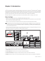
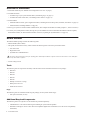
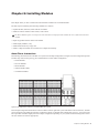
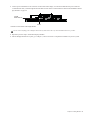
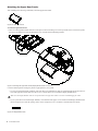
• Identify and organize the packages that make up your purchased system (see Figure 1) to simplify the assembly process. All required tools are in the Side Covers package (see “What’s Included” on page 2)
1
2
3
4
Figure 1. Packages organized before assembling an example S6 M10 16-5 system:
1 – Master Module Includes this guide and your M10 or M40 Master Module.
2 – Frame Components Chassis kits, Side Covers, Bolster, and Rear Panel packages.
3 – Power and Connectivity Power Supply Units (PSUs), Ethernet switch(es), Power Strip, and Cable Sets.
4 – Modules Automation, Fader, Process, Knob, and Display Modules (the number and type vary depending on configuration).
Chapter 1: Introduction 1
Overview of Installation
1
Determine module layout (“Modules and Configuration Overview” on page 5)
2
Assemble the frame
• Assemble Legs if your system includes them (“Assembling Legs” on page 13)
• Assemble the Frame Chassis kits (“Assembling Frame Chassis” on page 19)
3
Install modules
• Install the Ethernet switch, power supplies and cables (“Installing the Power Strip, PSUs, Switches, and Cables” on page 35)
• Install modules (“Installing Modules” on page 53)
4
Start up your system to confirm module communication, then complete the hardware assembly (Chapter 7, “How to Proceed”)
5
Activate your system purchase online, then log into your Avid Master Account to download and install S6 software updates,
Workstation installers, S6 documentation and other resources (“Updating S6 System Software” on page 67)
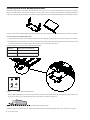
What’s Included
The Master Module package contains the following items:
• Master Module (M10 or M40)
• This guide (S6 Installation Guide), which contains the following items in the front pouch of the binder:
• Activation Card
• Registration Card
• System Restore USB Flash Drive
Do not use the System Restore drive for anything other than S6 System Restore software. Do not use this drive to store audio files
or any other data or software.
• Health & Safety Guide
Tools
The following tools are required for assembly of the S6 frame and are included in the Side Covers package:
• Hex M2.5
• Hex M3
• Hex M4
• Hex M5
• Hex M6
• Phillips screwdriver #1 (long)
• Phillip screw driver #2
• Small flat screw driver
Legs
The following tools are included with the Leg Set package (not all systems include Legs):
• One open end wrench (13 mm)
Additional Required Components
The following items are required to use S6 and must be purchased separately:
• USB Flash drive to use when transferring and installing S6 system software updates
• Workstation running Pro Tools or other EUCON-compatible digital audio workstation (see Avid.com for compatibility
information)
2
S6 Installation Guide
Optional
The following items are recommended and can be purchased separately:
• UPS (Uninterruptable Power Supply), power conditioner/timer, or other power management system
• USB computer keyboard and mouse/trackball (the Master Module provides a touchscreen keyboard, but you might prefer to
use a dedicated keyboard/mouse/trackball for some administrative or troubleshooting tasks)
System Requirements and Compatibility
Avid can only assure compatibility and provide support for hardware and software it has tested and approved.
For complete system requirements and a list of qualified computers, operating systems, hard drives, and third-party devices, visit:
www.avid.com/compatibility
Activation and Registration
Review the enclosed Activation Card and Registration Information Card and follow the instructions to Activate (required) and Register (optional, but highly recommended). These cards are located in the pouch at the front of this guide.
Activate S6 System Software Immediately
As soon as you have assembled your S6 system and confirmed a successful hardware installation, activate your S6 system software
on-line. Use the alphanumeric code on the included S6 System Software Activation Card to activate and download all S6 system
software and documentation.
Be sure to Activate your purchase using the enclosed Activation card so you can receive software updates directly in your Avid
account. Check your Avid account for system software updates, Workstation software, and XMON EUCON software
Registering
By registering, you become eligible to receive the following:
• Technical support information
• Software update and upgrade notices
• Hardware warranty information
Chapter 1: Introduction 3
About This Guide
This guide explains how to assemble your Avid S6 system.
Conventions Used in This Guide
All of our guides use the following conventions to indicate menu choices and key commands:
:
Convention
Action
File > Save
Choose Save from the File menu
Control+N
Hold down the Control key and press the N key
Control-click
Hold down the Control key and click the mouse button
Right-click
Click with the right mouse button
The names of Commands, Options, and Settings that appear on-screen are in a different font.
The names of switches and keys on the control surface are shown in bold (such as SEL).
The following symbols are used to highlight important information:
User Tips are helpful hints for getting the most from your system.
Important Notices include information that could affect your data or the performance of your system.
Shortcuts show you useful keyboard or mouse shortcuts.
Cross References point to related sections in this guide and other Avid guides.
About www.avid.com
The Avid website (www.avid.com) is your best online source for information to help you get the most out of your Avid system. The
following are just a few of the services and features available.
Product Registration and Activation Register your purchase online, and activate
Support and Downloads Contact Avid Customer Success (technical support); download software updates and the latest online
manuals; browse the Compatibility documents for system requirements; search the online Knowledge Base or join the worldwide
Avid community on the User Conference.
Training and Education Study on your own using courses available online or find out how you can learn in a classroom setting at
a certified Avid training center.
Products and Developers Learn about Avid products; download demo software or learn about our Development Partners and their
plug-ins, applications, and hardware.
News and Events Get the latest news from Avid or sign up for a product demo.
4
S6 Installation Guide
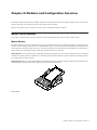
Chapter 2: Modules and Configuration Overview
This chapter identifies each of the S6 modules, and tells you how and where they can be arranged within a system. Use this information to determine your module layout before proceeding with the assembly.
There are two primary types of modules in a system, Master modules and Channel modules.
Master Section Modules
The S6 Master Module and S6 Automation Module are often installed in the same chassis to form a master section.
Master Module
The Master Module is the primary module of the system, providing the Touchscreen, two banks of Soft Keys, a monitoring section
and other controls. Each system must have one Master Module. There are two models of Master Module (M10 and M40) that are
used in S6 M10 or S6 M40 systems, respectively. They share identical controls and features, the only difference are the number of
other modules they each support, and the number of workstations that can be connected.
S6 M10 Systems These systems include an M10 Master Module that supports up to 10 other S6 modules, and up to two attached
workstations. S6 M10 systems accommodate 8 to 24 faders per frame and are suitable for smaller configurations. Display Modules
are not supported on S6 M10 systems.
S6 M40 Systems These system include an M40 Master Module that supports up to 40 S6 channel modules and up to 64 fader strips,
including Display Modules. M40 systems support up to eight attached workstations.
Master Module
Chapter 2: Modules and Configuration Overview 5
Automation Module
The Automation Module provides transport and locate controls, the Attention fader strip, Jog/Shuttle wheel, a numeric keypad, and
additional Soft Keys. The Automation Module is most often installed directly below and in the same chassis as the Master Module.
Automation Module
Channel Modules
Channel modules combine to form the fader strips of the system, and include the S6 Fader Module, S6 Process Module, S6 Knob
Module, and S6 Display Module. Not all configurations include each type of channel modules.
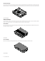
Fader Module
Each Fader Module provides eight channel faders with meters and other controls. Fader Modules are installed in the first slot of
each chassis (closest to the front).
Fader Module
Process Module
Each Process Module provides eight channel strips, each with a knob, OLED displays and other controls.
Process Module
6
S6 Installation Guide
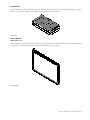
Knob Module
Each Knob Module provides eight channel strips, each with four dual-function (rotate/press) encoders, OLED displays, and other
controls. Up to two Knob Modules can be installed in the larger chassis M40 systems only.
Knob Module
Display Module
(M40 Systems Only)
Display Modules are supported on S6 M40 systems only, and are installed above channel modules. Each Display Module provides
a large display that shows names, meters, waveforms, and other data for up to eight strips.
Display Module
Chapter 2: Modules and Configuration Overview 7
Module Layout
This section describes the arrangements of modules front-to-back in their chassis, and chassis left-to-right in the frame.
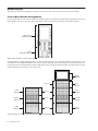
Front-to-Back Module Arrangements
In most configurations, master section modules are installed together in a single chassis with the Master Module above the Automation Module. They do not have to be in the same chassis, but for simplicity this guide shows them installed together.
Slots 2 and 3
Master Module
Slot 1
Automation Module
Master section modules in a Frame Chassis Small
Channel modules are usually installed together to provide the fader strips in a system. The Fader Module is installed in slot 1, Process Module in slot 2, and Knob Module in slot 3. Frame Chassis Small support one Knob Module per chassis; the Frame Chassis
Large support up to two Knob Modules per chassis. M40-based systems also support Display Modules. Not all slots need to contain
modules. Fill panels are available to cover unused slots.
Display
Module
Slot 4
Knob
Module
Knob
Module
Slot 3
Knob
Module
Process
Module
Slot 2
Process
Module
Fader
Module
Slot 1
Fader
Module
Channel modules in a Frame Chassis Small (left) and a Frame Chassis Large (right)
8
S6 Installation Guide
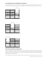
Left-to-Right Chassis and Module Arrangements
Channel sections and the master section modules can be arranged in any order, left-to-right. For example, in an S6 M10–16–5 system (16 faders with five knobs per strip) the master section modules can be located in three possible locations, as shown below.
Example 1: S6 M10-16-5 with master section at far right
Example 2: S6 M10-16-5 with master section in the center
Example 3: S6 M10-16-5 with master section at far left
About Custom Module Configurations
While several S6 systems are available in factory configurations that support standard module arrangements, you can customize the
arrangement of modules in many different ways. After you have assembled the system you will use the Touchscreen to tell the system where you have installed which modules; as you will see, there are many options for where you can place channel and master
section modules within different chassis.
For now, decide where you want your fader strips to be in relation to the master section modules, then proceed to Part II, “Frames.”
Chapter 2: Modules and Configuration Overview 9
10
S6 Installation Guide
Part II: Frames
Chapter 3: Assembling Legs
This chapter explains how to assemble the Leg Frames for the S6. Not all systems require Legs. If your system does not include
Leg Frames, please proceed to Chapter 4, “Assembling Frame Chassis.”
Make sure you have at least one other person available if you need to lift, turn, or move the system during and after assembly. Components and systems are heavy! Team lift, always.
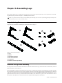
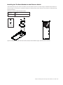
Unpack the Leg Frames
Unpack the Legs and Beams and identify the components shown in Figure 1.
1
3
5
4
2
Figure 1. Legs Frame components
1 – Legs
2 – Beams
3 – Beam Mounting Plates
4 – Back Corner Brackets
5 – End Shelves
6 – Fasteners and Tools (not shown)
Overview of Leg Frame Assembly
The Leg Frames consist of two Beams mounted across the back and front of the Legs and secured with Corner Brackets, Left and
Right End Shelves, and leveling feet.
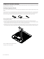
When assembling a Leg Frame as described in the next section, you should start by placing one of the Beams on the floor to gauge
how far apart the Legs need to be. Place the Legs parallel on the floor with proper spacing and put the first Beam across the back
of the Legs, orienting it as shown in the following diagrams and securing it with the Beam Mounting Plates and fasteners. Do not
tighten down fasteners all the way until both Beams and both Back Corner Brackets are in place. Once the back Beam is secured
then place the other Beam across the front and secure it with Beam Mounting Plates and fasteners.
Chapter 3: Assembling Legs 13
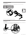
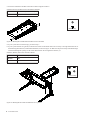
Attaching the Back Beam
Attaching the back Beam:
1
Place one of the Beams on the floor to determine how far apart the Legs need to be.
Have someone help hold the components while you position the Beams on the Legs and attach the fasteners.
2
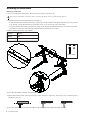
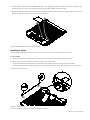
Attach the back beam by doing the following (see Figure 2):
• Put the first Beam across the back of the Legs. Align the pins on the underside of the Beams with the holes in the top of the
Legs. Be sure to orient the back Beam so that the pins on the top are closer to the center of the frame.
• Using four fasteners and washers (included) per mount, secure the Beam with Mounting Plates at each end. Do not tighten
down fasteners all the way until both beams and both Back Corner Brackets are in place.
Fasteners, Washers, and Tools for Legs to Beams
Fastener
M8x40
Washer
M8
Tool
M6 Hex
(Not to scale)
Figure 2. Attaching a Beam to the Legs using a Beam Mounting Plate
3
Make sure the Beam sits flat on the top of the legs as shown in Figure 3. If necessary, move the legs in or out until the proper
alignment is achieved.
Figure 3. Back view showing correct alignment of Beam on leg (at left), and incorrect alignment (middle, and right)
14
S6 Installation Guide
Attaching the Front Beam
To attach the front Beam:
1
Align the pins on the underside of the Beam with the holes in the top of the Legs. Be sure to orient the front Beam so that the
pins on the top are closer to the center of the frame.
2
Using four fasteners and washers (included) per mount, attach the Beam across the front of the Legs using two Beam Mounting
Plates as shown in Figure 4. Do not tighten the fasteners.
Fasteners, Washers, and Tools for Legs to Beams
Fastener
M8x40
Washer
M8
Tool
M6 Hex
(Not to scale)
Figure 4. Orientation of the pins on the top of the front beam
Chapter 3: Assembling Legs 15
Attaching the Back Corner Brackets
To attach the Back Corner Brackets:
1
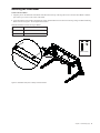
Attach the Back Corner Brackets as shown in Figure 5 using four fasteners and washers (included) per bracket. Align the pins
on the brackets with the holes in the top of the Legs.
Fasteners, Washers, and Tools for Back Corner Brackets
Fastener
M5x15
Washer
M5
Tool
M4 Hex
(Not to scale)
Figure 5. Attaching the Back Corner Brackets
2
16
Fully tighten all fasteners installed in the previous steps to completely secure the Beams and Back Corner Mounting Brackets
to the Legs. Check to make sure the Beams sit flat on the top of the legs.
S6 Installation Guide
Attaching the End Shelves
To attach the End Shelves:
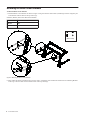
Using four fasteners and washers per side, attach the Left and Right End Shelves to the Legs as shown in Figure 6.
Fasteners, Washers, and Tools for End Shelves
Fastener
M5x15
Washer
M5
Tool
M4 Hex
(Not to scale)
Figure 6. Attaching the Left End Shelf (Right End Shelf shown attached)
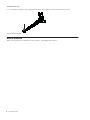
Leveling the Leg Frame
To level the back legs:
Use the 13 mm open end wrench (included with the Legs) and adjust the back leveling feet (see Figure 7). When looking down
at the feet from above, turn the wrench clockwise to raise or counterclockwise to lower.
Figure 7. Back Leg Leveler
Chapter 3: Assembling Legs 17
To level the front legs:
Use an M4 Hex to adjust the front leveling feet from above. Turn clockwise to raise, counterclockwise to lower.
Figure 8. Front leveling foot
How to Proceed
When your Leg Frames are assembled, proceed to Chapter 4, “Assembling Frame Chassis.”
18
S6 Installation Guide
Chapter 4: Assembling Frame Chassis
This chapter explains how to assemble the chassis and attach them to each other to form the frame of your S6 system.
As recommended in Chapter 1, identify all Frame component kits (Chassis kits, Side Covers, Bolster, and Rear Panel kits) as shown
in Figure 9.
Figure 9. Frame component packages for an example M10 16-5 system (left-to-right, Chassis Kits, Side Covers, Bolster, and Rear Panels)
Before You Begin
Do the following:
1
Open the Side Covers package and remove the included Frame Toolkit (labeled 7020-38627-00).
2
Locate and unpack all Frame Chassis components and place them near the work area.
3
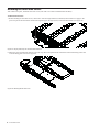
Identify each component (see Figure 10), then note whether your Frame Chassis are Large or Small. Some steps in the assembly
process vary depending the depth (Large or Small) of your Frame Chassis, as noted in these instructions.
Chapter 4: Assembling Frame Chassis 19
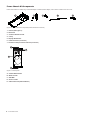
Frame Chassis Kit Components
Frame Chassis Kits are either Large (extended depth) or Small (reduced depth). The contents of both kits are the same.
1
2
3
Figure 10. Frame Chassis kit components (Cable Harnesses not shown)
1 – Chassis (See Figure 11)
2 – Back Foot
3 – Tie-down Bracket for PSU
4 – T-strip
5 – Display Module Filler
6 – Cable Harnesses (not shown)
7 – Fasteners: Phillips and Hex fasteners (not shown)
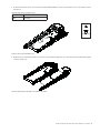
B
E
A
C
D
Figure 11. Chassis parts
A – Chassis Bottom Plate
B – Back Tie Plate
C – Side Wall
D – Front Tie Plate
E – Cable Harnesses (Ethernet/Power)
20
S6 Installation Guide
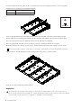
4
5
Assembling the Chassis
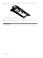
If you have not already done so, unpack all Frame Chassis and fasteners and arrange them next to each other on your work surface.
The Chassis kits also include tie-down brackets (for PSUs), a T-Strip, and Display Module Fillers. Set these aside for now.
Figure 12. Four Frame Chassis Small
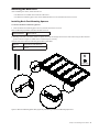
Attaching the End Side Wall
To attach the end Side Wall:
1
Open the S6 Side Covers package and unpack the included Side Wall.
Figure 13. End Side Wall
2
Attach the Side Wall to the Chassis Bottom Plate of the right-most chassis using three #1 Phillips screws. The right edge of the
Chassis Bottom Plate sits on top of the left edge of the Side Wall as shown in Figure 14.
Fasteners, and Tools for Chassis Bottom Plate to Side Wall
Fasteners
M3x6 SEMS (7760-30025-01)
Tool
#1 Phillips
(Not to scale)
Figure 14. Securing the end Side Wall to the Chassis Bottom Plate, top view (at left) and front view (lower right)
Chapter 4: Assembling Frame Chassis 21
3
Secure the Side Wall to the Back and Front Tie Plates using Hex fasteners.
Fasteners and Tools for Back and Front Tie Plates to Side Wall
Fasteners
M5x8 FHCS (7760-30553-00)
Tool
M3 Hex
(Not to scale)
Figure 15. Attaching the end Side Wall to the Back and Front Tie Plates
4
If your system does not include Legs, proceed to Step 6.
5
If your system includes a Leg Frame, mount the first chassis on the Beams and secure it loosely to the right end shelf from underneath using Hex fasteners (included with the Beams) as shown in Figure 16. Make sure the pins on the top of the Beams align
with and fit through the openings in the Chassis Bottom Plate. Do not tighten the fasteners yet.
Fasteners, Washers, and Tools for Chassis to Beams
Fasteners
M6x14 Hex (SHCS)
Washers
M6
Tool
M5 Hex
(Not to scale)
Figure 16. Attaching the first chassis to the Beams of a Leg Frame
22
S6 Installation Guide
6
Move the next chassis into position so that the right edge of its Chassis Bottom Plate sits on top of the left edge of the first chassis
as shown in Figure 17.
Figure 17. Attaching the first two chassis (top view, at left, and front view, at right)
7
If your system includes a Leg Frame, attach the second chassis to the Beams and secure loosely using more of the Hex fasteners
included with the Beams as shown in Figure 16. Tighten them enough to hold the chassis in place, but do not tighten them fully.
8
Attach the right edge of the second chassis Bottom Plate to the left edge of the Side Wall of the first chassis using three #1 Phillips screws as shown in Figure 18. Do not tighten the screws fully.
Fasteners, and Tools for Chassis Bottom Plate to Side Wall
Fasteners
M3x6 SEMS (7760-30025-01)
Tool
#1 Phillips
(Not to scale)
Figure 18. Securing the Chassis Bottom Plate of the first chassis to the Side Wall of the second chassis
Chapter 4: Assembling Frame Chassis 23
Secure the Back and Front Tie plates of the second chassis to the first chassis using Hex fasteners as shown in Figure 19.
9
Fasteners and Tools for Back and Front Tie Plates to Side Wall
Fasteners
M5x8 FHCS (7760-30553-00)
Tool
M3 Hex
(Not to scale)
Figure 19. Securing the Back and Front Tie Plates of the first chassis to the Side Wall of the second chassis (cables not shown)
10
Fully tighten all screws holding the Side Walls to the Chassis Bottom Plate (Phillips), Back and Front Tie Plates (Hex).
11
If your system includes legs, fully tighten the fasteners securing each chassis to the Beams.
12
If you are assembling an 8-fader system (two chassis), proceed to “Attaching the Back Feet” on page 25.
13 All
other configurations, repeat the previous steps to assemble all Frame Chassis kits, then continue to the next section.
If your system includes a Producer’s Desk option, see the Producer’s Desk Guide for assembly and installation instructions.
Figure 20 shows an example illustration of four assembled Frame Chassis Large (a 24-fader system).
Figure 20. Four Frame Chassis Large (cables not shown)
Important
Do not lift or move an S6 desktop system that is five or more chassis in width (32-faders or more). If you need to move a
five-or-wider S6 system that does not include Legs, you must partially disassemble the frame so that no section is more than four
chassis in width. For more information, see Appendix A, “Expanding or Disassembling S6.”
24
S6 Installation Guide
Attaching the Back Feet
After assembling the chassis, attach the back feet.
• One Back Foot is included with each Frame Chassis Kit.
• Two Back Foot Mounting Spacer bars and an additional Back Foot are included in the Side Covers kit.
Installing Back Foot Mounting Spacers
To install the two Back Foot Mounting Spacers:
1
Locate the Back Foot Mounting Spacer bars (2) included in the Side Covers kit.
Back Foot Mounting Spacer Bars included in the Side Covers kit
Back Foot Spacers
2
7600-31390-00
Standing at the back of the frame, attach one Spacer bar to the left and right back corners of the frame using two Hex fasteners
per bar as shown in Figure 21. Make sure to orient the Spacers correctly.
Fasteners and Tools for Book Foot Mounting Spacer Bars to Side Walls
Fasteners
M5x8 FHCS (7760-30553-00)
Tool
M3 Hex
(Not to scale)
Figure 21. Back Foot Mounting Spacer Bars (upper left), and attaching the Back Foot Mounting Spacer bars
Chapter 4: Assembling Frame Chassis 25
Attaching the Back Feet
To attach the Back Feet:
1
Unpack each Back Foot and screws from each Frame Chassis kit. Locate and unpack the additional Back Foot in the Side Covers
package.
Back Feet
Back Feet and
Fasteners
7020-38616-00
Back Foot, Mounting Bracket, and screws
The number of back feet is equal to the number of chassis (width) of the frame, plus one. For example, a 16-fader S6 system has
a frame width of three chassis, so it requires four back feet (3+1=4). Similarly, a 32-fader system requires six back feet (5+1=6).
2
Using a #2 Phillips screwdriver (magnetic tip recommended) and included #2 Phillips screws, attach the assembled feet to the
back of the frame. Be sure to orient them correctly before securing them to the frame.
Fasteners and Tools for Back Foot Mounting Bracket to chassis
Fasteners
M5x12 (7760-30554-00)
• At the left- and right-most ends of the frame, attach the feet to the Spacer bars and adjacent Back Tie Plates as shown in
Figure 22.
(Not to scale)
Figure 22. Attaching a Back Foot at one end of the back of the frame
If the threaded foot blocks access to the mounting screws extend the foot a few turns. See “Leveling the Chassis” on page 27.
26
S6 Installation Guide
• All other Back Feet are mounted to adjacent Back Tie Plates as shown in Figure 23.
Figure 23. Attaching a Back Foot to two adjacent Back Tie Plates
Leveling the Chassis
After the feet are mounted to the frame, check that the chassis is level. If one or more feet are too short or too tall, raise or lower
them in order to level and support the back of the frame. You can adjust the feet using an M3 hex driver as shown in Figure 24
Figure 24. Leveling the back feet
Chapter 4: Assembling Frame Chassis 27
Attaching the Bolster
The Bolster is a one-piece reinforced arm rest that matches the width of your configuration. The wide, padded surface provides a
comfortable work area, and its one-piece design provides additional structural support along the front of the control surface.
The Bolster hangs along the front edge of the frame and is secured from below using fasteners.
To attach the Bolster:
1
Locate the Bolster and remove it from its packaging, being careful to locate the included fasteners.
2
Note the power cables included in the Bolster package. These are for the PSUs and Ethernet switch and will be installed later.
Set them aside for now.
3
Pick up the Bolster using both hands. When installing larger systems (6 or more chassis in width), get someone to help.
4
Make sure the Bolster is oriented correctly and carefully lower it onto the receiving edge along the top of the front edge of the
frame, so the Bolster hangs in position as shown in Figure 25.
5
Attach the Bolster to the frame from below by partially threading all the included Hex fasteners. Do not fully tighten the fasteners yet.
6
After all fasteners are in place, return to the first fastener and tighten it and the others securely.
Fasteners and Tools for the Bolster
Fasteners
M5x10 BHCS (7760-30615-00)
Tool
M3 Hex
(Not to scale)
Figure 25. Attaching the Bolster
Never attempt to move or lift a chassis (any size) by the Bolster, Side Covers or Rear Panels (they can break). Move or lift while
holding on to the metal chassis (frame) instead.
28
S6 Installation Guide
Installing Display Module Mounting Brackets
If your system includes Display Modules, install their mounting brackets as explained in the following instructions. (The Display
Modules are attached to the mounting brackets later.)
If your system does not include Display Modules, proceed to “Installing Rear Panel Mounting Brackets” on page 30.
If your system includes one or more Display Modules, do the following:
1
Unpack all S6 Display Modules and locate their mounting brackets. Fasteners are included in a small bag taped to the bracket.
Use the four flathead Hex fasteners to attach the brackets to the chassis. Set the other four rounded fasteners aside (these will be
used to attach the module to the brackets later).
2
Attach the first Display Module Mounting Bracket to the four holes located on the center of each channel chassis’ Back Tie Plate
using four flathead Hex fasteners. Be sure to orient the brackets correctly, as shown in Figure 26. Do not attach a Display Module
Mounting Bracket to the chassis that will contain your master section modules.
Fasteners and Tools for the Display Module Mounting Brackets
Fasteners
M5x12 FHCS
Tool
M3 Hex
(Not to scale)
Figure 26. Attaching Display Module Mounting Brackets
3
Repeat for other Display Modules, attaching their brackets to the back of each channel chassis.
4
Leave the actual Display Modules aside for now. You will attach them to the mounting brackets later.
Chapter 4: Assembling Frame Chassis 29
Installing Rear Panel Mounting Brackets
Rear Panels support and conceal cables. Rear Panels consist of two pieces, a lower bracket that mounts to the frame, and an upper,
hinged cover that attaches to the bracket. The upper covers have open corners to guide power and Ethernet for Display Modules (if
your system includes Display Modules), and cutouts to support S6 Options (such as the Speaker Bridge and VESA Monitor mount).
Figure 27. Rear Panel Lower Mounting Bracket (left) and Upper Cover (right). Fasteners, Display Module Fillers, and cutouts not shown.
To install the Rear Panel Mounting Brackets:
1
Unpack the Rear Panel lower bracket and its fasteners from their packaging (each bracket uses two Hex fasteners and washers).
2
Standing at the back of the frame, start at the far left and attach one Rear Panel bracket to the Back Tie Plates of the first two chassis using Hex fasteners and washers. Figure 28 shows how they are attached to the chassis.
Fasteners, Washers, and Tools for Rear Panel Mounting Brackets
Fasteners
M5x8 SHCS (7760-30593-00)
Washers
M5 WSHR
Tool
M4 Hex
(Not to scale)
Figure 28. Attaching Rear Panel Mounting Brackets
Before tightening the fasteners, make sure the bottom lip of the tray is flat against the lower back edge of the chassis (make sure
the lip is not sitting on, or hooked below, the edge of the chassis) as shown in Figure 29.
Figure 29. Side view showing proper alignment of Rear Panel to back of chassis
3
30
Set the Upper Covers aside for now. These are attached to the Lower Mounting Brackets later, after cable runs are in place.
S6 Installation Guide
Installing Side Covers
Side Covers (one Left, and one Right) consist of two pieces: a mounting plate that attaches to the frame, and an outer panel that attaches to the mounting plate and secured from inside the chassis.
Attaching the Side Mounting Plates
To attach the Side Mounting Plates:
1
Unpack the Side Covers package and identify the Left and Right Side Mounting Plates and their fasteners.
2
Secure the Left Side Mounting Plate to the left side of the frame using the included (rounded) Phillips screws, making sure to
orient the brackets correctly as shown in Figure 30.
Fasteners and Tools for the Side Mounting Plate
Fasteners
M4x14 SEMS (7760-30610-00)
Tool
#2 Phillips
(Not to scale)
Figure 30. Attaching the left side panel mounting plates
3
Secure the Right Side Mounting Plate to the right side of the frame, making sure to orient them correctly as shown in Figure 31.
Figure 31. Attaching the right side panel mounting plates
4
Set the outer Side Covers aside for now. You will install them later, after cabling is in place.
Chapter 4: Assembling Frame Chassis 31
How to Proceed
After assembling the chassis that form your system frame, proceed to Chapter 5, “Installing the Power Strip, PSUs, Switches, and
Cables.”
32
S6 Installation Guide
Part III: Modules
Chapter 5: Installing the Power Strip, PSUs, Switches,
and Cables
This chapter explains how and where to install the Power Strip, Ethernet switches and Power Supply Units (PSUs), how to connect
Ethernet throughout the system using the included Cable Sets, and how to connect power to PSUs and the switch.
As recommended in Chapter 1, identify and organize the packages containing the Power Strip, Ethernet switch(es), PSUs, and Cable Sets.
Figure 1. Packages for electrical components (left-to-right, Power Supplies, Ethernet switch, Power Strip (PDU), and Cable Sets). Type and
number of packages varies depending on configuration
Overview
The basic steps are:
1
Install the Power Strip (see “Installing the Power Strip” on page 36).
2
Determine switch and PSU placement for your configuration as described in “Ethernet Switch and PSU Placement per System
Configuration” on page 37.
3
Place the Ethernet switch in the appropriate chassis (see “Installing the Ethernet Switch” on page 40).
4
Place PSUs in the appropriate chassis (see “Installing PSUs” on page 41) and secure them using the included tie-down brackets.
5
Attach the special AC power cables (included) to the Ethernet switch and PSUs (see “Installing the Ethernet Switch” on
page 40). Do not connect power cables to the Power Strip yet.
6
Install Cable Sets to connect the Ethernet switch(es) to each chassis, then install the single Ethernet cable for workstations (see
“Installing and Connecting Cabling” on page 44).
7
After all Ethernet cables are in place, connect the AC cables for the switch and PSUs to the power strip.
8
Install the Ethernet switch tie-down bracket to secure it to the chassis.
Chapter 5: Installing the Power Strip, PSUs, Switches, and Cables 35
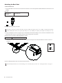
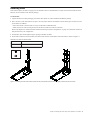
Installing the Power Strip
The power strip is placed across the Rear Panel brackets, behind the center of the frame.
To install the power strip:
1
Standing behind the middle of the frame, place the power strip on the Rear Panel brackets so that it sits on the angled arms of
the brackets as shown in Figure 2. The power strip’s sockets should face up and towards the front of the frame.
.
(Not to scale)
Figure 2. Power strip placement on Rear Panel brackets (back view at left, side view at right)
2
36
Take the power strip’s AC cable and run it along the back of the frame to the far left or right end. Do not connect to power outlet
yet.
S6 Installation Guide
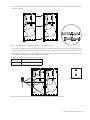
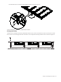
Ethernet Switch and PSU Placement per System Configuration
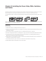
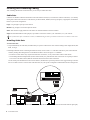
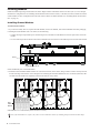
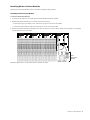
Figure 3 illustrates switch and PSU placement for an example 32-fader (five chassis wide) system.
When determining the placement of the Ethernet switch, observe the following guidelines based on your configuration and frame
depth.
• When assembling an Extended Depth Frame (Frame Chassis Large), install the Ethernet switch in the chassis in the middle,
or next to the middle of the frame as shown in the diagrams on the following pages.
• When assembling a Reduced Depth Frame (Frame Chassis Small) the Ethernet switch must go in the same chassis as the master section modules. Depending on where you place your Master section (left-to-right) in the frame, the diagrams showing
switch and PSU placement may not be appropriate for Reduced Depth Frame systems. Just be sure to install the Ethernet
switch in the same chassis as your master section modules, then follow the other guidelines to determine where to install
PSUs. Cable Sets of sufficient length are included with all systems to make connections between the switch and all chassis.
• Install one PSU in each chassis but do not place one in the same chassis as the Ethernet switch. Instead, put two PSUs in an
adjacent chassis.
Figure 3. Placement of PSUs, Ethernet switch and tie-down brackets for an example 32-fader system (cables not shown)
The diagrams on the following pages show where to put PSUs and the Ethernet switch(es) in Avid-configured and custom
configurations.
If your system includes a Producer’s Desk option, see the Producer’s Desk Guide for switch, PSU, and cabling instructions.
Chapter 5: Installing the Power Strip, PSUs, Switches, and Cables 37
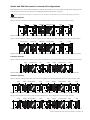
Switch and PSU Placement for Avid-Configured S6 Systems
These diagrams show switch and PSU placement for all frame widths available with Avid-configured S6 systems, which range in
size from 8-fader/two chassis (such as an S6 M10-8-5) up to 32-fader/five chassis (such as an M40-32-9-D). For larger (custom)
configurations see Chapter 5, “Installing the Power Strip, PSUs, Switches, and Cables”.
You will first place the units in their chassis, then connect their power cables. After units are installed, proceed to “Installing the
Ethernet Switch” on page 40.
When assembling a Reduced Depth Frame (Frame Chassis Small) the Ethernet switch must go in the same chassis as the master
section modules. Depending on where you place your Master section (left-to-right) in the frame, the diagrams showing switch and
PSU placement may not be appropriate for Reduced Depth Frame systems. Just be sure to install the Ethernet switch in the same
chassis as your master section modules, then follow the other guidelines to determine where to install PSUs. Cable Sets of sufficient length are included with all systems to make connections between the switch and all chassis.
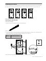
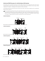
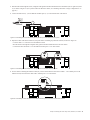
2–Chassis Systems
PSUs (2)
Ethernet switch
Ethernet switch and PSU placement for an two-chassis, 8-fader system (cables not shown)
3–Chassis Systems
PSUs (2)
Ethernet switch
PSU
Ethernet switch and PSU placement for a three-chassis, 16-fader system (cables not shown)
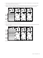
4–Chassis Systems
PSU
PSUs (2)
PSU
Ethernet switch
Ethernet switch and PSU placement for a four-chassis, 24-fader system (cables not shown)
5–Chassis Systems
PSU
PSUs (2)
Ethernet switch
PSU
PSU
Ethernet switch and PSU placement for an example five-chassis, 32-fader system (cables not shown)
38
S6 Installation Guide
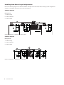
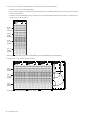
Switch and PSU Placement for Custom S6 Configurations
These diagrams show switch and PSU placement for example systems that are six or more chassis in width. Install and secure units
as shown for your frame size, then proceed to “Installing and Connecting Cabling” on page 44.
If your system includes a Producer’s Desk option, see the Producer’s Desk Guide for switch, PSU, and cabling instructions.
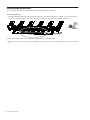
6-Chassis Systems
Figure 4 shows an example six-chassis system such as an M40-40-5 that requires a single 24-port Ethernet switch.
PSU
PSU
PSUs (2)
Ethernet switch
PSU
PSU
Figure 4. Ethernet switch and PSUs in a 40-fader system requiring one switch
Figure 5 shows a different example six-chassis system such as an M40-40-9-D. This configuration uses two Ethernet switches.
16-port switch
PSUs (2)
PSUs (2)
24-port switch
PSU
PSU
Figure 5. Ethernet switches and PSUs in a 40-fader system with two switches, a 16-port in chassis 1 (far left) and a 24-port in chassis 4
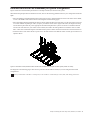
7-Chassis Systems
Figure 6 shows an example seven-chassis system such as an M40-48-9-D. This configuration uses one 16- and one 24-port switch.
PSUs
16-port switch
PSU
PSU
PSUs
24-port switch
PSU
Figure 6. Ethernet switches and PSUs in a 48-fader system requiring two switches, a 16-port in chassis 2 and a 24-port in chassis 6
9-Chassis Systems
Figure 7 shows an example nine-chassis system such as an M40-64-9. This configuration uses one 16- and one 24-port switch.
PSU
PSUs
16-port switch
PSU
PSU
PSUs
24-port switch
PSU
PSU
Figure 7. Ethernet switches and PSUs in a 64-fader system requiring two switches, a 16-port in chassis 3 and a 24-port in chassis 7
Figure 8 shows another nine-chassis system such as an M40-64-9-D. This configuration uses two 24-port switches.
PSU
PSUs
24-port switch
PSU
PSU
PSUs
24-port switch
PSU
PSU
Figure 8. Ethernet switch and PSU placement for a 64-fader system with two 24-port switches, one in chassis 3 and the other in chassis 7
Chapter 5: Installing the Power Strip, PSUs, Switches, and Cables 39
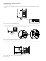
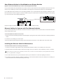
Installing the Ethernet Switch
The capacity (number of ports) and number of switches in your system depends on the number of chassis and module in your systems. Systems with fewer chassis and modules might only require a single 16-port switch, larger systems a 24-port switch, while
the largest systems (23 or more modules) require two Ethernet switches. Ethernet switches are installed into specific chassis and
secured with the included tie-down bracket.
If your system includes a Producer’s Desk option, see the Producer’s Desk Guide for switch, PSU, and cabling instructions.
To install the Ethernet switch(es):
1
Unpack the Ethernet switch(es), the included Ethernet cables and tie-down bracket with fasteners. Although the switch includes
a standard power cable in the Ethernet Switch box, you must use one of the additional power cables (C14 type) included in the
Bolster package.
Do not use the power cable provided in the Ethernet switch box (it has a standard male IEC connector which will not work with
the S6 Power Strip).
2
Attach the included feet to the bottom of the Ethernet switch. (Very important!)
3
Refer to the diagrams in “Ethernet Switch and PSU Placement per System Configuration” on page 37 to determine switch and
PSU placement for your configuration.
4
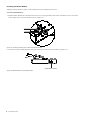
After determining placement for your configuration, install the Ethernet switch(es) in the appropriate chassis by doing the following
• If necessary, disconnect the power harness from the terminal port on the inside of the Back Tie Plate (see Figure 9).
Figure 9. Power harness (make sure it is disconnected before installing Ethernet switch)
• Place the switch in the chassis so that its ports face the back of the frame (the ports should be visible through the horizontal
opening in the Back Tie Plate as shown in Figure 10).
Figure 10. Back view of a chassis with an Ethernet switch
Connecting Power to the Ethernet Switch
To connect power to the Ethernet switch:
1
Take the male AC power cable provided with the Ethernet switch(es), disconnect it from the switch and set it aside.
2
Locate the additional AC (C14) power cable included in the Bolsters package.
3
Feed the switch end through the opening of the Back Tie Plate and connect it to the Ethernet switch(es).
• If you are assembling a Frame Chassis Small, the power cable needs to be placed underneath the switch (it is a tight fit).
4
Connect the other end to the power strip you installed at the beginning of this chapter.
5
If your system includes two Ethernet switches, repeat for the other switch.
6
Set the tie-down bracket aside (it is installed after all cables are in place).
40
S6 Installation Guide
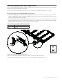
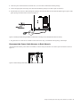
Installing PSUs
Each chassis requires one PSU to supply power for modules. PSUs are installed alone or in pairs and secured with the tie-down
brackets (one is included in each Chassis package).
To install PSUs:
1
Unpack all PSUs from their packaging, and collect their special AC cables included in the Bolster package.
2
Place one PSU in each chassis but do not place one in the same chassis as the Ethernet switch. Instead, put two PSUs in an adjacent chassis. In addition:
• Place PSUs under or between (but not on top of) the built-in Cable Harnesses.
• Make sure the DC cable is facing the front of the frame, and the AC socket is to the back.
Refer to the diagrams in “Ethernet Switch and PSU Placement per System Configuration” on page 37 to determine switch and
PSU placement for your configuration.
3
Feed the DC cable out through the largest opening in the Back Tie Plate.
4
Secure PSUs with the tie-down brackets (one bracket with fasteners is included in each Chassis kit) as shown in Figure 11.
Fasteners, and Tools for PSU tie-downs
Fasteners
M3x6 SEMS
Tool
#1 Phillips
Figure 11. Installing one PSU and tie-down (shown at left) and two PSUs and tie-downs (at right). Cables and wall not shown.
Chapter 5: Installing the Power Strip, PSUs, Switches, and Cables 41
Connecting Power Cables to the PSUs
To connect power to PSUs:
1
If you haven’t already, feed the DC power cable from each PSU out through the opening in the Back Tie Plate as shown in
Figure 12.
Figure 12. Power cable terminal through the Back Tie Plate
2
Connect the cable terminal end from the outside back of the chassis to the power terminal connector on the Back Tie Plate as
shown in Figure 13. Use a small flathead screwdriver to secure the plug to the terminal.
Figure 13. Connecting the cable terminal at the Back Tie Plate
3
Do the following to connect power to the chassis containing the Ethernet switch (see Figure 14):
• In the chassis with two PSUs, feed the DC cable of the second PSU through the largest opening in the Back Tie Plate, then run
the cable across to the chassis with the switch.
• Attach the terminal end to the power terminal connector on the Back Tie Plate of that chassis and secure it with a flathead
screwdriver.
Figure 14. Routing power cables to a chassis with an Ethernet switch
42
S6 Installation Guide
4
Locate the power cables included in each PSU box, as well as those included in the Bolster package.
5
Connect the appropriate end of the power cables from the Bolster package to the PSU (repeat for all PSUs).
6
Feed the other end of the AC cables through the opening in each Back Tie Plate and run them through the upper (square) cable
guide openings in the Rear Panel as shown in Figure 15.
Figure 15. Feeding the cable through the Back Tie Plate and connecting it to the PSU (Ethernet switch not shown)
7
Plug each PSUs AC cable into an available socket on the Power Strip you installed at the beginning of this chapter.
Reconnect the Power Cable Harness to Each Chassis
After all Ethernet and PSU power cables are installed, reconnect each power harness to its chassis power terminals as shown in
Figure 16.
Figure 16. Reconnecting Power harness (switch and PSUs not shown)
Chapter 5: Installing the Power Strip, PSUs, Switches, and Cables 43
Installing and Connecting Cabling
After installing the Ethernet switch and PSUs you are ready to install Cable Sets.
Cable Sets
Cable Sets are bundles of Ethernet cables that connect the Ethernet switch(es) to each chassis. Cables are labeled (1–5) to identify
and organize cables and connections. Cable Sets are provided in Small, Medium, and Large (lengths), in appropriate combinations
based on your frame configuration.
Large Long enough to span up to three chassis.
Medium Long enough to reach to the adjacent chassis.
Small Short cables to supply Ethernet to the chassis in which the Ethernet switch is installed.
Single An individual Ethernet cable (purple) is provided to connect the switch to your workstation, or to your network.
For systems that require two Ethernet switches, an additional single cable is provided to connect the two switches to each other.
Installing Cable Sets
To install Cable Sets:
1
Unpack and identify all Cable Set(s) included with your system. Cable Sets are color coded according to their length (Small, Medium, or Large).
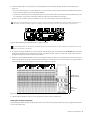
2
Standing behind the chassis containing the Ethernet switch, connect cables 1–5 of the first Cable Set to ports on the Ethernet
switch by feeding them through the slot in the Back Tie Plate as shown in Figure 17. In addition:
• The master section chassis only requires three Ethernet connections, so only connect three cables to that chassis.
• If assembling a Reduced Depth Frame (Frame Chassis Small), only four Ethernet cable connections are required per chassis.
You can leave this fifth (unused) Ethernet cable disconnected from the switch and chassis.
Use the switch ports that make the most sense for distance, identification or personal preference. We suggest starting on the bottom row to make it easier to connect other Cable Sets later, but your specific configuration will determine the best arrangement.
1
2
3
4
5
1
2
3
4
5
1
2
3
4
5
Figure 17. Connecting the first Cable Set to the Ethernet switch (top view shown at lower left; back view of chassis shown at upper right)
44
S6 Installation Guide
3
Run the Cable Set through the (lower) triangular cable guides in the Rear Panel brackets to the furthest (left- or right-most) chassis, as shown in Figure 18. (For systems with more than three chassis, see “Installing Cable Sets in Large Configurations” on
page 46.)
4
Connect the other ends (1–5) to the Ethernet terminal ports (1–5) on the outside back of the chassis
1
2
3
4
5
11
22
33
44
55
1
2
3
4
5
Figure 18. Connecting the first Cable Set to the first (left-most) chassis Ethernet terminal ports
5
Repeat for other Cable Sets and chassis (except the chassis containing any Ethernet switches) as shown in Figure 19:
• Connect cables 1–5 of the next set to the Ethernet switch.
• Run the cable set through the triangular cable guides in the Rear Panel Mounts to the next chassis.
• Connect the Cable Set cables 1–5 to the Ethernet terminal ports 1–5 on each chassis.
1
2
3
4
5
11
22
33
44
55
1
2
3
4
5
Figure 19. Connecting the next Cable Set to the right-most chassis Ethernet terminal ports
6
For the chassis containing the Ethernet switch(es), use the Small Cable Set and connect cables 1–5 to available ports on the
Ethernet switch, and connect the other ends to terminal ports 1–5 on the chassis.
1
2
3
4
5
1
1
2
2
3
3
4
4
5
5
1
2
3
4
5
Figure 20. Connecting a Cable Set Small to the Ethernet terminal ports on the back of the switch chassis
Chapter 5: Installing the Power Strip, PSUs, Switches, and Cables 45
Installing Cable Sets in Large Configurations
Refer to the following diagrams for Cable Set installation examples for four-chassis (24-fader) and larger system configurations.
Numbers in the diagram indicate the type of Cable Set installation.
4-Chassis Systems
(See Figure 21):
1
Cable Set Large
2
Cable Set Medium
3
Cable Set Small
3
1
1
2
3
4
5
2
1
2
3
4
2
5
1
2
3
4
1
5
Figure 21. Cable Sets in a 24-fader (four chassis) system.
5-Chassis Systems
(See Figure 22):
1
Cable Set Large
2
Cable Set Medium
3
Cable Set Small
3
1
2
Figure 22. Cable Sets in a 32-fader (five chassis) system
46
S6 Installation Guide
2
1
2
3
4
5
6-Chassis Systems
Systems with 40 faders (six chassis) require slightly different cabling depending on the number of modules in the system (which
determines whether the system needs one or two Ethernet switches).
Example 1 (Single Ethernet Switch: see Figure 23):
1
Cable Set Large
2
Cable Set Medium
3
Cable Set Small
3
1
1
2
2
1
Figure 23. Example 1: Cable Sets in a 40-fader (six chassis) system with a single Ethernet switch
Example 2 (Dual Ethernet Switches: see Figure 24):
1
Cable Set Large
2
Cable Set Medium
3
Cable Set Small
4
Ethernet Cable (single) to connect the two switches to each other
4
3
3
1
2
1
2
Figure 24. Example 2: Cable Sets in a 40-fader (six chassis) system with two Ethernet switches
7- and 9-Chassis Systems
For systems with seven or more chassis, use the previous diagrams and order of connections to install Cable Sets. For example, if
you are assembling a 7-chassis system connect the Ethernet switches to each other first using the single, long Ethernet cable, then
use Large and Medium Cable Sets to connect each switch to its surrounding chassis, following the examples above.
Chapter 5: Installing the Power Strip, PSUs, Switches, and Cables 47
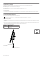
Short Ethernet Cables for Knob Modules and Display Modules
(Systems with Two Knob Modules per Chassis and/or Display Modules Only)
If your system includes two Knob Modules in any chassis, take one of the included 12-inch long Ethernet cables and connect one
end of it to an available port on the interior of the Back Tie Plate. Repeat for all chassis that will have two Knob Modules.
If your M40-based system includes one or more Display Modules, route a 12-inch Ethernet cable through the middle hole on the
back of the chassis as shown in Figure 25. Feed an available 2-pin power cable from the Cable Harness through the same opening
(you will connect these to the Display Module later).
Figure 25. routing a short Ethernet cable for a Display Module (2-pin power cable not shown)
Ethernet Cabling for Systems with Two Ethernet Switches
If your system includes 23 or more modules, two Ethernet switches are required. The two switches must be connected to each other
using a single Ethernet cable.
To connect two Ethernet switches to each other:
1
Feed one end of the included single Ethernet cable through the opening in the back of either of the chassis containing an Ethernet
switch.
2
Connect it to an available port on the switch.
3
Run the cable through the triangular openings in the Rear Panels and connect it to an available port on the other switch.
Installing the Ethernet Cable for Workstations
To install an Ethernet cable for connecting to workstations:
1
Connect one end of the single Ethernet cable (included with the Ethernet switch) to an available port on the switch.
2
Guide the cable across the Rear Panels to the far left-or-right. Do not yet connect it to any workstations, routers, or switches.
Do not connect the system to any workstation, external routers, switches or networks until after you have updated S6 system software as explained later in this guide.
3
Leave it disconnected for now (you will attach this cable to your workstation or router after updating S6 software).
4
If you plan on connecting directly to multiple workstations, connect another Ethernet cable (not included) to an available port
on the switch and route it as described in the previous steps.
48
S6 Installation Guide
Installing the Tie-Down Bracket for the Ethernet Switch
After all Ethernet and power cables are installed, secure the Ethernet switch to its chassis using its included tie-down bracket as
shown in Figure 26. The bracket is included in the Ethernet Switch package, and its fasteners are provided in a small plastic bag
taped to the bracket.
Fasteners, and Tools for Ethernet switch tie-downs
Fasteners
M3x6
Tool
#1 Phillips
(Not to scale)
Figure 26. Installing an Ethernet switch and tie-down (at left) and after installation (right). Cable Harnesses not shown.
Chapter 5: Installing the Power Strip, PSUs, Switches, and Cables 49
Attaching the Outer Side Covers
After cables are in place, install the outer side covers (outer side covers must be installed before modules).
To attach the Side Covers:
1
Before attaching the outer Side Covers, make sure to route the single Ethernet (workstation) cable and the AC supply to the
power strip across the Rear Panels and down through the gap to the right (or left) of the outer Rear Panels (see Figure 27).
Figure 27. Gap for power strip AC and workstation Ethernet
2
Make sure power and Ethernet cables are not in the way, then set the panel into the side bracket so that its tabs hang on the slots
on the mounting plate as shown in Figure 28.
Figure 28. Attaching the left Side Cover
50
S6 Installation Guide
3
From the inside of the chassis, use four of the included flathead Phillips screws to secure the Side Cover to the frame as shown
in Figure 29.
Fasteners and Tools for the Side Covers
Fasteners
M4x14 FHPH
Tool
#2 Phillips
(Not to scale)
Figure 29. Securing the left Side Cover
4
Make sure power and Ethernet cables are not in the way, then take the right Side Cover and attach it to the right mounting plate
as shown in Figure 30.
Figure 30. Attaching the right Side Cover (Bolster not shown)
Chapter 5: Installing the Power Strip, PSUs, Switches, and Cables 51
5
From the inside of the chassis, use four more flathead Phillips screws to secure the right Side Cover to the frame as shown in
Figure 30.
Figure 31. Attaching the right Side Cover (Bolster not shown)
Never attempt to move or lift a chassis (any size) by the Side Covers, Bolster, or Rear Panels (they can break). Move or lift while
holding on to the metal chassis (frame) instead.
How to Proceed
After assembling the frame and installing the Ethernet switch, PSUs and cabling, proceed to Chapter 6, “Installing Modules.”
52
S6 Installation Guide
Chapter 6: Installing Modules
This chapter shows you how to install and connect hardware modules into an assembled frame.
The basic steps for installing and connecting modules are as follows:
• Populate the first (left-most) chassis with all its modules.
• Install and connect modules in each chassis, front-to-back.
The Master Module requires several special connections that are unique from other modules. Be sure to follow all instructions
carefully.
• Repeat to populate all other chassis with modules.
• Install Display Modules, if any.
• Install Fill Panels into any empty slots.
• Install a Compression Panel into each chassis to complete the assembly.
About These Instructions
The following instructions show an S6 M40–24–5 system as an example configuration (see Figure 32). This configuration provides
24 fader strips with 5 knobs per strip, plus a standard master section module configuration.
• 3 Fader Modules
• 3 Process Modules
• 3 Knob Modules
• 1 Master Module (M40)
• 1 Automation Module
Figure 32. Arrangement of modules in example S6 M40 24-5 system
This example configuration has the master section modules at the far right of the system with faders to the left. However, modules
can be arranged in many different positions as explained in Chapter 2, “Modules and Configuration Overview.” Your exact installation procedure will differ slightly from this example configuration depending on your system and desired arrangement of modules (all variations are noted as appropriate).
Chapter 6: Installing Modules 53
Installing Modules
Install all modules beginning with the left-most chassis. Begin with the slot/module closest to the front (slot 1). In our example
S6 M40 24-5 configuration we are installing channel modules in the left-most chassis, so the first (front-most) module to install is
a Fader Module. In other configurations the left-most chassis could be for Master modules (see “Installing Master Section Modules” on page 57).
Installing Channel Modules
To install Channel modules:
1
2
If you haven’t already done so, unpack one Fader Module, one Process Module, and one Knob Module from their packaging.
Holding the Fader Module close to its chassis, do the following:
• Connect the longest 2-pin Molex power cable among those in the built-in Cable Harness to the DC input on the side of the
module.
• Use one of the longest RJ-45 cables in the built-in Cable Harness and connect it to the Ethernet port on the side of the module.
Power
Gigabit Ethernet RJ-45
Power and Ethernet ports on the Fader Module
3
Install the connected Fader Module into the slot 1 (the front-most slot) in the chassis, being careful to orient it correctly and seat
it at the front edge of the chassis. In our example we are installing the first Fader Module into slot 1 of the first (left-most) chassis. Make sure the module sits completely into the frame and not on any cables.
Slot 1
Fader
Module
Fader Module in slot 1 of the chassis (switch and PSUs not shown)
Later, after all modules are in place, they will be secured within their chassis by installing Compression Panels and T-Strips.
54
S6 Installation Guide
4
Locate the Process Module and connect power and Ethernet to it as you did for the Fader Module. Use the longest available
power and Ethernet cables in that Cable Harness.
5
Install the connected Process Module in slot 2 behind the Fader Module, being careful to orient it correctly and seat it fully
against the top edge of the Fader Module. Make sure the module sits completely into the frame and not on any cables
Slot 2
Process
Module
Slot 1
Fader
Module
Process Module added to slot 2 of the chassis (switch and PSUs not shown)
6
Locate a Knob Module and connect power and Ethernet.
7
Place the Knob Module in slot 3 behind the Process Module. Be careful to orient it correctly and seat it fully against the top edge
of the Process Module.
Slot 3
Knob
Module
Slot 2
Process
Module
Slot 1
Fader
Module
Knob Module added to slot 3 of the chassis (switch and PSUs not shown)
Chapter 6: Installing Modules 55
8
If your system includes two Knob Modules in a Frame Chassis Large, do the following:
• Connect power to the second Knob Module.
• Take one of the included 12-inch Ethernet cables and connect it to an available chassis port at one end, and connect the other
end to the Knob Module.
• Install the second Knob Module in slot 4, directly above the first Knob Module. Make sure the module sits completely into
the frame and not on any cables
Slot 4
Knob
Module 2
Slot 3
Knob
Module 1
Slot 2
Process
Module
Slot 1
Fader
Module
Example of a Frame Chassis Large with one Fader Module, one Process Module and two Knob Modules
9
Repeat steps 1–7 for all other Channel modules.
Slot 3
Knob
Module
Slot 2
Process
Module
Slot 1
Fader
Module
Channel Modules installed (switch and PSUs not shown)
56
S6 Installation Guide
Installing Master Section Modules
Installing the Automation Module is nearly identical to installing a Fader Module.
Installing the Automation Module
To install the Automation Modules:
1
2
If you haven’t already done so, unpack the Automation Module and Master Module.
Hold the Automation module above its chassis and do the following:
• Connect the longest 2-pin Molex power cable to the DC input on the side of the module.
• Connect the longest Ethernet cable to the Ethernet port on the side of the module.
3
Install the connected Automation Module into the first (front-most) slot of the chassis. Make sure the module sits completely
into the frame and not on any cables
Slot 1
Automation
Module
Automation Module in slot 1 of the chassis (switch and PSUs not shown)
Chapter 6: Installing Modules 57
Installing the Master Module
Installing a Master Module is similar to other modules but requires additional connections.
To install the Master Modules:
1
Hold the Master Module above the chassis and connect two of the 2-pin Molex cables in the Cable Harness, one to each of the
two DC inputs on the side of the module as shown in Figure 33.
Figure 33. Connecting both DC power cables to the Master Module
2
Connect the longest available Ethernet cable to the Ethernet port on the side of the module (see Figure 34):
Gigabit Ethernet RJ45
Figure 34. Master Module side panel Ethernet port
58
S6 Installation Guide
3
After connecting Ethernet to the primary (side panel) Ethernet port of the Master Module, do either of the following (see
Figure 35):
• If you are connecting S6 to an existing DHCP Server on your network, connect another Cable Harness Ethernet cable to Ethernet port 1 (left) on the back panel of the Master Module.
• If you are not connecting S6 to an existing DHCP Server on your network (and/or if you will be connecting S6 directly to only
one workstation) connect the second chassis Ethernet cable to back panel Ethernet port 2 (right).
If you are unsure of whether you have a DHCP server on your network please consult your IT department.
Only connect chassis Ethernet to one of the two Ethernet ports on the back (in addition to the primary module connection on the
side panel). The Master Module supports two Ethernet connections, total, but one must be to the primary side panel port.
1
2
Figure 35. Master Module back panel Ethernet ports 1 (left) and 2 (right)
For more information, see the S6 Guide (included with other documentation that becomes available for download in your Avid
Master Account after you activate).
4
If you plan on using the Talkback mic, connect an XLR cable (90-degree jack recommended) to the XLR THRU port on the back
of the Master Module and route it through the opening in the Back Tie Plate. Guide it to the far-left or right corner and down
through the opening between the Side Cover and chassis.
5
Install the connected Master Module in slots 2 and 3 (the Master Module occupies two slots). Make sure to orient it correctly by
seating it fully against the top edge of the Automation Module. Do not fold or pinch its connected cables. (Pay special attention
to the back panel connectors for Ethernet (required) and/or Talkback (optional).
Slots 2 and 3
Master Module
Slot 1
Automation
Module
Master Module and Master Automation Module
6
After the Master Module is in place, remove the protective plastic from the Touchscreen.
Setting the Touchscreen Angle
After installing the Master Module, set the Touchscreen to your desired viewing angle and lock it in place by tightening the thumbscrew on the angled stand.
Chapter 6: Installing Modules 59
Installing Fill Panels
Fill Panels are available in metallic or acrylic finishes, and come in two sizes to fill small and large slots.
Fill Panel Large Same size as Fader Module for filling slot 1.
Fill Panel Small Same size as Process and Knob Modules for filling slots 2, 3, or 4.
To install Fill Panels:
Unpack the Frame Panel packages, and install them to cover any empty slots. Fill Panels slide into place, just like modules.
Installing Display Modules
If your system includes Display Modules, install them next.
To install the mounting brackets, see “Installing Display Module Mounting Brackets” on page 29
To install a Display Module:
1
Locate the four rounded mounting screws included with the Display Module that you unpacked when installing the mounting
brackets.
2
There are two positions to mount the Display Module, low and high. Select a position, then attach the Display Module to a Display Module Mounting Bracket and secure it with the included mounting screws.
Fasteners, and Tools for Display Module
Fasteners
M4x10 BCHS
Tool
M2.5 Hex
Attaching a Display Module to its mounting bracket (side view)
60
S6 Installation Guide
3
Connect power and Ethernet to the connectors on the bottom of the display. Use the black Cable Harness power cable and
12-inch Ethernet cable you fed through the Back Tie Plate of each chassis in “Short Ethernet Cables for Knob Modules and Display Modules” on page 48.
Gigabit
Ethernet RJ45
Power
Connectors on the bottom of the Display Module
Do not connect anything to the USB ports unless directly instructed to do so by an Avid Authorized Service provider.
4
Repeat the previous steps to install other Display Modules.
5
After all Display Modules are in place, go to Chapter 7, “How to Proceed” to complete the installation of your S6 system.
Chapter 6: Installing Modules 61
62
S6 Installation Guide
Chapter 7: How to Proceed
After assembling the system and installing modules, use the instructions in this chapter to do all of the following:
• Start up the system for the first time to confirm power and Ethernet (see “Starting Up and Shutting Down” on page 63).
• Activate and Register your purchase, then download and install any available updates (see “Activate and Register” on page 63).
• Add the final hardware components to finish the frame (see “Complete the Hardware Assembly” on page 64).
• Update S6 system software and supporting software (see “Updating S6 System Software” on page 67).
Starting Up and Shutting Down
Follow these instructions when starting up S6 for the first time.
Starting Up for the First Time
To start up the system for the first time:
1
Make sure the system is not connected to any external workstations, router, switch, or other network device.
2
Turn on power to the S6 power strip from its power source (UPS, power conditioner, or other).
3
Check all Link LEDs on the Ethernet switch(es) and make sure they are all indicating communication. If not, make sure cables
are fully connected into their sockets.
4
The Touchscreen displays S6 Master Module startup screens.
5
Follow the on-screen instructions to Shut Down.
6
Use a personal computer to go on-line to Activate and Register, then download important software and updates and follow their
included instructions (see “Activate and Register” on page 63).
Shutting Down
To shut down:
1
On the Touchscreen, touch Shut Down. If necessary, navigate the Touchscreen to the About page and touch Shut Down.
Always shut down the Master Module before powering down the system!
2
Turn off power at the source device supplying power to the S6 Power Strip (UPS, power conditioner or other).
Activate and Register
Before continuing, review the Activation Card and Registration Information Card (included in the pouch at the front of this S6 Installation Guide binder). Use a separate computer and follow the instructions to activate your Avid Master Account (required) and
register your purchase (optional, but highly recommended).
Activate your purchase using the enclosed S6 Activation card so you can receive software updates directly in your Avid Master
Account. Check your Avid account for updates immediately after configuring your surface.
For complete instructions, see “Updating S6 System Software” on page 67.
Chapter 7: How to Proceed 63
Complete the Hardware Assembly
After confirming power and Ethernet connections, add Compression Panels and T-Strips to secure the modules in place, and install
upper Rear Panels to conceal cables.
Installing Compression Panels
After you have installed all modules and covered any empty slots with Fill Panels, install a Compression Panel at the top of each
chassis.
Compression Panels are spring-loaded panels that seal the top of each chassis and hold the modules in place. Compression Panels
come in three sizes, Channel (included with all frame chassis kits), Master ED (for the master chassis in systems comprised of
Frame Chassis Large), and Master RD (for the master section chassis in systems comprised of Frame Chassis Small).
Figure 36. Compression Panels: Channel (left) and two Master sizes; Large (center), and Small (right)
To install Compression Panels:
1
Unpack the Compression Panels (included in the Rear Panels package). Remove the protective film from each panel.
2
If there is a Display Module mounted for that chassis, make sure the power and Ethernet cables are routed through the opening
in the Back Tie Plate (these will be held in place later when you attach the upper Rear Panels).
3
Holding the panel at an angle, place the spring side of the panel against the back of the chassis and apply enough pressure to compress the springs, then lower the front edge of the Compression Panel into place at the top of the chassis as shown in Figure 37.
2
1
Figure 37. Installing a Channel Compression Panel
4
64
Repeat for other Channel chassis.
S6 Installation Guide
5
Take the Master Compression Panel (included in the Side Covers package) and hold it so that the side with the springs faces the
back of the frame. If you have a Frame Chassis Small, use the smaller Master Compression Panel.
6
Holding the panel at an angle, place the spring side of the panel against the back of the chassis. Apply enough pressure to compress the springs, then lower the front edge and snap it into place.
2
1
Figure 38. Installing a Master section Compression Panel
Installing T Strips
After installing modules and Compression Panels, install T-strips to further secure the modules in their chassis.
To install T-Strips:
1
Collect all T-strips (one is included with each Frame Chassis kit and one is included with the Side Covers kit).
2
Take the first T-Strip and, orienting it as shown in Figure 39, do the following:
• Insert the bottom end (the end closest to the front of the control surface) into the receiving slot in the Side Wall.
• Working towards the back, push the T-strip down into its channel then push the end of the T-strip down so it clicks into place.
3
Repeat for all other T-strips.
2
1
Figure 39. Installing a T-strip
If you need to remove T-strips, see “Removing Modules” on page 71.
Chapter 7: How to Proceed 65
Attaching the Upper Rear Panels
After installing and connecting all modules, attach the upper Rear Panels.
Figure 40. Upper Rear Panel
To install the upper Rear Panels:
1
Take one of the upper Rear Panels and lower it into place so that its mounting screw lines up with the receiver on the lower panel,
then secure its thumb-screw into the threaded receiver on the Rear Panel Mounting Bracket.
Figure 41. Attaching the Upper Rear Panel (Display Module cables not shown)
2
Do the following before closing the panels as appropriate for your system:
• If your system includes Display Modules, make sure their power and Ethernet cables are guided through the cutouts at the corners of the upper Rear Panel, then close the cover to conceal cables. Do not install the Display Module Fillers.
Make sure the Display Module cables are not pinched when the upper Rear Panel is closed to avoid damaging the cables.
• If your system does not include Display Modules, close the Rear Panel upper covers and then install Display Module Fillers
(shown in Figure 42) to seal the openings at the corners of adjacent covers. One Filler is included with each chassis.
Figure 42. Display Module Filler
66
S6 Installation Guide
Updating S6 System Software
This section provides instructions for acquiring and installing updated S6 Master Module software (MTMApp).
Required Materials
The following are required to transfer the MTMApp software to your S6 system:
• A USB flash drive (not included), formatted as NTFS, FAT32 or other Windows 8-compatible (Mac formatted drives are not
supported)
Do not use the included System Restore USB drive! Use a separate USB flash drive.
• Mac (OS X) or Windows (Windows XP, Windows 7 or Windows 8) computer with an Internet connection and a USB port
Updating Master Module Software
The process of acquiring and updating S6 software involves these basic steps:
• Download the software update from your Avid Master Account and transfer the installer to a USB flash drive
• Log in as Administrator on the S6 Master Module
• Insert the USB flash drive and install the Master Module software update
• If prompted, update module firmware
Downloading and Transferring Software Updates
To download S6 software and other resources:
1
Make sure you have activated your system (see the instructions in the S6 Software Installation Guide).
2
On a separate computer navigate to www.avid.com and click on My Account to log in to your Avid Master Account. Software
updates (if any), Workstation software, documentation, and other resources are available in the My Products section under S6
Software Updates.
3
Click to download the latest versions of the S6 Master Module Software (ZIP file) from your Avid account to your computer.
To save time, also download the available workstation software (WSControl) installers and S6 documentation.
4
Insert a USB flash drive into an available USB port on your computer.
Do not use the included System Restore USB drive! Use a separate USB flash drive.
5
Expand (decompress) the ZIP file containing the Master Module software to unzip it.
6
Copy the resulting folder to the top (root) level of your USB drive.
Updating Master Module Software and Module Firmware
To install and update S6 Master Module software:
1
On the S6 Master Module Touchscreen, select Logout.
2
Select Administrator. When prompted enter the following default password:
password
Once you are logged in you will see the Windows 8 Start Screen.
3
Click the File Explorer tile.
4
Plug the USB flash drive with the downloaded S6 Master Module installer into one of the available USB ports on the back of
the Master Module. The USB drive will now show up in the left hand column under Computer.
5
Tap on the USB flash drive to see the contents.
6
Launch (run) the S6MasterModuleInstall software from the flash drive by double-tapping on the icon. Follow the instructions
on-screen.
Chapter 7: How to Proceed 67
7
After the installer has completed you will be prompted to restart the Master Module. Click Yes to restart.
8
If you are prompted to update module firmware, do the following:
• Navigate to the Settings > Surface page and press Update.
If no Update option is displayed either the system hasn't completely booted yet, or a module is selected on that screen. Wait for
the system to finish starting up, and be sure no module is selected on-screen.
Confirm the update and then wait until all modules have updated (which can take several minutes). Do not turn off any modules
during this process. The screen displays a message confirming that the update has completed, after which the system will automatically restart.
Installing S6 Supporting Software
Your Avid Master Account also provides workstation software for Windows and Mac, and S6 documentation. XMON EUCON
and Studio Monitor Pro2 software options are included in these installers.
After updating S6 system software, do the following:
1
If you have not already done so, on a separate computer navigate to www.avid.com and click on My Account to log in to your
Avid Master Account, then click to download the latest versions of the WSControl (workstation) software, S6 documentation,
and other resources available in the My Products section under S6 Software Updates.
You can download these components directly to the workstation(s) you plan to use with S6, or to a USB flash drive as described
in the following steps.
2
Transfer the installers to a USB flash drive.
Do not use the included System Restore USB drive! Use a separate USB flash drive.
To install WSControl (workstation) software:
1
Insert the USB drive containing the downloaded WSControl installer into an available USB port on your workstation.
2
Navigate to the USB drive, double-click the Workstation Software installer and follow the instructions on-screen. To install
XMON EUCON or Studio Monitor Pro2 make sure their options are checked.
3
After (and only after) you have updated S6 system software and installed WSControl on you workstation(s), connect the single
(purple) Ethernet cable you installed in “Installing the Ethernet Cable for Workstations” on page 48) from the S6 Ethernet switch
to your workstation, router or switch.
For instructions on how to connect XMON to your system, see the XMON EUCON Application Guide; for Studio Monitor Pro, see
the Studio Monitor Pro Guide. Both guides are included in the S6 documentation download available in your Avid Master
Account.
Configuring the S6 System
Refer to the electronic S6 Guide included with S6 documentation downloads to configure the surface (tell the system how your
modules are arranged) and learn how to use S6 on your projects.
68
S6 Installation Guide
Part IV: Appendices
Appendix A: Expanding or Disassembling S6
This section provides disassembly instructions for modules, PSUs, Ethernet switches, and chassis (frame) components. Use these
instructions when preparing to expand or move your system, or while troubleshooting.
Important
Do not attempt to lift or move an assembled S6 desktop system if it is five or more chassis in width to avoid risk of damage to the
frame. If you need to move a five chassis-or-wider S6 system that does not include Legs, you must partially disassemble the frame
so that no section is more than four chassis in width.
Do not lift or move an S6 desktop system that is five or more chassis in width (32 or more faders). Also, do not attempt to move
or lift a chassis (any size) by the Side Covers, Bolster, or Rear Panels (they can break). Move or lift while holding on to the metal
chassis (frame) instead.
Overview
S6 M10 systems can be disassembled for maintenance, moving, and troubleshooting. S6 M10 systems can be expanded by adding
additional channel modules up to the limits of the M10 Master Module (a maximum of 10 modules in the system, plus the M10).
S6 M40 systems can be disassembled in order to customize the system by adding or rearranging modules, for moving, or for maintenance and troubleshooting. S6 M40 systems can be customized in numerous ways. Here are a few examples:
• You can add Display Modules at any time.
• You can add channel modules and additional chassis (if necessary) to add more fader strips to the system (up to the maximum
of 40 modules, plus the M40 Master Module).
• You can arrange modules in several different ways, such as having only a Fader Module in one or more chassis, or having two
Knob Modules in some chassis but only one in other chassis. (Fill Panels are available to seal unused slots.)
• You can also remove modules from one system and move them into another S6 system to add more faders or knobs to that
other system for big projects.
Removing Modules
This section shows how to remove modules in order to rearrange them, expand your system or replace modules.
To remove modules:
1
Make sure the system is powered down.
2
Disconnect all power connections.
3
If your system includes Display Modules and you want to remove one or more of them, do the following:
• Disconnect power and Ethernet cables connected to the Display Modules.
• Remove the Hex screws that secure the Display Module mounting brackets to the frame (do not remove the Display Module
from its mounting bracket) and lift the module and bracket away from the console.
4
If you want to remove channel or master modules, start by removing the T-strips from between chassis, one at a time. Start at
the top (back) of the control surface and use a small flat-head screwdriver or similar tool to gently pry the T-strips up and away
from the control surface.
5
Next, remove Compression Panels from the top-most slot of each chassis. Once the Compression Panels are removed, any of the
modules in a chassis can be slid towards the back of the control surface and lifted out of the chassis.
Appendix A: Expanding or Disassembling S6 71
6
Remove Fill Panels (if any).
7
Remove modules by doing the following:
• If you are removing all modules from a chassis, start at the top module (usually a Knob Module). If you are removing just one
module, slide the other modules towards the back of the control surface.
• Slowly lift the module out of the chassis, being careful not to strain the power or Ethernet cables.
• Disconnect power, Ethernet and any other cables connected to the module (such as USB).
• Repeat for all other modules you want to remove.
Disassembling a Frame
You can expand your system by adding chassis to an existing frame and populating that chassis with additional modules. In order
to add one or more chassis to a frame, or to move a frame that is five or more chassis in width you must first disassemble part of
the frame as described in the following instructions.
To disassemble a frame:
1
Remove all modules (see “Removing Modules” on page 71).
2
Remove the Side Covers by unscrewing their fasteners and lifting them out of their mounting slots. (Refer to “Installing Side
Covers” on page 31.)
3
Disconnect and set aside all Ethernet Cable Sets (the cables connecting the Ethernet Switch to each chassis).
4
Disconnect power from the Ethernet Switch and the PSU in each chassis you plan to disassemble.
5
(Optional) Remove the Ethernet Switch and/or PSU from the chassis. Only do this if you are troubleshooting or replacing a unit.
6
Remove the Rear Panels by doing the following (refer to “Installing Rear Panel Mounting Brackets” on page 30):
• Remove all the upper Rear Panels by lifting the covers open, then loosening the thumbscrews that hold them to the lower
mounting bracket.
• Remove all Rear Panel Mounting Brackets.
7
Determine which chassis to detach from each other:
• If you expanding a frame, detach any two interior chassis and install the new chassis between them.
When expanding an S6 frame always insert new chassis between existing chassis (do not add a new chassis at either the extreme
left or right ends, unless you are adding a Producer’s Desk to either end). This reduces the amount of hardware to disassemble
and then re-install due to the unique components installed on the left and right end chassis (such as Side Panel Mounting Plates
and Back Foot Spacer Bars).
• If you are disassembling a large (five chassis or wider) frame to move it, detach as many pairs of chassis as necessary so that
n more than four chassis remain attached to each other.
8
Detach the two chassis by doing the following (refer to “Assembling the Chassis” on page 21):
• Remove the two Hex fasteners that secure the Front Tie Plate.
• Remove the two Hex fasteners that secure the Back Tie Plate.
• Remove the three #1 Phillips screws that secure the Side Wall to the Chassis Bottom plate of the adjacent chassis.
• If your system includes Legs, remove the Hex fasteners and washers that secure Chassis Bottom Plates to the Beams.
The two chassis can now be physically separated.
72
S6 Installation Guide
Appendix B: Compliance
Environmental Compliance
Disposal of Waste Equipment by Users in the European Union
This symbol on the product or its packaging indicates that this product must not be disposed of with other waste. Instead, it is your
responsibility to dispose of your waste equipment by handing it over to a designated collection point for the recycling of waste electrical and electronic equipment. The separate collection and recycling of your waste equipment at the time of disposal will help conserve natural resources and ensure that it is recycled in a manner that protects human health and the environment. For more information about where you can drop off your waste equipment for recycling, please contact your local city recycling office or the
dealer from whom you purchased the product.
Proposition 65 Warning
This product contains chemicals, including lead, known to the State of California to cause cancer and birth defects or other reproductive harm. Wash hands after handling.
Perchlorate Notice
This product may contain a lithium coin battery. The State of California requires the following disclosure statement: “Perchlorate
Material – special handling may apply, See www.dtsc.ca.gov/hazardous waste/perchlorate.”
Recycling Notice
Appendix B: Compliance 73
EMC (Electromagnetic Compliance)
Avid declares that this product complies with the following standards regulating emissions and immunity:
• FCC Part 15 Class B
• EN 55022 Class B
• AS/NZS CISPR 22 Class B
• CISPR 22 Class B
• EN 55103-1, Class E2 and E3
• EN 55103-2, Class E2 and E3
FCC Compliance for United States
Communication Statement
NOTE: This equipment has been tested and found to comply with the limits for a Class B digital device, pursuant to Part 15 of
the FCC Rules. These limits are designed to provide reasonable protection against harmful interference in a residential installation. This equipment generates, uses, and can radiate radio frequency energy and, if not installed and used in accordance with
the instructions, may cause harmful interference to radio communications. However, there is no guarantee that interference will
not occur in a particular installation. If this equipment does cause harmful interference to radio or television reception, which can
be determined by turning the equipment off and on, the user is encouraged to try and correct the interference by one or more of
the following measures:
• Reorient or locate the receiving antenna.
• Increase the separation between the equipment and receiver.
• Connect the equipment into an outlet on a circuit different from that to which the receiver is connected.
• Consult the dealer or an experienced radio/TV technician for help.
Any modifications to the unit, unless expressly approved by Avid, could void the user's authority to operate the equipment.
Australian Compliance
N1709
Canadian Compliance
This Class B digital apparatus meets all requirements of the Canadian Interference-Causing Equipment Regulations.
Cet appareil numérique de la classe B respecte toutes les exigences du Règlement sur le material brouilleur du Canada.
CE Compliance
(EMC and Safety)
Avid is authorized to apply the CE (Conformité Europénne) mark on this compliant equipment thereby declaring conformity to
EMC Directive 2004/108/EC and Low Voltage Directive 2006/95/EC.
74
S6 Installation Guide
Safety Compliance
Safety Statement
This equipment has been tested to comply with USA and Canadian safety certification in accordance with the specifications of UL
Standards: UL 60065 7th Ed., 2007-12-11, CAN/CSA C22.2 No. 60065-03, 1st Ed, 2006-04 +A1:2006, EN 60065:2002 + A1:2006
+ A11:2008, IEC 60065:2001 + A1:2005 + A2:2010.
Avid Technology Inc., has been authorized to apply the appropriate NRTL mark on its compliant equipment.
Korea Class B EMC Compliance
이 기기는 가정용 (B 급 ) 전자파적합기기로서 주
로 가정에서 사용하는 것을 목적으로 하며 , 모
든 지역에서 사용할 수 있습니다 .
Warning
Important Safety Instructions
1) Read these instructions.
2) Keep these instructions.
3) Heed all warnings.
4) Follow all instructions.
5) Do not use this equipment near water.
6) Clean only with dry cloth.
7) Do not block any ventilation openings. Install in accordance with the manufacturer’s instructions.
8) Do not install near any heat sources such as radiators, heat registers, stoves, or other equipment (including amplifiers) that produce heat.
10) Protect power cords from being walked on or pinched particularly at plugs, convenience receptacles, and the point where they
exit from the equipment.
11) Only use attachments/accessories specified by the manufacturer.
12) For products that are not rack-mountable: Use only with a cart, stand, tripod, bracket, or table specified by the manufacturer,
or sold with the equipment. When a cart is used, use caution when moving the cart/equipment combination to avoid injury from
tip-over.
13) Unplug this equipment during lightning storms or when unused for long periods of time.
14) Refer all servicing to qualified service personnel. Servicing is required when the equipment has been damaged in any way, such
as power-supply cord or plug is damaged, liquid has been spilled or objects have fallen into the equipment, the equipment has been
exposed to rain or moisture, does not operate normally, or has been dropped.
Appendix B: Compliance 75
15) For products that are a Mains powered device:
The equipment shall not be exposed to dripping or splashing and no objects filled with liquids (such as vases) shall be placed on
the equipment.
Warning! To reduce the risk of fire or electric shock, do not expose this equipment to rain or moisture.
Do not defeat the safety purpose of the polarized or grounding-type plug. A polarized plug has two blades with one wider than the
other. A grounding type plug has two blades and a third grounding prong. The wide blade or the third prong are provided for your
safety. If the provided plug does not fit into your outlet, consult an electrician for replacement of the obsolete outlet.
16) For products containing a lithium battery:
CAUTION! Danger of explosion if battery is incorrectly replaced. Replace only with the same or equivalent type.
17) For products with a power switch:
It should remain accessible after installation.
18) The equipment shall be used at a maximum ambient temperature of 40° C.
19) This unit is provided with a power supply cord set suitable for 120V AC input only (for U.S.A.and Canada). For other than
U.S.A. and Canada, a qualified person must provide for use with this unit, an appropriate, approved power supply cord set which
is in compliance with the end use country requirements and has a minimum cross-sectional area of 1.0mm2.
20) For products with more than one power cord:
CAUTION: This unit has more than one power supply cord. Disconnect two power supply cords before servicing to avoid electrical
shock.
ATTENTION: Cet appareil comporte plus d’un cordon d’alimentation. Afin de prévenir les chocs électriques, débrancher les deux
cordons d’alimentation avant de faire le dépannage.
21) For products with an operator-accessible fuse:
CAUTION: For continued protection against risk of fire, replace only with same type and rating of fuse.
ATTENTION: Pour ne pas compromettre la protection contre les risques d’incendie, remplacer par un fusible de même type et de
même caractéristiques nominales.
76
S6 Installation Guide
Avid
Technical Support (USA)
Product Information
2001 Junipero Serra Boulevard
Daly City, CA 94014-3886 USA
Visit the Online Support Center at
www.avid.com/support
For company and product information,
visit us on the web at www.avid.com