1
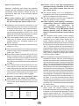
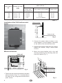
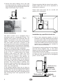
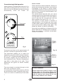
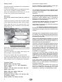
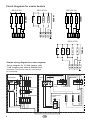
Installation and Operating Guide
38.AS
MADE IN GERMANY
GB
IP x4
1
Druck Nr. 29342172en / - 44.06
GB
Dear customer:
General instructions
Please note that optimum sauna climate conditions
can be achieved only if the cabin ventilation
(fresh air and exhaust) system, the sauna heater
and the control unit are designed and set to work
efficiently in combination.
You have purchased a high-quality sauna heater
that will give you years of sauna bathing pleasure.
This sauna heating unit has been designed in
conformity with the latest European safety
standards, tested and manufactured at our
production facility in accordance with quality
standard EN DIN ISO 9001.
Please observe the instructions and information
provided by your sauna supplier.
Sauna heating units heat your sauna cabin with
warmed convection air. Fresh air drawn by
suction pressure through the fresh-air inlet is
heated, rises upward (convection) and is then
circulated within the cabin. Some of the consumed
air is forced out of the cabin through the exhaust
outlet. This process produces a typical sauna
climate, with temperatures of approximately
110° C immediately below the ceiling and a
temperature gradient that produces low
temperatures of approximately 30-40° C at floor
level. Thus it is not unusual for the temperature
sensor above the heater to register 110° C,
while the thermometer mounted on the sauna
wall approximately 20-25 cm below the cabin
ceiling shows only 85° C. Ordinarily, sauna
temperatures range between 80° C and 90° C at
the level of the upper recliner bench at the
maximum temperature setting.
This detailed Installation and Operating Guide
has been prepared for your information. Please
give special attention to the Special Instructions
and information regarding electrical connections
and wiring.
We wish you many hours of pleasant, stimulating
sauna bathing.
Prior to installation, please check to ensure that
the sauna heating unit has been delivered to you
in proper condition. Damage incurred in transport
should be reported immediately to the shipping
agent or the supplier who arranged delivery to
you.
The delivery package includes the following
components:
1 sauna heater
Please remember that temperatures are always
at their highest just above the sauna heating unit
and ensure that temperature sensors and safety
limiters are mounted there.
1 accessory bag, including:
1 cable connector assembly PG 16
3 sheet metal screws B 4.2 x 9.5
When the unit is heated up for the first time,
evaporation of residual substances from the
production process may cause slight odors. The
cabin should be aired out thoroughly before you
begin your sauna bath.
4 tension-plate screws
1 set of sauna stones, packed separately in a
fabric bag
This device has not been designed for being
used by persons (including children) that are
physically or mentally handicapped or have
sensory disabilities. Moreover, it is not allowed
to use this device without sufficient experience
and/or knowledge, unless these persons will
be supervised by persons responsible for their
security or in case they have been instructed
how to use this device.
Children are to be supervised in order to make
sure that they do not play with this device.
2
GB
l Caution: Due to the high temperatures
generated during operation of the sauna
heating unit, direct contact with the unit
can cause burns.
Special Instructions
Improper installation can create fire hazards!
Please read the installation guide carefully and
completely. Strict attention should be paid to
dimensional data and to the following special
instructions.
l The sauna heating unit is not designed for
installation/use in a niche, beneath the reclining
bench or beneath an inclined ceiling.
l The sauna heating unit must not be operated
when the fresh-air inlet is closed.
lThe sauna heating unit is designed for
operation with an input voltage of 400 V
AC 3N through the sauna control unit.
l Cabin lighting and lighting installation
components must be splash-resistant
and
suitable
for
operation
at
environmental temperatures of up to
140°C. Therefore, only VDE-tested sauna
lighting systems (max. 40 Watt) may be
used in connection with the sauna heating
unit.2.
l Installation and electrical connection of the
sauna heating units, the control unit and other
electrical components must be performed by
a qualified electrician. The special safety
requirements specified in VDE 0110 v. § 49
DA/6 and VDE 0100, Part 703/2006-2 must be
observed during electrical installation.
l The complete sauna system (sauna heating
unit, control unit, lighting system, etc.) may be
connected to the main power system by a
locally certified electrician only. All electrical
wiring installed inside the cabin must be suitable
for use at environmental temperatures of up to
140° C. Silicone cables are recommended. If
single filament cables are used, they must be
protected with flexible metal tubing. Minimum
diameters for connection cables and suitable
cabin sizes for specific heating output values
in kW are listed in Table 2.
l The sauna heating and control units may be
used only in sauna cabins constructed of
suitable, resin-free, untreated material (e.g.
Nordic spruce).
l The sauna cabin must have a minimum inside
height of 1.90 m.
l Only one sauna heater providing the required
heating output may be installed in the sauna
cabin (see Table 2).
l Every sauna cabin must have a fresh-air inlet
and an exhaust outlet. All ventilation inlets/
outlets must be positioned behind the sauna
heating unit and approx. 5-10 cm above the
floor. Minimum inlet/outlet dimensions are listed
in Table 1.
l During installation of the sauna heating unit, it is
important to ensure that the vertical distance
between the upper surface of the sauna heating
unit and the sauna cabin ceiling is not less than
90 cm. The required horizontal (lateral) distance
between the sauna heating unit and the cabin
wall is shown in the dimensional diagram for the
each specific sauna heating unit. The distance
between the lower surface of the sauna heating
unit and the floor is also indicated in the dimensional diagram. This distance is equivalent to the
height of the base for floor-mounted heaters. In
all cases, it must be ensured that the sauna
heating unit is not placed on a floor comprised
of easily flammable material (wood, plastic floor
coverings, etc.). Ceramic tiles are recommended
for sauna floors.
l The exhaust outlet must be positioned in the
lower section of the rear wall of the sauna
cabin, diagonally opposite the sauna heating
unit. Fresh-air inlets and exhaust outlets must
not be closed. Please observe the instructions
provided by your sauna cabin supplier.
l Caution: Covered or improperly filled
stone grates can cause fire hazards.
l Please ensure that no objects have been left
lying on the sauna heating unit prior to each
operatio
Power input in kW
4,5
6,0
7,5
9,0
l The required distance between the heater
safety grate, the recliner bench or other
flammable materials to the sauna heating unit is
indicated in the dimensional diagram for each
specific sauna heating unit. The height of the
heater safety grate must be approximately
equal to the front height of the sauna heating
unit.
Minimum dimensions of fresh-air
inlets and exhaust outlets in cm
35
35
35
35
x
x
x
x
3
4
5
6
Table 1
3
GB
Power input in
kW
4,5
6,0
7,5
9,0
12,0
Minimum diameters in mm2 (copper lead) for connection to 380400 V AC 3N
Suitable for cabin
size
in m3
Power line from
power grid
to control unit
ca. 4 - 6
ca. 6 - 10
ca. 8 - 12
ca. 10 - 14
ca. 14 - 18
Heater connection cable
from control unit to heater
5 x 2,5
5 x 2,5
5 x 2,5
5 x 2,5
5x4
5 x 1,5
5 x 1,5
5 x 1,5
5 x 1,5
5 x 1,5 (2 Stück)
Fuses (in A)
3
3
3
3
3
x
x
x
x
x
16
16
16
16
25
Table 2
Installation of the 38 AS wall-mounted
heater
65 cm
59,5 cm
Wall mounting
bracket
Fresh-air inlet
Fig. 3
2. Connect the power cable as shown in the
circuit diagram. A circuit diagram is provided
on the inside of the terminal box cover.
3. Close the terminal box with the cover, spacer
toward the outside, using 2 sheet metal
screws.
Minimum distances
4. Mount the sauna heating unit to the wall
mounting bracket by the mounting slots and
insert the spacer (Fig. 7).
36,0 cm
Cabin wall
8 cm
65 cm
8 cm
Heater
safety grate
42 cm
mi
n.
10
8 cm
Fig. 2
cm
34
cm
Wall mounting
bracket
Fresh-air inlet
1. Fasten the wall mounting bracket to the cabin
wall as shown in Figs. 3 + 4, centered above
the fresh-air inlet, using the enclosed tension
plate screws.
4
Fig. 4
GB
5. Secure the sauna heating unit to the wall
mounting bracket by inserting a sheet metal
screw through the hole positioned at the rear
edge of the heater (Fig. 5 and 6).
Please remember that the sensor lines are thin,
flexible tubes that must not be squeezed or
subjected to pressure.
These lines must never be cut, as this will
destroy the components.
18 cm
20 cm
25 cm
Fig. 5
Securing
screw
Fig.6
Fiig. 7
Sensor installation
Installation by a qualified electrician
The built-in control unit is equipped with a
thermostat and an a temperature limiter. The
capillary tube sensors are delivered with the
heater unit (packed in the lower section of the
heater). The sensor must be removed carefully
from the heater and fixed in position in the
mounting holes on the sensor mounting bracket.
The capillary tubes must not be bent or damaged.
The smallest bending radius should not be less
than 4-5 cm during and after installation.
1.) Drill a hole measuring approx. 10 cm in
diameter in the cabin wall at the point where
the main power cable is to be inserted. Run
the cable through the hole toward the outside
of the sauna cabin and connect it to the main
power line in a distributor box suitable for
use in moist environments.
This operation must be performed in accordance
with the wiring diagram (Fig. 1), the circuit
diagram on the control panel and the regulations
of the local EVU and the VDE.
Caution! The local site installation must provide
for sufficient fuse capacity and an emergency
power cut-off switch.
The sensor mounting bracket is mounted (using
the provided wood screws) to the cabin wall as
shown in Fig. 7, centered above the heater
exhaust outlet facing the cabin door and
positioned 25 cm below the cabin ceiling, The
bracket must be placed in this position, as
otherwise the desired temperatures cannot be
achieved. The capillary tubes can be fastened
to the cabin wall with the fastening elements
provided. The excess length of capillary tube
should be rolled up behind the heater and must
not be pushed back into the connection box
under any circumstances.
Distributor box
suitable for
use in moist
environments
If the installed capillary tubes do not have an
insulating mantle, they must be protected against
contact. This can be accomplished by running
the tubes through the grooves in the wall paneling
and covering them with appropriate wood
molding.
5
Power cable
GB
Fresh-air
inlet Fig. 8
Commissioning/Initial operation
Sauna stones
Heater operation is initiated with the timer unit. You
may select a heating period of up to 4 hours. The
timer runs for the selected time period and then
automatically shuts the heater off.
Sauna stones are natural materials. Check your
sauna stones at regular intervals, since they are
susceptible to the effects of strong steamwater additives and may decompose over a long
period of time. Consult your sauna supplier if you
have any questions.
The sauna stones delivered with your sauna
heating system should be washed thoroughly in
running water and placed in the stone grate in
such a way that the convection-air can flow
freely between the stones (Fig. 10 + 11).
4
1
2
The quantity of sauna stones is sufficient to
vaporize approx. 10 cl of water per cubic meter
of cabin space. Wait for about 10 minutes after
each pouring before adding water again. This
allows the stones to heat up sufficiently.
Thermostat
Never add more additives or ethereal oils to the
steam water than is indicated on the containers.
Never use alcohol or undiluted concentrates.
Caution! Fire hazard.
3
1
4
5
Timer
3
2
Stone
grate
WARNUNG!
Bedeckung und nicht
gefüllter Steinkorb
verursacht Brandgefahr
Fig. 9
The sauna must heat up for approximately 45
minutes to achieve a typical sauna climate.
The thermostat enables you to select the
temperature you desire within a range of approx.
40° C to 110° C. Please remember, however, that
the sensors register only the temperatures in
their immediate vicinity. Therefore, temperatures
may differ in other parts of the cabin. These
differences are typical for sauna climates,
however.
Fig. 10
Sauna
stones
Fig. 11
The sauna heater is activated through a clock
timer with synchronous motor.
In consequence of the power frequency (50 Hz)
the synchronous motor is making some noise.
This is not a fault or insufficiency of the heater
!
6
URGENT WARNING!
Stones must not be piled in layers in the
stone grate on the sauna heater but
instead placed in a loose arrangement in
order to ensure that rising hot air can
flow freely between the stones.
GB
Instructions Leakage current
Safety cutoff
For the installation of sauna heaters, please pay
attention to the DIN VDE 0100 part 703 !
The sauna heater is equipped with a temperature
limiter for security.
In case of a malfunction this temperature limiter
cuts off all 3 phases by safety reasons.
Once the temperature limiter has cut off the
current, he must be reset mechanically.
This standard makes the following statement valid
in your newest expenditure, since February 2006,
paragraph 703.412.05;
Quotation:
The additional must be planned for all electric
circuits of the Sauna by one or more fault current
protection device (RCDs) with a calculation
difference stream not more largely than 30 mA,
excluded of it is Saunaheating.
Attention:
Cut off the sauna heater from the mains at
first.
Loosen the securtiy screw from the wall holder
of the heater and take the heater off the holder.
The EN 60335-1 DIN VDE 0700 part 1 of January 2001
states the following in paragraph 13; quote:
The leakage current may not exceed the following
values during operation:
Then open the lid of the terminal box. The
temperature limiter is mounted in the left lower
corner (fig.12).
for stationary heaters of protection class I
0,75 mA; or 0,75 mA each kW input of the appliance,
depending on the higher value, at a maximum value
of 5 mA.
3 locking pins behind
connecting plug
If the appliance is equipped with a protective device
for leakage current (ELCB), please pay attention to
the fact that no other electrical units will be
protected by this ELCB.
Under current manufacturing methods, it is not yet
possible to produce tubular heating elements for
sauna heaters which do not attract moisture on
each end from the surrounding air.
Abb. 12
Therefore, should the ELCB be triggered during
start-up, the electrical installation must be checked.
Temperature limiter for security
It is also possible that moisture from the
surrounding air has been concentrated in the
magnesium-oxide filling in the heating elements
during transport or storage and is now causing
the ELCB to be triggered.
Press the 3 locking pins of the connecting plug
back to the rear side of the housing until you feel
a switching point.
Close the terminal box again and restore the
sauna heater in the wall holder.
In this case, the oven must be heated up under
supervision of an expert, during which the PE
conductor is not connected. After about 10 minutes,
when moisture has evaporated from the heating
elements , the oven must be reconnected to the PE
conductor!
Secure the heater with the security screw.
In case the temperature limiter should cut off
again immediately after taking into operation, the
sauna heater has to be checked by a specialist.
If the sauna heater is not in use for a significant
period of time, we recommend running it every 6
weeks, so as to avoid moisture concentrating in
the heating elements.
Technical data
Voltage: 400 V AC 3N, 50 Hz
Power intake: 6.0, 7.5, kW, depending
upon model
Height: 730 mm when mounted 180 mm
above floor level
Width: 420 mm, depth: 360 mm
Stone capacity: 15 kg
Discharge current: max. 0.75 mA per kW
of heating output
Sauna heater for family saunas
7
Installation of the sauna heater and control unit
may be undertaken only by an authorized
electrician. Without documentation of such
installation, a warranty is fundamentally invalid.
GB
Circuit diagrams for sauna heaters
7500 W
2500 W
2500 W
6000 W
1500 W
1500 W
1500 W
1500 W
6000 W
U V W N
U V W N
2500 W
400 V AC 3N
400 V AC 3N
2000 W
2000 W
2000 W
400 V AC 3N
U V W N
Sample wiring diagram for a sauna system
Circuit diagram for 7.5 kW heaters (with
7 kW 3 heating coil units of 2000 W each)
Important! The ground lead (N) must always
be connected.
N L1 L2 L3
Sauna lamp
Fuses
U V W N
4-hr.
operating
timer
Thermostat
M
8
GB
2500 W
Coil radiator for
7,5 kW
Distributor box
2500 W
Main power
switch
2500 W
Temperature
limiter
7500 W
1500 W
1500 W
1500 W
1500 W
1500 W
400 V AC 3N
Care and maintenance
All sauna heating units are made of corrosion-resistant
material. However, to ensure that you get maximum
enjoyment from your sauna system for as long as
possible, the unit should be cleaned and maintained on
a regular basis. All openings and baffle plates must be
free of obstruction at all times. These areas are
susceptible to deposits of dust and fluff drawn into the
unit with fresh air. This impairs the air-convection
process in the sauna heating unit and can lead to
overheating.
Clean the equipment as needed. If defects or signs of
wear and tear are detected, consult your sauna supplier
or the manufacturer.
If you do not use your sauna for an extended period of
time, ensure before resuming sauna operation that no
cloths, cleaning agents or other objects have been left
on the sauna heating unit or the vaporizer.
Guarantee
The guarantee is taken over according to the legal
regulations at present.
Manufacturer’s warrenty
The period of warrenty starts from the date of
purchase and lasts up to 2years for commercial use and
3 years for private use.
Always include the completed warrenty
certificate when returning equipment.
The warrenty expires for appliances which have
been modified without manufacturer’s explicit agreement.
Damages caused by incorrect operation or
handling through non-authorized persons are not covered
under the terms of warranty.
In the event of a claim, please indicate the serial
number as well as the article code number and type name
with expressive description of the fault.
This warrenty covers damaged parts but no
defects due to wear and tear.
Use only original replacement parts, which can be
ordered from your supplier or directly from the
manufacturer.
In case of complaint please return the equipment in its
original packaging or other suitable packaging (caution:
danger of transport damage) to our service department.
Always include the completed warrenty certificate when
returning equipment.
Possible shipping costs arising from the transport to and
from point of repair cannot be borne by us.
Outside of Germany please contact your specialist
dealer in case of warranty claims. Direct warranty
processing with our service department is in this case not
possible.
Equipment start-up date:
Stamp and signature of the authorized electrician:
Service Adress:
EOS-Werke Günther GmbH
Adolf-Weiß-Str. 43
35759 Driedorf-Germany
tel: +49 (0) 27 75 82-240
fax: +49 (0) 27 75 82-455
[email protected]
www.eos-werke.de
9
GB