1
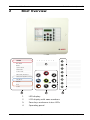
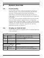
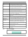
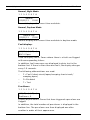
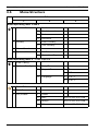
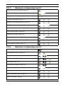
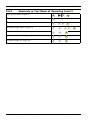
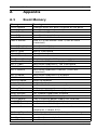
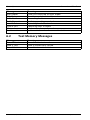
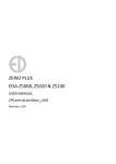
Conventional Fire Panel
FPC-500-2 | FPC-500-4 | FPC-500-8
en
Operation Guide
Conventional Fire Panel
Table of Contents | en
3
Table of Contents
1
Safety Instructions
4
2
Brief Overview
5
3
System Overview
6
3.1
Functionality
6
3.2
Display on Central Unit
6
3.3
The LCD Display
7
3.4
Operating Levels
9
3.5
Menu Structure
10
3.5.1
Shortcuts in Operating Level 1
11
3.5.2
Shortcuts in Operating Level 2
11
3.5.3
Shortcuts in Test Menu of Operating Level 2
12
4
Operation
13
4.1
Operating Level 1
13
4.1.1
Actions
13
4.1.2
Menu
15
4.2
Operating Level 2
18
4.2.1
Actions
19
4.2.2
Test/Disablements Menu
20
4.2.3
Menu
24
5
Troubleshooting
27
6
Maintenance
28
A
Appendix
29
A.1
Event Memory
29
A.2
Test Memory Messages
30
Index
31
Bosch Sicherheitssysteme GmbH
Operation Guide
F.01U.172.982 | 5.0 | 2012.04
4
1
en | Safety Instructions
Conventional Fire Panel
Safety Instructions
CAUTION!
Only silence alarms once you have ensured that no persons will
be endangered by the deactivation of the sirens.
CAUTION!
Only switch zones to test mode for brief periods of time. Zones
in test mode will not trigger an alarm in the event of a fire.
CAUTION!
Only deactivate zones for brief periods of time. Deactivated
zones will not trigger an alarm in the event of a fire.
NOTICE!
Your fire detection system and all connected components must
be subjected to professional maintenance on a regular basis.
Observe all local regulations.
DANGER!
The housing must only be opened by a specialist. There is a
danger of electric shock.
CAUTION!
Do not deactivate the power supply to the fire detection
system. After using up the emergency power supply, the fire
detection system will be unable to trigger a fire alarm.
NOTICE!
If you encounter any irregularities during the operation of your
fire detection system (fault messages etc.), contact your
specialist immediately.
F.01U.172.982 | 5.0 | 2012.04
Operation Guide
Bosch Sicherheitssysteme GmbH
Conventional Fire Panel
2
Brief Overview | en
5
Brief Overview
1
ALARM
2
3
4
Pre-Alarm
5
6
7
8
2
1
2
Fault
System Fault
3
Earth Fault
4
Power Fault
EVAC
NAC Fault / Disabled
5
Notification Appliance Silent
Day Mode
i
A CK
Disable
6
7
ESC
Test
RESET
Power
1
4
1
LED display
2
LCD display with zone numbers
3
Zone keys and zone status LEDs
4
Operating panel
Bosch Sicherheitssysteme GmbH
Operation Guide
8
3
F.01U.172.982 | 5.0 | 2012.04
6
en | System Overview
Conventional Fire Panel
3
System Overview
3.1
Functionality
The FPC-500 Fire Panel is the main component of your fire
detection system. As the central control unit, the FPC-500
manages all information received from the detectors.
Depending on the relevant programming, the FPC-500 Fire
Panel relays all alarms to the connected notification appliances
and outputs.
As the user, you can control the behavior of the entire system.
You can silence and reset triggered alarms, change alarm
triggering delays (day/night mode), test zones and much more.
However, the system can only be programmed by persons with
advanced user rights. Therefore, any faults etc. must be
reported to your on-site specialist.
3.2
Display on Central Unit
Your fire panel features a number of LEDs to indicate operating
states and faults.
Zone LED
Meaning
Red
Constant
The relevant zone is in alarm state.
Red
Flashing, 0.5 Hz
The zone has triggered a pre-alarm.
Yellow
Flashing, 0.5 Hz
The zone has a fault.
Yellow
Constant
The zone is deactivated.
Yellow
Flashing, 2 Hz
The zone is in test mode.
Notification appliance
Meaning
fault/disabled – LED
Yellow
Constant
Notification appliances are disabled.
Yellow
Flashing, 2 Hz
There is a fault in the notification appliance.
F.01U.172.982 | 5.0 | 2012.04
Operation Guide
Bosch Sicherheitssysteme GmbH
Conventional Fire Panel
System Overview | en
7
LED
Meaning
Fire
At least one zone has triggered a fire alarm. The LEDs
of the triggering zones are illuminated red.
Pre-Alarm
At least one zone has triggered a pre-alarm. The LED
flashes every 2 seconds. The LEDs of the zones that
have triggered the pre-alarm flash red.
Fault
At least one component in the system has a fault.
System fault
The system is or was not working correctly. Perform a
reset to check whether the fault persists.
Ground fault
The fire detection system continuously checks for an
earth connection (a panel wire is connected to the
ground). There is a ground fault.
Power supply fault
There is a fault in the power supply (battery or power
supply unit).
NAC fault/disabled
There is a fault on the notification appliance lines or
at least one notification appliance line is switched off.
Notification
The notification appliances have been silenced.
Appliance Silent
Day mode
The system is in daytime mode. Zones that are
programmed as alarm verification trigger an alarm.
You are prompted by the panel to verify the alarm.
Disablements
At least one system component is disabled. (Zone,
notification appliance, relay)
Test
At least one zone is in test mode. The relevant zone
LEDs flash at 2 Hz.
Power
Lit continuously in green when the system is supplied
with power.
3.3
The LCD Display
1
Bosch Sicherheitssysteme GmbH
2
3
4
Operation Guide
5
6
7
8
F.01U.172.982 | 5.0 | 2012.04
8
en | System Overview
Conventional Fire Panel
Normal, Night Mode
1 2 3 4 5 6 7 8
Normal
01/01/11
01:00
Normal display with current time and date.
Normal, Daytime Mode
1 2 3 4 5 6 7 8
Normal Day
01/01/11
01:00
Normal display with current time and date in daytime mode.
Fault displays
1 2 3 4 5 6 7 8
|F|D| | |T| |
NAC # Open
Used to display faults. Zones where there is a fault are flagged
with corresponding letters.
In addition, fault messages are displayed in plain text in the
bottom line. If there is more than one fault, the display changes
every 1.5 seconds.
The following abbreviations are used:
–
F = Fault (short-circuit/open/creeping short-circuit/
creeping open)
–
D =Disabled
–
T = Test
Pre-Alarms
1 2 3 4 5 6 7 8
|P|P| | |P| |
PreAlarms: 3
Display of pre-alarms. Zones that have triggered a pre-alarm are
flagged
In addition, the total number of pre-alarms is displayed in the
bottom line. The pre-alarms are then displayed one after
another in order of their appearance.
F.01U.172.982 | 5.0 | 2012.04
Operation Guide
Bosch Sicherheitssysteme GmbH
Conventional Fire Panel
System Overview | en
9
Alarms
1 2 3 4 5 6 7 8
|?| | | | | |
Fire Alarms: 1
Display of alarms. Zones that have triggered an alarm are
flagged.
In addition, the total number of alarms is displayed in the
bottom line, along with the sequence of the triggered alarms.
3.4
Operating Levels
This fire panel has three operating levels. You can only perform
certain actions on certain operating levels.
Level 1
Level 2
–
Display information
–
Read out event memory
–
Display faults and deactivations
–
Perform display test
–
Change language and time/date
–
Switch key tones on/off
–
Put zones in test mode and take zones out of test mode
–
Switch off/on zones, notification appliances, relays and
–
Trigger evacuations
transistor outputs
Level 3
–
Reset panel
–
Switch between day/night mode
–
All actions of level 1
–
All settings for installing and programming the system.
Code inputs are necessary for accessing operating levels 2 and
3.
Operating level 2 can be accessed using the optional key or an
input with the appropriate configuration.
Bosch Sicherheitssysteme GmbH
Operation Guide
F.01U.172.982 | 5.0 | 2012.04
10
en | System Overview
3.5
Conventional Fire Panel
Menu Structure
Submenu
1
2
3
Menu operating level 1 and 2
i
1
2
Current Events
History
1
Faults
-
-
2
Disablements
-
-
3
Test
-
-
4
PreAlarm
-
-
1
Event History
-
-
2
Test History
-
-
3
Alarm Counter
-
-
-
-
4
System Info
1
SW Release
-
-
2
Operation Days
-
-
Menu operating level 2 – code required
i
5
View Config
-
-
-
-
6
System Config
1
Date/Time
-
-
2
Keypad Tone
1
On
2
Off
1
1-A - L
2
2-M - Z
3
Language
Test menu
1
Test MMI
-
-
-
-
2
Test Zones
-
-
-
-
3
Dis/Enable
1
Zones
-
-
2
NAC
ACK #=YES ESC=No
3
Relays
ACK #=YES ESC=No
4
All
ACK #=YES ESC=No
F.01U.172.982 | 5.0 | 2012.04
Operation Guide
Bosch Sicherheitssysteme GmbH
Conventional Fire Panel
3.5.1
System Overview | en
11
Shortcuts in Operating Level 1
Deactivate internal buzzer (Page 14)
Perform display test (Page 14)
1
Display zone status (Page 14)
1
Check current faults (Page 15)
Display current disablements (Page 15)
Display current tests (Page 16)
Check current pre-alarms (Page 16)
Check event history (Page 16)
Display test history (Page 16)
Check alarm counter (Page 17)
Display software version (Page 17)
Check operating days (Page 17)
3.5.2
...
8
i
1
1
i
1
2
i
1
3
i
1
4
i
2
1
i
2
2
i
3
i
4
1
i
4
2
Shortcuts in Operating Level 2
Call up operating level 2 (Page 18)
+CODE
Exit operating level 2 (Page 18)
ACK
Switch between day/night mode (Page 19)
+CODE
Perform reset (Page 19)
RESET
ACK
+CODE
Evacuation (Page 19)
ACK
EVAC
+CODE
Silence alarm devices (Page 20)
+CODE
Display configuration (Page 25)
Set date/time (Page 25)
Switch key tones on/off (Page 25)
Select language (Page 26)
Bosch Sicherheitssysteme GmbH
Operation Guide
i
5
i
6
1
i
6
2
i
6
3
F.01U.172.982 | 5.0 | 2012.04
12
en | System Overview
3.5.3
Conventional Fire Panel
Shortcuts in Test Menu of Operating Level 2
Call up test menu (Page 21)
+CODE
Test MMI
1
Zones in test mode (Page 21)
2
Disable/enable zones (Page 22)
Disable/enable notification appliance
Disable/enable relay (Page 23)
Disable/enable all (Page 24)
F.01U.172.982 | 5.0 | 2012.04
Operation Guide
1
...
8
ACK
3
1
3
2
3
3
ACK
3
4
ACK
1
...
8
ACK
ACK
Bosch Sicherheitssysteme GmbH
Conventional Fire Panel
4
Operation | en
13
Operation
You have different options for navigating in the menu of the fire
panel.
Using autoscrolling
The menus scroll automatically every 2.5 seconds to the next
menu item. If you would like to select the menu item currently
ACK
shown, simply confirm with the ACK key.
Navigating with the zone keys
1
...
8
In the menu, each menu item has a number from 1 to 8
preceding it. Use the zone keys to select the desired menu
item in the menu. The desired menu item does not have to be
shown in the display.
Navigating with the arrow keys
Use the arrow keys to navigate in the menu.
i
Using the arrow keys stops autoscrolling in the menus.
Confirm your selection in the menu with the ACK key.
ACK
Exiting submenus
ESC
RESET
In the menu and in the submenus, you can jump to a higher
level or cancel the setting using the RESET (ESC) key.
Hold the RESET (ESC) key down for 2 seconds to jump to the
uppermost level.
4.1
Operating Level 1
4.1.1
Actions
The following actions can be performed in level 1:
Bosch Sicherheitssysteme GmbH
Operation Guide
F.01U.172.982 | 5.0 | 2012.04
14
en | Operation
Conventional Fire Panel
Alarm verification (if programmed)
NOTICE!
This procedure only applies to zones that are programmed as
alarm verification.
Note that the delay settings are only effective in day mode. In
night mode, the alarm is triggered immediately.
A zone programmed as alarm verification triggers an alarm,
which you must confirm manually.
Press the ACK button within the programmed confirmation
time.
ACK
The programmed verification time begins.
Check the area of the zone triggering the fire alarm to see if
there is really any fire.
If you have discovered a real fire, use either a manual call
point or the EVAC button to trigger the alarm.
In the event of a false alarm, you can reset the panel within
ESC
the programmed verification time using the RESET (ESC)
RESET
button.
NOTICE!
Once the confirmation time and verification time have elapsed
an alarm is triggered automatically.
Switching off the internal buzzer
Press the "Buzzer off" key.
The buzzer is now deactivated.
Perform display test
1
Press the "Test" key and then zone key 1.
All LEDs light up for three seconds and the buzzer sounds.
Checking the zone status
1
...
8
To check the status of a zone, press the relevant zone key
(1 to 8).
The LCD display shows the status of the selected zone.
F.01U.172.982 | 5.0 | 2012.04
Operation Guide
Bosch Sicherheitssysteme GmbH
Conventional Fire Panel
4.1.2
Operation | en
15
Menu
The following options are available in the menu:
–
1-Current Events
–
–
1-Faults
–
2-Disablements
–
3-Test
–
4-PreAlarm
2-History
–
1-Event History
–
2-Test History
–
3-Alarm Counter
–
4-System Info
–
1-SW Release
–
2-Operation Days
Opening the menu
Press the "Menu" key.
i
You are now in the menu.
Exiting the menu/submenus
Press the "Reset" key.
You have now moved up one level.
RESET
Displaying faults
Displays a list of all current faults with the corresponding time
stamps.
i
1
1
Press the "Menu" key and then zone key 1.
This takes you to the Current Events submenu.
Press zone key 1.
The LCD shows the current fault messages.
Displaying disablements
Displays a list of all current disablements with the
corresponding time stamps.
Bosch Sicherheitssysteme GmbH
Operation Guide
F.01U.172.982 | 5.0 | 2012.04
16
en | Operation
i
1
Conventional Fire Panel
Press the "Menu" key and then zone key 1.
This takes you to the Current Events submenu.
Press zone key 2.
2
The LCD display shows the current disablements.
Displaying zones in test mode
Shows a list of all current zones in test mode, including the
time stamp.
i
1
Press the "Menu" key and then zone key 1.
This takes you to the Current Events submenu.
Press zone key 3.
3
The LCD display shows the current tests.
Displaying pre-alarms
Displays a list of all current pre-alarms with the corresponding
time stamps.
i
1
Press the "Menu" key and then zone key 1.
This takes you to the Current Events submenu.
Press zone key 4.
4
The LCD display shows the current pre-alarms.
Displaying the event log
Displays a list of all events with the corresponding time stamps.
A list of events can be found in Section A.1 Event Memory,
page 29
i
1
2
Press the "Menu" key and then zone key 2.
This takes you to the History submenu.
Press zone key 1.
The messages in the event memory are displayed.
You can use the arrow keys to switch between the individual
entries. If you press and hold an arrow key, the display moves
10 steps in the corresponding direction. A description of the
displayed events can be found on Page 29 ff.
Displaying the test log
Call up the menu; see Section Opening the menu, page 15
F.01U.172.982 | 5.0 | 2012.04
Operation Guide
Bosch Sicherheitssysteme GmbH
Conventional Fire Panel
i
2
Operation | en
17
Press the "Menu" key and then zone key 2.
This takes you to the History submenu.
Press zone key 2.
2
The messages in the test memory are displayed.
You can use the arrow keys to switch between the individual
entries. If you press and hold an arrow key, the display moves
10 steps in the corresponding direction. A description of the
displayed events can be found on Page 30.
If the test log should be disabled, "No Entry" appears on the
LCD.
Displaying alarm counters
Call up the menu; see Section Opening the menu, page 15
i
3
Press the "Menu" key and then zone key 3.
The LCD shows the number of alarms since the initial start-up.
The alarm counter cannot be deleted. It only counts alarms
triggered by zones up to 999. It does not count pre-alarms or
evacuations triggered manually via the panel or the inputs.
Displaying SW Release
Call up the menu; see Page 15.
i
4
Press the "Menu" key and then zone key 4.
This takes you to the System Info submenu.
Press zone key 1.
1
The software version is displayed.
Displaying the operation days
Call up the menu; see Section Opening the menu, page 15
i
2
4
Press the "Menu" key and then zone key 4.
This takes you to the System Info submenu.
Press zone key 2.
The number of operation days is displayed
Bosch Sicherheitssysteme GmbH
Operation Guide
F.01U.172.982 | 5.0 | 2012.04
18
en | Operation
4.2
Conventional Fire Panel
Operating Level 2
To be able to perform the actions in operating level 2, you will
need a code you can enter with the zone keys.
Calling up operating level 2 via a code
Press the "Code input" key.
You will be prompted to enter a code.
Enter the code with zone keys 1 to 8. The preset code is 1234.
CODE
The code can be changed in operating level 3.
If you are in level 2, a small 2 is displayed in the top right corner
of the display.
Calling up operating level 2 via a key (optional)
Use the key to open operating level 2. Leave the key turned in
the lock while you are working in operating level 2.
Automatic exit of level 2
If you are in level 2 and a key has not been pressed for 10
minutes, the system will exit level 2 automatically. This also
applies if you are using a key.
One minute before exiting level 2, a pulse tone from the internal
buzzer indicates the passing time, while a countdown is shown
in the LCD display.
Exiting operating level 2
If you are in operating level 2, proceed as follows.
Press the "Code input" key.
–
ACK
Press the ACK key.
You exit operating level 2.
RESET
–
Press the "Reset" key.
You remain in operating level 2.
If you accessed operating level 2 using the optional key, turn
the key back and remove it from the lock to exit operating level
2.
F.01U.172.982 | 5.0 | 2012.04
Operation Guide
Bosch Sicherheitssysteme GmbH
Conventional Fire Panel
4.2.1
Operation | en
19
Actions
Switching between day and night mode
Press the "Day/night mode" key.
The "Day mode" LED is illuminated in day mode and
deactivated in night mode. The LCD shows Normal in night
mode and Normal Day in day mode.
In day mode, delay times are activated in zones that are
programmed as alarm verification.
Performing a reset
Press the "Reset" key.
RESET
–
ACK
Press the ACK key.
The fire panel performs a reset if it is not in a normal
RESET
state.
–
Press the "Reset" key.
No reset is performed.
Trigger evacuation, test alarm
NOTICE!
Only trigger an evacuation if you want to trigger a test alarm.
You can only trigger a test alarm when the fire panel is in the
normal state.
NOTICE!
As standard, the EVAC button only activates the notification
appliances.
CAUTION!
If you have discovered a real fire, use a manual call point to
trigger the alarm.
Bosch Sicherheitssysteme GmbH
Operation Guide
F.01U.172.982 | 5.0 | 2012.04
20
en | Operation
Conventional Fire Panel
Press the "Evacuation" key.
EVAC
–
ACK
Press the ACK key.
The fire panel activates all notification appliances and
RESET
relays as programmed.
–
Press the "Reset" key.
No evacuation is triggered.
EVAC button functions
The EVAC button has various functions, depending on the
status of the fire panel:
–
Panel in normal state
You can trigger a test alarm using the EVAC button.
–
Panel in alarm state
If you have silenced the notification appliances, you can
reactivate them using the EVAC button.
–
Panel in alarm verification, dual-zone dependency, or dualdetector dependency state
The delay for the alarm notification appliances is ended.
The notification appliances are triggered immediately.
Silencing notification appliances
NOTICE!
Only silence an alarm once you have made sure that there is not
actually a fire.
You can reactivate silenced alarm devices using the EVAC
button.
Press the "Silence notification appliance" key.
The fire panel deactivates all notification appliances and
relays as programmed. A new alarm reactivates the
notification appliances and relays, if programmed.
4.2.2
Test/Disablements Menu
The following options are available in the test menu:
–
1-Test MMI
–
2-Test Zones
F.01U.172.982 | 5.0 | 2012.04
Operation Guide
Bosch Sicherheitssysteme GmbH
Conventional Fire Panel
–
Operation | en
21
3-Dis/Enable
–
1-Zones
–
2-NAC
–
3-Relays
–
4-All
Calling up the test menu
Press the "Test" key.
You are now in the test menu.
Performing an MMI test
See Section Perform display test, page 14.
Switching zones to test mode
CAUTION!
Only switch zones to test mode for brief periods of time. Zones
in test mode will not trigger an alarm in the event of a fire.
2
1
...
8
Press the "Test" key and then zone key 2.
This takes you to the Test Zones submenu
Select the zones to be set to test mode. To do this, press the
relevant zone keys 1 to 8. A code appears below the selected
zone(s) in the LCD. Multiple zones can be switched to test
mode at the same time.
Confirm your selection with the ACK key.
ACK
The "Test" LED and the LEDs for the selected zones are
illuminated yellow.
NOTICE!
Only zones that are in a normal state can be set to test mode.
Selecting a zone again removes it from test mode.
Bosch Sicherheitssysteme GmbH
Operation Guide
F.01U.172.982 | 5.0 | 2012.04
22
en | Operation
Conventional Fire Panel
Testing the zones
NOTICE!
The fire panel features a test memory, which stores all the
panel's testing procedures. All memory entries are assigned a
date and time stamp and cannot be deleted.
The test memory can be called in operating levels 1 and 2.
Use a manufacturer-approved test device to test each individual
detector in the zones currently in test mode. In each case, use
the test device to trigger an alarm.
NOTICE!
The fire panel test function is designed for operation by a single
person:
The fire panel automatically resets the alarm 15 seconds after
an alarm is triggered in a zone in test mode. This is followed by
the set time for disabling the zone and the stabilization time for
the detectors. The next detector can then be tested.
Removing individual zones from test mode
Access the Zones menu in test mode as described above. Use
the zone keys to cancel test mode for the relevant zones. The
code below the selected zone in the LCD disappears.
Disabling zones
CAUTION!
Only disable zones for brief periods of time. Disabled zones will
not trigger an alarm in the event of a fire.
3
1
Press the "Test" key and then zone key 3.
This takes you to the Dis/Enable submenu
Press zone key 1.
This takes you to the Zones submenu
F.01U.172.982 | 5.0 | 2012.04
Operation Guide
Bosch Sicherheitssysteme GmbH
Conventional Fire Panel
1
...
Operation | en
23
Select the zones to be disabled. To do so, press the relevant
8
zone keys (1 to 8).
A code appears below the selected zone(s) in the LCD.
Confirm your selection with the ACK key.
The "Disable" LED and the LEDs for the selected zones are
ACK
illuminated yellow.
Re-enabling zones
Go to the Disable Zones menu as described above. Use the zone
keys to cancel existing disablements. The code below the
selected zone in the LCD disappears.
Disabling notification appliances
3
This takes you to the Dis/Enable submenu
Press zone key 2.
2
ACK
Press the "Test" key and then zone key 3.
You are prompted to confirm the disablement.
–
Press the ACK key.
–
Press the "Reset" key.
The notification appliances are now disabled.
RESET
The notification appliances are not disabled.
When you disable the notification appliances, a message
confirming the disablement appears on the LCD after exiting
the menu.
Re-enabling notification appliances
Go to the Disable NAC menu as described above. You are
prompted to confirm the re-enablement. Press the ACK key. The
notification appliances are re-enabled.
Disabling relays
3
Press the "Test" key and then zone key 3.
This takes you to the Dis/Enable submenu
Bosch Sicherheitssysteme GmbH
Operation Guide
F.01U.172.982 | 5.0 | 2012.04
24
en | Operation
Press zone key 3.
3
You are prompted to confirm the disablement.
–
ACK
Conventional Fire Panel
Press the ACK key.
The relays are now disabled.
RESET
–
Press the "Reset" key.
The relays are not disabled.
When you disable the relays, a message confirming the
disablement appears on the LCD after exiting the menu.
Re-enabling relays
Go to the Disable Relays menu as described above. You are
prompted to confirm the re-enablement. Press the ACK key. The
relays are re-enabled.
Disabling/enabling All (zones, relays, notification appliances)
3
4
Press the "Test" key and then zone key 3.
This takes you to the Dis/Enable submenu.
Press zone key 4.
This takes you to the All submenu.
Upon confirmation via the ACK key, all zones, relays and
ACK
notification appliances will be disabled/re-enabled.
You can use the "Enable All" function if only one relay, one zone
or one notification appliance has been disabled.
4.2.3
Menu
In addition to the functions in level 1, the menu provides the
following options:
–
5-View Config
–
6-System Config
–
1-Date/Time
–
2-Keypad Tone
–
3-Language
- 1- A–L
- 2- M–Z
F.01U.172.982 | 5.0 | 2012.04
Operation Guide
Bosch Sicherheitssysteme GmbH
Conventional Fire Panel
Operation | en
25
Displaying the configuration
i
5
Press the "Menu" key and then zone key 5.
This takes you to the View Config submenu.
The set configuration is automatically shown in the LCD
i
display. The individual settings are displayed successively at
2.5-second intervals. If you use the arrow keys to navigate
manually through the configuration display, the automatic
process is cancelled.
Press the "Reset" key.
You exit the configuration display.
RESET
Setting the date/time
i
6
Press the "Menu" key and then zone key 6.
This takes you to the System Config submenu.
Press zone key 1.
1
You can now set the date and time.
The current entry is displayed.
i
Use the arrow keys to change the flashing value.
To save the currently displayed value, press the ACK key.
ACK
Repeat the steps to set the month, year, hour and minute.
Setting the buzzer beep
i
6
This takes you to the System Config submenu.
Press zone key 2.
2
1
Press the "Menu" key and then zone key 6.
You can now set the buzzer beep.
...
2
Press the zone keys to set the buzzer beeps:
–
1=On (default setting)
–
2 Off
Bosch Sicherheitssysteme GmbH
Operation Guide
F.01U.172.982 | 5.0 | 2012.04
26
en | Operation
Conventional Fire Panel
Setting the language
i
6
This takes you to the Language submenu.
Press zone key 1 to select a language in the A - L range.
1
...
8
Use the zone keys to set the relevant language.
–
1 čeština
–
2 Deutsch
–
3 English
–
4 Español
–
5 Français
–
6 Italiano
Press zone key 2 to select a language in the M - Z range.
2
1
This takes you to the System Config submenu.
Press zone key 3.
3
1
Press the "Menu" key and then zone key 6.
...
8
Use the zone keys to set the relevant language.
–
1 Magyar
–
2 Nederlands
–
3 Polski
–
4 Português
–
5 Român
–
6 Turkçe
NOTICE!
If you have selected the incorrect language, you can select the
language again when restarting by using a cold start
(disconnect power from system).
F.01U.172.982 | 5.0 | 2012.04
Operation Guide
Bosch Sicherheitssysteme GmbH
Conventional Fire Panel
5
Troubleshooting | en
27
Troubleshooting
"Fault" LED lit
Check the fault message memory
Perform a system reset. If you cannot resolve the fault, please
contact your specialist.
"System fault" LED lit
The system is or was not working correctly. In the event of a
system fault, the system performs an automatic reset. The fault
display is retained for safety reasons.
Perform a reset. If this does not resolve the fault, please
contact your specialist immediately.
"Ground fault" LED lit
There is a fault in the cabling (one line in the panel is connected
to earth). Perform a system reset. If you cannot resolve the
fault, please contact your specialist immediately.
"Power supply fault" LED lit
There is a fault with the power supply (mains or battery).
Perform a system reset. If you cannot resolve the fault, please
contact your specialist immediately.
"Notification appliance fault/disabled" LED flashing
There is a fault with the notification appliances. Perform a
system reset. If you cannot resolve the fault, please contact
your specialist immediately.
Bosch Sicherheitssysteme GmbH
Operation Guide
F.01U.172.982 | 5.0 | 2012.04
28
6
en | Maintenance
Conventional Fire Panel
Maintenance
Keep a log book that includes the following data as a minimum:
–
Information on the monitored object
–
Contact details of the maintenance company
–
Events
Record all events, such as alarms, faults and services, in this log
book.
Ensure that an inspection is carried out on your fire detection
system four times a year at roughly regular intervals.
Ensure that the following function checks are carried out during
the inspection:
–
Trigger an automatic detector for each zone to check the
transmission lines and notification appliances
–
Test the condition of the batteries and the function of the
–
Check the log book
power supply unit
Record the inspection and the results in the log book.
Carry out the following additional checks at least once a year:
–
Check all elements of the fire panel
–
Trigger all detectors that can be tested without being
damaged
–
Visually check all cabling and elements
NOTICE!
–
Have maintenance and inspection work carried out
regularly by trained, qualified personnel
–
Please observe the appropriate requirements stipulated by
the local authorities (e.g. fire service)
NOTICE!
Replace the batteries regularly. Please observe the appropriate
requirements stipulated by the local authorities etc.
F.01U.172.982 | 5.0 | 2012.04
Operation Guide
Bosch Sicherheitssysteme GmbH
Conventional Fire Panel
| en
A
Appendix
A.1
Event Memory
Message
Drill/Evacuate
Zone # Alarm
Zone # PreAlarm
Zone # Open
Zone # Short
Zone # Normal
Meaning
A manual alarm has been triggered on the panel.
Zone # has triggered an alarm.
Zone # has triggered a pre-alarm.
Zone # is interrupted.
Zone # has a short-circuit.
Zone # is in the normal state. (Fault or alarm
Zone # Disabled
Zone # Enabled
Input # Open
Input # Short
Input # Normal
Aux Power Short
Aux Power Normal
NAC # Open
NAC # Short
NAC # Normal
eliminated)
Zone # is disabled.
Zone # was enabled.
Input # interrupted.
Input # short-circuit.
Input # normal.
Short-circuit in the AUX power supply
Fault in the AUX power supply rectified.
Notification appliance #, line interrupted
Notification appliance #, short-circuit on line.
Notification appliance # normal. (Fault was
NAC Enabled
NAC Disabled
Relays Enabled
Relays Disabled
Battery Fault
Battery Restore
Mains Fault
Mains Restore
Ext PS Fault
Ext PS Normal
Ext BATT Fault
Ext BATT Normal
Sys Load Fault
eliminated)
Notification appliances re-enabled.
Notification appliances disabled.
Relays re-enabled.
Relays disabled.
Fault in the battery power supply.
Battery power supply was restored.
Fault in the 230 V power supply.
230 V power supply was restored.
Fault in external power supply unit.
Fault in external power supply unit resolved.
Fault in external battery.
Fault in external battery resolved.
Current consumption of panel and all connected
Sys Load Normal
System Fault
Panel boot-up
Reset Panel
peripherals is above 3.5 A.
Current consumption is back in permitted range.
System fault
Panel has been restarted.
Panel has been reset.
Bosch Sicherheitssysteme GmbH
Operation Guide
29
F.01U.172.982 | 5.0 | 2012.04
30
en |
Conventional Fire Panel
Message
Night Mode
Day Mode
Earth Fault
Earth Normal
Level # Enter
Level # Exit
Silenced
Unsilenced
A.2
Meaning
Panel has switched to night mode.
Panel has switched to day mode.
Grounding fault.
Fault in grounding resolved.
Operating level # entered.
Operating level # exited.
An alarm has been silenced.
A silenced alarm has been reactivated.
Test Memory Messages
Message
Zone # Start
Zone # Test
Zone # End
F.01U.172.982 | 5.0 | 2012.04
Meaning
Zone # set to test mode.
Zone # successfully tested.
Zone # test mode exited.
Operation Guide
Bosch Sicherheitssysteme GmbH
Conventional Fire Panel
Index | en
31
Index
A
Alarm counter
Displaying 17
Alarm devices
Silencing 20
Alarm Verification 14
All
Disable 24
Event memory
Displaying 16
F
Fault displays
LCD display 8
Faults 15
Display 15
Functionality 6
B
L
Buzzer
Switching off 14
Buzzer beep
Setting 25
Language
Setting 26
LED 7
Day mode 7
Disablements 7
Fault 7
Fire 7
Ground fault 7
NAC fault 7
Notification appliance silent 7
Power 7
Power supply fault 7
Pre-Alarm 7
System fault 7
Test 7
Zone 6
C
Calling up
Test menu 21
Configuration
Displaying 25
D
Date/time
Setting 25
Day/night mode
Switching 19
Disable
All 24
Notification appliances 23
Relays 23
Zones 22
Disablements
Display 15
Display 15
Disablements 15
Test log 16
Display test 14
Displaying
Alarm counter 17
Event memory 16
Operation days 17
Pre-alarms 16
Software version 17
E
M
Manual alarm verification 14
Menu
Exiting 15
Opening 15
N
Navigating
Arrow keys 13
Navigation
Zone keys 13
Notification appliances
Disable 23
O
Opening
Menu 15
Evacuation 20
Bosch Sicherheitssysteme GmbH
Operation Guide
F.01U.172.982 | 5.0 | 2012.04
32
en | Index
Conventional Fire Panel
Operating level 2
Exiting 18
Exiting automatically 18
Opening, with code 18
Opening, with key 18
Operation days
Displaying 17
P
Performing
Reset 19
Pre-alarms
Displaying 16
R
Relays
Disable 23
Reset
Performing 19
S
Setting
Buzzer beep 25
Date/time 25
Language 26
Software version
Displaying 17
Submenu
Exiting 15
Switching
Day/night mode 19
Switching off
Buzzer 14
T
Test log
Display 16
Test menu 20
Calling up 21
Test mode
Zones 21
Tests
Displaying 16
Z
Zones
Checking 14
Disable 22
Test mode 21
F.01U.172.982 | 5.0 | 2012.04
Operation Guide
Bosch Sicherheitssysteme GmbH
Bosch Sicherheitssysteme GmbH
Robert-Bosch-Ring 5
85630 Grasbrunn
Germany
www.boschsecurity.com
© Bosch Sicherheitssysteme GmbH, 2012